EP3014335B1 - Anzeige mit einem optischen wellenleiter zum anzeigen eines bilds - Google Patents
Anzeige mit einem optischen wellenleiter zum anzeigen eines bilds Download PDFInfo
- Publication number
- EP3014335B1 EP3014335B1 EP14735645.5A EP14735645A EP3014335B1 EP 3014335 B1 EP3014335 B1 EP 3014335B1 EP 14735645 A EP14735645 A EP 14735645A EP 3014335 B1 EP3014335 B1 EP 3014335B1
- Authority
- EP
- European Patent Office
- Prior art keywords
- image
- light
- optical waveguide
- output
- bearing light
- Prior art date
- Legal status (The legal status is an assumption and is not a legal conclusion. Google has not performed a legal analysis and makes no representation as to the accuracy of the status listed.)
- Active
Links
Images


Classifications
-
- G—PHYSICS
- G02—OPTICS
- G02B—OPTICAL ELEMENTS, SYSTEMS OR APPARATUS
- G02B27/00—Optical systems or apparatus not provided for by any of the groups G02B1/00 - G02B26/00, G02B30/00
- G02B27/01—Head-up displays
- G02B27/0101—Head-up displays characterised by optical features
-
- G—PHYSICS
- G02—OPTICS
- G02B—OPTICAL ELEMENTS, SYSTEMS OR APPARATUS
- G02B27/00—Optical systems or apparatus not provided for by any of the groups G02B1/00 - G02B26/00, G02B30/00
- G02B27/0081—Optical systems or apparatus not provided for by any of the groups G02B1/00 - G02B26/00, G02B30/00 with means for altering, e.g. enlarging, the entrance or exit pupil
-
- G—PHYSICS
- G02—OPTICS
- G02B—OPTICAL ELEMENTS, SYSTEMS OR APPARATUS
- G02B27/00—Optical systems or apparatus not provided for by any of the groups G02B1/00 - G02B26/00, G02B30/00
- G02B27/10—Beam splitting or combining systems
- G02B27/14—Beam splitting or combining systems operating by reflection only
- G02B27/141—Beam splitting or combining systems operating by reflection only using dichroic mirrors
-
- G—PHYSICS
- G02—OPTICS
- G02B—OPTICAL ELEMENTS, SYSTEMS OR APPARATUS
- G02B6/00—Light guides; Structural details of arrangements comprising light guides and other optical elements, e.g. couplings
-
- G—PHYSICS
- G02—OPTICS
- G02B—OPTICAL ELEMENTS, SYSTEMS OR APPARATUS
- G02B6/00—Light guides; Structural details of arrangements comprising light guides and other optical elements, e.g. couplings
- G02B6/0001—Light guides; Structural details of arrangements comprising light guides and other optical elements, e.g. couplings specially adapted for lighting devices or systems
- G02B6/0011—Light guides; Structural details of arrangements comprising light guides and other optical elements, e.g. couplings specially adapted for lighting devices or systems the light guides being planar or of plate-like form
- G02B6/0013—Means for improving the coupling-in of light from the light source into the light guide
- G02B6/0023—Means for improving the coupling-in of light from the light source into the light guide provided by one optical element, or plurality thereof, placed between the light guide and the light source, or around the light source
- G02B6/0026—Wavelength selective element, sheet or layer, e.g. filter or grating
-
- G—PHYSICS
- G02—OPTICS
- G02B—OPTICAL ELEMENTS, SYSTEMS OR APPARATUS
- G02B6/00—Light guides; Structural details of arrangements comprising light guides and other optical elements, e.g. couplings
- G02B6/0001—Light guides; Structural details of arrangements comprising light guides and other optical elements, e.g. couplings specially adapted for lighting devices or systems
- G02B6/0011—Light guides; Structural details of arrangements comprising light guides and other optical elements, e.g. couplings specially adapted for lighting devices or systems the light guides being planar or of plate-like form
- G02B6/0033—Means for improving the coupling-out of light from the light guide
- G02B6/0035—Means for improving the coupling-out of light from the light guide provided on the surface of the light guide or in the bulk of it
- G02B6/0045—Means for improving the coupling-out of light from the light guide provided on the surface of the light guide or in the bulk of it by shaping at least a portion of the light guide
- G02B6/0046—Tapered light guide, e.g. wedge-shaped light guide
-
- G—PHYSICS
- G02—OPTICS
- G02B—OPTICAL ELEMENTS, SYSTEMS OR APPARATUS
- G02B6/00—Light guides; Structural details of arrangements comprising light guides and other optical elements, e.g. couplings
- G02B6/0001—Light guides; Structural details of arrangements comprising light guides and other optical elements, e.g. couplings specially adapted for lighting devices or systems
- G02B6/0011—Light guides; Structural details of arrangements comprising light guides and other optical elements, e.g. couplings specially adapted for lighting devices or systems the light guides being planar or of plate-like form
- G02B6/0033—Means for improving the coupling-out of light from the light guide
- G02B6/005—Means for improving the coupling-out of light from the light guide provided by one optical element, or plurality thereof, placed on the light output side of the light guide
-
- G—PHYSICS
- G02—OPTICS
- G02B—OPTICAL ELEMENTS, SYSTEMS OR APPARATUS
- G02B6/00—Light guides; Structural details of arrangements comprising light guides and other optical elements, e.g. couplings
- G02B6/0001—Light guides; Structural details of arrangements comprising light guides and other optical elements, e.g. couplings specially adapted for lighting devices or systems
- G02B6/0011—Light guides; Structural details of arrangements comprising light guides and other optical elements, e.g. couplings specially adapted for lighting devices or systems the light guides being planar or of plate-like form
- G02B6/0033—Means for improving the coupling-out of light from the light guide
- G02B6/005—Means for improving the coupling-out of light from the light guide provided by one optical element, or plurality thereof, placed on the light output side of the light guide
- G02B6/0055—Reflecting element, sheet or layer
-
- G—PHYSICS
- G02—OPTICS
- G02B—OPTICAL ELEMENTS, SYSTEMS OR APPARATUS
- G02B27/00—Optical systems or apparatus not provided for by any of the groups G02B1/00 - G02B26/00, G02B30/00
- G02B27/01—Head-up displays
- G02B27/0101—Head-up displays characterised by optical features
- G02B2027/0123—Head-up displays characterised by optical features comprising devices increasing the field of view
-
- G—PHYSICS
- G02—OPTICS
- G02B—OPTICAL ELEMENTS, SYSTEMS OR APPARATUS
- G02B27/00—Optical systems or apparatus not provided for by any of the groups G02B1/00 - G02B26/00, G02B30/00
- G02B27/01—Head-up displays
- G02B27/0149—Head-up displays characterised by mechanical features
- G02B2027/015—Head-up displays characterised by mechanical features involving arrangement aiming to get less bulky devices
-
- G—PHYSICS
- G02—OPTICS
- G02B—OPTICAL ELEMENTS, SYSTEMS OR APPARATUS
- G02B27/00—Optical systems or apparatus not provided for by any of the groups G02B1/00 - G02B26/00, G02B30/00
- G02B27/01—Head-up displays
- G02B2027/0192—Supplementary details
- G02B2027/0194—Supplementary details with combiner of laminated type, for optical or mechanical aspects
-
- G—PHYSICS
- G02—OPTICS
- G02B—OPTICAL ELEMENTS, SYSTEMS OR APPARATUS
- G02B6/00—Light guides; Structural details of arrangements comprising light guides and other optical elements, e.g. couplings
- G02B6/24—Coupling light guides
- G02B6/26—Optical coupling means
- G02B6/34—Optical coupling means utilising prism or grating
Definitions
- the invention relates to displays and methods for displaying an image for viewing by a user.
- the invention is suitable for projection displays such as for use in a head-up display or otherwise.
- US2005140644 relates to an image display unit.
- US2006039046A1 relates to an image combiner and image display.
- US2010111472A1 relates to a substrate guided relay with pupil expanding input coupler.
- JPH08113059A relates to a head-up display device for vehicle.
- US2012069413A1 relates to a near-eye display with on-axis symmetry.
- US2008239422A1 relates to a joined optical member, image display apparatus, and head-mounted display
- WO2012143701 A1 relates to a projection display.
- WO2010119240A1 relates to an optical waveguide and display device.
- Waveguide displays are particularly useful in providing a means for displaying an image in a region of limited space.
- image-bearing light is injected into a waveguide and is subsequently released from the waveguide for viewing, for example a helmet-mounted or head-up display device.
- image-bearing light may be focussed at infinity, and a viewer views/receives the released light directly.
- the viewer focusses on an image seen by looking at/through the transparent waveguide output area and this permits light from an ambient, external and real-world scene to also enter the viewers eye through the waveguide output area (without being guided).
- a desired image may be seen to overlay the external scene.
- Optical waveguides for display devices of this type often initially insert image-bearing light into the waveguide by a process of diffraction, such that inserted light propagates along the waveguide by total internal reflection towards an output part arranged to release guided light from the waveguide by a further process of diffraction, for viewing.
- a slab optical waveguide 1 is orientated vertically and receives image-bearing light 2 at an uppermost input region 3 of the waveguide, generally above the viewer 4, for guiding to a lower output region 5 generally in front of the viewer, in a direction towards a viewer.
- Light 6 from an external scene is able to pass through the output part of the waveguide towards the viewer such that the image-bearing light overlays the external scene as seen by the viewer.
- the waveguide must be generally vertical to permit output light to be viewed in the horizontal - a desired orientation in head-up displays. This can be problematic where there is limited vertical space/height available in a vehicle/aircraft, or on a helmet, for accommodating the waveguide.
- FIG. 2 An alternative arrangement is shown in Figure 2 in which the waveguide 1 is orientated in the horizontal plane above the viewer, who no longer views the output part of the waveguide directly.
- a combiner 7 is located in front of the viewer and comprises a flat sheet of material (e.g. a glass) generally reflective to the image-bearing light while being generally transmissive to external light 7 from an external scene. The combiner is thereby able to combine image-bearing light (reflected) and light from an external scene (transmitted) for concurrent viewing by the viewer.
- a flat sheet of material e.g. a glass
- the invention aims to provide an improved waveguide display.
- the invention is to position a waveguide display unit between a combiner unit and the intended viewing position of a user, and to direct the output of the waveguide display unit towards the combiner unit for back-reflection to the viewer through the waveguide display unit.
- the invention may provide a display apparatus for use in displaying an image to a viewer, comprising an optical waveguide arranged to receive image-bearing light into the optical waveguide to guide the received image-bearing light therealong to an output part of the optical waveguide for output therefrom, the optical waveguide comprising an input diffraction grating for receiving image-bearing light and directing the received image-bearing light into the optical waveguide by diffraction, for guiding therealong and the output part comprises an output diffraction grating to output the image-bearing light wherein the input diffraction grating and output diffraction grating periods are matched, and a combiner arranged adjacent to the output part of the optical waveguide for reflecting image-bearing light output by the waveguide in a direction which passes back through the optical waveguide and for allowing light from an external scene to pass through the combiner in said direction through the optical waveguide to combine with the reflected image-bearing light so that the image-
- the optical waveguide is substantially planar and the combiner is substantially planar, and the optical waveguide and the combiner may be mutually orientated to converge towards each other at or adjacent the output part of the optical waveguide.
- the optical waveguide is substantially transparent to light conveying the image-bearing light and the external scene.
- the combiner may be substantially transparent to light conveying the external scene and more reflective than transmissive to light conveying the image-bearing light.
- the combiner may include a reflective coating which is predominantly reflective to image-bearing light (e.g. at optical wavelengths conveying that light) and predominantly transmissive to light conveying the external scene (e.g. at optical wavelengths conveying that).
- the combiner may include an anti-reflective coating which is predominantly transmissive at optical wavelengths conveying the external scene, thereby to increase the efficiency of transmission of light conveying the external scene therethrough.
- the waveguide includes an input diffraction grating for receiving image-bearing light and directing the received image-bearing light into the optical waveguide by diffraction, for guiding therealong.
- the waveguide may include an intermediate diffraction grating between the input diffraction grating and the output part for receiving image-bearing light from the input diffraction grating and expanding the image-bearing light in a first dimension generally transverse to the direction of guidance of light towards the output part.
- the output part includes an output diffraction grating for expanding the image-bearing light in a second dimension generally transverse to the first dimension, and to output the result by diffraction.
- the display apparatus may include an image source arranged for providing an image-bearing light output, for input to the optical waveguide.
- the optical waveguide may be a plate-like waveguide arranged to guide light therealong by total internal reflection between opposing substantially parallel sides of the waveguide.
- the optical waveguide is a rod-like waveguide arranged to guide light therealong by total internal reflection between opposing substantially parallel sides of the waveguide.
- the invention may provide a projection display apparatus comprising the display apparatus described above for projecting the image-bearing light and light from a said external scene concurrently to a viewer so that the image-bearing light overlays light from the external scene for viewing by the viewer.
- the invention may provide an aircraft or vehicle including a transparent canopy or windscreen and a display apparatus or projection display apparatus as described above wherein the combiner is located and arranged to allow an occupant to view though the combiner and through the optical waveguide the external scene being a scene external to the aircraft or vehicle, so that the image-bearing light overlays light from the external scene.
- the invention may provide a method for displaying an image to a viewer, comprising providing an optical waveguide and receiving image-bearing light into the optical waveguide to guide the received image-bearing light therealong to an output part of the optical waveguide, the optical waveguide comprising an input diffraction grating for receiving image-bearing light and directing the received image-bearing light into the optical waveguide by diffraction, for guiding therealong and the output part comprises an output diffraction grating to output the image-bearing light wherein the input diffraction grating and output diffraction grating periods are matched, and outputting the received image-bearing light therefrom, and providing a combiner arranged adjacent to the output part of the optical waveguide and reflecting image-bearing light output by the waveguide in a direction which passes back through the optical waveguide and allowing light from an external scene to pass through the combiner in said direction through the optical waveguide to combine with the reflected image-bearing light
- the display apparatus, or projection display apparatus may form a part of a Head-Up Display (HUD).
- HUD Head-Up Display
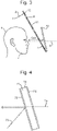
- Figure 3 shows a schematic view of a display apparatus according to an embodiment of the present invention.
- a planar slab waveguide display unit 8 is positioned within a cock-pit of an aircraft (or cabin of a vehicle) between a combiner unit 70 and the intended viewing position of a viewer 4 (e.g. pilot or driver).
- the waveguide unit is arranged such is shown in detail in Figure 5 , which shows a schematic view of the optical waveguide according to an embodiment of the invention.
- the planar (e.g. slab) waveguide 8 provides flat opposite surfaces (9, 10) for guiding light rays 11 along the waveguide between the opposing surfaces by successive total internal reflection (TIR) at alternate surfaces internally.
- An input light ray 2 is directed into the waveguide at a low angle of incidence which is insufficiently oblique to either of the opposing surfaces of the waveguide to permit TIR there.
- An input diffraction grating 12 is positioned upon a surface of the waveguide to receive the input light 2 and to diffract the received light in a direction forming an angle of incidence to the opposing surfaces (9, 10) of the waveguide internally which permits TIR.
- Guiding of the light ray 2 ensues until the guided light is incident upon an output diffraction grating 5 arranged upon the same surface 9 of the waveguide bearing the input grating 12.
- the output grating diffracts received light in a direction forming an angle of incidence to the opposite surface 10 of the waveguide internally which does not permit TIR, and the light ray is output from the waveguide for viewing.
- Image-bearing light may be focussed at infinity.
- the waveguide includes an intermediate diffraction grating 13 between the input diffraction grating and the output part for receiving image-bearing light from the input diffraction grating and expanding the image-bearing light in a first dimension generally transverse to the direction of guidance of light towards the output grating.
- the output diffraction grating is arranged to then expand the image-bearing light from the intermediate grating in a second dimension generally transverse to the first dimension (e.g. in the direction of guidance of light), and to output the result by diffraction.
- a small input pupil of image-bearing light may be expanded in two mutually perpendicular directions to produce an expanded exit pupil of image-bearing light for viewing.
- An example of a suitable such planar waveguide is described in international patent application number PCT/GB2010/000734 , published as WO2010/119240A1 on 21 October 2010 , entitled "Optical Waveguide and Display Device".
- the display apparatus includes an image source (not shown) arranged for providing an image-bearing light output, preferably collimated, for input to the optical waveguide.
- Image sources suitable for this purpose are readily available to the skilled person and will not be described here.
- the orientation of the grooves of the intermediate grating are inclined at an angle of e.g. 60° to the short/width axis (the "x-dimension") of the waveguide.
- Image-bearing light incident on the input diffraction grating is diffracted and directed such that the chief ray of the image-bearing light propagates and is incident on the grooves of the intermediate diffraction region at e.g. 30° to the normal to the grooves.
- the image-bearing light is partially diffracted and expanded in a first dimension, herein the x-dimension, and turned to propagate through the waveguide to a low efficiency (2% to 20%) output diffraction grating 5 having grating lines/grooves lying in the x-direction.
- the diffracted rays of image-bearing light are incident substantially normally on this grating and are partially diffracted out of the waveguide, the partial diffraction serves to expand the input pupil in a second dimension, here the long axis (the "y-dimension").
- a diffractive grating or surface can exhibit large amounts of dispersion of incident image bearing light.
- the correct matching of the diffractive gratings of the waveguide has the effect of mitigating chromatic aberration.
- the net chromatic aberration caused by the three diffraction regions shown in Figure 5 may preferably be zero or substantially zero.
- the input grating 12 and intermediate grating 13 may be matched with the output grating 5 to provide a net chromatic dispersion of substantially zero.
- This result is advantageous for a head-up display or a display used in head mounted or helmet mounted applications that incorporate such a waveguide assembly as it allows the use of a small, cheap and broadband image generating light source in place of a relatively costly, bulky and high powered monochromatic light source, for example a laser, to illuminate the waveguide assembly. Such a result also allows the display apparatus to correctly present multiple colour or full colour display images or information to a viewer.
- d i and d o are the periods of the input and output gratings respectively.
- the grating periods may be matched to avoid chromatic aberration for light sources other than monochromatic sources such as a laser. It will be appreciated that if it is required to match the gratings in this way to avoid chromatic aberration, light should be output from the waveguide generally perpendicularly and this being the case, it is not possible to match the gratings and also output the light at an angle other than generally 90 degrees.
- the additional combiner and the waveguide can be mutually orientated to occupy space efficiently even when subject to the restriction of a 90 degree output angle from the waveguide, and therefore the invention provides a noticeable advantage.
- FIG. 4 shows a cross-section view of the combiner 70.
- the combiner comprises an optically transparent planar substrate 71 typically made from glass.
- An optically reflective coating 72 is provided on one surface of the substrate.
- the coating may be a multi-layer dielectric coating having thicknesses and dielectric properties selected to be reflective to wavelengths present in the image-bearing light 73 (e.g. monochromatic, or multi-spectral) output from the waveguide but transmissive to wavelengths in light 74 from the external world scene.
- An anti-reflective layer 75 is provided on an opposing surface of the substrate configured to increase the transmission efficiency of light through the combiner.
- the anti-reflective layer may for example have a thickness of a quarter wavelength designed to produce interference to allow greater transmission.
- the wavelength selective coating 72 on the combiner improves efficiency by increasing the reflectance of the wavelengths used by the display device whilst also allowing transmission of the external scene.
- the waveguide unit is arranged to output the image-bearing light from the output grating in a direction generally away from the viewer, and towards the combiner unit for reflection from the planar surface of the combiner unit which is generally facing the output grating, and the viewer.
- the combiner unit is positioned and orientated to direct the output of the waveguide display unit towards the combiner unit for back-reflection to the viewer through the waveguide display unit. This permits a compact arrangement of the waveguide display unit and combiner unit which is generally desirable in space-limited environments such as within vehicles or aircraft (e.g. a cockpit).
- the reflected image-bearing light then passes back to the waveguide unit and reaches the output grating thereof.
- external light from an ambient, external and real-world scene is able to pass through the combiner unit in a direction towards the waveguide unit and, thence, the viewer. Consequently, image-bearing light and external-scene light are combined by the combiner and continue together towards the waveguide unit and the viewer.
- the majority of the combined light (reflected light and external-scene light) transmits through the waveguide unit without undergoing diffraction by the output grating. As a result, the majority of the combined light passes through the waveguide unit and on to the viewer for viewing substantially un-deviated.
- the viewer ultimately views/receives the released light indirectly via reflection from the combiner unit, and may focus on an image seen by looking at/through the transparent waveguide output area which permits light from the ambient, external and real-world scene to also enter the viewer's eye through the waveguide output area (without being guided). In this way, a desired image may be seen to overlay the external scene.
Landscapes
- Physics & Mathematics (AREA)
- General Physics & Mathematics (AREA)
- Optics & Photonics (AREA)
- Devices For Indicating Variable Information By Combining Individual Elements (AREA)
- Diffracting Gratings Or Hologram Optical Elements (AREA)
Claims (13)
- Anzeigevorrichtung zur Verwendung bei einem Anzeigen eines Bildes für einen Betrachter, die Folgendes umfasst:einen optischen Wellenleiter (8), der angeordnet ist, um bildtragendes Licht in den optischen Wellenleiter aufzunehmen, um das aufgenommene bildtragende Licht daran entlang zu einem Ausgangsteil des optischen Wellenleiters für eine Ausgabe davon zu leiten, wobei der optische Wellenleiter ein Eingangsbeugungsgitter (12) zum Aufnehmen von bildtragendem Licht und Richten des aufgenommenen bildtragenden Lichts in den optischen Wellenleiter durch Beugung zum Leiten daran entlang, und der Ausgangsteil ein Ausgangsbeugungsgitter (5) umfasst, um das bildtragende Licht auszugeben, wobei die Perioden des Eingangsbeugungsgitters und des Ausgangsbeugungsgitters übereinstimmen; und,ein Vereinigungselement (70), das angrenzend an den Ausgangsteil des optischen Wellenleiters angeordnet ist, zum Reflektieren des bildtragenden Lichts, das durch den Wellenleiter ausgegeben wird, in einer Richtung die durch den optischen Wellenleiter zurückführt, und zum Ermöglichen, dass Licht von einer externen Szene durch das Vereinigungselement in der Richtung durch den optischen Wellenleiter hindurch geführt wird, um sich mit dem reflektierten bildtragenden Licht zu vereinigen, so dass das bildtragende Licht Licht von der externen Szene zum Betrachten durch einen Betrachter überlagert,wobei der Ausgangsteil des optischen Wellenleiters im Wesentlichen eben ist und das Ausgangsbeugungsgitter angeordnet ist, um das bildtragende Licht in einer Ausgangsrichtung auszugeben, die im Wesentlichen senkrecht zu der Ebene davon ist, und das Vereinigungselement eine im Allgemeinen ebene Oberfläche aufweist, die relativ zu der Ebene des Ausgangsteils zum schrägen Reflektieren von bildtragendem Licht schräg orientiert ist.
- Anzeigevorrichtung nach einem der vorhergehenden Ansprüche, wobei der optische Wellenleiter (8) im Wesentlichen eben ist und das Vereinigungselement im Wesentlichen eben ist und der optische Wellenleiter (8) und das Vereinigungselement (70) gegenseitig orientiert sind, um zueinander an dem oder angrenzend an das Ausgangsteil des optischen Wellenleiters (8) zu konvergieren.
- Anzeigevorrichtung nach einem der vorhergehenden Ansprüche, wobei der optische Wellenleiter (8) für Licht bei optischen Wellenlängen, die das bildtragende Licht und die externe Szene transportieren, im Wesentlichen transparent ist, und das Vereinigungselement (70) für Licht bei optischen Wellenlängen, die die externe Szene transportieren, im Wesentlichen transparent ist und bei optischen Wellenlängen, die das bildgebende Licht transportieren, mehr reflektierend als durchlässig ist.
- Anzeigevorrichtung nach Anspruch 4, in der das Vereinigungselement (70) eine reflektierende Beschichtung beinhaltet, die bei optischen Wellenlängen, die das bildtragende Licht transportieren, überwiegend reflektierend und bei optischen Wellenlängen, die die externe Szene transportieren, überwiegend durchlässig ist, wobei dadurch die Reflexion von bildtragendem Licht daraus und das Übertragen von Licht, das die externe Szene dahindurch transportiert, erhöht wird.
- Anzeigevorrichtung nach Anspruch 4 oder 5, in der das Vereinigungselement (70) eine antireflektierende Beschichtung beinhaltet, die bei optischen Wellenlängen, die die externe Szene transportieren, überwiegend durchlässig ist, wobei dadurch die Effizienz der Übertragung des Lichts, das die externe Szene dahindurch transportiert, erhöht wird.
- Anzeigevorrichtung nach einem der vorhergehenden Ansprüche, in der der Wellenleiter (8) ein Zwischenbeugungsgitter (13) zwischen dem Eingangsbeugungsgitter (12) und dem Ausgangsteil zum Aufnehmen von bildtragendem Licht von dem Eingangsbeugungsgitter (12) und ein Erweitern des bildtragenden Lichts in einer ersten Dimension, im Allgemeinen quer zu der Richtung des Lichtleitens zu dem Ausgangsteil, beinhaltet.
- Anzeigevorrichtung nach Anspruch 6, wobei das Ausgangsbeugungsgitter (5) zum Expandieren des bildtragenden Lichts in einer zweiten Dimension im Allgemeinen quer zu der ersten Dimension dient.
- Anzeigevorrichtung nach einem der vorhergehenden Ansprüche, die eine Bildquelle beinhaltet, die zum Bereitstellen einer bildtragenden Lichtausgabe zum Eingeben in den optischen Wellenleiter (8) angeordnet ist.
- Anzeigevorrichtung nach einem der vorhergehenden Ansprüche, wobei der optische Wellenleiter (8) ein plattenartiger Wellenleiter ist, der angeordnet ist, um Licht durch totale interne Reflexion zwischen gegenüberliegenden im Wesentlichen parallelen Seiten des Wellenleiters (8) daran entlang zu leiten.
- Anzeigevorrichtung nach einem der vorhergehenden Ansprüche, wobei der optische Wellenleiter (8) ein stangenartiger Wellenleiter ist, der angeordnet ist, um Licht durch totale interne Reflexion zwischen gegenüberliegenden, im Wesentlichen parallelen Seiten des Wellenleiters (8) daran entlang zu leiten.
- Projektionsanzeigevorrichtung, die die Anzeigevorrichtung nach einem der vorhergehenden Ansprüche zum Projizieren des bildtragenden Lichts und Lichts von einer externen Szene gleichzeitig für einen Betrachter umfasst, so dass das bildtragende Licht Licht von der externen Szene zum Betrachten durch den Betrachter überlagert.
- Luftfahrzeug oder Fahrzeug, das eine transparente Überdachung oder Windschutzscheibe und eine Anzeigevorrichtung oder Projektionsanzeigevorrichtung nach einem der vorhergehenden Ansprüche beinhaltet, wobei das Vereinigungselement platziert und angeordnet ist, um einem Insassen zu ermöglichen, durch das Vereinigungselement (70) und durch den optischen Wellenleiter (8) zu blicken, wobei die externe Szene eine Szene außerhalb des Luftfahrzeugs oder Fahrzeugs ist, so dass das bildtragende Licht Licht von der externen Szene überlagert.
- Verfahren zum Anzeigen eines Bildes für einen Betrachter, das Folgendes umfasst:Bereitstellen eines optischen Wellenleiters (8) und Aufnehmen von bildtragendem Licht in den optischen Wellenleiter (8), um das aufgenommene bildtragende Licht daran entlang zu einem Ausgangsteil des optischen Wellenleiters zu leiten, und Ausgeben des aufgenommenen bildtragenden Lichts davon, wobei der optische Wellenleiter (8) ein Eingangsbeugungsgitter (12) zum Aufnehmen von bildtragendem Licht und Richten des aufgenommenen bildtragenden Lichts in den optischen Wellenleiter durch Beugung zum Leiten daran entlang, und der Ausgangsteil ein Ausgangsbeugungsgitter (5) umfasst, um das bildtragende Licht auszugeben, wobei die Perioden des Eingangsbeugungsgitters und des Ausgangsbeugungsgitters übereinstimmen;Bereitstellen eines Vereinigungselements (70), das angrenzend an den Ausgangsteil des optischen Wellenleiters (8) angeordnet ist und Reflektieren des bildtragenden Lichts, das durch den Wellenleiter (8) ausgegeben wird, in einer Richtung die durch den optischen Wellenleiter (8) zurückführt, und Ermöglichen, dass Licht von einer externen Szene durch das Vereinigungselement (70) in der Richtung durch den optischen Wellenleiter (8) hindurch geführt wird, um sich mit dem reflektierten bildtragenden Licht zu vereinigen, so dass das bildtragende Licht Licht von der externen Szene zum Betrachten durch einen Betrachter überlagert, wobei der Ausgangsteil des optischen Wellenleiters (8) im Wesentlichen eben ist und das Ausgangsbeugungsgitter (5) angeordnet ist, um das bildtragende Licht in einer Ausgangsrichtung auszugeben, die im Wesentlichen senkrecht zu der Ebene davon ist, und das Vereinigungselement (70) eine im Allgemeinen ebene Oberfläche aufweist, die relativ zu der Ebene des Ausgangsteils zum schrägen Reflektieren von bildtragendem Licht schräg orientiert ist.
Applications Claiming Priority (3)
| Application Number | Priority Date | Filing Date | Title |
|---|---|---|---|
| GB1311336.0A GB2515520B (en) | 2013-06-26 | 2013-06-26 | Improvements in and relating to displays |
| EP13275145.4A EP2818910A1 (de) | 2013-06-26 | 2013-06-26 | Anzeige mit einem optischen Wellenleiter zum Anzeigen eines Bilds |
| PCT/GB2014/051930 WO2014207452A1 (en) | 2013-06-26 | 2014-06-25 | Display comprising an optical waveguide for displaying an image |
Publications (2)
| Publication Number | Publication Date |
|---|---|
| EP3014335A1 EP3014335A1 (de) | 2016-05-04 |
| EP3014335B1 true EP3014335B1 (de) | 2022-04-20 |
Family
ID=51063741
Family Applications (1)
| Application Number | Title | Priority Date | Filing Date |
|---|---|---|---|
| EP14735645.5A Active EP3014335B1 (de) | 2013-06-26 | 2014-06-25 | Anzeige mit einem optischen wellenleiter zum anzeigen eines bilds |
Country Status (6)
| Country | Link |
|---|---|
| US (1) | US10126551B2 (de) |
| EP (1) | EP3014335B1 (de) |
| BR (1) | BR112015032419B1 (de) |
| CA (1) | CA2916484C (de) |
| ES (1) | ES2913103T3 (de) |
| WO (1) | WO2014207452A1 (de) |
Families Citing this family (41)
| Publication number | Priority date | Publication date | Assignee | Title |
|---|---|---|---|---|
| US11726332B2 (en) | 2009-04-27 | 2023-08-15 | Digilens Inc. | Diffractive projection apparatus |
| US10795160B1 (en) | 2014-09-25 | 2020-10-06 | Rockwell Collins, Inc. | Systems for and methods of using fold gratings for dual axis expansion |
| US8233204B1 (en) | 2009-09-30 | 2012-07-31 | Rockwell Collins, Inc. | Optical displays |
| US11300795B1 (en) | 2009-09-30 | 2022-04-12 | Digilens Inc. | Systems for and methods of using fold gratings coordinated with output couplers for dual axis expansion |
| US11320571B2 (en) | 2012-11-16 | 2022-05-03 | Rockwell Collins, Inc. | Transparent waveguide display providing upper and lower fields of view with uniform light extraction |
| US9274349B2 (en) | 2011-04-07 | 2016-03-01 | Digilens Inc. | Laser despeckler based on angular diversity |
| WO2016020630A2 (en) | 2014-08-08 | 2016-02-11 | Milan Momcilo Popovich | Waveguide laser illuminator incorporating a despeckler |
| US8634139B1 (en) | 2011-09-30 | 2014-01-21 | Rockwell Collins, Inc. | System for and method of catadioptric collimation in a compact head up display (HUD) |
| US9599813B1 (en) | 2011-09-30 | 2017-03-21 | Rockwell Collins, Inc. | Waveguide combiner system and method with less susceptibility to glare |
| WO2013163347A1 (en) | 2012-04-25 | 2013-10-31 | Rockwell Collins, Inc. | Holographic wide angle display |
| US9933684B2 (en) | 2012-11-16 | 2018-04-03 | Rockwell Collins, Inc. | Transparent waveguide display providing upper and lower fields of view having a specific light output aperture configuration |
| EP3014335B1 (de) | 2013-06-26 | 2022-04-20 | BAE Systems PLC | Anzeige mit einem optischen wellenleiter zum anzeigen eines bilds |
| US10732407B1 (en) | 2014-01-10 | 2020-08-04 | Rockwell Collins, Inc. | Near eye head up display system and method with fixed combiner |
| US10088675B1 (en) | 2015-05-18 | 2018-10-02 | Rockwell Collins, Inc. | Turning light pipe for a pupil expansion system and method |
| EP3245444B1 (de) | 2015-01-12 | 2021-09-08 | DigiLens Inc. | Umweltisolierte wellenleiteranzeige |
| US9632226B2 (en) | 2015-02-12 | 2017-04-25 | Digilens Inc. | Waveguide grating device |
| US10126552B2 (en) | 2015-05-18 | 2018-11-13 | Rockwell Collins, Inc. | Micro collimator system and method for a head up display (HUD) |
| CN113759555B (zh) | 2015-10-05 | 2024-09-20 | 迪吉伦斯公司 | 波导显示器 |
| WO2017157136A1 (zh) * | 2016-03-17 | 2017-09-21 | 异视科技(北京)有限公司 | 显示成像系统及方法、带该系统的交通工具 |
| TWI728175B (zh) | 2016-08-22 | 2021-05-21 | 美商魔法飛躍股份有限公司 | 用於可穿戴顯示裝置的抖動方法及設備 |
| EP3548939A4 (de) | 2016-12-02 | 2020-11-25 | DigiLens Inc. | Wellenleitervorrichtung mit gleichmässiger ausgabebeleuchtung |
| WO2018129398A1 (en) | 2017-01-05 | 2018-07-12 | Digilens, Inc. | Wearable heads up displays |
| US10295824B2 (en) | 2017-01-26 | 2019-05-21 | Rockwell Collins, Inc. | Head up display with an angled light pipe |
| FI129214B (en) * | 2017-11-28 | 2021-09-30 | Dispelix Oy | Reflection screen |
| KR102596429B1 (ko) * | 2017-12-10 | 2023-10-30 | 매직 립, 인코포레이티드 | 광학 도파관들 상의 반사―방지 코팅들 |
| KR20250004154A (ko) | 2018-01-08 | 2025-01-07 | 디지렌즈 인코포레이티드. | 광 도파관의 제조 방법 |
| US20190212588A1 (en) | 2018-01-08 | 2019-07-11 | Digilens, Inc. | Systems and Methods for Manufacturing Waveguide Cells |
| US10732569B2 (en) | 2018-01-08 | 2020-08-04 | Digilens Inc. | Systems and methods for high-throughput recording of holographic gratings in waveguide cells |
| US11022799B2 (en) | 2018-08-23 | 2021-06-01 | Facebook Technologies, Llc | Projector-combiner display with beam replication |
| JP2020071292A (ja) * | 2018-10-30 | 2020-05-07 | セイコーエプソン株式会社 | 頭部装着型表示装置 |
| WO2020149956A1 (en) | 2019-01-14 | 2020-07-23 | Digilens Inc. | Holographic waveguide display with light control layer |
| US20200247017A1 (en) | 2019-02-05 | 2020-08-06 | Digilens Inc. | Methods for Compensating for Optical Surface Nonuniformity |
| CN113692544B (zh) | 2019-02-15 | 2025-04-22 | 迪吉伦斯公司 | 使用集成光栅提供全息波导显示的方法和装置 |
| US20220283377A1 (en) | 2019-02-15 | 2022-09-08 | Digilens Inc. | Wide Angle Waveguide Display |
| CN114207492A (zh) | 2019-06-07 | 2022-03-18 | 迪吉伦斯公司 | 带透射光栅和反射光栅的波导及其生产方法 |
| KR102775783B1 (ko) | 2019-08-29 | 2025-02-28 | 디지렌즈 인코포레이티드. | 진공 격자 및 이의 제조 방법 |
| US20240027670A1 (en) * | 2020-11-23 | 2024-01-25 | Digilens Inc. | Photonic Crystals and Methods for Fabricating the Same |
| CN112630967B (zh) * | 2020-12-23 | 2022-12-13 | 业成科技(成都)有限公司 | 光波导模组及电子设备 |
| WO2022150841A1 (en) | 2021-01-07 | 2022-07-14 | Digilens Inc. | Grating structures for color waveguides |
| EP4288831A4 (de) | 2021-03-05 | 2025-01-15 | Digilens Inc. | Evakuierte periodische strukturen und herstellungsverfahren |
| WO2024207401A1 (zh) * | 2023-04-07 | 2024-10-10 | 诚瑞光学(常州)股份有限公司 | 光波导装置及电子设备 |
Citations (1)
| Publication number | Priority date | Publication date | Assignee | Title |
|---|---|---|---|---|
| WO2012143701A1 (en) * | 2011-04-18 | 2012-10-26 | Bae Systems Plc | A projection display |
Family Cites Families (21)
| Publication number | Priority date | Publication date | Assignee | Title |
|---|---|---|---|---|
| JPS59164518A (ja) | 1983-03-09 | 1984-09-17 | Shimadzu Corp | ヘツドアツプデイスプレイ装置 |
| US5880888A (en) | 1989-01-23 | 1999-03-09 | Hughes Aircraft Company | Helmet mounted display system |
| GB8916206D0 (en) * | 1989-07-14 | 1989-11-08 | Marconi Gec Ltd | Helmet systems |
| US5061032A (en) * | 1989-12-26 | 1991-10-29 | United Technologies Corporation | Optical waveguide embedded light redirecting and focusing bragg grating arrangement |
| WO1995021391A1 (en) | 1994-02-07 | 1995-08-10 | Virtual I/O, Inc. | Intensified visual display |
| JPH08113059A (ja) * | 1994-10-14 | 1996-05-07 | Asahi Glass Co Ltd | 車両用ヘッドアップディスプレイ装置 |
| CN100339739C (zh) | 1999-04-02 | 2007-09-26 | 奥林巴斯株式会社 | 观察光学系统及使用了该系统的图像显示装置 |
| JP3460716B1 (ja) * | 2002-04-25 | 2003-10-27 | ソニー株式会社 | 画像表示装置 |
| ITTO20020625A1 (it) * | 2002-07-17 | 2004-01-19 | Fiat Ricerche | Guida di luce per dispositivi di visualizzazione di tipo "head-mounted" o "head-up" |
| CN1781052A (zh) * | 2003-04-28 | 2006-05-31 | 株式会社尼康 | 图像组合器与图像显示装置 |
| FR2883078B1 (fr) | 2005-03-10 | 2008-02-22 | Essilor Int | Imageur optique destine a la realisation d'un afficheur optique |
| DE602005015010D1 (de) | 2005-12-29 | 2009-07-30 | Fiat Ricerche | Optisches System zur Bildübertragung, besonders für Projektionsgeräte der kopfmontierten Art |
| US7826113B2 (en) | 2007-03-28 | 2010-11-02 | Konica Minolta Holdings, Inc. | Joined optical member, image display apparatus, and head-mounted display |
| US7949214B2 (en) | 2008-11-06 | 2011-05-24 | Microvision, Inc. | Substrate guided relay with pupil expanding input coupler |
| WO2010067116A1 (en) * | 2008-12-12 | 2010-06-17 | Bae Systems Plc | Improvements in or relating to waveguides |
| EP2419780B1 (de) * | 2009-04-14 | 2017-09-20 | BAE Systems PLC | Optischer wellenleiter und anzeigevorrichtung |
| US8376548B2 (en) * | 2010-09-22 | 2013-02-19 | Vuzix Corporation | Near-eye display with on-axis symmetry |
| JP5686011B2 (ja) | 2011-03-22 | 2015-03-18 | セイコーエプソン株式会社 | 画像リレー光学系及びこれを備える虚像表示装置 |
| EP2515157A1 (de) | 2011-04-18 | 2012-10-24 | BAE Systems Plc | Projektionsanzeigevorrichtung |
| GB2500631B (en) | 2012-03-27 | 2017-12-27 | Bae Systems Plc | Improvements in or relating to optical waveguides |
| EP3014335B1 (de) | 2013-06-26 | 2022-04-20 | BAE Systems PLC | Anzeige mit einem optischen wellenleiter zum anzeigen eines bilds |
-
2014
- 2014-06-25 EP EP14735645.5A patent/EP3014335B1/de active Active
- 2014-06-25 US US14/392,317 patent/US10126551B2/en active Active
- 2014-06-25 WO PCT/GB2014/051930 patent/WO2014207452A1/en not_active Ceased
- 2014-06-25 ES ES14735645T patent/ES2913103T3/es active Active
- 2014-06-25 CA CA2916484A patent/CA2916484C/en active Active
- 2014-06-25 BR BR112015032419-3A patent/BR112015032419B1/pt active IP Right Grant
Patent Citations (1)
| Publication number | Priority date | Publication date | Assignee | Title |
|---|---|---|---|---|
| WO2012143701A1 (en) * | 2011-04-18 | 2012-10-26 | Bae Systems Plc | A projection display |
Also Published As
| Publication number | Publication date |
|---|---|
| CA2916484A1 (en) | 2014-12-31 |
| US20160274356A1 (en) | 2016-09-22 |
| BR112015032419A2 (pt) | 2017-07-25 |
| WO2014207452A1 (en) | 2014-12-31 |
| CA2916484C (en) | 2021-11-02 |
| BR112015032419B1 (pt) | 2022-09-13 |
| ES2913103T3 (es) | 2022-05-31 |
| EP3014335A1 (de) | 2016-05-04 |
| US10126551B2 (en) | 2018-11-13 |
Similar Documents
| Publication | Publication Date | Title |
|---|---|---|
| US10126551B2 (en) | Display comprising an optical waveguide for displaying an image | |
| EP2699956B1 (de) | Projektionsanzeige | |
| EP2818910A1 (de) | Anzeige mit einem optischen Wellenleiter zum Anzeigen eines Bilds | |
| US8472119B1 (en) | Image waveguide having a bend | |
| EP1922579B1 (de) | Projektionsanzeige mit zwei plattenartigen coplanaren, gitter enthaltenden wellenleitern | |
| EP3757660B1 (de) | Optische vorrichtung | |
| US8760762B1 (en) | Image waveguide utilizing two mirrored or polarized surfaces | |
| EP1922580B1 (de) | Projektionsanzeige mit einem stabartigen wellenleiter mit rechteckigem querschnitt und einem plattenartigen wellenleiter, die jeweils ein beugungsgitter aufweisen | |
| CN103765294B (zh) | 用于头戴式显示器的轻质目镜 | |
| EP2515157A1 (de) | Projektionsanzeigevorrichtung | |
| JP2022517151A (ja) | 二次元の拡大を伴う導光光学素子を含む光学システム | |
| EP2945002A1 (de) | Bildanzeigevorrichtung, bilderzeugungsvorrichtung und vorrichtung zur modulation von transparentem raumlicht | |
| JP2019507365A (ja) | 旋回する結像光ガイドを有するヘッドマウントディスプレイ | |
| US9891433B2 (en) | Virtual image generation device and head-up display | |
| US11314085B2 (en) | Viewing device comprising a pupil expander including two mirrors | |
| EP3822694B1 (de) | Bildanzeigevorrichtung | |
| EP3224666B1 (de) | Verbesserung in und bezüglich anzeigevorrichtungen | |
| US11137531B2 (en) | Optical transmission assembly for transmitting a source image | |
| EP4094116B1 (de) | Lichtleiter und vorrichtung zur anzeige virtueller bilder | |
| EP3682274A2 (de) | Mehrkanaliger wellenleiter mit reduziertem übersprechen | |
| US20250334809A1 (en) | Dual index waveguide stack | |
| EP2857885A1 (de) | Verbesserungen an und im Zusammenhang mit Anzeigen | |
| CN117031617A (zh) | 一种具有二维扩瞳的曲面全息波导组合器及其应用 | |
| GB2515520A (en) | Improvements in and relating to displays | |
| EP4130847A1 (de) | Optische einrichtung, module und vorrichtungen |
Legal Events
| Date | Code | Title | Description |
|---|---|---|---|
| PUAI | Public reference made under article 153(3) epc to a published international application that has entered the european phase |
Free format text: ORIGINAL CODE: 0009012 |
|
| 17P | Request for examination filed |
Effective date: 20151210 |
|
| AK | Designated contracting states |
Kind code of ref document: A1 Designated state(s): AL AT BE BG CH CY CZ DE DK EE ES FI FR GB GR HR HU IE IS IT LI LT LU LV MC MK MT NL NO PL PT RO RS SE SI SK SM TR |
|
| AX | Request for extension of the european patent |
Extension state: BA ME |
|
| DAX | Request for extension of the european patent (deleted) | ||
| STAA | Information on the status of an ep patent application or granted ep patent |
Free format text: STATUS: EXAMINATION IS IN PROGRESS |
|
| 17Q | First examination report despatched |
Effective date: 20191126 |
|
| GRAP | Despatch of communication of intention to grant a patent |
Free format text: ORIGINAL CODE: EPIDOSNIGR1 |
|
| STAA | Information on the status of an ep patent application or granted ep patent |
Free format text: STATUS: GRANT OF PATENT IS INTENDED |
|
| INTG | Intention to grant announced |
Effective date: 20210817 |
|
| GRAS | Grant fee paid |
Free format text: ORIGINAL CODE: EPIDOSNIGR3 |
|
| GRAA | (expected) grant |
Free format text: ORIGINAL CODE: 0009210 |
|
| STAA | Information on the status of an ep patent application or granted ep patent |
Free format text: STATUS: THE PATENT HAS BEEN GRANTED |
|
| AK | Designated contracting states |
Kind code of ref document: B1 Designated state(s): AL AT BE BG CH CY CZ DE DK EE ES FI FR GB GR HR HU IE IS IT LI LT LU LV MC MK MT NL NO PL PT RO RS SE SI SK SM TR |
|
| REG | Reference to a national code |
Ref country code: GB Ref legal event code: FG4D |
|
| REG | Reference to a national code |
Ref country code: CH Ref legal event code: EP |
|
| REG | Reference to a national code |
Ref country code: DE Ref legal event code: R096 Ref document number: 602014083322 Country of ref document: DE |
|
| REG | Reference to a national code |
Ref country code: IE Ref legal event code: FG4D |
|
| REG | Reference to a national code |
Ref country code: AT Ref legal event code: REF Ref document number: 1485617 Country of ref document: AT Kind code of ref document: T Effective date: 20220515 |
|
| REG | Reference to a national code |
Ref country code: ES Ref legal event code: FG2A Ref document number: 2913103 Country of ref document: ES Kind code of ref document: T3 Effective date: 20220531 |
|
| REG | Reference to a national code |
Ref country code: LT Ref legal event code: MG9D |
|
| REG | Reference to a national code |
Ref country code: NL Ref legal event code: MP Effective date: 20220420 |
|
| REG | Reference to a national code |
Ref country code: AT Ref legal event code: MK05 Ref document number: 1485617 Country of ref document: AT Kind code of ref document: T Effective date: 20220420 |
|
| PG25 | Lapsed in a contracting state [announced via postgrant information from national office to epo] |
Ref country code: NL Free format text: LAPSE BECAUSE OF FAILURE TO SUBMIT A TRANSLATION OF THE DESCRIPTION OR TO PAY THE FEE WITHIN THE PRESCRIBED TIME-LIMIT Effective date: 20220420 |
|
| PG25 | Lapsed in a contracting state [announced via postgrant information from national office to epo] |
Ref country code: SE Free format text: LAPSE BECAUSE OF FAILURE TO SUBMIT A TRANSLATION OF THE DESCRIPTION OR TO PAY THE FEE WITHIN THE PRESCRIBED TIME-LIMIT Effective date: 20220420 Ref country code: PT Free format text: LAPSE BECAUSE OF FAILURE TO SUBMIT A TRANSLATION OF THE DESCRIPTION OR TO PAY THE FEE WITHIN THE PRESCRIBED TIME-LIMIT Effective date: 20220822 Ref country code: NO Free format text: LAPSE BECAUSE OF FAILURE TO SUBMIT A TRANSLATION OF THE DESCRIPTION OR TO PAY THE FEE WITHIN THE PRESCRIBED TIME-LIMIT Effective date: 20220720 Ref country code: LT Free format text: LAPSE BECAUSE OF FAILURE TO SUBMIT A TRANSLATION OF THE DESCRIPTION OR TO PAY THE FEE WITHIN THE PRESCRIBED TIME-LIMIT Effective date: 20220420 Ref country code: HR Free format text: LAPSE BECAUSE OF FAILURE TO SUBMIT A TRANSLATION OF THE DESCRIPTION OR TO PAY THE FEE WITHIN THE PRESCRIBED TIME-LIMIT Effective date: 20220420 Ref country code: GR Free format text: LAPSE BECAUSE OF FAILURE TO SUBMIT A TRANSLATION OF THE DESCRIPTION OR TO PAY THE FEE WITHIN THE PRESCRIBED TIME-LIMIT Effective date: 20220721 Ref country code: FI Free format text: LAPSE BECAUSE OF FAILURE TO SUBMIT A TRANSLATION OF THE DESCRIPTION OR TO PAY THE FEE WITHIN THE PRESCRIBED TIME-LIMIT Effective date: 20220420 Ref country code: BG Free format text: LAPSE BECAUSE OF FAILURE TO SUBMIT A TRANSLATION OF THE DESCRIPTION OR TO PAY THE FEE WITHIN THE PRESCRIBED TIME-LIMIT Effective date: 20220720 Ref country code: AT Free format text: LAPSE BECAUSE OF FAILURE TO SUBMIT A TRANSLATION OF THE DESCRIPTION OR TO PAY THE FEE WITHIN THE PRESCRIBED TIME-LIMIT Effective date: 20220420 |
|
| PG25 | Lapsed in a contracting state [announced via postgrant information from national office to epo] |
Ref country code: RS Free format text: LAPSE BECAUSE OF FAILURE TO SUBMIT A TRANSLATION OF THE DESCRIPTION OR TO PAY THE FEE WITHIN THE PRESCRIBED TIME-LIMIT Effective date: 20220420 Ref country code: PL Free format text: LAPSE BECAUSE OF FAILURE TO SUBMIT A TRANSLATION OF THE DESCRIPTION OR TO PAY THE FEE WITHIN THE PRESCRIBED TIME-LIMIT Effective date: 20220420 Ref country code: LV Free format text: LAPSE BECAUSE OF FAILURE TO SUBMIT A TRANSLATION OF THE DESCRIPTION OR TO PAY THE FEE WITHIN THE PRESCRIBED TIME-LIMIT Effective date: 20220420 Ref country code: IS Free format text: LAPSE BECAUSE OF FAILURE TO SUBMIT A TRANSLATION OF THE DESCRIPTION OR TO PAY THE FEE WITHIN THE PRESCRIBED TIME-LIMIT Effective date: 20220820 |
|
| REG | Reference to a national code |
Ref country code: DE Ref legal event code: R097 Ref document number: 602014083322 Country of ref document: DE |
|
| PG25 | Lapsed in a contracting state [announced via postgrant information from national office to epo] |
Ref country code: SM Free format text: LAPSE BECAUSE OF FAILURE TO SUBMIT A TRANSLATION OF THE DESCRIPTION OR TO PAY THE FEE WITHIN THE PRESCRIBED TIME-LIMIT Effective date: 20220420 Ref country code: SK Free format text: LAPSE BECAUSE OF FAILURE TO SUBMIT A TRANSLATION OF THE DESCRIPTION OR TO PAY THE FEE WITHIN THE PRESCRIBED TIME-LIMIT Effective date: 20220420 Ref country code: RO Free format text: LAPSE BECAUSE OF FAILURE TO SUBMIT A TRANSLATION OF THE DESCRIPTION OR TO PAY THE FEE WITHIN THE PRESCRIBED TIME-LIMIT Effective date: 20220420 Ref country code: MC Free format text: LAPSE BECAUSE OF FAILURE TO SUBMIT A TRANSLATION OF THE DESCRIPTION OR TO PAY THE FEE WITHIN THE PRESCRIBED TIME-LIMIT Effective date: 20220420 Ref country code: EE Free format text: LAPSE BECAUSE OF FAILURE TO SUBMIT A TRANSLATION OF THE DESCRIPTION OR TO PAY THE FEE WITHIN THE PRESCRIBED TIME-LIMIT Effective date: 20220420 Ref country code: DK Free format text: LAPSE BECAUSE OF FAILURE TO SUBMIT A TRANSLATION OF THE DESCRIPTION OR TO PAY THE FEE WITHIN THE PRESCRIBED TIME-LIMIT Effective date: 20220420 Ref country code: CZ Free format text: LAPSE BECAUSE OF FAILURE TO SUBMIT A TRANSLATION OF THE DESCRIPTION OR TO PAY THE FEE WITHIN THE PRESCRIBED TIME-LIMIT Effective date: 20220420 |
|
| REG | Reference to a national code |
Ref country code: CH Ref legal event code: PL |
|
| REG | Reference to a national code |
Ref country code: BE Ref legal event code: MM Effective date: 20220630 |
|
| PLBE | No opposition filed within time limit |
Free format text: ORIGINAL CODE: 0009261 |
|
| STAA | Information on the status of an ep patent application or granted ep patent |
Free format text: STATUS: NO OPPOSITION FILED WITHIN TIME LIMIT |
|
| 26N | No opposition filed |
Effective date: 20230123 |
|
| PG25 | Lapsed in a contracting state [announced via postgrant information from national office to epo] |
Ref country code: AL Free format text: LAPSE BECAUSE OF FAILURE TO SUBMIT A TRANSLATION OF THE DESCRIPTION OR TO PAY THE FEE WITHIN THE PRESCRIBED TIME-LIMIT Effective date: 20220420 |
|
| PG25 | Lapsed in a contracting state [announced via postgrant information from national office to epo] |
Ref country code: LU Free format text: LAPSE BECAUSE OF NON-PAYMENT OF DUE FEES Effective date: 20220625 Ref country code: LI Free format text: LAPSE BECAUSE OF NON-PAYMENT OF DUE FEES Effective date: 20220630 Ref country code: IE Free format text: LAPSE BECAUSE OF NON-PAYMENT OF DUE FEES Effective date: 20220625 Ref country code: CH Free format text: LAPSE BECAUSE OF NON-PAYMENT OF DUE FEES Effective date: 20220630 |
|
| PG25 | Lapsed in a contracting state [announced via postgrant information from national office to epo] |
Ref country code: SI Free format text: LAPSE BECAUSE OF FAILURE TO SUBMIT A TRANSLATION OF THE DESCRIPTION OR TO PAY THE FEE WITHIN THE PRESCRIBED TIME-LIMIT Effective date: 20220420 Ref country code: BE Free format text: LAPSE BECAUSE OF NON-PAYMENT OF DUE FEES Effective date: 20220630 |
|
| PG25 | Lapsed in a contracting state [announced via postgrant information from national office to epo] |
Ref country code: HU Free format text: LAPSE BECAUSE OF FAILURE TO SUBMIT A TRANSLATION OF THE DESCRIPTION OR TO PAY THE FEE WITHIN THE PRESCRIBED TIME-LIMIT; INVALID AB INITIO Effective date: 20140625 |
|
| PG25 | Lapsed in a contracting state [announced via postgrant information from national office to epo] |
Ref country code: MK Free format text: LAPSE BECAUSE OF FAILURE TO SUBMIT A TRANSLATION OF THE DESCRIPTION OR TO PAY THE FEE WITHIN THE PRESCRIBED TIME-LIMIT Effective date: 20220420 Ref country code: CY Free format text: LAPSE BECAUSE OF FAILURE TO SUBMIT A TRANSLATION OF THE DESCRIPTION OR TO PAY THE FEE WITHIN THE PRESCRIBED TIME-LIMIT Effective date: 20220420 |
|
| PG25 | Lapsed in a contracting state [announced via postgrant information from national office to epo] |
Ref country code: MT Free format text: LAPSE BECAUSE OF FAILURE TO SUBMIT A TRANSLATION OF THE DESCRIPTION OR TO PAY THE FEE WITHIN THE PRESCRIBED TIME-LIMIT Effective date: 20220420 |
|
| PG25 | Lapsed in a contracting state [announced via postgrant information from national office to epo] |
Ref country code: BG Free format text: LAPSE BECAUSE OF FAILURE TO SUBMIT A TRANSLATION OF THE DESCRIPTION OR TO PAY THE FEE WITHIN THE PRESCRIBED TIME-LIMIT Effective date: 20220420 |
|
| PG25 | Lapsed in a contracting state [announced via postgrant information from national office to epo] |
Ref country code: BG Free format text: LAPSE BECAUSE OF FAILURE TO SUBMIT A TRANSLATION OF THE DESCRIPTION OR TO PAY THE FEE WITHIN THE PRESCRIBED TIME-LIMIT Effective date: 20220420 |
|
| PGFP | Annual fee paid to national office [announced via postgrant information from national office to epo] |
Ref country code: DE Payment date: 20250520 Year of fee payment: 12 |
|
| PGFP | Annual fee paid to national office [announced via postgrant information from national office to epo] |
Ref country code: GB Payment date: 20250520 Year of fee payment: 12 |
|
| PGFP | Annual fee paid to national office [announced via postgrant information from national office to epo] |
Ref country code: IT Payment date: 20250520 Year of fee payment: 12 |
|
| PGFP | Annual fee paid to national office [announced via postgrant information from national office to epo] |
Ref country code: FR Payment date: 20250520 Year of fee payment: 12 |
|
| PGFP | Annual fee paid to national office [announced via postgrant information from national office to epo] |
Ref country code: TR Payment date: 20250529 Year of fee payment: 12 |
|
| PGFP | Annual fee paid to national office [announced via postgrant information from national office to epo] |
Ref country code: ES Payment date: 20250701 Year of fee payment: 12 |