EP3014007B1 - Machine à laver - Google Patents
Machine à laver Download PDFInfo
- Publication number
- EP3014007B1 EP3014007B1 EP13732177.4A EP13732177A EP3014007B1 EP 3014007 B1 EP3014007 B1 EP 3014007B1 EP 13732177 A EP13732177 A EP 13732177A EP 3014007 B1 EP3014007 B1 EP 3014007B1
- Authority
- EP
- European Patent Office
- Prior art keywords
- drawer
- detergent
- supporting structure
- removal tool
- casing
- Prior art date
- Legal status (The legal status is an assumption and is not a legal conclusion. Google has not performed a legal analysis and makes no representation as to the accuracy of the status listed.)
- Active
Links
- 238000005406 washing Methods 0.000 title claims description 82
- 239000003599 detergent Substances 0.000 claims description 182
- XLYOFNOQVPJJNP-UHFFFAOYSA-N water Substances O XLYOFNOQVPJJNP-UHFFFAOYSA-N 0.000 claims description 75
- 238000010412 laundry washing Methods 0.000 claims description 74
- 239000013505 freshwater Substances 0.000 claims description 67
- 239000003795 chemical substances by application Substances 0.000 claims description 36
- 230000005465 channeling Effects 0.000 claims description 24
- 238000004140 cleaning Methods 0.000 claims description 23
- 238000000034 method Methods 0.000 claims description 11
- 239000012530 fluid Substances 0.000 claims description 10
- 238000005086 pumping Methods 0.000 claims description 9
- 230000001276 controlling effect Effects 0.000 description 7
- 238000006073 displacement reaction Methods 0.000 description 7
- 230000001105 regulatory effect Effects 0.000 description 7
- -1 for example Substances 0.000 description 2
- 230000000284 resting effect Effects 0.000 description 2
- 238000007789 sealing Methods 0.000 description 2
- 230000001680 brushing effect Effects 0.000 description 1
- 230000005674 electromagnetic induction Effects 0.000 description 1
- 230000003203 everyday effect Effects 0.000 description 1
- 230000005484 gravity Effects 0.000 description 1
- 239000007788 liquid Substances 0.000 description 1
- 239000000203 mixture Substances 0.000 description 1
- 230000002093 peripheral effect Effects 0.000 description 1
Images


Classifications
-
- D—TEXTILES; PAPER
- D06—TREATMENT OF TEXTILES OR THE LIKE; LAUNDERING; FLEXIBLE MATERIALS NOT OTHERWISE PROVIDED FOR
- D06F—LAUNDERING, DRYING, IRONING, PRESSING OR FOLDING TEXTILE ARTICLES
- D06F29/00—Combinations of a washing machine with other separate apparatus in a common frame or the like, e.g. with rinsing apparatus
-
- D—TEXTILES; PAPER
- D06—TREATMENT OF TEXTILES OR THE LIKE; LAUNDERING; FLEXIBLE MATERIALS NOT OTHERWISE PROVIDED FOR
- D06F—LAUNDERING, DRYING, IRONING, PRESSING OR FOLDING TEXTILE ARTICLES
- D06F34/00—Details of control systems for washing machines, washer-dryers or laundry dryers
- D06F34/28—Arrangements for program selection, e.g. control panels therefor; Arrangements for indicating program parameters, e.g. the selected program or its progress
-
- D—TEXTILES; PAPER
- D06—TREATMENT OF TEXTILES OR THE LIKE; LAUNDERING; FLEXIBLE MATERIALS NOT OTHERWISE PROVIDED FOR
- D06F—LAUNDERING, DRYING, IRONING, PRESSING OR FOLDING TEXTILE ARTICLES
- D06F43/00—Dry-cleaning apparatus or methods using volatile solvents
- D06F43/002—Spotting apparatus
-
- D—TEXTILES; PAPER
- D06—TREATMENT OF TEXTILES OR THE LIKE; LAUNDERING; FLEXIBLE MATERIALS NOT OTHERWISE PROVIDED FOR
- D06F—LAUNDERING, DRYING, IRONING, PRESSING OR FOLDING TEXTILE ARTICLES
- D06F2101/00—User input for the control of domestic laundry washing machines, washer-dryers or laundry dryers
-
- D—TEXTILES; PAPER
- D06—TREATMENT OF TEXTILES OR THE LIKE; LAUNDERING; FLEXIBLE MATERIALS NOT OTHERWISE PROVIDED FOR
- D06F—LAUNDERING, DRYING, IRONING, PRESSING OR FOLDING TEXTILE ARTICLES
- D06F2105/00—Systems or parameters controlled or affected by the control systems of washing machines, washer-dryers or laundry dryers
- D06F2105/02—Water supply
-
- D—TEXTILES; PAPER
- D06—TREATMENT OF TEXTILES OR THE LIKE; LAUNDERING; FLEXIBLE MATERIALS NOT OTHERWISE PROVIDED FOR
- D06F—LAUNDERING, DRYING, IRONING, PRESSING OR FOLDING TEXTILE ARTICLES
- D06F2105/00—Systems or parameters controlled or affected by the control systems of washing machines, washer-dryers or laundry dryers
- D06F2105/42—Detergent or additive supply
-
- D—TEXTILES; PAPER
- D06—TREATMENT OF TEXTILES OR THE LIKE; LAUNDERING; FLEXIBLE MATERIALS NOT OTHERWISE PROVIDED FOR
- D06F—LAUNDERING, DRYING, IRONING, PRESSING OR FOLDING TEXTILE ARTICLES
- D06F33/00—Control of operations performed in washing machines or washer-dryers
- D06F33/30—Control of washing machines characterised by the purpose or target of the control
- D06F33/32—Control of operational steps, e.g. optimisation or improvement of operational steps depending on the condition of the laundry
- D06F33/37—Control of operational steps, e.g. optimisation or improvement of operational steps depending on the condition of the laundry of metering of detergents or additives
-
- D—TEXTILES; PAPER
- D06—TREATMENT OF TEXTILES OR THE LIKE; LAUNDERING; FLEXIBLE MATERIALS NOT OTHERWISE PROVIDED FOR
- D06F—LAUNDERING, DRYING, IRONING, PRESSING OR FOLDING TEXTILE ARTICLES
- D06F39/00—Details of washing machines not specific to a single type of machines covered by groups D06F9/00 - D06F27/00
- D06F39/02—Devices for adding soap or other washing agents
Definitions
- the present invention relates to a laundry washing machine.
- the present invention relates to a front-loading home laundry washing machine, to which the following description refers purely by way of example without this implying any loss of generality.
- front-loading home laundry washing machines generally comprise: a substantially parallelepiped-shaped outer boxlike casing structured for resting on the floor; a substantially bell-shaped washing tub which is suspended in floating manner inside the casing, directly facing a laundry loading/unloading through opening realized in the front wall of the casing; a substantially cylindrical, elastically-deformable bellows which connects the front opening of the washing tub to the laundry loading/unloading opening formed in the front wall of the casing; a porthole door which is hinged to the front wall of the casing to rotate to and from a closing position in which the door closes the laundry loading/unloading opening in the front wall of the casing for watertight sealing the washing tub; a substantially cylindrical, bell-shaped rotatable drum structured for housing the laundry to be washed, and which is fitted inside the washing tub with its concavity facing the laundry loading/unloading opening and is supported in axially rotating manner so as to be able to freely rotate about its substantially horizontally-oriented longitudinal
- this type of laundry washing machine furthermore comprises: a detergent dispensing assembly which is generally located inside the boxlike casing, immediately above the washing tub, and is structured for selectively feeding into the washing tub, according to the washing cycle manually-selected by the user, a given amount of detergent, softener and/or other washing agent suitably mixed with fresh water arriving from the water mains; a fresh-water supply circuit which is structured for selectively drawing fresh water from the water mains according to the washing cycle manually-selected by the user, and channeling said water to the detergent dispensing assembly or directly to the washing tub; and finally an appliance control panel which is generally located on the front wall of the casing, above the laundry loading/unloading opening, and is structured for allowing the user to manually select the desired washing-cycle.
- a detergent dispensing assembly which is generally located inside the boxlike casing, immediately above the washing tub, and is structured for selectively feeding into the washing tub, according to the washing cycle manually-selected by the user, a given amount of detergent, softener and/or other washing agent
- the detergent dispensing assembly generally comprises a detergent drawer which is typically divided into a number of detergent compartments each structured for being manually fillable with a manually measured and pre-loaded amount of detergent, softener or other washing agent sufficient to perform a single washing cycle, and which is fitted/inserted in manually extractable manner into a completely recessed drawer housing whose entrance is generally located on the upper right or left corner of the front wall of the casing, above the laundry loading/ unloading opening and horizontally beside the appliance control panel.
- EP1860227 discloses a front-loading home laundry washing machine wherein the pen-shaped, ultrasonic garment stain-removal tool is placed inside an auxiliary storage compartment realized in the detergent drawer of the detergent dispensing assembly.
- EP1681383 discloses a laundry washing machine having, on front wall of the casing, a traditional detergent drawer and a storage compartment for a pen-shaped garment stain-removal tool.
- the detergent drawer is arranged horizontally beside the appliance control panel, whereas the storage compartment for the pen-shaped garment stain-removal tool is placed directly on front wall of the casing, immediately above the appliance control panel.
- Aim of the present invention is to obviate the drawbacks referred above.
- a laundry washing machine comprising an outer casing, a washing tub which is arranged inside the casing with its opening or mouth directly facing a laundry loading/unloading opening realized on a the front wall of the casing, a rotatable drum which is structured for housing the laundry to be washed and is housed in axially rotatable manner inside the washing tub, a detergent dispensing assembly which is structured for supplying detergent into the washing tub, a main fresh-water supply circuit which is structured for being connected to the water mains and for selectively channeling a flow of fresh water from the water mains to the detergent dispensing assembly and/or to the washing tub, and an appliance control panel which is structured for allowing the user to manually select the desired washing-cycle and is located on the front wall of the casing; the laundry washing machine being furthermore provided with an auxiliary, manually-operated, garment cleaning assembly that comprises an electrically-powered, hand-held, substantially pen-shaped, garment stain-removal tool,
- the laundry washing machine is furthermore characterized in that the auxiliary, manually-operated, garment cleaning assembly additionally comprises a supply line that is at least partly arranged/located on the drawer-like supporting structure and is capable of channelling towards the garment stain-removal tool one or more process fluids and/or supplying electric power.
- the auxiliary, manually-operated, garment cleaning assembly additionally comprises a supply line that is at least partly arranged/located on the drawer-like supporting structure and is capable of channelling towards the garment stain-removal tool one or more process fluids and/or supplying electric power.
- the laundry washing machine is furthermore characterized in that the garment stain-removal tool is an electrically-powered, hand-held, substantially pen-shaped, ultrasonic garment stain-removal tool provided with a sound emitter capable of emitting ultrasonic waves.
- the garment stain-removal tool is an electrically-powered, hand-held, substantially pen-shaped, ultrasonic garment stain-removal tool provided with a sound emitter capable of emitting ultrasonic waves.
- the laundry washing machine is furthermore characterized in that the auxiliary, manually-operated, garment cleaning assembly additionally comprises a detergent reservoir which is structured for receiving a given quantity of a consumable detergent agent suitable to be used with the garment stain-removal tool, and is housed on the drawer-like supporting structure so as to allow the user to easily load the detergent agent into the same detergent reservoir when the drawer-like supporting structure is arranged in the extracted position.
- a detergent reservoir which is structured for receiving a given quantity of a consumable detergent agent suitable to be used with the garment stain-removal tool, and is housed on the drawer-like supporting structure so as to allow the user to easily load the detergent agent into the same detergent reservoir when the drawer-like supporting structure is arranged in the extracted position.
- the laundry washing machine is furthermore characterized in that said supply line comprises a detergent-agent supply circuit which is at least partly arranged/located on the drawer-like supporting structure, and is structured for channeling, on command, a flow of detergent agent from the detergent reservoir to the garment stain-removal tool.
- said supply line comprises a detergent-agent supply circuit which is at least partly arranged/located on the drawer-like supporting structure, and is structured for channeling, on command, a flow of detergent agent from the detergent reservoir to the garment stain-removal tool.
- the laundry washing machine is furthermore characterized in that the detergent-agent supply circuit comprises a connecting pipeline which connects the detergent reservoir to the garment stain-removal tool; and an electrically-powered detergent feeding pump which is located/arranged on the drawer-like supporting structure, and is structured for selectively sucking, from the detergent reservoir, the detergent agent stored therein and pumping/ channeling said detergent agent along the connecting pipeline, towards the garment stain-removal tool.
- the detergent-agent supply circuit comprises a connecting pipeline which connects the detergent reservoir to the garment stain-removal tool; and an electrically-powered detergent feeding pump which is located/arranged on the drawer-like supporting structure, and is structured for selectively sucking, from the detergent reservoir, the detergent agent stored therein and pumping/ channeling said detergent agent along the connecting pipeline, towards the garment stain-removal tool.
- the laundry washing machine is furthermore characterized in that said supply line moreover comprises a first water supply circuit which is at least partly arranged/located on the drawer-like supporting structure, and is structured for selectively channeling a flow of fresh water into the detergent reservoir.
- said supply line moreover comprises a first water supply circuit which is at least partly arranged/located on the drawer-like supporting structure, and is structured for selectively channeling a flow of fresh water into the detergent reservoir.
- the laundry washing machine is furthermore characterized in that said supply line moreover comprises a second water supply circuit which is at least partly arranged/located on the drawer-like supporting structure, and is structured for channeling, on command, a flow of fresh water to the garment stain-removal tool.
- said supply line moreover comprises a second water supply circuit which is at least partly arranged/located on the drawer-like supporting structure, and is structured for channeling, on command, a flow of fresh water to the garment stain-removal tool.
- the laundry washing machine is furthermore characterized in that the second water supply circuit comprises a connecting pipeline which connects the main fresh-water supply circuit of the laundry washing machine to the garment stain-removal tool, so as to channel the fresh water of the water mains towards the garment stain-removal tool; and an electrically-controlled, valve assembly which is arranged/interposed between the main fresh-water supply circuit and the connecting pipeline, and is able to control/regulate the flow of fresh water along the connecting pipeline towards the garment stain-removal tool.
- the second water supply circuit comprises a connecting pipeline which connects the main fresh-water supply circuit of the laundry washing machine to the garment stain-removal tool, so as to channel the fresh water of the water mains towards the garment stain-removal tool; and an electrically-controlled, valve assembly which is arranged/interposed between the main fresh-water supply circuit and the connecting pipeline, and is able to control/regulate the flow of fresh water along the connecting pipeline towards the garment stain-removal tool.
- the laundry washing machine is furthermore characterized in that the said supply line comprises a water reservoir which is structured for receiving a great quantity of fresh water, and is housed on the drawer-like supporting structure; and in that the second water supply circuit in turn comprises a connecting pipeline which connects said water reservoir to the garment stain-removal tool, and an electrically-powered water feeding pump which is located/ arranged on the drawer-like supporting structure, and is structured for selectively sucking, from the water reservoir, the fresh water stored therein and pumping/channeling said fresh water along the connecting pipeline towards the garment stain-removal tool.
- the laundry washing machine is furthermore characterized in that said supply line comprises an umbilical cable having a flexible structure and which connects the garment stain-removal tool to the drawer-like supporting structure.
- the laundry washing machine is furthermore characterized in that said supply line is controlled via one or more manually-operated, push buttons located on the substantially pen-shaped, garment stain-removal tool.
- the laundry washing machine is furthermore characterized in that the drawer-like supporting structure is moreover provided with a working area for supporting the garment to be processed with the garment stain-removal tool.
- the laundry washing machine is furthermore characterized in that the detergent reservoir comprises a storage tank which is structured for being manually fillable with a great quantity of detergent agent, and is located on the drawer-like supporting structure so as to be freely accessible by the user when the drawer-like supporting structure is in the extracted position; and a manually-removable cap which is structured to close the storage tank, and is located on top of storage tank so as to be freely accessible by the user when the drawer-like supporting structure is in the extracted position.
- the laundry washing machine is furthermore characterized in that the detergent dispensing assembly comprises a single-dose detergent dispenser structured for selectively feeding into the washing tub a manually measured and pre-loaded amount of detergent, softener and/or other washing agent sufficient for performing only a single washing cycle; and/or an auto-dosing detergent dispenser structured for automatically batching/dosing, on the basis of the selected washing cycle, the suitable amount/dose of detergent, softener and/or other washing agent to be used during the selected washing cycle.
- the detergent dispensing assembly comprises a single-dose detergent dispenser structured for selectively feeding into the washing tub a manually measured and pre-loaded amount of detergent, softener and/or other washing agent sufficient for performing only a single washing cycle; and/or an auto-dosing detergent dispenser structured for automatically batching/dosing, on the basis of the selected washing cycle, the suitable amount/dose of detergent, softener and/or other washing agent to be used during the selected washing cycle.
- the laundry washing machine is furthermore characterized in that the detergent dispensing assembly is located inside the casing substantially horizontally beside the drawer-like supporting structure including the control panel.
- the laundry washing machine is furthermore characterized in that the detergent dispensing assembly comprises a detergent drawer which is manually fillable with a quantity of detergent, softener and/or other washing agent sufficient for performing a single washing cycle, and which is fitted/inserted in manually extractable manner into a corresponding drawer housing which extends inside the casing underneath the upper worktop or top wall of the casing, and communicates with the outside via a front entrance or opening which is realized on the front wall of the casing above the laundry loading/ unloading opening and horizontally beside the front entrance or opening of the drawer housing of the drawer-like supporting structure.
- the detergent dispensing assembly comprises a detergent drawer which is manually fillable with a quantity of detergent, softener and/or other washing agent sufficient for performing a single washing cycle, and which is fitted/inserted in manually extractable manner into a corresponding drawer housing which extends inside the casing underneath the upper worktop or top wall of the casing, and communicates with the outside via a front entrance or opening which is realized on the front wall of the casing above the laundry loading/
- the laundry washing machine is furthermore characterized by additionally comprising: a push member which is located inside the drawer housing of the drawer-like supporting structure and is structured so to elastically push the drawer-like supporting structure away from the retracted position and towards the extracted position; a locking mechanism which is located on the drawer-like supporting structure, and is structured to automatically reach and hook in a stable, though easily releasable manner onto the front portion or dashboard of the drawer housing that surrounds/forms the front entrance or opening of the drawer housing of the drawer-like supporting structure, so as to hold the drawer-like supporting structure in the retracted position and prevent the push member from pushing the drawer-like supporting structure away from the retracted position; and a manually-operated push button which is located on the front side of the drawer-like supporting structure, and is structured so as to force, when manually operated, the locking mechanism to release the drawer-like supporting structure from the drawer housing, thus allowing the push member to push the drawer-like supporting structure away from the retracted position.
- a push member which is located inside the drawer housing of
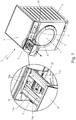
- reference number 1 indicates as a whole a front-loading home laundry washing machine which comprises: a preferably, though not necessarily, substantially parallelepiped-shaped, rigid outer boxlike casing 2 which is structured for resting on the floor; a preferably substantially cylindrical, bell-shaped hollow washing tub (not shown) which is arranged inside the casing 2 with its opening or mouth directly facing a laundry loading/unloading through opening realized in the front wall 3 of boxlike casing 2; and a substantially cylindrical, bell-shaped rotatable drum (not shown) which is structured for housing the laundry to be washed, and is housed in axially rotatable manner inside the washing tub so as to be able to freely rotate about its longitudinal reference axis.
- the laundry loading/unloading opening is preferably realized on the front wall 3 of casing 2 substantially astride of the vertical center-plane of the casing 2, and the front opening or mouth of the washing tub (not shown) is preferably watertight connected to the laundry loading/unloading opening realized on front wall 3 by means of a preferably substantially cylindrical, connecting bellows (not shown) preferably having an elastically-deformable structure.
- washing tub (not shown) is preferably suspended in floating manner inside the casing 2 and is preferably also arranged inside the boxlike casing 2 with its longitudinal reference axis L substantially horizontally-oriented, i.e. substantially perpendicular to front wall 3.
- the rotatable drum (not shown), in turn, is housed in axially rotating manner inside the washing tub (not shown) with its front opening directly faced/aligned to the laundry loading/unloading opening on front wall 3, and the drum rotation axis is preferably arranged locally substantially coincident with the horizontally-oriented longitudinal reference axis L of the washing tub.
- the front-loading laundry washing machine 1 furthermore comprises:
- the laundry washing machine 1 comprises an appliance control panel 6 which is structured for allowing the user to manually select the desired washing-cycle, and which is located on front wall 3 of casing 2, above the laundry loading/ unloading opening and substantially immediately beneath the preferably substantially horizontally oriented, upper worktop or top wall 7 of the same casing 2.
- the detergent dispensing assembly 5 is preferably housed inside the casing 2 above the washing tub (not shown), i.e. between the upper worktop 7 of casing 2 and the washing tub (not shown), and is structured for selectively feeding into the beneath located washing tub (not shown) a manually measured and pre-loaded amount of detergent, softener and/or other washing agent sufficient for performing only a single washing cycle.
- the detergent dispensing assembly 5 is a single-dose detergent dispenser.
- the detergent dispensing assembly 5 comprises a detergent drawer 10 which is manually fillable with a quantity of detergent, softener and/or other washing agent sufficient for performing only a single washing cycle, and which is fitted/ inserted in manually extractable manner into a corresponding, completely recessed, drawer housing 11 which extends preferably substantially horizontally inside the boxlike casing 2 while remaining beneath the upper worktop or top wall 7 and above the washing tub (not shown), and communicates with the outside of casing 2 via a front entrance or opening 11a which is realized on front wall 3 of casing 2 above the laundry loading/unloading opening and underneath the upper worktop or top wall 7 of the casing 2.
- the drawer housing 11 is completely recessed inside the casing 2, immediately beneath the upper worktop or top wall 7 of casing 2, so as to locate its front entrance or opening 11a on front wall 3 immediately beneath the front side edge of the upper worktop or top wall 7 of the same casing 2.
- the detergent drawer 10 is preferably movable inside the drawer housing 11 along a preferably substantially horizontally-oriented, displacement direction between a retracted position (see Figure 2 ) in which the detergent drawer 10 is completely recessed inside the drawer housing 11, i.e. inside the casing 2, preferably while at same time closing the front entrance or opening 11a of the drawer housing 11; and a completely extracted position (see Figure 1 ) in which the detergent drawer 10 partly juts out from the front wall 3 of casing 2 through the front entrance or opening 11a of the drawer housing 11 so as to allow easy manual refilling of the same detergent drawer 10.
- the detergent drawer 10 is preferably movable inside the drawer housing 11 along a substantially horizontally-oriented, displacement direction which is locally substantially perpendicular to the front wall 3 of casing 2.
- the drawer housing 11 also has a substantially basin-shaped bottom portion (not shown) which directly communicates with the inside of the beneath located washing tub via a suitable connecting duct (not shown), and the detergent dispensing assembly 5 preferably additionally comprises a further water supply circuit (not shown) which is connected or incorporated to the main fresh-water supply circuit, and is structured for selectively channeling/pouring, when the detergent drawer 10 is in the retracted position, a given amount of fresh water arriving from the water mains directly into the detergent drawer 10, so as to selectively flush/push the detergent, softener or other washing agent out of detergent drawer 10 and down on the bottom of the drawer housing 11.
- This mixture of water and detergent, softener or other washing agent afterwards flows into the washing tub via the connecting duct (not shown) branching off from the basin-shaped bottom of drawer housing 11.
- the detergent drawer 10 is preferably divided into a number/plurality of detergent compartments 10a (three detergent compartments in the example shown) each of which is manually fillable with a respective given quantity of detergent, softener or other washing agent sufficient for performing a single washing cycle; and the water supply circuit of the detergent dispensing assembly 5 is preferably structured for spilling/pouring the fresh water arriving from the main fresh-water supply circuit (not shown) selectively and alternatively into any one of the detergent compartments 10a of detergent drawer 10, so as to selectively flush the detergent, softener or other washing agent out of the same detergent compartment 10a and down onto the bottom of drawer housing 11.
- the water supply circuit of the detergent dispensing assembly 5 is preferably structured for selectively spilling/ pouring a dense shower of water droplets by gravity directly into any one of the detergent compartments 10a of detergent drawer 10, so as to flush the detergent, softener or other washing agent out of the detergent comportment 10a and down onto the bottom of drawer housing 11.
- the laundry washing machine 1 is additionally provided with a drawer-like supporting structure 13 which is fitted/ inserted in extractable manner into a corresponding, completely recessed, drawer housing 14 which extends preferably substantially horizontally inside the casing 2 while remaining beneath the upper worktop or top wall 7 and above the washing tub (not shown).
- Drawer housing 14 moreover communicates with the outside of casing 2 via a front entrance or opening 14a which is realized on front wall 3 of casing 2 above the laundry loading/unloading opening and beneath the upper worktop or top wall 7 of the casing 2, and the appliance control panel 6 is located/arranged on a front side of the drawer-like supporting structure 13.
- the drawer housing 14 communicates with the outside of casing 2 via a front entrance or opening 14a which is realized on front wall 3, above the laundry loading/unloading opening and beneath the upper worktop or top wall 7 of casing 2, and preferably also horizontally beside the front entrance or opening 11a of drawer housing 11.
- the drawer housing 14 is completely recessed inside the casing 2, immediately beneath the upper worktop or top wall 7 of casing 2, so as to locate its front entrance or opening 14a on the front wall 3 of casing 2, immediately beneath the front side edge of the upper worktop or top wall 7 of casing 2 and beside the front entrance or opening 11a of drawer housing 11.
- the detergent dispensing assembly 5 is therefore located inside the casing 2 horizontally beside the drawer-like supporting structure 13 and the corresponding completely recessed, drawer housing 14.
- the drawer housing 11 of the detergent dispensing assembly 5 is preferably arranged inside the casing 2 so as to locate its front entrance or opening 11a immediately beneath the upper worktop or top wall 7 of casing 2, approximately at the upper left corner of front wall 3; whereas the drawer housing 14 of the drawer-like supporting structure 13 is preferably arranged inside the boxlike casing 2 so as to locate its front entrance or opening 14a immediately beneath the upper worktop or top wall 7 of casing 2 and beside the front entrance or opening 11a of drawer housing 11, approximately at the upper right corner of front wall 3.
- the front entrance or opening 14a of drawer housing 14 is moreover immediately adjacent to the front entrance or opening 11a of drawer housing 11 and extends beneath the worktop or top wall 7 of casing 2, from the front entrance or opening 11a of drawer housing 11 substantially up to the right sidewall of the same casing 2, i.e. beneath the remaining portion of the front side edge of the upper worktop or top wall 7 of casing 2.
- the drawer-like supporting structure 13 directly supports the appliance control panel 6 and is movable inside the drawer housing 14 along a preferably substantially horizontally-oriented, displacement direction d between
- the drawer-like supporting structure 13 is preferably fitted/inserted in manually extractable manner into the completely recessed drawer housing 14, and is movable inside the drawer housing 14 along a substantially horizontally-oriented, displacement direction d which is preferably locally substantially perpendicular to front wall 3 of casing 2, and is therefore locally substantially parallel to the displacement direction of the detergent drawer 10 of the one-cycle detergent dispenser 8.
- the appliance control panel 6, in turn, is preferably powered via a power cable or via electromagnetic induction and moreover preferably communicates with the electronic central control unit (not shown) of the laundry washing machine 1 via cable or wireless.
- the front-loading laundry washing machine 1 is furthermore provided with an auxiliary, manually-operated, garment cleaning assembly 15 which comprises an electrically-powered, hand-held, substantially pen-shaped, garment stain-removal tool 16 and is arranged/located into the drawer-like supporting structure 13, behind the appliance control panel 6, so as to be closed/recessed inside the casing 2 when the drawer-like supporting structure 13 is arranged in the retracted position (see Figure 1 ).
- an auxiliary, manually-operated, garment cleaning assembly 15 which comprises an electrically-powered, hand-held, substantially pen-shaped, garment stain-removal tool 16 and is arranged/located into the drawer-like supporting structure 13, behind the appliance control panel 6, so as to be closed/recessed inside the casing 2 when the drawer-like supporting structure 13 is arranged in the retracted position (see Figure 1 ).
- the pen-shaped, garment stain-removal tool 16 is placed in easy manually seizable manner into a corresponding upper storage compartment 17 realized/provided on the drawer-like supporting structure 13, behind the appliance control panel 6.
- the drawer-like supporting structure 13 therefore directly supports also the pen-shaped, garment stain-removal tool 16 and is movable in a preferably substantially horizontally-oriented, displacement direction d between
- the pen-shaped, garment stain-removal tool 16 of the auxiliary garment cleaning assembly 15 preferably includes an electrically-powered, hand-held, substantially pen-shaped, ultrasonic garment stain-removal tool 16 which is preferably provided, at its tip portion, with a sound emitter capable of emitting ultrasonic waves that can be used for treating the stained portion/s of the garment preferably in combination with a process fluid, such as, for example, fresh water and/or a consumable stain-removal agent or other detergent agent suitable to be used with the pen-shaped ultrasonic garment stain-removal tool 16.
- a process fluid such as, for example, fresh water and/or a consumable stain-removal agent or other detergent agent suitable to be used with the pen-shaped ultrasonic garment stain-removal tool 16.
- the pen-shaped, garment stain-removal tool 16 of the auxiliary garment cleaning assembly 15 may alternatively includes an electrically-powered, hand-held, substantially pen-shaped, rubbing garment stain-removal tool 16 which is provided, at its tip portion, with a vibrating brush head which can be used for mechanically rubbing/brushing the stained portion/s of the garment preferably in combination with a process fluid, such as, for example, fresh water and/or a consumable stain-removal agent or other detergent agent suitable to be used with the pen-shaped rubbing garment stain-removal tool 16.
- a process fluid such as, for example, fresh water and/or a consumable stain-removal agent or other detergent agent suitable to be used with the pen-shaped rubbing garment stain-removal tool 16.
- the auxiliary garment cleaning assembly 15 preferably furthermore comprises a detergent reservoir 18 which is structured for receiving a given quantity (for example half a litre) of a consumable stain-removal agent or other detergent agent suitable to be used with the pen-shaped, garment stain-removal tool 16, i.e. a given quantity of process fluid.
- This detergent reservoir 18 is preferably arranged/located on a corresponding seat realized on the drawer-like supporting structure 13, so as to allow the user to easily load the stain-removal agent or other detergent agent into the same detergent reservoir 18 when the drawer-like supporting structure 13 is arranged in the completely extracted position.
- the detergent reservoir 18 is preferably housed into the drawer-like supporting structure 13 and the drawer-like supporting structure 13 is movable in a preferably substantially horizontally-oriented, displacement direction d between
- the pen-shaped, garment stain-removal tool 16 provided either with the sound emitter or the vibrating brush head is preferably, though not necessarily, also provided, preferably at its tip portion, with a nozzle capable of spaying onto the garment the process fluid to be used in combination with the same garment stain-removal tool 16 during treatment of the stained area of the garment, that is to say, for example, fresh water and/or a stain-removal agent or other detergent agent; and the auxiliary garment cleaning assembly 15 is preferably additionally provided with a supply line which is preferably at least partly arranged/ located on the drawer-like supporting structure 13, and is capable of channelling towards the garment stain-removal tool 16 a flow of one or more process fluids, preferably while controlling/regulating the flowrate of the/each process fluid towards the pen-shaped, garment stain-removal tool 16.
- the drawer-like supporting structure 13 therefore comprises at least part of the supply line of the auxiliary garment cleaning assembly 15.
- the pen-shaped, garment stain-removal tool 16 of the auxiliary garment cleaning assembly 15 could lack the sound emitter or the vibrating brush and be provided, at its tip portion, with the nozzle capable of spaying onto the garment a process fluid arriving through the supply line.
- the supply line of the garment cleaning assembly 15 preferably comprises: a detergent-agent supply circuit 19 which is at least partly arranged/located on the drawer-like supporting structure 13, and which is structured for channeling, on command, a flow of stain-removal agent or other detergent agent from the detergent reservoir 18 to the pen-shaped, garment stain-removal tool 16, preferably while controlling/regulating the flowrate of the detergent agent towards the pen-shaped, garment stain-removal tool 16; and optionally also a water supply circuit 20 which is at least partly arranged/located on the drawer-like supporting structure 13, and is structured for channeling, on command, a flow of fresh water into the detergent reservoir 18, preferably while controlling/regulating the flowrate of the fresh water towards the detergent reservoir 18.
- a detergent-agent supply circuit 19 which is at least partly arranged/located on the drawer-like supporting structure 13, and which is structured for channeling, on command, a flow of fresh water into the detergent reservoir 18, preferably while controlling/regulating the flowrate of the fresh water towards the detergent reservoir 18.
- the supply line of the garment cleaning assembly 15 preferably comprises an umbilical cable 21 having a flexible structure and which connects the pen-shaped, garment stain-removal tool 16 to the drawer-like supporting structure 13, and the detergent-agent supply circuit 19 is preferably at least party incorporated into the umbilical cable 21 so as to reach the pen-shaped, garment stain-removal tool 16.
- the supply line of the garment cleaning assembly 15 is furthermore structured to supply electric power to the pen-shaped, garment stain-removal tool 16.
- the supply line preferably comprises a power cable (not shown) structured for electrically powering the pen-shaped, garment stain-removal tool 16, and this power cable is preferably at least party incorporated into the umbilical cable 2.
- the pen-shaped, garment stain-removal tool 16 may also be powered by a battery pack housed inside the same pen-shaped, garment stain-removal tool 16.
- the drawer-like supporting structure 13 is preferably additionally provided with an auxiliary storage compartment structured for housing the supply line 21 when the garment stain-removal tool 16 rests inside the storage compartment 17.
- auxiliary storage compartment structured for housing the supply line 21 when the garment stain-removal tool 16 rests inside the storage compartment 17.
- storage compartment 17 is suitably shaped/dimensioned to accommodate both the pen-shaped, garment stain-removal tool 16 and the supply line 21.
- the detergent-agent supply circuit 19 preferably comprises a connecting hose or pipeline 23 which connects the detergent reservoir 18 to the pen-shaped, garment stain-removal tool 16, and which is preferably also structured so as to at least partially extend into the supply line 21 up to the pen-shaped, garment stain-removal tool 16; and an electrically-powered detergent feeding pump 24 which is preferably located/arranged on the drawer-like supporting structure 13, along the connecting hose or pipeline 23, and is structured for selectively sucking, from the detergent reservoir 18, the stain-removal agent or other detergent agent stored therein, and pumping/channeling said stain-removal agent or other detergent agent along said connecting hose or pipeline 23, towards the pen-shaped, garment stain-removal tool 16.
- the detergent feeding pump 24 is preferably a volumetric pump which is structured for selectively sucking a sequence of one or more basic amounts of stain-removal agent or other detergent agent from the detergent reservoir 18 and pumping/channeling said sequence of one or more basic amounts of stain-removal agent or other detergent agent towards the pen-shaped, garment stain-removal tool 16.
- the water supply circuit 20, is preferably connected or incorporated to the main fresh-water supply circuit (not shown) of the laundry washing machine 1, and preferably moreover comprises: a connecting hose or pipeline 25 which connects the detergent reservoir 18 to the fresh-water supply circuit (not shown) so as to channel the fresh water of the water mains towards the detergent reservoir 18; and preferably also an electrically-controlled, on-off valve 26 or similar which is arranged/ interposed between the fresh-water supply circuit and the connecting hose or pipeline 25, and is able to control/regulate the flow of fresh water along connecting hose or pipeline 25, towards the detergent reservoir 18.
- the supply line of the garment cleaning assembly 15 preferably additionally comprises a second water supply circuit 27 which is at least partly arranged/located on the drawer-like supporting structure 13, and which is structured for channeling, on command, a flow of fresh water to the pen-shaped, garment stain-removal tool 16, preferably while controlling/regulating the flowrate of the fresh water towards the pen-shaped, garment stain-removal tool 16.
- a second water supply circuit 27 which is at least partly arranged/located on the drawer-like supporting structure 13, and which is structured for channeling, on command, a flow of fresh water to the pen-shaped, garment stain-removal tool 16, preferably while controlling/regulating the flowrate of the fresh water towards the pen-shaped, garment stain-removal tool 16.
- the water supply circuit 27 is preferably connected or incorporated to the main fresh-water supply circuit (not shown) of the laundry washing machine 1. Alike the detergent-agent supply circuit 19, the water supply circuit 27 is moreover preferably at least party incorporated into the umbilical cable 21, so as to reach the pen-shaped, garment stain-removal tool 16 through the umbilical cable 21.
- the water supply circuit 27 preferably comprises a connecting hose or pipeline 28 which connects the fresh-water supply circuit (not shown) of the laundry washing machine 1 to the pen-shaped, garment stain-removal tool 16 so as to channel the fresh water of the water mains towards the pen-shaped, garment stain-removal tool 16, and which is preferably also structured so as to at least partially extend into the supply line 21 up to the pen-shaped, garment stain-removal tool 16; and preferably also an electrically-controlled, on-off valve 29 or similar which is arranged/interposed between the fresh-water supply circuit and the connecting hose or pipeline 28, and is able to control/regulate the flow of fresh water along connecting hose or pipeline 28, towards the pen-shaped, garment stain-removal tool 16.
- a connecting hose or pipeline 28 which connects the fresh-water supply circuit (not shown) of the laundry washing machine 1 to the pen-shaped, garment stain-removal tool 16 so as to channel the fresh water of the water mains towards the pen-shaped, garment stain
- functioning of detergent feeding pump 24, functioning of on-off valve 26, functioning of on-off valve 29, and/or switching on and off of the pen-shaped, garment stain-removal tool 16 is/are preferably controlled via corresponding manually-operated, push button/s 30 located on the pen-shaped, garment stain-removal tool 16.
- the detergent reservoir 18, in turn, preferably comprises: a preferably substantially parallelepiped-shaped, storage tank 31 which is structured for being manually fillable with a great quantity (for example half a litre) of consumable stain-removal agent or other detergent agent, and is located/incorporated into the drawer-like supporting structure 13 behind control panel 6, so as to be freely accessible by the user when the drawer-like supporting structure 13 is in the completely extracted position, and to be hidden and inaccessible by the user when the drawer-like supporting structure 13 is arranged in the retracted position; and a manually-removable cap 32 which is structured to close the storage tank 31, and is preferably located on top of storage tank 31 so as to be freely accessible by the user when the drawer-like supporting structure 13 is in the extracted position.
- a preferably substantially parallelepiped-shaped, storage tank 31 which is structured for being manually fillable with a great quantity (for example half a litre) of consumable stain-removal agent or other detergent agent, and is located/incorporated into the drawer-like supporting structure 13 behind
- the storage tank 31 is preferably arranged/located on the drawer-like supporting structure 13, behind the appliance control panel 6, so that at least the manually-removable cap 32 of storage tank 31 is freely accessible by the user when the drawer-like supporting structure 13 is arranged in the extracted position (see Figure 2 ), and is completely hidden and inaccessible by the user when the drawer-like supporting structure 13 is arranged in the retracted position.
- the manually-removable cap 32 allows the user to load the consumable stain-removal agent or other detergent agent inside the detergent reservoir 18, and therefore forms the exposable loading inlet or mouth of the detergent reservoir 18.
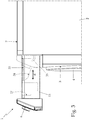
- the drawer-like supporting structure 13 is preferably moreover provided with a preferably substantially flat and preferably substantially horizontally-oriented working area 33 on which the user is allowed to spread the portion of the generic garment to be processed with the pen-shaped, garment stain-removal tool 16.
- the drawer-like supporting structure 13 is preferably provided with a preferably substantially flat and horizontally-oriented shelf portion 33 which is structured for supporting the stained portion of the generic garment to be processed with the pen-shaped, garment stain-removal tool 16.
- the shelf portion 33 of the drawer-like supporting structure 13 preferably has a perforated structure and is preferably underneath provided with a collector basin 34 which is structured for collecting the process fluid poured/sprayed on the garment during the use of the pen-shaped, garment stain-removal tool 16, i.e. the fresh water and/or consumable stain-removal agent or other detergent agent.
- the collector basin 34 preferably moreover communicates via a suitable drain pipeline 35 with the bottom of the washing tub (not shown) or directly with the drain sump (not shown) of the laundry washing machine 1 or with a generic drain line of the laundry washing machine 1, so as to channel the used process liquid, i.e. the used water and/or the used stain-removal agent or other detergent agent, into the drain pump of the laundry washing machine 1, or directly outside of the laundry washing machine 1.
- the used process liquid i.e. the used water and/or the used stain-removal agent or other detergent agent
- the laundry washing machine 1 is preferably, though not necessarily, additionally provided with:
- the auxiliary, manually-operated, garment cleaning assembly 15 when believes that a stain on a garment is difficult to remove solely with the washing cycle, the user can open the drawer-like supporting structure 13 and use the pen-shaped, garment stain-removal tool 16 for trying to remove the stain.
- the stain-removal treatment performed by the pen-shaped, garment stain-removal tool 16 basically consists in applying ultrasonic waves or mechanical friction onto a garment portion locally wetted with a suitable amount of water, stain-removal agent and/or other detergent agent.
- the user can arrange the drawer-like supporting structure 13 in the completely extracted position and use the pen-shaped, garment stain-removal tool 16 even when a washing cycle is taking place inside the laundry washing machine 1.
- auxiliary, manually-operated, garment cleaning assembly 15 on the drawer-like supporting structure 13, behind the appliance control panel 6, allows to maximise the use of the empty space inside the boxlike casing 2.
- the space behind the appliance control panel usually remains unused.
- the detergent dispensing assembly 5 is an auto-dosing detergent dispenser which is preferably located inside the casing 2, horizontally beside the drawer-like supporting structure 13 and the corresponding drawer housing 14, and is structured for automatically batching/dosing, on the basis of the selected washing cycle, the suitable amount/dose of detergent, softener and/or other washing agent to be used during the selected washing cycle and afterwards feeding said amount/dose of detergent, softener and/or other washing agent into the washing tub (not shown).
- the detergent drawer 10 is replaced by a second drawer-like supporting structure which is fitted/inserted in extractable manner into a corresponding, completely recessed, drawer housing that takes the place of drawer casing 11.
- This second drawer-like supporting structure houses/incorporates at least part of the auto-dosing detergent dispenser.
- the auto-dosing detergent dispenser may preferably comprise one or more detergent reservoirs each of which is structured for receiving a great quantity (for example half a litre or one litre) of detergent, softener and/or other washing agent sufficient for performing a great number of washing cycles; and one or more electrically-powered detergent feeding pumps (not shown) preferably of volumetric type, each of which is preferably structured for selectively sucking, from a corresponding detergent reservoir, the specific amount of the detergent, softener or other washing agent necessary and sufficient for performing the selected washing cycle, and pumping/ channelling said specific amount of the detergent, softener or other washing agent towards the washing tub.
- a great quantity for example half a litre or one litre
- electrically-powered detergent feeding pumps not shown
- volumetric type each of which is preferably structured for selectively sucking, from a corresponding detergent reservoir, the specific amount of the detergent, softener or other washing agent necessary and sufficient for performing the selected washing cycle, and pumping/ channelling said specific amount of the detergent, softener or other
- the supply line of the auxiliary garment cleaning assembly 15 lacks the water supply circuit 27, and instead comprises:
- the water supply circuit 39 preferably comprises a connecting hose or pipeline 41 which connects the water reservoir 38 to the connecting hose or pipeline 23 and/or directly to the pen-shaped, garment stain-removal tool 16 (and in the last case it is preferably also structured so as to at least partially extend into the supply line 21 up to the pen-shaped, garment stain-removal tool 16); and an electrically-powered water feeding pump 42 which is preferably located/arranged on the drawer-like supporting structure 13, along the connecting hose or pipeline 41, and is structured for selectively sucking, from the water reservoir 38, the fresh water stored therein and pumping/channeling said fresh water along said connecting hose or pipeline 41, towards the substantially pen-shaped, garment stain-removal tool 16.
- the water feeding pump 42 is preferably a volumetric pump which is structured for selectively sucking a sequence of one or more basic amounts of fresh water from the water reservoir 38 and pumping/ channeling said sequence of one or more basic amounts of fresh water towards the pen-shaped, garment stain-removal tool 16.
- Alike the detergent feeding pump 24, functioning of the water feeding pump 42 is preferably controlled via a corresponding manually-operated, push button 30 located on the pen-shaped, garment stain-removal tool 16.
- the water refilling circuit 40 is preferably connected or incorporated to the main fresh-water supply circuit (not shown) of the laundry washing machine 1, and preferably comprises: a connecting hose or pipeline 43 which connects the water reservoir 38 to the fresh-water supply circuit (not shown) so as to channel the fresh water of the water mains towards the water reservoir 38; and preferably also an electrically-controlled, on-off valve 44 or similar which is arranged/interposed between the fresh-water supply circuit and the connecting hose or pipeline 43, and is able to control/regulate the flow of fresh water along connecting hose or pipeline 43, towards the water reservoir 44.
- the water reservoir 38 preferably consists in a preferably substantially parallelepiped-shaped, closed storage tank 38 which is structured for storing a great quantity (for example half a litre) of fresh water.
- the water reservoir 38 may preferably comprise: a preferably substantially parallelepiped-shaped, storage tank which is structured for being manually fillable with a great quantity (for example half a litre) of fresh water, and is located into the drawer-like supporting structure 13 so to be freely accessible by the user when the drawer-like supporting structure 13 is in the completely extracted position, and to be hidden and inaccessible by the user when the drawer-like supporting structure 13 is arranged in the retracted position; and a manually-removable cap which is structured to close the storage tank, and is preferably located on top of the same storage tank so as to be freely accessible by the user when the drawer-like supporting structure 13 is in the extracted position.
- a preferably substantially parallelepiped-shaped, storage tank which is structured for being manually fillable with a great quantity (for example half a litre) of fresh water, and is located into the drawer-like supporting structure 13 so to be freely accessible by the user when the drawer-like supporting structure 13 is in the completely extracted position, and to be hidden and inaccessible by the user when the
- the detergent reservoir 18 and the water reservoir 38 may be recessed/housed in the drawer-like supporting structure 13 in a stable, though easily manually detachable manner, so as to allow the user to easily manually remove the detergent reservoir 18 and/or the water reservoir 38 from the drawer-like supporting structure 13 when the latter is arranged in the extracted position.
- This option allows the user to refill the detergent reservoir 18 and the water reservoir 38, if present, above the sink with all advantages concerned.
- the manually-removable detergent reservoir 18, i.e. tank 31 is connected to the detergent-agent supply circuit 19 and to the water supply circuit 20, if present, via a suitable number of self-closing hydraulic connectors; whereas the manually-removable water reservoir 38 is connected to the water supply circuit 39 and to the water refilling circuit 40, if present, via a suitable number of self-closing hydraulic connectors of known type.
Landscapes
- Engineering & Computer Science (AREA)
- Textile Engineering (AREA)
- Detail Structures Of Washing Machines And Dryers (AREA)
- Accessory Of Washing/Drying Machine, Commercial Washing/Drying Machine, Other Washing/Drying Machine (AREA)
Claims (16)
- Lave-linge (1) comprenant une coque extérieure (2), une cuve de lavage qui est agencée à l'intérieur de la coque (2) avec son ouverture ou bouche directement orientée vers une ouverture de chargement/déchargement de linge à laver réalisée sur la face avant (3) de la coque (2), un tambour rotatif qui est structuré pour loger le linge à laver et est logé de manière axialement rotative à l'intérieur de la cuve de lavage, un ensemble de distribution de détergent (5) qui est structuré pour fournir du détergent dans la cuve de lavage, un circuit d'approvisionnement principal en eau fraîche qui est structuré pour être raccordé aux conduites d'eau et pour canaliser de manière sélective un flux d'eau fraîche provenant des conduites d'eau vers l'ensemble de distribution de détergent (5) et/ou vers la cuve de lavage, et un panneau de commande d'appareil (6) qui est structuré pour permettre à l'utilisateur de sélectionner manuellement le cycle de lavage souhaité et qui est situé sur la face avant (3) de la coque (2) ;
l'ensemble de distribution de détergent (5) étant un distributeur de détergent à dose unique (5) structuré pour alimenter sélectivement la cuve de lavage avec une quantité de détergent, d'adoucissant et/ou d'un autre agent de lavage, mesurée manuellement et préchargée, suffisante pour réaliser un cycle de lavage unique, et qui comprend un tiroir à détergent (10) qui peut être rempli manuellement avec une quantité de détergent, adoucissant et/ou autre produit de lavage suffisante pour réaliser un cycle de lavage unique, et qui est monté/inséré de manière manuellement extractible dans un logement de tiroir correspondant (11) qui s'étend à l'intérieur de la coque (2) sous le plan de travail supérieur ou la face supérieure (7) de la coque (2), et communique avec l'extérieur par l'intermédiaire d'une entrée ou ouverture avant (11a) qui est réalisée sur la face avant (3) de la coque (2) au-dessus de l'ouverture de chargement/déchargement de linge à laver ;
le lave-linge (1) étant en outre muni d'un ensemble de nettoyage auxiliaire à commande manuelle (15), qui comprend un outil d'élimination de taches à moteur électrique portatif sensiblement en forme de stylo (16) et étant caractérisé en ce que le panneau de commande d'appareil (6) est situé/agencé sur un côté avant d'une structure portante de type tiroir (13) qui est montée/insérée de manière extractible dans un logement de tiroir correspondant (14) qui s'étend à l'intérieur de la coque (2) sous le plan de travail supérieur ou la face supérieure (7) de la coque (2), et communique avec l'extérieur par l'intermédiaire d'une entrée ou ouverture avant (14a) qui est réalisée sur la face avant (3) de la coque (2) au-dessus de l'ouverture de chargement/déchargement de linge à laver et horizontalement à côté de l'entrée ou ouverture avant (11a) du logement de tiroir (11) dudit tiroir à détergent (10) ; et en ce que l'outil d'élimination de taches à moteur électrique portatif sensiblement en forme de stylo (16) est placé de manière facilement saisissable à la main dans un compartiment de stockage correspondant (17) réalisé sur la structure portante de type tiroir (13) derrière le panneau de commande d'appareil (6) ; la structure portante de type tiroir (13) étant mobile à l'intérieur du logement de tiroir correspondant (14) entre une position rétractée dans laquelle la structure portante de type tiroir (13) est complètement encastrée à l'intérieur du boîtier (2) de manière à fermer l'outil d'élimination de taches (16) à l'intérieur de la coque (2) et à agencer le panneau de commande d'appareil (6) sensiblement coplanaire à la face avant (3) de la coque (2), et une position extraite dans laquelle la structure portante de type tiroir (13) fait partiellement saillie à partir de la face avant (3) de la coque (2) de manière à placer/agencer le compartiment de stockage (17) de l'outil d'élimination de taches (16) à l'extérieur de la coque (2) et à agencer le panneau de commande d'appareil (6) vers l'avant à l'écart de la face avant (3) de la coque (2). - Lave-linge selon la revendication 1, caractérisé en ce que l'ensemble de nettoyage auxiliaire à commande manuelle (15) comprend en outre une conduite d'alimentation (18, 19, 20, 27, 37, 38, 39, 40) qui est au moins partiellement agencée/située sur la structure portante de type tiroir (13) et qui capable de canaliser vers l'outil d'élimination de taches (16) un ou plusieurs fluides de traitement et/ou de fournir de l'énergie électrique.
- Lave-linge selon la revendication 1 ou 2, caractérisé en ce que l'outil d'élimination de taches (16) est un outil d'élimination de taches à moteur électrique portatif ultrasonore électrique sensiblement en forme de stylo (16), muni d'un émetteur sonore capable d'émettre des ondes ultrasonores.
- Lave-linge selon l'une quelconque des revendications précédentes, caractérisé en ce que l'ensemble de nettoyage auxiliaire à commande manuelle (15) comprend en outre un réservoir de détergent (18) qui est structuré pour recevoir une quantité donnée d'un agent détergent consommable approprié pour être utilisé avec l'outil d'élimination de taches (16), et est logé sur la structure portante de type tiroir (13) de manière à permettre à l'utilisateur de charger facilement l'agent détergent dans le même réservoir de détergent (18) lorsque la structure portante de type tiroir (13) est agencée dans la position extraite.
- Lave-linge selon la revendication 4, caractérisé en ce que ladite conduite d'alimentation comprend un circuit d'approvisionnement en agent détergent (19) qui est au moins partiellement agencé/situé sur la structure portante de type tiroir (13), et étant structuré pour canaliser, sur commande, un flux d'agent détergent à partir du réservoir de détergent (18) vers l'outil d'élimination de taches (16).
- Lave-linge selon la revendication 5, caractérisé en ce que le circuit d'approvisionnement en agent détergent (19) comprend une conduite de raccordement (23) qui raccorde le réservoir de détergent (18) à l'outil d'élimination de taches (16) ; et une pompe d'alimentation en détergent électrique (24) qui est située/agencée sur la structure portante de type tiroir (13), et est structurée pour aspirer sélectivement, à partir du réservoir de détergent (18), l'agent détergent qui est stocké à l'intérieur de celui-ci et pour pomper/canaliser ledit agent détergent le long de la conduite de raccordement (23), vers l'outil d'élimination de taches (16).
- Lave-linge selon la revendication 4, 5 ou 6, caractérisé en ce que ladite conduite d'alimentation comprend en outre un premier circuit d'approvisionnement en eau (20) qui est au moins partiellement agencé/situé sur la structure portante de type tiroir (13), et est structuré pour canaliser de manière sélective un flux d'eau fraîche dans le réservoir de détergent (18).
- Lave-linge selon l'une quelconque des revendications 2 à 7, caractérisé en ce que ladite conduite d'alimentation comprend en outre un second circuit d'approvisionnement en eau (27, 39) qui est au moins partiellement agencé/situé sur la structure portante de type tiroir (13), et est structuré pour canaliser, sur commande, un flux d'eau fraîche vers l'outil d'élimination de taches (16).
- Lave-linge selon la revendication 8, caractérisé en ce que le second circuit d'approvisionnement en eau (27, 39) comprend une conduite de raccordement (28) qui raccorde le circuit d'approvisionnement principal en eau fraîche du lave-linge (1) à l'outil d'élimination de taches (16), de manière à canaliser l'eau fraîche des conduites d'eau vers l'outil d'élimination de taches (16) ; et un ensemble de vannes à commande électrique (29) qui est agencé/intercalé entre le circuit d'approvisionnement principal en eau fraîche et la conduite de raccordement (28), et qui est capable de contrôler/réguler le flux d'eau fraîche le long de la conduite de raccordement (28) vers l'outil d'élimination de taches (16).
- Lave-linge selon la revendication 8, caractérisé en ce que ladite conduite d'alimentation comprend un réservoir d'eau (38) qui est structuré pour recevoir une grande quantité d'eau fraîche, et qui est logé sur la structure portante de type tiroir (13); et en ce que le second circuit d'approvisionnement en eau (39) comprend à son tour une conduite de raccordement (41) qui raccorde ledit réservoir d'eau (38) à l'outil d'élimination de taches (16), et une pompe d'alimentation en eau électrique (42) qui est située/agencée sur la structure portante de type tiroir (13), et est structurée pour aspirer sélectivement, à partir du réservoir d'eau (38), l'eau fraîche qui est stockée à l'intérieur de celui-ci et pour pomper/canaliser ladite eau fraîche le long de la conduite de raccordement (41) vers l'outil d'élimination de taches (16).
- Lave-linge selon l'une quelconque des revendications 2 à 10, caractérisé en ce que ladite conduite d'alimentation comprend un câble ombilical (21) ayant une structure souple et qui raccorde l'outil d'élimination de taches (16) à la structure portante de type tiroir (13).
- Lave-linge selon l'une quelconque des revendications 2 à 11, caractérisé en ce que ladite conduite d'alimentation est commandée par un ou plusieurs boutons-poussoirs (30) actionnés manuellement, situés sur l'outil d'élimination de taches sensiblement en forme de stylo (16).
- Lave-linge selon l'une quelconque des revendications précédentes, caractérisé en ce que la structure portante de type tiroir (13) est en outre munie d'une zone de travail (33) pour supporter le vêtement à traiter avec l'outil d'élimination de taches (16).
- Lave-linge selon l'une quelconque des revendications 4 à 13, caractérisé en ce que le réservoir de détergent (18) comprend un réservoir de stockage (31) qui est structuré pour pouvoir être rempli manuellement avec une grande quantité d'agent détergent, et est situé sur la structure portante de type tiroir (13) de manière à être librement accessible par l'utilisateur lorsque la structure portante de type tiroir (13) est dans la position extraite ; et un capuchon amovible manuellement (32) qui est structuré de manière à fermer le réservoir de stockage (31) et qui est situé sur le dessus du réservoir de stockage (31) de manière à être librement accessible pour l'utilisateur lorsque la structure portante de type tiroir (13) est dans la position extraite.
- Lave-linge selon l'une quelconque des revendications précédentes, caractérisé en ce que l'ensemble de distribution de détergent (5) est un distributeur de détergent à dosage automatique (5) structuré pour mesurer/doser automatiquement, sur la base du cycle de lavage sélectionné, la quantité/dose appropriée de détergent, d'adoucissant et/ou d'autre agent de lavage à utiliser pendant le cycle de lavage sélectionné, et qui est au moins partiellement logé/incorporé dans une seconde structure portante de type tiroir qui remplace ledit tiroir à détergent (10) et qui est montée/insérée de manière extractible dans un logement de tiroir complètement encastré correspondant qui remplace le logement de tiroir (11) du tiroir à détergent (10).
- Lave-linge selon l'une quelconque des revendications précédentes, caractérisé en ce qu'il comprend en outre : un élément de poussée qui est situé à l'intérieur du logement de tiroir (14) de la structure portante de type tiroir (13) et est structuré de manière à pousser élastiquement la structure portante de type tiroir (13) à l'écart de la position rétractée et vers la position extraite ; un mécanisme de verrouillage (36) qui est situé sur la structure portante de type tiroir (13), et est structuré pour atteindre et s'accrocher automatiquement de manière stable, bien que facilement libérable, sur la partie avant ou le tableau de bord du logement de tiroir (14) qui entoure/forme l'entrée ou l'ouverture avant (14a) du logement de tiroir (14) de la structure portante de type tiroir (13), de manière à maintenir la structure portante de type tiroir (13) dans la position rétractée et à empêcher l'élément de poussée de pousser la structure portante de type tiroir (13) à l'écart de la position rétractée ; et un bouton poussoir (37) actionné manuellement qui est situé sur le côté avant de la structure portante de type tiroir (13), et qui est structuré de manière à forcer, lorsqu'il est actionné manuellement, le mécanisme de verrouillage (36) pour libérer la structure portante de type tiroir (13) du logement de tiroir (14), permettant ainsi à l'élément poussoir de pousser la structure portante de type tiroir (13) à l'écart de la position rétractée.
Applications Claiming Priority (1)
| Application Number | Priority Date | Filing Date | Title |
|---|---|---|---|
| PCT/EP2013/063638 WO2014206485A1 (fr) | 2013-06-28 | 2013-06-28 | Lave-linge |
Publications (2)
| Publication Number | Publication Date |
|---|---|
| EP3014007A1 EP3014007A1 (fr) | 2016-05-04 |
| EP3014007B1 true EP3014007B1 (fr) | 2021-03-10 |
Family
ID=48700598
Family Applications (1)
| Application Number | Title | Priority Date | Filing Date |
|---|---|---|---|
| EP13732177.4A Active EP3014007B1 (fr) | 2013-06-28 | 2013-06-28 | Machine à laver |
Country Status (4)
| Country | Link |
|---|---|
| US (1) | US20160138207A1 (fr) |
| EP (1) | EP3014007B1 (fr) |
| BR (1) | BR112015032353B1 (fr) |
| WO (1) | WO2014206485A1 (fr) |
Families Citing this family (20)
| Publication number | Priority date | Publication date | Assignee | Title |
|---|---|---|---|---|
| EP3538704B1 (fr) * | 2016-11-08 | 2020-10-07 | Arçelik Anonim Sirketi | Un dispositif de nettoyage partiel destiné à être utilisé avec une machine à laver, un système de nettoyage du linge comprenant le dispositif de nettoyage partiel et une méthode de contrôle pour le fonctionnement du système de nettoyage du linge |
| US10584434B2 (en) | 2016-11-18 | 2020-03-10 | Midea Group Co., Ltd. | Stain removal tool for a laundry washing machine |
| US10767298B2 (en) | 2016-11-18 | 2020-09-08 | Midea Group Co., Ltd. | Stain removal tool for a laundry washing machine |
| CN106521885B (zh) * | 2016-12-26 | 2023-12-01 | 安徽纽创自动化装备有限公司 | 洗衣机中的溶解装置 |
| US10519587B2 (en) | 2017-02-27 | 2019-12-31 | Whirlpool Corporation | Laundry treating appliance detergent dispenser |
| US10519589B2 (en) | 2017-02-27 | 2019-12-31 | Whirlpool Corporation | Laundry treating appliance detergent dispenser |
| CN108505275B (zh) * | 2017-02-28 | 2020-12-01 | 青岛海尔洗衣机有限公司 | 一种衣物局部清洗结构及洗衣机 |
| US20190071814A1 (en) * | 2017-09-07 | 2019-03-07 | Haier Us Appliance Solutions, Inc. | Nozzle assembly for a washing machine appliance |
| US10633782B2 (en) | 2017-10-17 | 2020-04-28 | Haier Us Appliance Solutions, Inc. | Washing machine appliance spray hose assembly |
| US10865511B2 (en) * | 2017-11-15 | 2020-12-15 | Haier Us Appliance Solutions, Inc. | Nozzle assembly for a washing machine appliance |
| US10745849B2 (en) | 2018-02-02 | 2020-08-18 | Haier Us Appliance Solutions, Inc. | Nozzle assembly for a washing machine appliance |
| US10604878B2 (en) | 2018-02-19 | 2020-03-31 | Haier Us Appliance Solutions, Inc. | Washing machine appliance with a rotating docking station |
| US10760201B2 (en) | 2018-03-08 | 2020-09-01 | Haier Us Appliance Solutions, Inc. | Washing machine appliance with a retractable hose |
| US10907295B2 (en) | 2018-05-16 | 2021-02-02 | Haier Us Appliance Solutions, Inc. | Washing machine appliance and nozzle assembly |
| EP3617379B1 (fr) | 2018-08-30 | 2021-08-04 | Electrolux Appliances Aktiebolag | Appareil de traitement du linge comprenant un tiroir amélioré |
| US11060224B2 (en) | 2018-10-22 | 2021-07-13 | Whirlpool Corporation | Laundry treating appliance having a treating tool |
| US11155952B2 (en) * | 2018-10-31 | 2021-10-26 | Whirlpool Corporation | Laundry treating appliance having a stain treating station |
| CN111748960A (zh) * | 2019-03-26 | 2020-10-09 | 青岛海尔洗衣机有限公司 | 综合洗涤设备 |
| CN110714307A (zh) * | 2019-11-15 | 2020-01-21 | 珠海格力电器股份有限公司 | 洗涤剂投放装置、洗涤剂投放组件和洗衣机 |
| CA203403S (en) * | 2020-08-06 | 2022-06-23 | Lg Electronics Inc | Detergent drawer for washing machine |
Family Cites Families (6)
| Publication number | Priority date | Publication date | Assignee | Title |
|---|---|---|---|---|
| EP2309049A1 (fr) * | 2005-01-14 | 2011-04-13 | Electrolux Home Products Corporation N.V. | Appareil de traitement d'un article textile avec un dispositif de nettoyage par ultrason |
| GB0519046D0 (en) * | 2005-09-17 | 2005-10-26 | Reckitt Benckiser Uk Ltd | Improvements in and relating to cleaning |
| US7562543B2 (en) * | 2005-12-30 | 2009-07-21 | Whirlpool Corporation | Vertical laundry module with backsplash |
| ATE515591T1 (de) | 2006-05-26 | 2011-07-15 | Electrolux Home Prod Corp | Vorrichtung zum behandeln eines gewebeartikels mit einer ultraschallreinigungsvorrichtung |
| DE102008027726B3 (de) * | 2008-06-11 | 2009-10-29 | BSH Bosch und Siemens Hausgeräte GmbH | Hausgerät mit einer bewegbaren Bedienblende |
| ITAN20100018U1 (it) * | 2010-04-14 | 2011-10-15 | Antonio Merloni Spa In A S | Cassetto multifunzione ad apertura totale per elettrodomestici. |
-
2013
- 2013-06-28 EP EP13732177.4A patent/EP3014007B1/fr active Active
- 2013-06-28 US US14/901,359 patent/US20160138207A1/en not_active Abandoned
- 2013-06-28 WO PCT/EP2013/063638 patent/WO2014206485A1/fr active Application Filing
- 2013-06-28 BR BR112015032353-7A patent/BR112015032353B1/pt not_active IP Right Cessation
Non-Patent Citations (1)
| Title |
|---|
| None * |
Also Published As
| Publication number | Publication date |
|---|---|
| WO2014206485A1 (fr) | 2014-12-31 |
| BR112015032353A2 (pt) | 2017-07-25 |
| BR112015032353B1 (pt) | 2021-07-06 |
| US20160138207A1 (en) | 2016-05-19 |
| EP3014007A1 (fr) | 2016-05-04 |
Similar Documents
| Publication | Publication Date | Title |
|---|---|---|
| EP3014007B1 (fr) | Machine à laver | |
| EP3071742B1 (fr) | Machine à laver le linge avec tiroir à détergent comprenant un panneau de commande | |
| KR101466522B1 (ko) | 자동 계량공급 시스템을 구비한 물 사용 가전 기기 및 자동 계량공급 방법 | |
| EP3014009B1 (fr) | Machine à laver | |
| US9828720B2 (en) | Laundry washing machine with a water softening device | |
| US9903062B2 (en) | Laundry washing machine | |
| EP2959050B1 (fr) | Machine à laver le linge | |
| JP2024026813A (ja) | 洗濯機 | |
| JP2022190019A (ja) | 洗濯機 | |
| JP2009517111A (ja) | 洗浄機器 | |
| EP2841636B1 (fr) | Machine à laver le linge | |
| EP2954112B1 (fr) | Machine à laver le linge comprenant un dispositif adoucisseur d'eau | |
| WO2014121830A1 (fr) | Machine à laver le linge | |
| JP7496488B2 (ja) | 食器洗い機 |
Legal Events
| Date | Code | Title | Description |
|---|---|---|---|
| PUAI | Public reference made under article 153(3) epc to a published international application that has entered the european phase |
Free format text: ORIGINAL CODE: 0009012 |
|
| 17P | Request for examination filed |
Effective date: 20160128 |
|
| AK | Designated contracting states |
Kind code of ref document: A1 Designated state(s): AL AT BE BG CH CY CZ DE DK EE ES FI FR GB GR HR HU IE IS IT LI LT LU LV MC MK MT NL NO PL PT RO RS SE SI SK SM TR |
|
| AX | Request for extension of the european patent |
Extension state: BA ME |
|
| DAX | Request for extension of the european patent (deleted) | ||
| REG | Reference to a national code |
Ref country code: DE Ref legal event code: R079 Ref document number: 602013076169 Country of ref document: DE Free format text: PREVIOUS MAIN CLASS: D06F0039000000 Ipc: D06F0034280000 |
|
| RIC1 | Information provided on ipc code assigned before grant |
Ipc: D06F 29/00 20060101ALN20200911BHEP Ipc: D06F 43/00 20060101ALN20200911BHEP Ipc: D06F 34/28 20200101AFI20200911BHEP |
|
| GRAP | Despatch of communication of intention to grant a patent |
Free format text: ORIGINAL CODE: EPIDOSNIGR1 |
|
| STAA | Information on the status of an ep patent application or granted ep patent |
Free format text: STATUS: GRANT OF PATENT IS INTENDED |
|
| INTG | Intention to grant announced |
Effective date: 20201026 |
|
| RAP1 | Party data changed (applicant data changed or rights of an application transferred) |
Owner name: ELECTROLUX APPLIANCES AKTIEBOLAG |
|
| GRAS | Grant fee paid |
Free format text: ORIGINAL CODE: EPIDOSNIGR3 |
|
| GRAA | (expected) grant |
Free format text: ORIGINAL CODE: 0009210 |
|
| STAA | Information on the status of an ep patent application or granted ep patent |
Free format text: STATUS: THE PATENT HAS BEEN GRANTED |
|
| AK | Designated contracting states |
Kind code of ref document: B1 Designated state(s): AL AT BE BG CH CY CZ DE DK EE ES FI FR GB GR HR HU IE IS IT LI LT LU LV MC MK MT NL NO PL PT RO RS SE SI SK SM TR |
|
| REG | Reference to a national code |
Ref country code: GB Ref legal event code: FG4D |
|
| REG | Reference to a national code |
Ref country code: AT Ref legal event code: REF Ref document number: 1369901 Country of ref document: AT Kind code of ref document: T Effective date: 20210315 Ref country code: CH Ref legal event code: EP |
|
| REG | Reference to a national code |
Ref country code: DE Ref legal event code: R096 Ref document number: 602013076169 Country of ref document: DE |
|
| REG | Reference to a national code |
Ref country code: IE Ref legal event code: FG4D |
|
| REG | Reference to a national code |
Ref country code: LT Ref legal event code: MG9D |
|
| PG25 | Lapsed in a contracting state [announced via postgrant information from national office to epo] |
Ref country code: BG Free format text: LAPSE BECAUSE OF FAILURE TO SUBMIT A TRANSLATION OF THE DESCRIPTION OR TO PAY THE FEE WITHIN THE PRESCRIBED TIME-LIMIT Effective date: 20210610 Ref country code: NO Free format text: LAPSE BECAUSE OF FAILURE TO SUBMIT A TRANSLATION OF THE DESCRIPTION OR TO PAY THE FEE WITHIN THE PRESCRIBED TIME-LIMIT Effective date: 20210610 Ref country code: LT Free format text: LAPSE BECAUSE OF FAILURE TO SUBMIT A TRANSLATION OF THE DESCRIPTION OR TO PAY THE FEE WITHIN THE PRESCRIBED TIME-LIMIT Effective date: 20210310 Ref country code: HR Free format text: LAPSE BECAUSE OF FAILURE TO SUBMIT A TRANSLATION OF THE DESCRIPTION OR TO PAY THE FEE WITHIN THE PRESCRIBED TIME-LIMIT Effective date: 20210310 Ref country code: FI Free format text: LAPSE BECAUSE OF FAILURE TO SUBMIT A TRANSLATION OF THE DESCRIPTION OR TO PAY THE FEE WITHIN THE PRESCRIBED TIME-LIMIT Effective date: 20210310 Ref country code: GR Free format text: LAPSE BECAUSE OF FAILURE TO SUBMIT A TRANSLATION OF THE DESCRIPTION OR TO PAY THE FEE WITHIN THE PRESCRIBED TIME-LIMIT Effective date: 20210611 |
|
| REG | Reference to a national code |
Ref country code: AT Ref legal event code: MK05 Ref document number: 1369901 Country of ref document: AT Kind code of ref document: T Effective date: 20210310 |
|
| REG | Reference to a national code |
Ref country code: NL Ref legal event code: MP Effective date: 20210310 |
|
| PG25 | Lapsed in a contracting state [announced via postgrant information from national office to epo] |
Ref country code: SE Free format text: LAPSE BECAUSE OF FAILURE TO SUBMIT A TRANSLATION OF THE DESCRIPTION OR TO PAY THE FEE WITHIN THE PRESCRIBED TIME-LIMIT Effective date: 20210310 Ref country code: LV Free format text: LAPSE BECAUSE OF FAILURE TO SUBMIT A TRANSLATION OF THE DESCRIPTION OR TO PAY THE FEE WITHIN THE PRESCRIBED TIME-LIMIT Effective date: 20210310 Ref country code: RS Free format text: LAPSE BECAUSE OF FAILURE TO SUBMIT A TRANSLATION OF THE DESCRIPTION OR TO PAY THE FEE WITHIN THE PRESCRIBED TIME-LIMIT Effective date: 20210310 |
|
| PG25 | Lapsed in a contracting state [announced via postgrant information from national office to epo] |
Ref country code: NL Free format text: LAPSE BECAUSE OF FAILURE TO SUBMIT A TRANSLATION OF THE DESCRIPTION OR TO PAY THE FEE WITHIN THE PRESCRIBED TIME-LIMIT Effective date: 20210310 |
|
| PG25 | Lapsed in a contracting state [announced via postgrant information from national office to epo] |
Ref country code: CZ Free format text: LAPSE BECAUSE OF FAILURE TO SUBMIT A TRANSLATION OF THE DESCRIPTION OR TO PAY THE FEE WITHIN THE PRESCRIBED TIME-LIMIT Effective date: 20210310 Ref country code: EE Free format text: LAPSE BECAUSE OF FAILURE TO SUBMIT A TRANSLATION OF THE DESCRIPTION OR TO PAY THE FEE WITHIN THE PRESCRIBED TIME-LIMIT Effective date: 20210310 Ref country code: SM Free format text: LAPSE BECAUSE OF FAILURE TO SUBMIT A TRANSLATION OF THE DESCRIPTION OR TO PAY THE FEE WITHIN THE PRESCRIBED TIME-LIMIT Effective date: 20210310 Ref country code: AT Free format text: LAPSE BECAUSE OF FAILURE TO SUBMIT A TRANSLATION OF THE DESCRIPTION OR TO PAY THE FEE WITHIN THE PRESCRIBED TIME-LIMIT Effective date: 20210310 |
|
| PG25 | Lapsed in a contracting state [announced via postgrant information from national office to epo] |
Ref country code: PL Free format text: LAPSE BECAUSE OF FAILURE TO SUBMIT A TRANSLATION OF THE DESCRIPTION OR TO PAY THE FEE WITHIN THE PRESCRIBED TIME-LIMIT Effective date: 20210310 Ref country code: PT Free format text: LAPSE BECAUSE OF FAILURE TO SUBMIT A TRANSLATION OF THE DESCRIPTION OR TO PAY THE FEE WITHIN THE PRESCRIBED TIME-LIMIT Effective date: 20210712 Ref country code: ES Free format text: LAPSE BECAUSE OF FAILURE TO SUBMIT A TRANSLATION OF THE DESCRIPTION OR TO PAY THE FEE WITHIN THE PRESCRIBED TIME-LIMIT Effective date: 20210310 Ref country code: SK Free format text: LAPSE BECAUSE OF FAILURE TO SUBMIT A TRANSLATION OF THE DESCRIPTION OR TO PAY THE FEE WITHIN THE PRESCRIBED TIME-LIMIT Effective date: 20210310 Ref country code: IS Free format text: LAPSE BECAUSE OF FAILURE TO SUBMIT A TRANSLATION OF THE DESCRIPTION OR TO PAY THE FEE WITHIN THE PRESCRIBED TIME-LIMIT Effective date: 20210710 Ref country code: RO Free format text: LAPSE BECAUSE OF FAILURE TO SUBMIT A TRANSLATION OF THE DESCRIPTION OR TO PAY THE FEE WITHIN THE PRESCRIBED TIME-LIMIT Effective date: 20210310 |
|
| REG | Reference to a national code |
Ref country code: DE Ref legal event code: R097 Ref document number: 602013076169 Country of ref document: DE |
|
| PLBE | No opposition filed within time limit |
Free format text: ORIGINAL CODE: 0009261 |
|
| STAA | Information on the status of an ep patent application or granted ep patent |
Free format text: STATUS: NO OPPOSITION FILED WITHIN TIME LIMIT |
|
| PG25 | Lapsed in a contracting state [announced via postgrant information from national office to epo] |
Ref country code: DK Free format text: LAPSE BECAUSE OF FAILURE TO SUBMIT A TRANSLATION OF THE DESCRIPTION OR TO PAY THE FEE WITHIN THE PRESCRIBED TIME-LIMIT Effective date: 20210310 Ref country code: AL Free format text: LAPSE BECAUSE OF FAILURE TO SUBMIT A TRANSLATION OF THE DESCRIPTION OR TO PAY THE FEE WITHIN THE PRESCRIBED TIME-LIMIT Effective date: 20210310 Ref country code: MC Free format text: LAPSE BECAUSE OF FAILURE TO SUBMIT A TRANSLATION OF THE DESCRIPTION OR TO PAY THE FEE WITHIN THE PRESCRIBED TIME-LIMIT Effective date: 20210310 |
|
| REG | Reference to a national code |
Ref country code: CH Ref legal event code: PL |
|
| 26N | No opposition filed |
Effective date: 20211213 |
|
| PG25 | Lapsed in a contracting state [announced via postgrant information from national office to epo] |
Ref country code: SI Free format text: LAPSE BECAUSE OF FAILURE TO SUBMIT A TRANSLATION OF THE DESCRIPTION OR TO PAY THE FEE WITHIN THE PRESCRIBED TIME-LIMIT Effective date: 20210310 |
|
| REG | Reference to a national code |
Ref country code: BE Ref legal event code: MM Effective date: 20210630 |
|
| PG25 | Lapsed in a contracting state [announced via postgrant information from national office to epo] |
Ref country code: LU Free format text: LAPSE BECAUSE OF NON-PAYMENT OF DUE FEES Effective date: 20210628 |
|
| PG25 | Lapsed in a contracting state [announced via postgrant information from national office to epo] |
Ref country code: LI Free format text: LAPSE BECAUSE OF NON-PAYMENT OF DUE FEES Effective date: 20210630 Ref country code: IT Free format text: LAPSE BECAUSE OF FAILURE TO SUBMIT A TRANSLATION OF THE DESCRIPTION OR TO PAY THE FEE WITHIN THE PRESCRIBED TIME-LIMIT Effective date: 20210310 Ref country code: IE Free format text: LAPSE BECAUSE OF NON-PAYMENT OF DUE FEES Effective date: 20210628 Ref country code: CH Free format text: LAPSE BECAUSE OF NON-PAYMENT OF DUE FEES Effective date: 20210630 |
|
| PG25 | Lapsed in a contracting state [announced via postgrant information from national office to epo] |
Ref country code: IS Free format text: LAPSE BECAUSE OF FAILURE TO SUBMIT A TRANSLATION OF THE DESCRIPTION OR TO PAY THE FEE WITHIN THE PRESCRIBED TIME-LIMIT Effective date: 20210710 |
|
| PG25 | Lapsed in a contracting state [announced via postgrant information from national office to epo] |
Ref country code: BE Free format text: LAPSE BECAUSE OF NON-PAYMENT OF DUE FEES Effective date: 20210630 |
|
| PGFP | Annual fee paid to national office [announced via postgrant information from national office to epo] |
Ref country code: GB Payment date: 20220627 Year of fee payment: 10 Ref country code: DE Payment date: 20220620 Year of fee payment: 10 |
|
| PGFP | Annual fee paid to national office [announced via postgrant information from national office to epo] |
Ref country code: FR Payment date: 20220628 Year of fee payment: 10 |
|
| PG25 | Lapsed in a contracting state [announced via postgrant information from national office to epo] |
Ref country code: HU Free format text: LAPSE BECAUSE OF FAILURE TO SUBMIT A TRANSLATION OF THE DESCRIPTION OR TO PAY THE FEE WITHIN THE PRESCRIBED TIME-LIMIT; INVALID AB INITIO Effective date: 20130628 |
|
| PG25 | Lapsed in a contracting state [announced via postgrant information from national office to epo] |
Ref country code: CY Free format text: LAPSE BECAUSE OF FAILURE TO SUBMIT A TRANSLATION OF THE DESCRIPTION OR TO PAY THE FEE WITHIN THE PRESCRIBED TIME-LIMIT Effective date: 20210310 |
|
| P01 | Opt-out of the competence of the unified patent court (upc) registered |
Effective date: 20230625 |
|
| REG | Reference to a national code |
Ref country code: DE Ref legal event code: R119 Ref document number: 602013076169 Country of ref document: DE |
|
| GBPC | Gb: european patent ceased through non-payment of renewal fee |
Effective date: 20230628 |
|
| PG25 | Lapsed in a contracting state [announced via postgrant information from national office to epo] |
Ref country code: MK Free format text: LAPSE BECAUSE OF FAILURE TO SUBMIT A TRANSLATION OF THE DESCRIPTION OR TO PAY THE FEE WITHIN THE PRESCRIBED TIME-LIMIT Effective date: 20210310 Ref country code: DE Free format text: LAPSE BECAUSE OF NON-PAYMENT OF DUE FEES Effective date: 20240103 Ref country code: GB Free format text: LAPSE BECAUSE OF NON-PAYMENT OF DUE FEES Effective date: 20230628 |
|
| PG25 | Lapsed in a contracting state [announced via postgrant information from national office to epo] |
Ref country code: FR Free format text: LAPSE BECAUSE OF NON-PAYMENT OF DUE FEES Effective date: 20230630 |