EP3013386B1 - Phiolenpräparationsanordnungen - Google Patents
Phiolenpräparationsanordnungen Download PDFInfo
- Publication number
- EP3013386B1 EP3013386B1 EP14739636.0A EP14739636A EP3013386B1 EP 3013386 B1 EP3013386 B1 EP 3013386B1 EP 14739636 A EP14739636 A EP 14739636A EP 3013386 B1 EP3013386 B1 EP 3013386B1
- Authority
- EP
- European Patent Office
- Prior art keywords
- spike
- drug delivery
- vial
- drug
- blood
- Prior art date
- Legal status (The legal status is an assumption and is not a legal conclusion. Google has not performed a legal analysis and makes no representation as to the accuracy of the status listed.)
- Not-in-force
Links
Images



Classifications
-
- A—HUMAN NECESSITIES
- A61—MEDICAL OR VETERINARY SCIENCE; HYGIENE
- A61M—DEVICES FOR INTRODUCING MEDIA INTO, OR ONTO, THE BODY; DEVICES FOR TRANSDUCING BODY MEDIA OR FOR TAKING MEDIA FROM THE BODY; DEVICES FOR PRODUCING OR ENDING SLEEP OR STUPOR
- A61M1/00—Suction or pumping devices for medical purposes; Devices for carrying-off, for treatment of, or for carrying-over, body-liquids; Drainage systems
- A61M1/36—Other treatment of blood in a by-pass of the natural circulatory system, e.g. temperature adaptation, irradiation ; Extra-corporeal blood circuits
- A61M1/3621—Extra-corporeal blood circuits
- A61M1/3643—Priming, rinsing before or after use
- A61M1/3644—Mode of operation
-
- A—HUMAN NECESSITIES
- A61—MEDICAL OR VETERINARY SCIENCE; HYGIENE
- A61M—DEVICES FOR INTRODUCING MEDIA INTO, OR ONTO, THE BODY; DEVICES FOR TRANSDUCING BODY MEDIA OR FOR TAKING MEDIA FROM THE BODY; DEVICES FOR PRODUCING OR ENDING SLEEP OR STUPOR
- A61M1/00—Suction or pumping devices for medical purposes; Devices for carrying-off, for treatment of, or for carrying-over, body-liquids; Drainage systems
- A61M1/34—Filtering material out of the blood by passing it through a membrane, i.e. hemofiltration or diafiltration
- A61M1/342—Adding solutions to the blood, e.g. substitution solutions
-
- A—HUMAN NECESSITIES
- A61—MEDICAL OR VETERINARY SCIENCE; HYGIENE
- A61M—DEVICES FOR INTRODUCING MEDIA INTO, OR ONTO, THE BODY; DEVICES FOR TRANSDUCING BODY MEDIA OR FOR TAKING MEDIA FROM THE BODY; DEVICES FOR PRODUCING OR ENDING SLEEP OR STUPOR
- A61M1/00—Suction or pumping devices for medical purposes; Devices for carrying-off, for treatment of, or for carrying-over, body-liquids; Drainage systems
- A61M1/36—Other treatment of blood in a by-pass of the natural circulatory system, e.g. temperature adaptation, irradiation ; Extra-corporeal blood circuits
- A61M1/3621—Extra-corporeal blood circuits
- A61M1/3643—Priming, rinsing before or after use
-
- A—HUMAN NECESSITIES
- A61—MEDICAL OR VETERINARY SCIENCE; HYGIENE
- A61M—DEVICES FOR INTRODUCING MEDIA INTO, OR ONTO, THE BODY; DEVICES FOR TRANSDUCING BODY MEDIA OR FOR TAKING MEDIA FROM THE BODY; DEVICES FOR PRODUCING OR ENDING SLEEP OR STUPOR
- A61M1/00—Suction or pumping devices for medical purposes; Devices for carrying-off, for treatment of, or for carrying-over, body-liquids; Drainage systems
- A61M1/36—Other treatment of blood in a by-pass of the natural circulatory system, e.g. temperature adaptation, irradiation ; Extra-corporeal blood circuits
- A61M1/3621—Extra-corporeal blood circuits
- A61M1/3643—Priming, rinsing before or after use
- A61M1/3644—Mode of operation
- A61M1/3646—Expelling the residual body fluid after use, e.g. back to the body
-
- A—HUMAN NECESSITIES
- A61—MEDICAL OR VETERINARY SCIENCE; HYGIENE
- A61M—DEVICES FOR INTRODUCING MEDIA INTO, OR ONTO, THE BODY; DEVICES FOR TRANSDUCING BODY MEDIA OR FOR TAKING MEDIA FROM THE BODY; DEVICES FOR PRODUCING OR ENDING SLEEP OR STUPOR
- A61M1/00—Suction or pumping devices for medical purposes; Devices for carrying-off, for treatment of, or for carrying-over, body-liquids; Drainage systems
- A61M1/36—Other treatment of blood in a by-pass of the natural circulatory system, e.g. temperature adaptation, irradiation ; Extra-corporeal blood circuits
- A61M1/3621—Extra-corporeal blood circuits
- A61M1/3643—Priming, rinsing before or after use
- A61M1/3644—Mode of operation
- A61M1/3649—Mode of operation using dialysate as priming or rinsing liquid
-
- A—HUMAN NECESSITIES
- A61—MEDICAL OR VETERINARY SCIENCE; HYGIENE
- A61M—DEVICES FOR INTRODUCING MEDIA INTO, OR ONTO, THE BODY; DEVICES FOR TRANSDUCING BODY MEDIA OR FOR TAKING MEDIA FROM THE BODY; DEVICES FOR PRODUCING OR ENDING SLEEP OR STUPOR
- A61M5/00—Devices for bringing media into the body in a subcutaneous, intra-vascular or intramuscular way; Accessories therefor, e.g. filling or cleaning devices, arm-rests
- A61M5/14—Infusion devices, e.g. infusing by gravity; Blood infusion; Accessories therefor
- A61M5/142—Pressure infusion, e.g. using pumps
- A61M5/145—Pressure infusion, e.g. using pumps using pressurised reservoirs, e.g. pressurised by means of pistons
-
- A—HUMAN NECESSITIES
- A61—MEDICAL OR VETERINARY SCIENCE; HYGIENE
- A61M—DEVICES FOR INTRODUCING MEDIA INTO, OR ONTO, THE BODY; DEVICES FOR TRANSDUCING BODY MEDIA OR FOR TAKING MEDIA FROM THE BODY; DEVICES FOR PRODUCING OR ENDING SLEEP OR STUPOR
- A61M5/00—Devices for bringing media into the body in a subcutaneous, intra-vascular or intramuscular way; Accessories therefor, e.g. filling or cleaning devices, arm-rests
- A61M5/14—Infusion devices, e.g. infusing by gravity; Blood infusion; Accessories therefor
- A61M2005/1401—Functional features
- A61M2005/1402—Priming
-
- A—HUMAN NECESSITIES
- A61—MEDICAL OR VETERINARY SCIENCE; HYGIENE
- A61M—DEVICES FOR INTRODUCING MEDIA INTO, OR ONTO, THE BODY; DEVICES FOR TRANSDUCING BODY MEDIA OR FOR TAKING MEDIA FROM THE BODY; DEVICES FOR PRODUCING OR ENDING SLEEP OR STUPOR
- A61M2205/00—General characteristics of the apparatus
- A61M2205/58—Means for facilitating use, e.g. by people with impaired vision
- A61M2205/583—Means for facilitating use, e.g. by people with impaired vision by visual feedback
- A61M2205/584—Means for facilitating use, e.g. by people with impaired vision by visual feedback having a color code
-
- A—HUMAN NECESSITIES
- A61—MEDICAL OR VETERINARY SCIENCE; HYGIENE
- A61M—DEVICES FOR INTRODUCING MEDIA INTO, OR ONTO, THE BODY; DEVICES FOR TRANSDUCING BODY MEDIA OR FOR TAKING MEDIA FROM THE BODY; DEVICES FOR PRODUCING OR ENDING SLEEP OR STUPOR
- A61M2205/00—General characteristics of the apparatus
- A61M2205/60—General characteristics of the apparatus with identification means
Definitions
- This disclosure relates to vial spiking assemblies and related methods.
- impurities and toxins are removed from the blood of a patient by drawing the blood out of the patient through a blood access site, typically via a catheter, and then passing the blood through an artificial kidney (often referred to as a "dialyzer").
- the artificial kidney includes microtubes that each separate a first conduit from a second conduit.
- a dialysis solution (often referred to as a "dialysate”) flows through the first conduit of the dialyzer while the patient's blood flows through the second conduits of the dialyzer, causing impurities and toxins to be transferred from the blood to the dialysate through the microtubes.
- the impurities and toxins can, for example, be removed from the blood by a diffusion process. After passing through the dialyzer, the purified blood is then returned to the patient.
- kidney failure When kidney failure is diagnosed, patients are typically given medication to help control the symptoms and slow the progress of damage to the kidneys. Patients with chronic kidney failure generally take drugs, such as iron supplements, to control the balance of minerals in the body.
- drugs such as iron supplements
- WO 2011/002853 describes drug vial spikes, fluid line sets, and related systems.
- a fluid line set includes a frame, multiple spikes extending from the frame, and multiple fluid lines connected to the frame.
- the frame is configured to hold the fluid lines in a spaced apart configuration.
- US 2010/0063445 describes a device to indicate priming of an infusion line that includes a luer cap or other component of the infusion system having an indicator surface covered by a membrane.
- the membrane exhibits a first visual characteristic, such as being opaque, when dry and exhibits a second characteristic, such as becoming less opaque, when wet.
- a first visual characteristic such as being opaque
- a second characteristic such as becoming less opaque
- indicia on the surface which may be provided on a rod at least partially covered by the membrane, becomes visible, thereby indicating an intravenous tube to which the luer cap is secured has been primed or is nearly primed.
- the indicator may alternately be employed at an upstream end of an infusion set, such as at the port of a medical bag providing a supply of fluid, to indicate a low level of fluid in the medical bag.
- a vial spiking assembly includes a vial adapter that includes a base, a spike extending from a central region of the base, a sidewall extending from the base and substantially surrounding the spike in which the base and the side wall at least partially define a cavity configured to receive a portion of a vial, a spike cover removably attachable to the spike.
- the spike cover includes a material configured to indicate when the material has been contacted with liquid.
- a method in another example, includes causing a priming fluid to flow through a drug delivery line of a dialysis system until the priming fluid contacts a material of a vial adapter assembly causing the material to indicate contact of the priming fluid with the vial adapter assembly and stopping the flow of priming fluid through the drug delivery line after the material indicates contact of the priming fluid with the vial adapter assembly.
- a dialysis system includes a dialysis machine including a blood pump and a drug pump, a blood line set including a blood line that can be operably connected to the blood pump and a drip chamber in fluid communication with the blood line, and a fluid line set including a fluid line that can be connected to the drip chamber of the blood line set and to a vial adapter.
- the vial adapter includes a base, a spike extending from a central region of the base, a sidewall extending from the base and substantially surrounding the spike in which the base and the side wall at least partially define a cavity configured to receive a portion of a vial, a spike cover removably attachable to the spike.
- the spike cover includes a material that is configured to indicate when the material has been contacted with liquid.
- Implementations can include one or more of the following features.
- the material is a color changing material that changes color when contacted by a liquid.
- the color changing material is a microporous material impregnated with at least one of the following: bromophenol blue, cobalt chloride, a food dye, powder dye, and a color additive.
- the microporous material is molded with a color additive that changes color when contacted with liquid.
- the microporous material has an average pore size capable of permitting air to flow therethrough and preventing liquid from flowing therethrough.
- the microporous material surrounds the spike when the spike cover is attached to the spike.
- the spike cover is movable away from the base from a first position wherein the cover at least partially covers a tip of the spike of the vial adapter to a second position wherein the tip of the vial adapter is fully exposed.
- the spike cover includes a housing defining a cavity in which the material is disposed.
- the housing is formed of a gas permeable material.
- the material is visible through the housing.
- the drug delivery line is connected to a vial adapter assembly comprising a vial adapter having a spike extending from a central region of a base, and a spike cover that can be removably attached to the spike.
- the spike cover includes the material.
- the microporous material has an average pore size of about 5 to 45 microns.
- causing the priming fluid to flow through the drug delivery line causes air in the drug delivery line to exit through the vial adapter assembly.
- the method further includes connecting the drug delivery line to a blood line set of the dialysis system before the priming fluid flows through the drug delivery line.
- the drug delivery line is connected to a drip chamber of the blood line set.
- causing the priming fluid to flow through the drug delivery line includes causing the priming fluid to flow to the drip chamber and overfill the drip chamber, and the overfilling of the drip chamber forces the priming fluid through the drug delivery line.
- causing the priming fluid to flow through the drug delivery line includes causing the priming fluid to flow from a priming fluid bag to the drip chamber, and from the drip chamber to a vial spiking assembly.
- the method further includes removing the spike cover after stopping the flow of priming fluid, inserting a drug vial onto the vial adapter assembly, and initiating drug delivery.
- initiating drug delivery comprises operating a drug delivery pump to cause drug from the drug vial to mix with a patient's blood prior to delivery of the blood to the patient.
- the drip chamber is downstream of the blood pump and the fluid line is connected to a top region of the drip chamber.
- the microporous material is covalently bonded with a color additive that changes color when contacted with liquid.
- the microporous material has an average pore size capable of permitting air to flow through and preventing liquid from flowing through.
- the drip chamber is downstream of the blood plump.
- the fluid line is connected to a top portion of the drip chamber.
- Implementations can include one or more of the following advantages.
- the vial spiking assemblies described herein are designed to be used in medical systems, such as hemodialysis systems. Priming the drug delivery line of such systems ensures that the already sterile drug delivery line set is fully filled with liquid, which blocks potential ingress points for pathogens. In addition, priming the drug delivery line set reduces the likelihood of air being delivered to the patient during treatment. These vial spiking assemblies improve the process of priming of the system by providing a clear and easily obtainable indication that the drug delivery line is fully primed. Further, by connecting the drug delivery line to the system, both the blood line set and the drug delivery line set can be primed using one pump (e.g., the blood pump) during priming.
- one pump e.g., the blood pump
- a hemodialysis system 101 includes a hemodialysis machine 100 having a drug delivery module 106 to which a drug delivery line set 149 is connected.
- the drug delivery module 106 and drug delivery line set 149 can be used to deliver drugs to a patient during hemodialysis treatment.
- the drugs can be delivered from a drug vial 111 through the drug delivery line set 149 to a drip chamber 136 of a blood line set 122 where the drug mixes with blood before the blood is returned to the patient.
- the drug delivery line set 149 can be primed with a priming fluid (e.g., saline from a priming fluid bag 168) prior to drug delivery.
- a priming fluid e.g., saline from a priming fluid bag 168
- a spike cover 138 (shown in Figs. 3-6 ) of the drug delivery line set 149 includes an indicator material that changes color when contacted by the priming fluid and indicates to the user that the drug delivery line set 149 has been successfully primed. This color change is monitored by a color change sensor 167 positioned on the drug delivery module 106 adjacent to the spike cover 138.
- the hemodialysis machine 100 includes a display 102 and a control panel 104, whereby the user selections and instructions can be sent to, and stored by, a control unit of the hemodialysis machine 100.
- the hemodialysis machine 100 also includes modules that house components used to perform hemodialysis, including the drug delivery module 106, a blood pump module 112, and a level detector module 114.
- the disposable blood line set 122 which forms a blood circuit, is connected to the modules 106, 112, and 114 on the front side of the hemodialysis machine 100.
- patient lines 116, 120 of the blood line set 122 are connected to the patient and a pump tubing segment 121 of the blood line set 122 is connected to a blood pump 107 of the blood pump module 112.
- blood pump 107 As the blood pump 107 is operated, blood is drawn from the patient, pumped through a dialyzer 109 and the drip chamber 136 of the blood line set 122, and then returned to the patient.
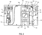
- Fig. 2 illustrates the mid-section of the hemodialysis machine 100 with the blood line set 122 and the drug delivery line set 149 connected to the modules 106, 112, and 114 and with a drug vial 111 inserted into a vial adapter 140 of the drug delivery line set 149.
- the blood line set 122 includes the pump tubing segment 121, which is connected to the blood pump module 112 in a manner so as to operatively engage the blood pump 107 of the blood pump module 112. Operation of the blood pump 107 pumps blood through the blood line set 122.
- the drip chamber 136 of the blood line set 122 is positioned at a location downstream from the blood pump 107.
- the drip chamber 136 permits gas, such as air, in the blood to escape from the blood before the blood is returned to a patient.
- the drip chamber 136 can be secured to the level detector module 114 so as to align with a fluid level detector 145 that is adapted to detect the level of liquid (e.g., blood and/or saline) within the drip chamber 136.
- a drug delivery line 146 of the drug delivery line set 149 is connected via a luer lock connector 150 to the blood line set 122 at a location between the dialyzer 109 and the drip chamber 136.
- the luer lock connector 150 is connected to a mating luer locking fitting on a level adjust line 135 that is connected to the top of the drip camber 136.
- a clamp 134 is attached to the level adjust line 135 and is used to permit or block fluid from passing between the drug delivery line set 149 and the blood line set 122.
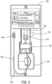
- Fig. 3 shows the drug delivery line set 149 connected to the drug delivery module 106 prior to connecting the drug delivery line 146 to the blood line set 122.
- the end of the drug delivery line 146 is connected to a storage clip 148 of the drug delivery module 106.
- the drug delivery line 146 passes through a peristaltic drug pump 144. Prior to use, a user would unclip the drug delivery line 146 from the storage clip 148 and connect it to the blood line set 122 in the manner shown in Figs. 1 and 2 .
- the drug delivery module 106 also includes the color change sensor 167 and a fluid flow detector 142.
- the color change sensor 167 is adjacent to the spike cover 138 and generates a signal and transmits the signal to a control unit (e.g., a processor) of the dialysis machine 100. Based on the received signal, the control unit can activate an indicator (e.g., an audible or visual device that indicates a color change has occurred) to signal the completion of the priming cycle.
- the color change sensor 167 is an optical sensor.
- the fluid flow detector 142 is capable of detecting air bubbles within the drug delivery line 146. As a result, the fluid flow detector 142 can determine whether the drug vial 111 is empty.
- the fluid flow detector 142 is an optical detector.
- the OPB 350 level detector made by Optek® can, for example, be used. Other types of optical detectors can alternatively or additionally be used. Similarly, other types of sensors, such as sensors utilizing ultrasound technology can be used as the fluid flow detector.
- the fluid flow detector 142 includes a sensor that, in addition to sensing the presence of an air bubble within its associated drug delivery line 146, can sense the presence of the drug delivery line 146 itself.
- the drug delivery line 146 passes through (e.g., is threaded through) the peristaltic drug pump 144.
- the peristaltic drug pump 144 works by compressing the drug delivery line 146 and moving a "pillow" of fluid that is pinched between two points of the drug delivery line 146 by the pump rollers. Each "pillow” of fluid is of a volume determined by the roller spacing and the inside diameter of the drug delivery line 146.
- a series of these "pillow" shaped volumes of fluid are delivered to the drip chamber 136. The rate of fluid delivery can be changed by altering the speed of the peristaltic drug pump 144.
- the pump speed can be controlled, for example, by adjusting the voltage delivered to the peristaltic drug pump 144.
- the voltage delivered to the motor of the peristaltic drug pump 144 can, for example, be adjusted by the control unit (e.g., software of the control unit) until the correct speed (e.g., the speed that corresponds to the desired flow rate) is measured by an encoder of the peristaltic drug pump 144.
- the drug delivery line set 149 is fluidly connected to the blood circuit 122 of the hemodialysis system 101, as shown in Figs. 1 and 2 .
- Drugs are delivered to the drip chamber 136 using the drug delivery module 106.
- the drugs mix with the patient's blood within the drip chamber 136 and are then delivered to the patient along with the patient's filtered blood.
- the drug delivery line set 149 includes the vial adapter 140 to which the drug delivery line 146 is attached.
- the spike cover 138 is removably secured to the vial adapter 140 by an interference fit.
- the spike cover 138 is removed from the vial adapter 140 prior to use to allow a drug vial (e.g., the drug vial 111) to be inserted into the vial adapter 140.
- Fig. 5 illustrates the vial adapter assembly with the spike cover 138 removed from the vial adapter 140.
- the vial adapter 140 includes circumferentially spaced side wall segments 154 that extend upwardly from a base 155 to form a receiving cavity 158 sized and shaped to receive a drug vial.
- a spike 156 extends from a central region of the base 155 and is sized and shaped to pierce a seal of the drug vial when the drug vial is inserted into the receiving cavity 158.
- the spike 156 has a central passage in fluid communication with a cavity 157 of the spike cover 138 when the spike cover 138 is positioned over the spike 156.
- the circumferential side wall segments 154 of the vial adapter 140 extend to a slightly greater height than the spike 156 of the vial adapter 140. Adjacent side wall segments 154 are spaced apart by longitudinal/vertical slots 153. The side wall segments 154 together with the base 155 form the receiving cavity 158 that is configured to receive a portion of a drug vial (e.g., a collar of a drug vial cap assembly).
- a drug vial e.g., a collar of a drug vial cap assembly
- the receiving cavity 158 is configured to receive a collar having a diameter that is about 0.75 inches to about 1 inch (e.g., about 0.875 inches.)
- the side wall segments 154 are configured to deflect away from the longitudinal axis of the vial adapter 140 when a radially outward force is applied (e.g., as a result of the drug vial being inserted into the receiving cavity 158) and rebound towards the longitudinal axis when the force is released.
- protrusions 160 on side wall segments 154 of the vial adapter 140 help secure a vial within the receiving cavity 158 of the vial adapter 140.
- the extension of the side wall segments 154 to a slightly greater height that the spike 156 of the vial adapter 140 also help to ensure that the spike 156 is not inadvertently contacted (e.g., by the user) prior to loading of the drug vial 111 onto the spike 156. This can, for example, help to prevent the spike 156 from becoming contaminated before it is inserted into the drug vial.
- the spike 156 is formed of one or more medical grade plastics, such as PVC or acrylonitrile butadiene styrene (ABS).
- PVC polyvinyl styrene
- ABS acrylonitrile butadiene styrene
- other medical grade plastics can be used to form the spike 156.
- certain metals, such as stainless steel, could be used to form the drug vial spike 156.
- the spike cover 138 is placed into the receiving cavity 158 of the vial adapter 140 to cover the spike 156.
- the spike cover 138 can help prevent objects from contacting and contaminating the spike 156 prior to use and can also prevent users from inadvertently sticking themselves with the spike 156.
- the spike cover 138 is configured to be received in the receiving cavity 158 and temporarily retained by the side wall segments 154.
- the spike cover 138 can be retained via a loose interference fit.
- the side wall segments 154 provide a resisting force of about 0.75 lbf to about 2 lbf to retain the spike cover 138 when it is retained by the vial adapter 140.
- the base 155 of the vial adapter 140 is solid.
- the spike cover 138 is gas permeable and fluid impermeable.
- the spike cover 138 is made out of a microporous material (e.g., Polyethylene or high density Polyethylene) having a porosity of about 7 microns (e.g, 5 to about 45 microns).
- the microporous material of the spike cover 138 can withstand sufficient water intrusion pressure so as not to leak fluid, but is sufficiently porous to be gas permeable.
- this water intrusion pressure is about 200 mbar (2.90 psi) over 1 ⁇ 4 inch material thickness (i.e., the radial distance from the spike to the outer diameter of the cover).
- the spike cover 138 can be molded (e.g., using heat and/or pressure) or milled to the appropriate dimensions.
- the spike cover 138 forms the cavity 157, which is sized to create a seal between the cavity 157 and the spike 156 of the vial adapter 140 (e.g., by radial interference fit).
- the cavity 157 is also slightly longer than the exposed position of the spike 156 so that the tip of spike 156 is not damaged during use (e.g., when the spike cover is attached).
- the spike cover 138 is removably attached to the vial adapter 140 by an interference fit capable of resisting force generated by the priming system.
- the combination of the retaining strength of the vial adapter 140 and the sizing of the cavity 157 forms a seal that prevents leaking at the interface between the spike cover 138 and the vial adaptor 140.
- the microporous material of the spike cover 138 surrounds the spike 156.
- the microporous material inhibits the flow of liquid while allowing gases (e.g., air) to pass there through.
- gases e.g., air
- the microporous material of spike cover 138 is impregnated with color changing additives.
- the color changing additives can be incorporated during molding and/or surface coated. These additives are liquid sensitive and exhibit a physical change, e.g., change color, when they are contacted by liquid. This color change is visible through the microporous material of the spike cover 138.
- color changing additives examples include bromophenol blue, cobalt chloride, and food dye in powder or granular form. Other liquid triggered color changing materials are known in the art. These additives may also be used to create a film or liquid that is applied over, or covalently bonded to, the microporous material of the spike cover 138.
- the user Prior to hemodialysis, the user connects the drug delivery line set 149, which includes the vial adapter 140, the spike cover 138, and the drug delivery line 146, to the drug delivery module 106 of the dialysis machine 100.
- the drug delivery line set 149 is typically provided to the user in a sterile bag.
- the user To connect the drug delivery line set 149 to the drug delivery module 106, the user first opens the sterile bag and removes the drug delivery set 149.
- the user then opens a door 166 of the fluid flow detector 142, places vial adapter assembly (e.g., the vial adapter 140 and spike cover 138) into a vial holder 164, and threads the drug delivery line 146 through a fluid flow sensor 162 of the fluid flow detector 142 .
- vial adapter assembly e.g., the vial adapter 140 and spike cover 138
- the user then opens a door 167 of the peristaltic drug pump 144 and threads the drug delivery line 146 through the peristaltic drug pump 144.
- the door 167 remains open so that the drug delivery line 146 is not crimped between the door 167 and rollers of the drug pump 144. This permits fluid to flow freely through the drug delivery line 146.
- the drug delivery line 146 is then connected to the drip chamber 136 using an aseptic technique. As discussed above, this typically involves connecting the luer lock fitting 150 on an end of the drug delivery line 146 to a mating luer lock fitting on the level adjust line 135 extending from the drip chamber 136. However, other types of connectors can be used.
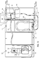
- the priming fluid bag 168 is connected to the blood line set 122 via a priming fluid line 169.
- the priming fluid bag 168 is connected to the priming fluid line 169 by a luer lock connection.
- the priming fluid line 169 also includes clamps 171 and 172 that are used to regulate the fluid flow from the fluid bag 168 to the blood line set 122.
- Fig. 9 after the drug delivery line set 149 has been connected to the drip chamber 136, which is attached to the level detector module 114, the patient lines 116 and 120 are connected by a luer connector 173 so as to form a closed circuit.
- the drug delivery line set 149 is now ready to be primed.
- the clamps 171 and 173 are released and gravity draws priming fluid (e.g, saline) from the fluid bag 168.
- the blood pump 107 then pumps the priming fluid through the blood line set 122 to the dialyzer 109 and then from the dialyzer 109 to the drip chamber 136.
- priming fluid e.g, saline
- the blood pump 107 pumps the priming fluid at a sufficient rate (e.g., 100-300mL/min) to overfill the drip chamber 136, despite a portion of the priming fluid continuing through line 120.
- the overfilling of the drip chamber 136 generates back pressure that causes the priming fluid to travel through the drug delivery line 146 towards the spike cover 138.
- the priming fluid flows from the drip chamber 136 toward the spike cover 138 of the vial adapter 140 via the drug delivery line 146.
- the priming fluid travels through the spike 156 (shown in Figs. 5 and 6 ) of the vial adapter 140, the priming fluid contacts the microporous material of the spike cover 138.
- any air remaining in the drug delivery line 146 is forced towards the drug vial adapter assembly and eventually out of the spike tip.
- the microporous spike cover material permits air to pass through the spike cover 138 while retaining the priming fluid within the system.
- the air exits the spike tip it passes through the microporous material of the spike cover 138 to the surrounding environment. This helps to ensure that no air is trapped within the system and thus helps to ensure efficient delivery of drug from the drug vial 111. Priming the drug delivery line set 149 in this way can also protect the ingress of pathogens via the vial adapter 140.
- the priming liquid After the air from the drug delivery line set 149 has exited the vial adapter 140 and drug delivery line 146, the priming liquid also exits the spike 156 of the vial adapter 140.
- the priming fluid then comes into contact with the color changing indicator material impregnated in the microporous material of the spike cover 138. A change in color of this indicator material indicates to the user that the priming cycle is complete, with respect to the drug delivery module 106.
- the sensor 167 adjacent to the spike cover 138 detects the color change and generates a signal when the priming cycle is complete. The signal is transmitted to the control unit and causes the control unit to activate an audible or visual indicator (e.g., using the display 102) to indicate the completion of the priming cycle.
- the clamps 171 and 172 are closed and the patient lines 116 and 120 are also clamped.
- the connection between the patient lines 116 and 120 is also severed in anticipation of connection to a patient.
- the door 167 of the peristaltic drug pump 144 is closed, and the spike cover 138 is removed.
- the drug vial 111 is placed on the vial adapter 140 so that the spike 156 pierces a seal of the drug vial 111 and places the vial in fluid connection with the drug delivery line set 149 (e.g., as shown in Figs 1 and 2 ).
- the peristaltic drug pump 144 is then operated to deliver drug to the drip chamber 136 of the blood line set 122.
- the volume of drug delivered to the patient is monitored and controlled by the control unit and the peristaltic drug pump 144 of the drug delivery device 106.
- the drip chamber 136 of the hemodialysis system 101 functions as an air trap.
- any gases e.g., air
- the drip chamber 136 provides other benefits.
- the drip chamber 136 provides visual confirmation of drug delivery and allows the delivered drug to mix with the patient's blood prior to reaching the patient.
- the drip chamber 136 allows for simple luer connection to the drug delivery line set 149. As a result, the patient need not be stuck with an additional needle in order to receive the drug from the drug vial 111.
- the vial adapter 140 may have fingers and side wall segments that project at a non-perpendicular angle from the base of the vial adapter so as to generate resisting forces as the vial is inserted into the vial adapter.
- the vial adapter may further include sidewalls that have a height that is less than that of the spike.
- the base of the vial adapter is generally shown as being solid, other configurations are possible.
- the base of the vial adapter may have one or more (e.g., 1, 2, 3, 4, 5, 6, 7, and 8) holes arranged around the spike. These one or more holes permit a fluid and/or air to flow in and out of the vial adapter.
- the material of the spike cover may be selected based on the presence and/or number of ventilation holes.
- the vial adapter contains ventilation holes
- the vial adapter can be provided with a gas impermeable spike cover since gasses are allowed to vent to the atmosphere via the ventilation holes and need not pass through the spike cover.
- the number of holes correlates with the number of wall segments arranged around the base, and the holes are typically aligned with the wall segments.
- the spike cover has been described as including a color changing material
- at least some portions of the vial adapter e.g., the base, the drug delivery line, and/or the spike, can alternatively or additionally include a color changing material that changes color when the portions are exposed to a liquid.
- the base, the drug delivery line, and/or the spike can include a coating impregnated with a color changing material.
- the base, the drug delivery line, and/or the spike can be made from a transparent or semi-transparent material so that when the coating undergoes a color change, the color change is visible to the user.
- the vial adapter is generally shown to include six sidewall segments, more, or fewer sidewall segments are possible.
- the sidewall of the vial adapter includes two, three, four, five, or more sidewall segments.
- the sidewall of the vial adapter includes only one continuous sidewall segment.
- the sidewall segments are generally shown to have protrusions to help secure the spike cover and/ or vial within the assembly, other securing means are possible.
- the sidewalls may not significantly deform when the spike cover and/or drug vial is inserted into or removed from the vial adapter.
- the sidewall segments provide a force to retain the spike cover and/or drug vial, they do not lockingly engage any mating features of the spike cover and/or drug vial. As a result, the spike cover and/or drug vial can be removed without damaging or altering the vial adapter.
- the vial and vial adapter devices have been described as having a generally circular cross-section, other shaped vials and/or vial spiking mechanisms are possible.
- the vial and/or the vial spiking device in particular, the interface between the vial and the drug vial spiking device, can have other cross-sectional shapes, such as an ellipse, a polygon (e.g., a rectangle, a square, a pentagon, a hexagon, or another polygon), or other structurally suitable shapes.
- drug vial assemblies have been shown as being substantially integral one-piece components, other configurations are possible.
- one or more portions of the drug vial devices e.g., the base, the spike, the sidewall segments, and/or the fingers
- the drug vial devices can be formed as separate components that can be attached to one another to form the drug vial spiking device.
- a tip region of the spike includes a silicone coating.
- a coating can reduce friction associated with initially piercing the seal of the vial with the spike.
- Any of various techniques can be used to apply the silicone coating to the tip region of the spike. In certain cases, for example, a dip coating technique is used to coat the tip region of the spike.
- the spike cover has been described as using a polyethylene (PE) material, in some implementations other materials can be used.
- the microporous material is polyethylene (e.g., high density polyethylene (HDPE)) and carboxymethylcellulose (CMC), a blend of polystyrene and methyl-ethyl-cellulose or of polypropylene- or polyethylene-based porous material. It can include about 80% to about 95% by weight high density polyethylene and about 5% to about 20% by weight carboxymethylcellulose.
- a microporous material is inserted into a housing of the spike cover.
- a microporous material may be modified by adding high density polyethylene powder, carboxymethyl cellulose powder, cobalt chloride, and/or a powder dye, in the desired proportions into a mold and applying heat and pressure to the mixture to form a solid porous block which takes the shape of the mold and can be later fitted into a separate spike cover.
- This microporous block may be fitted into a recess and attached to the spike cover by an interference fit and/or an adhesive connection.
- the drug delivery module generally shown includes a sensor adjacent to the spike cover that indicates a color change has occurred, visual confirmation by an user and/or user of the hemodialysis machine may be used in place of or in addition to such a sensor.
- the hemodialysis machine may also include a user interface configure to guide the user through the priming process by displaying a series of messages and/or graphics.
- the control module may generate and provide the user with a graphic of an unwetted spike cover on the display. This graphic may also include messages directing the user to activate the priming cycle.
- the display may show a new graphic including a wetted spike cover along with user instructions to end the priming cycle after the spike cover matches the graphic.
- the control module may further prompt the user, via the display or any audible means, to remove the spike cover and insert a drug vial.
- the control module may continue to provide user instructions throughout the hemodialysis priming or treatment.
- the priming technique generally shown includes generating backpressure in the drip chamber thus diverting fluid through the drug delivery line
- the drug delivery line may be connected directly to a portion of the bloodline distal to the blood pump but before the drip chamber. This connection may allow the blood pump to directly prime the drug delivery line.
- a syringe may be connected to the drug delivery line, and priming fluid may be delivered manually until the fluid line is primed and the spike cover indicator has indicated fluid contact, e.g., changed color, shape, and/or size.
- the drug delivery line While during priming the drug delivery line is generally shown as threaded through the peristaltic drug pump, the drug delivery line may remain outside of the peristaltic pump until priming is complete.
- a heparin pump module may also be included.
- the heparin pump module can include a heparin pump that receives a syringe connected to a drug delivery line that is connected to the blood line at a location between the blood pump.
- the syringe pump can be operated to move a plunger of the syringe and thus eject liquid from the syringe through the drug delivery line.
- the heparin pump module can thus be used to inject heparin from the syringe into the blood circuit via the drug delivery line during a hemodialysis treatment.
- the drug delivery devices have been described as being used with hemodialysis systems, the devices, assemblies, and methods described herein can be used with various other types of drug delivery processes and systems.
- the drug vial spiking devices are used for delivering drugs during peritoneal dialysis treatments, blood perfusion treatments, intravenous infusion treatments, or other medical fluid handling treatments, such as delivering drugs intravenously.
Landscapes
- Health & Medical Sciences (AREA)
- Heart & Thoracic Surgery (AREA)
- Vascular Medicine (AREA)
- Life Sciences & Earth Sciences (AREA)
- General Health & Medical Sciences (AREA)
- Anesthesiology (AREA)
- Biomedical Technology (AREA)
- Hematology (AREA)
- Veterinary Medicine (AREA)
- Animal Behavior & Ethology (AREA)
- Engineering & Computer Science (AREA)
- Public Health (AREA)
- Cardiology (AREA)
- External Artificial Organs (AREA)
- Chemical & Material Sciences (AREA)
- Chemical Kinetics & Catalysis (AREA)
- General Chemical & Material Sciences (AREA)
Claims (7)
- Phiolenpräparationsanordnung, umfassend:einen Phiolenadapter (140), umfassend:eine Basis (155),einen Dorn (156), der sich von einem mittleren Bereich der Basis erstreckt, undeine Seitenwand (154), die sich von der Basis erstreckt und im Wesentlichen den Dorn umgibt, wobei die Basis und die Seitenwand wenigstens zum Teil einen Hohlraum (158) festlegen, ausgelegt um einen Abschnitt einer Phiole aufzunehmen, undeine Dornabdeckung (138), die lösbar an dem Dorn angebracht werden kann,dadurch gekennzeichnet, dass die Dornabdeckung ein Material umfasst, ausgelegt um einen Kontakt des Materials mit Flüssigkeit anzuzeigen, wobei die Dornabdeckung ein Gehäuse umfasst, das einen Hohlraum festlegt, in dem das Material angeordnet ist, wobei das Gehäuse aus einem gasdurchlässigen Material ausgebildet ist.
- Anordnung nach Anspruch 1, wobei es sich bei dem Material um ein die Farbe wechselndes Material handelt, das die Farbe wechselt, wenn es in Kontakt mit einer Flüssigkeit kommt.
- Anordnung nach Anspruch 2, wobei es sich bei dem die Farbe wechselnden Material um ein mikroporöses Material handelt, das mit wenigstens einer der folgenden Substanzen imprägniert ist: Bromophenolblau, Cobaltchlorid, einem Lebensmittelfarbstoff, einem pulverförmigen Farbstoff und zum Beispiel einem Farbstoffzusatz, wobei das mikroporöse Material mit einem Farbstoffzusatz ausgeformt ist, der die Farbe wechselt, wenn er in Kontakt mit einer Flüssigkeit kommt.
- Anordnung nach Anspruch 3, wobei das mikroporöse Material eine durchschnittliche Porenweite aufweist, die in der Lage ist, einen Strom von Luft durch dieselbe zu ermöglichen und zu verhindern, dass Flüssigkeit durch dieselbe strömt.
- Anordnung nach einem der Ansprüche 3 bis 4, wobei das mikroporöse Material den Dorn umgibt, wenn die Dornabdeckung an dem Dorn angebracht ist.
- Anordnung nach einem der vorhergehenden Ansprüche, wobei die Dornabdeckung weg von der Basis aus einer ersten Stellung, in der die Abdeckung wenigstens zum Teil eine Spitze des Dorns des Phiolenadapters abdeckt, in eine zweite Stellung, in der die Spitze des Phiolenadapters vollständig freiliegt, bewegt werden kann.
- Anordnung nach Anspruch 1, wobei das Material durch das Gehäuse hindurch sichtbar ist.
Applications Claiming Priority (2)
| Application Number | Priority Date | Filing Date | Title |
|---|---|---|---|
| US13/926,500 US9433721B2 (en) | 2013-06-25 | 2013-06-25 | Vial spiking assemblies and related methods |
| PCT/US2014/043565 WO2014209831A1 (en) | 2013-06-25 | 2014-06-23 | Vial spiking assemblies and related methods |
Publications (2)
| Publication Number | Publication Date |
|---|---|
| EP3013386A1 EP3013386A1 (de) | 2016-05-04 |
| EP3013386B1 true EP3013386B1 (de) | 2018-03-07 |
Family
ID=51205603
Family Applications (1)
| Application Number | Title | Priority Date | Filing Date |
|---|---|---|---|
| EP14739636.0A Not-in-force EP3013386B1 (de) | 2013-06-25 | 2014-06-23 | Phiolenpräparationsanordnungen |
Country Status (6)
| Country | Link |
|---|---|
| US (2) | US9433721B2 (de) |
| EP (1) | EP3013386B1 (de) |
| CN (1) | CN105246523B (de) |
| AU (1) | AU2014302841B2 (de) |
| CA (1) | CA2909076C (de) |
| WO (1) | WO2014209831A1 (de) |
Families Citing this family (13)
| Publication number | Priority date | Publication date | Assignee | Title |
|---|---|---|---|---|
| US9707336B2 (en) * | 2014-04-07 | 2017-07-18 | Medtronic Minimed, Inc. | Priming detection system and method of using the same |
| EP3243548A1 (de) * | 2016-05-12 | 2017-11-15 | Renishaw plc | Primingvorrichtung |
| CN109996573B (zh) * | 2016-11-29 | 2021-09-07 | 甘布罗伦迪亚股份公司 | 连接器结构、用于体外血液处理的系统和用于灌注血液处理单元的流体腔室的方法 |
| US12311158B2 (en) * | 2019-09-03 | 2025-05-27 | Bayer Healthcare Llc | Patient line air detection and reuse prevention |
| WO2021168076A1 (en) | 2020-02-21 | 2021-08-26 | Bayer Healthcare Llc | Fluid path connectors for medical fluid delivery |
| MX2022010694A (es) | 2020-02-28 | 2022-09-26 | Bayer Healthcare Llc | Juego de mezcla de fluidos. |
| US12427247B2 (en) | 2020-03-16 | 2025-09-30 | Bayer Healthcare Llc | Stopcock apparatus for angiography injector fluid paths |
| CN115697435B (zh) | 2020-06-18 | 2026-03-03 | 拜耳医药保健有限责任公司 | 用于血管造影注入器流体路径的在线气泡悬浮装置 |
| HRP20250659T1 (hr) | 2020-08-11 | 2025-08-01 | Bayer Healthcare Llc | Značajke angiografske štrcaljke |
| CN116018177B (zh) * | 2020-08-13 | 2026-03-24 | 拜耳医药保健有限责任公司 | 注射器的灌注管构型 |
| CN116547022A (zh) | 2020-12-01 | 2023-08-04 | 拜耳医药保健有限责任公司 | 用于保持流体注入器系统的流体路径部件的盒 |
| NL2027928B1 (en) * | 2021-04-07 | 2022-10-19 | Inreda Diabetic B V | System for regulating the concentration of glucose in the blood of a person and use thereof |
| JP7670866B2 (ja) | 2021-06-17 | 2025-04-30 | バイエル・ヘルスケア・エルエルシー | 流体注入器装置用のチュービング内の流体タイプを検出するためのシステムおよび方法 |
Family Cites Families (148)
| Publication number | Priority date | Publication date | Assignee | Title |
|---|---|---|---|---|
| US4370983A (en) | 1971-01-20 | 1983-02-01 | Lichtenstein Eric Stefan | Computer-control medical care system |
| US3946731A (en) | 1971-01-20 | 1976-03-30 | Lichtenstein Eric Stefan | Apparatus for extracorporeal treatment of blood |
| GB1480334A (en) | 1973-07-09 | 1977-07-20 | Unilever Ltd | Safety valves for protection against liquid contamination |
| US4137160A (en) | 1974-10-31 | 1979-01-30 | Baxter Travenol Laboratories, Inc. | Device for separating low density material such as gas bubbles from a liquid, and the use thereof in a dialysis delivery system |
| US3996027A (en) | 1974-10-31 | 1976-12-07 | Baxter Laboratories, Inc. | Swirling flow bubble trap |
| US3985135A (en) | 1975-03-31 | 1976-10-12 | Baxter Laboratories, Inc. | Dual chamber reservoir |
| US4014206A (en) | 1975-03-31 | 1977-03-29 | Akron City Hospital | Apparatus and method for monitoring air emboli during extracorporeal circulation |
| US4026669A (en) | 1975-07-14 | 1977-05-31 | Baxter Laboratories, Inc. | Variable capacity reservoir assembly |
| US4187057A (en) | 1978-01-11 | 1980-02-05 | Stewart-Naumann Laboratories, Inc. | Peristaltic infusion pump and disposable cassette for use therewith |
| DE2838414C2 (de) | 1978-09-02 | 1984-10-31 | Fresenius AG, 6380 Bad Homburg | Vorrichtung zur Hämodialyse und zum Entziehen von Ultrafiltrat |
| US4231370A (en) | 1979-06-18 | 1980-11-04 | The Procter & Gamble Company | Disposable diaper type garment having wetness indicator |
| US4459139A (en) | 1981-09-14 | 1984-07-10 | Gelman Sciences Inc. | Disposable filter device and liquid aspirating system incorporating same |
| US4488961A (en) | 1982-09-29 | 1984-12-18 | E. I. Du Pont De Nemours And Company | One-way filter unit |
| US4572724A (en) | 1984-04-12 | 1986-02-25 | Pall Corporation | Blood filter |
| IT8453709U1 (it) | 1984-08-07 | 1986-02-07 | Hospal Dasco Spa | Apparecchiatura di tipo perfezionato per la circolazione di un liquido lungo una linea tubolare. |
| US4590227A (en) | 1984-10-24 | 1986-05-20 | Seitetsu Kagaku Co., Ltd. | Water-swellable elastomer composition |
| US4643713A (en) | 1984-11-05 | 1987-02-17 | Baxter Travenol Laboratories, Inc. | Venous reservoir |
| DE3444671A1 (de) | 1984-12-07 | 1986-06-12 | Fresenius AG, 6380 Bad Homburg | Haemodiafiltrationsgeraet |
| US4695385A (en) | 1985-04-29 | 1987-09-22 | Colorado Medical, Inc. | Dialyzer reuse system |
| US4888004A (en) | 1985-12-05 | 1989-12-19 | Hemascience Laboratories, Inc. | Method and apparatus for purging tubing network of blood processing system |
| IT1189734B (it) | 1986-02-05 | 1988-02-04 | Demetrio Donatelli | Dispositivo di attuazione automatica di processi emodialitici in assenza di sostanze anticoagulanti nel sangue trattato |
| US4898576A (en) | 1986-06-06 | 1990-02-06 | Philip James H | Intravenous fluid flow monitor |
| JPH02289259A (ja) | 1989-04-28 | 1990-11-29 | Yokogawa Electric Corp | メンブレンフィルタの装着不良検出方法 |
| US4997464A (en) | 1990-03-23 | 1991-03-05 | Kopf Henry B | Deaeration apparatus |
| SE9001890L (sv) | 1990-05-25 | 1991-11-26 | Gambro Ab | System foer styrning av en medicinsk behandling, tex dialys |
| US5061236A (en) | 1990-07-16 | 1991-10-29 | Baxter International Inc. | Venous reservoir with improved inlet configuration and integral screen for bubble removal |
| CA2092201A1 (en) | 1990-08-20 | 1992-02-21 | Joaquin Mayoral | Medical drug formulation and delivery system |
| US5328461A (en) | 1992-04-30 | 1994-07-12 | Utterberg David S | Blow molded venous drip chamber for hemodialysis |
| CA2094102A1 (en) | 1992-04-30 | 1993-10-31 | David S. Utterberg | Blood air trap chamber |
| US5578070A (en) | 1992-04-30 | 1996-11-26 | Medisystems Technology Corporation | Blow molded venous drip chamber for hemodialysis |
| NO306806B1 (no) | 1992-06-26 | 1999-12-27 | Fresenius Ag | Pose for opptak av konsentrat |
| DE4240681C2 (de) | 1992-12-03 | 1994-09-08 | Fresenius Ag | Vorrichtung zur Hämodialyse ohne Antikoagulation |
| US5441636A (en) | 1993-02-12 | 1995-08-15 | Cobe Laboratories, Inc. | Integrated blood treatment fluid module |
| US5438510A (en) | 1993-03-03 | 1995-08-01 | Deka Products Limited Partnership | User interface and monitoring functions for automated peritoneal dialysis systems |
| ES2123770T3 (es) | 1993-03-03 | 1999-01-16 | Deka Products Lp | Sistemas y metodos de dialisis peritoneal que emplean un estuche de bombeo y distribucion de liquido con aislamiento y eliminacion de aire incorporado. |
| US5425173A (en) | 1993-10-12 | 1995-06-20 | Fredrick Kamienny | Method of resupplying new replacement tubing in a medical cassette for ambulatory medical infusion pumps |
| US5460490A (en) | 1994-05-19 | 1995-10-24 | Linvatec Corporation | Multi-purpose irrigation/aspiration pump system |
| DE4419593A1 (de) | 1994-06-03 | 1995-12-07 | Fresenius Ag | Vorrichtung zum Messen des Drucks eines Mediums |
| US6153109A (en) | 1994-09-16 | 2000-11-28 | Transonic Systmes, Inc. | Method and apparatus to measure blood flow rate in hemodialysis shunts |
| US5591344A (en) | 1995-02-13 | 1997-01-07 | Aksys, Ltd. | Hot water disinfection of dialysis machines, including the extracorporeal circuit thereof |
| ES2143100T3 (es) | 1995-02-24 | 2000-05-01 | Fresenius Medical Care De Gmbh | Dispositivo para separar burbujas de aire de liquidos medicinales. |
| US5693008A (en) | 1995-06-07 | 1997-12-02 | Cobe Laboratories, Inc. | Dialysis blood tubing set |
| US6790195B2 (en) | 1995-06-07 | 2004-09-14 | Gambro Inc | Extracorporeal blood processing methods and apparatus |
| US5738644A (en) | 1995-06-07 | 1998-04-14 | Cobe Laboratories, Inc. | Extracorporeal blood processing methods and apparatus |
| US5795317A (en) | 1995-06-07 | 1998-08-18 | Cobe Laboratories, Inc. | Extracorporeal blood processing methods and apparatus |
| BR9609395A (pt) | 1995-06-07 | 1999-06-15 | Cobe Lab | Processos e aparelho de processamento de sangue extracorpóreo |
| US5676644A (en) | 1995-06-07 | 1997-10-14 | Cobe Laboratories, Inc. | Extracorporeal blood processing methods and apparatus |
| SE504633C2 (sv) | 1995-07-03 | 1997-03-24 | Althin Madical Ab | Anordning vid dialysmaskin |
| US5938634A (en) | 1995-09-08 | 1999-08-17 | Baxter International Inc. | Peritoneal dialysis system with variable pressure drive |
| US5928177A (en) | 1995-09-15 | 1999-07-27 | Cobe Laboratories, Inc. | Technique for loading a pump header within a peristaltic pump of a dialysis machine |
| US5711883A (en) | 1995-09-27 | 1998-01-27 | Fresenius Usa, Inc. | Method for testing dialyzer integrity prior to use |
| DE19617036C2 (de) | 1996-04-27 | 2003-12-04 | Fresenius Ag | Vorrichtung zum Abscheiden von Gasblasen aus Blut |
| ES2202614T3 (es) | 1996-05-01 | 2004-04-01 | Pall Corporation | Sistema de cebado. |
| US5788671A (en) | 1996-08-14 | 1998-08-04 | Sims Deltec, Inc. | Reusable cassette housings and methods |
| US6852090B2 (en) | 1997-02-14 | 2005-02-08 | Nxstage Medical, Inc. | Fluid processing systems and methods using extracorporeal fluid flow panels oriented within a cartridge |
| US6979309B2 (en) | 1997-02-14 | 2005-12-27 | Nxstage Medical Inc. | Systems and methods for performing blood processing and/or fluid exchange procedures |
| DE19727251C2 (de) | 1997-06-26 | 2002-06-06 | Fresenius Medical Care De Gmbh | Filtervorrichtung und Vorrichtung zu deren Halterung |
| US6200287B1 (en) | 1997-09-05 | 2001-03-13 | Gambro, Inc. | Extracorporeal blood processing methods and apparatus |
| US6280406B1 (en) | 1997-09-12 | 2001-08-28 | Gambro, Inc | Extracorporeal blood processing system |
| DE19802615A1 (de) | 1998-01-24 | 1999-08-12 | Manfred Adolfs | Verbindungselement zur Verbindung eines Meßwertaufnehmers mit einem abgedichteten Fluidsystem |
| US7004924B1 (en) | 1998-02-11 | 2006-02-28 | Nxstage Medical, Inc. | Methods, systems, and kits for the extracorporeal processing of blood |
| US6299583B1 (en) | 1998-03-17 | 2001-10-09 | Cardiox Corporation | Monitoring total circulating blood volume and cardiac output |
| DE19814695C2 (de) | 1998-04-01 | 2001-09-13 | Fresenius Medical Care De Gmbh | Kassette zur Förderung von Flüssigkeiten, insbesondere Dialyseflüssigkeiten, Dialysegerät und Verfahren zum Fördern, Bilanzieren, Dosieren und Beheizen eines medizinischen Fluids |
| US6343614B1 (en) | 1998-07-01 | 2002-02-05 | Deka Products Limited Partnership | System for measuring change in fluid flow rate within a line |
| US6337049B1 (en) | 1998-08-28 | 2002-01-08 | Yehuda Tamari | Soft shell venous reservoir |
| WO2000023140A1 (en) | 1998-10-16 | 2000-04-27 | Mission Medical, Inc. | Blood processing system |
| US7766873B2 (en) | 1998-10-29 | 2010-08-03 | Medtronic Minimed, Inc. | Method and apparatus for detecting occlusions in an ambulatory infusion pump |
| US6383158B1 (en) | 1998-12-01 | 2002-05-07 | Dsu Medical Corporation | Dialysis pressure monitoring with clot suppression |
| US6406631B1 (en) | 1999-07-30 | 2002-06-18 | Nephros, Inc. | Two stage diafiltration method and apparatus |
| ITTO990148U1 (it) | 1999-07-30 | 2001-01-30 | Hospal Dasco Spa | Unita' di filtrazione per una macchina di dialisi. |
| WO2001012746A1 (en) | 1999-08-17 | 2001-02-22 | Porex Technologies Corporation | Self-sealing materials and devices comprising same |
| US6284142B1 (en) | 1999-09-03 | 2001-09-04 | Baxter International Inc. | Sensing systems and methods for differentiating between different cellular blood species during extracorporeal blood separation or processing |
| US7255680B1 (en) | 1999-10-27 | 2007-08-14 | Cardinal Health 303, Inc. | Positive pressure infusion system having downstream resistance measurement capability |
| EP1095666A1 (de) | 1999-10-29 | 2001-05-02 | Infomed S.A. | Vorrichtung zur extrakorporalen Blutreinigung |
| US6517508B1 (en) | 1999-11-03 | 2003-02-11 | Dsu Medical Corporation | Set for blood processing |
| IT1311583B1 (it) | 1999-11-08 | 2002-03-13 | Gvs S R L | Dispositivo di protezione per trasduttori, particolarmente perprocessi di emodialisi . |
| US6346084B1 (en) | 2000-01-10 | 2002-02-12 | Dsu Medical Corporation | Measuring vascular access pressure |
| US6497676B1 (en) | 2000-02-10 | 2002-12-24 | Baxter International | Method and apparatus for monitoring and controlling peritoneal dialysis therapy |
| DE60125914T2 (de) | 2000-03-01 | 2007-10-31 | Entegris, Inc., Chaska | Wegwerf-fluidtrenneinrichtung und verteilersystem mit leicht austauschbarem bestandteil |
| EP1231956A2 (de) | 2000-03-09 | 2002-08-21 | Gambro, Inc. | Verfahren und vorrichtung zur extrakorporalen blutbehandlung |
| IT1320024B1 (it) | 2000-04-07 | 2003-11-12 | Gambro Dasco Spa | Metodo per la regolazione della infusione in una macchina di dialisi e macchina di dialisi per l'applicazione del citato metodo. |
| US6887214B1 (en) | 2000-09-12 | 2005-05-03 | Chf Solutions, Inc. | Blood pump having a disposable blood passage cartridge with integrated pressure sensors |
| PT1175917E (pt) | 2000-07-07 | 2007-12-27 | Fresenius Medical Care De Gmbh | Aparelho de hemodiálise |
| US6503062B1 (en) | 2000-07-10 | 2003-01-07 | Deka Products Limited Partnership | Method for regulating fluid pump pressure |
| JP2002095741A (ja) | 2000-09-25 | 2002-04-02 | Kuraray Co Ltd | 体液処理装置および体液回路内の接続不良の検出方法 |
| WO2002026286A2 (en) | 2000-09-27 | 2002-04-04 | Cobe Cardiovascular, Inc. | Blood perfusion system |
| CN100363066C (zh) | 2000-10-12 | 2008-01-23 | 肾脏治疗公司 | 在体液体外处理中用于体液流动控制的装置和方法 |
| ITTO20010583A1 (it) | 2001-06-15 | 2002-12-15 | Gambro Dasco Spa | Circuito di circolazione del sangue per una macchina di dialisi e relativa macchina di dialisi. |
| DE10157924C1 (de) | 2001-11-26 | 2003-06-26 | Fresenius Medical Care De Gmbh | Vorrichtung zur Behandlung einer medizinischen Flüssigkeit |
| US6875205B2 (en) * | 2002-02-08 | 2005-04-05 | Alaris Medical Systems, Inc. | Vial adapter having a needle-free valve for use with vial closures of different sizes |
| US7021148B2 (en) | 2002-04-30 | 2006-04-04 | Baxter International Inc. | Apparatus and method for sealing pressure sensor membranes |
| US6929751B2 (en) | 2002-05-24 | 2005-08-16 | Baxter International Inc. | Vented medical fluid tip protector methods |
| DE10224750A1 (de) | 2002-06-04 | 2003-12-24 | Fresenius Medical Care De Gmbh | Vorrichtung zur Behandlung einer medizinischen Flüssigkeit |
| JP4358736B2 (ja) | 2002-06-24 | 2009-11-04 | ガンブロ・ルンディア・エービー | ガス分離装置 |
| US7238164B2 (en) | 2002-07-19 | 2007-07-03 | Baxter International Inc. | Systems, methods and apparatuses for pumping cassette-based therapies |
| JP4890761B2 (ja) | 2002-07-19 | 2012-03-07 | バクスター・インターナショナル・インコーポレイテッド | 腹膜透析を実施するためのシステムおよび方法 |
| US7201870B2 (en) | 2003-01-14 | 2007-04-10 | Medtronic, Inc. | Active air removal system operating modes of an extracorporeal blood circuit |
| US7223338B2 (en) | 2003-02-07 | 2007-05-29 | Gambro Lundia Ab | Support element for an integrated module for blood treatment, an integrated module for blood treatment, and a manufacturing process for an integrated module for blood treatment |
| US7175697B2 (en) | 2003-03-21 | 2007-02-13 | Gambro Lundia Ab | Device for protecting medical apparatus |
| US7998101B2 (en) | 2003-07-28 | 2011-08-16 | Renal Solutions, Inc. | Devices and methods for body fluid flow control in extracorporeal fluid treatment |
| US7559911B2 (en) | 2003-09-05 | 2009-07-14 | Gambro Lundia Ab | Blood chamber for extracorporeal blood circuits and a process for manufacturing the blood chamber |
| MX351817B (es) | 2003-10-28 | 2017-10-30 | Baxter Healthcare Sa | Metodos mejorados de cebado, integridad y altura sobre la cabeza y aparatos para sistemas de fluidos medicinales. |
| PT2463201E (pt) * | 2003-10-30 | 2014-05-09 | Teva Medical Ltd | Dispositivo para manuseamento de fármacos de segurança |
| US8029454B2 (en) | 2003-11-05 | 2011-10-04 | Baxter International Inc. | High convection home hemodialysis/hemofiltration and sorbent system |
| KR101099962B1 (ko) | 2003-11-07 | 2011-12-28 | 감브로 룬디아 아베 | 유체 분배 모듈 및 이러한 유체 분배 모듈을 포함하는 체외혈액 회로 |
| US7516665B2 (en) | 2003-12-23 | 2009-04-14 | Jms North America Corporation | Double membrane transducer protector |
| US7069788B2 (en) | 2003-12-23 | 2006-07-04 | Jms North America Corp. | Double membrane transducer protector |
| US20050167352A1 (en) | 2004-02-03 | 2005-08-04 | Oasis Corporation | Filter cartridge and manifold for a water purification system |
| JP4282505B2 (ja) | 2004-02-06 | 2009-06-24 | 旭化成クラレメディカル株式会社 | 血液浄化装置における回路の接続不良検出方法および血液浄化装置 |
| WO2005107833A1 (en) | 2004-05-07 | 2005-11-17 | Gambro Lundia Ab | Blood treatment equipment, method and software program for controlling infusion. |
| US20050283093A1 (en) | 2004-06-02 | 2005-12-22 | Becton, Dickinson And Company | Flashback blood collection needle |
| EP1784248B1 (de) | 2004-06-09 | 2014-07-30 | Renal Solutions, Inc. | Dialysesystem |
| EP1658869A1 (de) | 2004-11-17 | 2006-05-24 | Fresenius Medical Care Deutschland GmbH | Membraneinheit, Gehäuse einer Druckmesseinheit und Druckmesseinheit |
| US7476209B2 (en) | 2004-12-21 | 2009-01-13 | Therakos, Inc. | Method and apparatus for collecting a blood component and performing a photopheresis treatment |
| DE102005001779B4 (de) | 2005-01-14 | 2009-12-17 | Fresenius Medical Care Deutschland Gmbh | Disposable zum Betreiben einer Blutbehandlungsvorrichtung im Einnadel- oder Zweinadel-Betrieb |
| US20060195064A1 (en) | 2005-02-28 | 2006-08-31 | Fresenius Medical Care Holdings, Inc. | Portable apparatus for peritoneal dialysis therapy |
| US7935074B2 (en) | 2005-02-28 | 2011-05-03 | Fresenius Medical Care Holdings, Inc. | Cassette system for peritoneal dialysis machine |
| GB2424966B (en) | 2005-04-07 | 2007-03-21 | Geoffrey David Taylor | Method and apparatus for monitoring fluid flow |
| EP1728526B1 (de) | 2005-06-03 | 2012-12-26 | Fresenius Medical Care Deutschland GmbH | System zur Überwachung vom Druck in einer Blutbahn, sowie Vorrichtung zum Benutzen mit diesem System |
| US20070086924A1 (en) | 2005-10-18 | 2007-04-19 | Drummond Scientific Company | Pipette with contamination indicator |
| US7871391B2 (en) | 2005-10-21 | 2011-01-18 | Fresenius Medical Care Holdings, Inc. | Extracorporeal fluid circuit |
| WO2007081384A1 (en) | 2006-01-06 | 2007-07-19 | Renal Solutions, Inc. | Dual purpose acute and home treatment dialysis machine |
| US7981280B2 (en) | 2006-01-06 | 2011-07-19 | Renal Solutions, Inc. | Recirculation of blood in an extracorporeal blood treatment system |
| JP2008055100A (ja) | 2006-09-04 | 2008-03-13 | Nipro Corp | 体外循環回路圧力モニター用保護フィルター |
| ES2401073T3 (es) | 2006-10-30 | 2013-04-16 | Gambro Lundia Ab | Separador de aire para conjuntos de tratamiento de fluido extracorporal |
| US20080149563A1 (en) | 2006-12-22 | 2008-06-26 | Renal Solutions, Inc. | Method of controlling dialysis using blood circulation times |
| US8100834B2 (en) | 2007-02-27 | 2012-01-24 | J&M Shuler, Inc. | Method and system for monitoring oxygenation levels of a compartment for detecting conditions of a compartment syndrome |
| US7955295B2 (en) | 2007-07-05 | 2011-06-07 | Baxter International Inc. | Fluid delivery system with autoconnect features |
| DE102008005516B4 (de) | 2007-07-31 | 2018-05-03 | Fresenius Medical Care Deutschland Gmbh | Dialysierflüssigkeitskreislauf, Dialysegerät mit Dialysierflüssigkeitskreislauf, Verfahren zur Erkennung von Luft in einer einen Dialysierflüssigkeitskreislauf durchströmenden Dialysierflüssigkeit sowie Verwendung eines Gassensors in einem Dialysierflüssigkeitskreislauf |
| CA2698408C (en) | 2007-09-19 | 2015-11-03 | Fresenius Medical Care Holdings, Inc. | Safety vent structure for extracorporeal circuit |
| US8110104B2 (en) | 2007-09-19 | 2012-02-07 | Fresenius Medical Care Holdings, Inc. | Dialysis systems and related components |
| US8038886B2 (en) | 2007-09-19 | 2011-10-18 | Fresenius Medical Care North America | Medical hemodialysis container including a self sealing vent |
| US7892331B2 (en) | 2007-10-01 | 2011-02-22 | Baxter International Inc. | Dialysis systems having air separation chambers with internal structures to enhance air removal |
| US7892332B2 (en) | 2007-10-01 | 2011-02-22 | Baxter International Inc. | Dialysis systems having air traps with internal structures to enhance air removal |
| US7871462B2 (en) | 2007-10-01 | 2011-01-18 | Baxter International Inc. | Dialysis systems having air separation chambers with internal structures to enhance air removal |
| US8123947B2 (en) | 2007-10-22 | 2012-02-28 | Baxter International Inc. | Priming and air removal systems and methods for dialysis |
| US7905853B2 (en) | 2007-10-30 | 2011-03-15 | Baxter International Inc. | Dialysis system having integrated pneumatic manifold |
| US8545440B2 (en) * | 2007-12-21 | 2013-10-01 | Carticept Medical, Inc. | Injection system for delivering multiple fluids within the anatomy |
| DE102008035742B3 (de) | 2008-07-04 | 2010-01-14 | Fresenius Medical Care Deutschland Gmbh | Vorrichtung zur Peritonealdialyse |
| JP5815181B2 (ja) | 2008-09-09 | 2015-11-17 | バクスター・インターナショナル・インコーポレイテッドBaxter International Incorp0Rated | 注入ラインのプライミングを示すための装置 |
| US8512309B2 (en) * | 2009-01-15 | 2013-08-20 | Teva Medical Ltd. | Vial adapter element |
| US8663463B2 (en) | 2009-02-18 | 2014-03-04 | Fresenius Medical Care Holdings, Inc. | Extracorporeal fluid circuit and related components |
| EP2226087A1 (de) | 2009-03-06 | 2010-09-08 | Fresenius Medical Care Deutschland G.M.B.H. | Sicherheitseinsatz für extrakorporale Schaltungen |
| US20100237011A1 (en) | 2009-03-20 | 2010-09-23 | Edward Allan Ross | Blood treatment systems and related methods |
| MX2012000100A (es) | 2009-07-01 | 2012-04-02 | Fresenius Med Care Hldg Inc | Dispositivos de suministro de farmaco y sistemas y metodos relacionados. |
| US8409445B2 (en) | 2009-11-25 | 2013-04-02 | Fresenius Medical Care Holdings, Inc. | Method for removing gases from a container having a powdered concentrate for use in hemodialysis |
| JP5431199B2 (ja) | 2010-02-10 | 2014-03-05 | 日機装株式会社 | 血液浄化装置及びそのプライミング方法 |
| CN201803952U (zh) * | 2010-07-12 | 2011-04-20 | 周国华 | 环保型药品快检器 |
-
2013
- 2013-06-25 US US13/926,500 patent/US9433721B2/en not_active Expired - Fee Related
-
2014
- 2014-06-23 CN CN201480030050.2A patent/CN105246523B/zh not_active Expired - Fee Related
- 2014-06-23 CA CA2909076A patent/CA2909076C/en active Active
- 2014-06-23 AU AU2014302841A patent/AU2014302841B2/en not_active Ceased
- 2014-06-23 WO PCT/US2014/043565 patent/WO2014209831A1/en not_active Ceased
- 2014-06-23 EP EP14739636.0A patent/EP3013386B1/de not_active Not-in-force
-
2015
- 2015-08-11 US US14/823,358 patent/US9375526B2/en not_active Expired - Fee Related
Also Published As
| Publication number | Publication date |
|---|---|
| WO2014209831A1 (en) | 2014-12-31 |
| US20140374353A1 (en) | 2014-12-25 |
| CN105246523B (zh) | 2018-03-16 |
| AU2014302841A1 (en) | 2015-10-29 |
| CA2909076C (en) | 2021-05-25 |
| US20150367061A1 (en) | 2015-12-24 |
| EP3013386A1 (de) | 2016-05-04 |
| CA2909076A1 (en) | 2014-12-31 |
| CN105246523A (zh) | 2016-01-13 |
| AU2014302841B2 (en) | 2019-03-28 |
| US9375526B2 (en) | 2016-06-28 |
| US9433721B2 (en) | 2016-09-06 |
Similar Documents
| Publication | Publication Date | Title |
|---|---|---|
| US9375526B2 (en) | Vial spiking assemblies and related methods | |
| CN102596290B (zh) | 用于血液透析管式套件的具有阻气元件的给药接头 | |
| US8500994B2 (en) | Dialysis systems and methods | |
| JP5864428B2 (ja) | バイアルの接続のためのゲートを有するチューブセット | |
| US8991414B2 (en) | Method for removing blood from an extracorporeal blood circuit for a treatment apparatus following termination of a blood treatment session, and apparatus for performing said method | |
| US9220832B2 (en) | Dialysis systems and methods | |
| CN106573095B (zh) | 用于体外血液透析机的压力输出装置 | |
| US10434299B2 (en) | Non-vented vial drug delivery | |
| US9987411B2 (en) | Methods and systems for priming a biological fluid processing circuit | |
| JP2023544806A (ja) | ポートに過圧を有する医療処置装置 | |
| CN113164673A (zh) | 医疗输注系统 |
Legal Events
| Date | Code | Title | Description |
|---|---|---|---|
| PUAI | Public reference made under article 153(3) epc to a published international application that has entered the european phase |
Free format text: ORIGINAL CODE: 0009012 |
|
| 17P | Request for examination filed |
Effective date: 20151103 |
|
| AK | Designated contracting states |
Kind code of ref document: A1 Designated state(s): AL AT BE BG CH CY CZ DE DK EE ES FI FR GB GR HR HU IE IS IT LI LT LU LV MC MK MT NL NO PL PT RO RS SE SI SK SM TR |
|
| AX | Request for extension of the european patent |
Extension state: BA ME |
|
| DAX | Request for extension of the european patent (deleted) | ||
| 17Q | First examination report despatched |
Effective date: 20170412 |
|
| REG | Reference to a national code |
Ref country code: DE Ref legal event code: R079 Ref document number: 602014022035 Country of ref document: DE Free format text: PREVIOUS MAIN CLASS: A61M0001340000 Ipc: A61M0005145000 |
|
| GRAP | Despatch of communication of intention to grant a patent |
Free format text: ORIGINAL CODE: EPIDOSNIGR1 |
|
| RIC1 | Information provided on ipc code assigned before grant |
Ipc: A61M 1/34 20060101ALI20170928BHEP Ipc: A61M 5/14 20060101ALI20170928BHEP Ipc: A61M 1/36 20060101ALI20170928BHEP Ipc: A61M 5/145 20060101AFI20170928BHEP |
|
| INTG | Intention to grant announced |
Effective date: 20171018 |
|
| GRAS | Grant fee paid |
Free format text: ORIGINAL CODE: EPIDOSNIGR3 |
|
| GRAA | (expected) grant |
Free format text: ORIGINAL CODE: 0009210 |
|
| AK | Designated contracting states |
Kind code of ref document: B1 Designated state(s): AL AT BE BG CH CY CZ DE DK EE ES FI FR GB GR HR HU IE IS IT LI LT LU LV MC MK MT NL NO PL PT RO RS SE SI SK SM TR |
|
| REG | Reference to a national code |
Ref country code: GB Ref legal event code: FG4D |
|
| REG | Reference to a national code |
Ref country code: CH Ref legal event code: EP Ref country code: AT Ref legal event code: REF Ref document number: 975876 Country of ref document: AT Kind code of ref document: T Effective date: 20180315 |
|
| REG | Reference to a national code |
Ref country code: IE Ref legal event code: FG4D |
|
| REG | Reference to a national code |
Ref country code: DE Ref legal event code: R096 Ref document number: 602014022035 Country of ref document: DE |
|
| REG | Reference to a national code |
Ref country code: FR Ref legal event code: PLFP Year of fee payment: 5 |
|
| REG | Reference to a national code |
Ref country code: SE Ref legal event code: TRGR |
|
| REG | Reference to a national code |
Ref country code: NL Ref legal event code: MP Effective date: 20180307 |
|
| REG | Reference to a national code |
Ref country code: LT Ref legal event code: MG4D |
|
| PG25 | Lapsed in a contracting state [announced via postgrant information from national office to epo] |
Ref country code: FI Free format text: LAPSE BECAUSE OF FAILURE TO SUBMIT A TRANSLATION OF THE DESCRIPTION OR TO PAY THE FEE WITHIN THE PRESCRIBED TIME-LIMIT Effective date: 20180307 Ref country code: NO Free format text: LAPSE BECAUSE OF FAILURE TO SUBMIT A TRANSLATION OF THE DESCRIPTION OR TO PAY THE FEE WITHIN THE PRESCRIBED TIME-LIMIT Effective date: 20180607 Ref country code: CY Free format text: LAPSE BECAUSE OF FAILURE TO SUBMIT A TRANSLATION OF THE DESCRIPTION OR TO PAY THE FEE WITHIN THE PRESCRIBED TIME-LIMIT Effective date: 20180307 Ref country code: LT Free format text: LAPSE BECAUSE OF FAILURE TO SUBMIT A TRANSLATION OF THE DESCRIPTION OR TO PAY THE FEE WITHIN THE PRESCRIBED TIME-LIMIT Effective date: 20180307 Ref country code: HR Free format text: LAPSE BECAUSE OF FAILURE TO SUBMIT A TRANSLATION OF THE DESCRIPTION OR TO PAY THE FEE WITHIN THE PRESCRIBED TIME-LIMIT Effective date: 20180307 Ref country code: ES Free format text: LAPSE BECAUSE OF FAILURE TO SUBMIT A TRANSLATION OF THE DESCRIPTION OR TO PAY THE FEE WITHIN THE PRESCRIBED TIME-LIMIT Effective date: 20180307 |
|
| REG | Reference to a national code |
Ref country code: AT Ref legal event code: MK05 Ref document number: 975876 Country of ref document: AT Kind code of ref document: T Effective date: 20180307 |
|
| PG25 | Lapsed in a contracting state [announced via postgrant information from national office to epo] |
Ref country code: GR Free format text: LAPSE BECAUSE OF FAILURE TO SUBMIT A TRANSLATION OF THE DESCRIPTION OR TO PAY THE FEE WITHIN THE PRESCRIBED TIME-LIMIT Effective date: 20180608 Ref country code: RS Free format text: LAPSE BECAUSE OF FAILURE TO SUBMIT A TRANSLATION OF THE DESCRIPTION OR TO PAY THE FEE WITHIN THE PRESCRIBED TIME-LIMIT Effective date: 20180307 Ref country code: BG Free format text: LAPSE BECAUSE OF FAILURE TO SUBMIT A TRANSLATION OF THE DESCRIPTION OR TO PAY THE FEE WITHIN THE PRESCRIBED TIME-LIMIT Effective date: 20180607 Ref country code: LV Free format text: LAPSE BECAUSE OF FAILURE TO SUBMIT A TRANSLATION OF THE DESCRIPTION OR TO PAY THE FEE WITHIN THE PRESCRIBED TIME-LIMIT Effective date: 20180307 |
|
| PG25 | Lapsed in a contracting state [announced via postgrant information from national office to epo] |
Ref country code: PL Free format text: LAPSE BECAUSE OF FAILURE TO SUBMIT A TRANSLATION OF THE DESCRIPTION OR TO PAY THE FEE WITHIN THE PRESCRIBED TIME-LIMIT Effective date: 20180307 Ref country code: NL Free format text: LAPSE BECAUSE OF FAILURE TO SUBMIT A TRANSLATION OF THE DESCRIPTION OR TO PAY THE FEE WITHIN THE PRESCRIBED TIME-LIMIT Effective date: 20180307 Ref country code: EE Free format text: LAPSE BECAUSE OF FAILURE TO SUBMIT A TRANSLATION OF THE DESCRIPTION OR TO PAY THE FEE WITHIN THE PRESCRIBED TIME-LIMIT Effective date: 20180307 Ref country code: RO Free format text: LAPSE BECAUSE OF FAILURE TO SUBMIT A TRANSLATION OF THE DESCRIPTION OR TO PAY THE FEE WITHIN THE PRESCRIBED TIME-LIMIT Effective date: 20180307 Ref country code: AL Free format text: LAPSE BECAUSE OF FAILURE TO SUBMIT A TRANSLATION OF THE DESCRIPTION OR TO PAY THE FEE WITHIN THE PRESCRIBED TIME-LIMIT Effective date: 20180307 |
|
| PG25 | Lapsed in a contracting state [announced via postgrant information from national office to epo] |
Ref country code: SK Free format text: LAPSE BECAUSE OF FAILURE TO SUBMIT A TRANSLATION OF THE DESCRIPTION OR TO PAY THE FEE WITHIN THE PRESCRIBED TIME-LIMIT Effective date: 20180307 Ref country code: AT Free format text: LAPSE BECAUSE OF FAILURE TO SUBMIT A TRANSLATION OF THE DESCRIPTION OR TO PAY THE FEE WITHIN THE PRESCRIBED TIME-LIMIT Effective date: 20180307 Ref country code: SM Free format text: LAPSE BECAUSE OF FAILURE TO SUBMIT A TRANSLATION OF THE DESCRIPTION OR TO PAY THE FEE WITHIN THE PRESCRIBED TIME-LIMIT Effective date: 20180307 Ref country code: CZ Free format text: LAPSE BECAUSE OF FAILURE TO SUBMIT A TRANSLATION OF THE DESCRIPTION OR TO PAY THE FEE WITHIN THE PRESCRIBED TIME-LIMIT Effective date: 20180307 |
|
| REG | Reference to a national code |
Ref country code: DE Ref legal event code: R097 Ref document number: 602014022035 Country of ref document: DE |
|
| PG25 | Lapsed in a contracting state [announced via postgrant information from national office to epo] |
Ref country code: PT Free format text: LAPSE BECAUSE OF FAILURE TO SUBMIT A TRANSLATION OF THE DESCRIPTION OR TO PAY THE FEE WITHIN THE PRESCRIBED TIME-LIMIT Effective date: 20180709 |
|
| PLBE | No opposition filed within time limit |
Free format text: ORIGINAL CODE: 0009261 |
|
| STAA | Information on the status of an ep patent application or granted ep patent |
Free format text: STATUS: NO OPPOSITION FILED WITHIN TIME LIMIT |
|
| PG25 | Lapsed in a contracting state [announced via postgrant information from national office to epo] |
Ref country code: DK Free format text: LAPSE BECAUSE OF FAILURE TO SUBMIT A TRANSLATION OF THE DESCRIPTION OR TO PAY THE FEE WITHIN THE PRESCRIBED TIME-LIMIT Effective date: 20180307 |
|
| REG | Reference to a national code |
Ref country code: CH Ref legal event code: PL |
|
| 26N | No opposition filed |
Effective date: 20181210 |
|
| PG25 | Lapsed in a contracting state [announced via postgrant information from national office to epo] |
Ref country code: SI Free format text: LAPSE BECAUSE OF FAILURE TO SUBMIT A TRANSLATION OF THE DESCRIPTION OR TO PAY THE FEE WITHIN THE PRESCRIBED TIME-LIMIT Effective date: 20180307 |
|
| REG | Reference to a national code |
Ref country code: BE Ref legal event code: MM Effective date: 20180630 |
|
| REG | Reference to a national code |
Ref country code: IE Ref legal event code: MM4A |
|
| PG25 | Lapsed in a contracting state [announced via postgrant information from national office to epo] |
Ref country code: MC Free format text: LAPSE BECAUSE OF FAILURE TO SUBMIT A TRANSLATION OF THE DESCRIPTION OR TO PAY THE FEE WITHIN THE PRESCRIBED TIME-LIMIT Effective date: 20180307 Ref country code: LU Free format text: LAPSE BECAUSE OF NON-PAYMENT OF DUE FEES Effective date: 20180623 |
|
| PG25 | Lapsed in a contracting state [announced via postgrant information from national office to epo] |
Ref country code: LI Free format text: LAPSE BECAUSE OF NON-PAYMENT OF DUE FEES Effective date: 20180630 Ref country code: IE Free format text: LAPSE BECAUSE OF NON-PAYMENT OF DUE FEES Effective date: 20180623 Ref country code: CH Free format text: LAPSE BECAUSE OF NON-PAYMENT OF DUE FEES Effective date: 20180630 |
|
| PG25 | Lapsed in a contracting state [announced via postgrant information from national office to epo] |
Ref country code: BE Free format text: LAPSE BECAUSE OF NON-PAYMENT OF DUE FEES Effective date: 20180630 |
|
| PG25 | Lapsed in a contracting state [announced via postgrant information from national office to epo] |
Ref country code: MT Free format text: LAPSE BECAUSE OF NON-PAYMENT OF DUE FEES Effective date: 20180623 |
|
| PG25 | Lapsed in a contracting state [announced via postgrant information from national office to epo] |
Ref country code: TR Free format text: LAPSE BECAUSE OF FAILURE TO SUBMIT A TRANSLATION OF THE DESCRIPTION OR TO PAY THE FEE WITHIN THE PRESCRIBED TIME-LIMIT Effective date: 20180307 |
|
| PG25 | Lapsed in a contracting state [announced via postgrant information from national office to epo] |
Ref country code: HU Free format text: LAPSE BECAUSE OF FAILURE TO SUBMIT A TRANSLATION OF THE DESCRIPTION OR TO PAY THE FEE WITHIN THE PRESCRIBED TIME-LIMIT; INVALID AB INITIO Effective date: 20140623 Ref country code: MK Free format text: LAPSE BECAUSE OF NON-PAYMENT OF DUE FEES Effective date: 20180307 |
|
| PG25 | Lapsed in a contracting state [announced via postgrant information from national office to epo] |
Ref country code: IS Free format text: LAPSE BECAUSE OF FAILURE TO SUBMIT A TRANSLATION OF THE DESCRIPTION OR TO PAY THE FEE WITHIN THE PRESCRIBED TIME-LIMIT Effective date: 20180707 |
|
| P01 | Opt-out of the competence of the unified patent court (upc) registered |
Effective date: 20230602 |
|
| PGFP | Annual fee paid to national office [announced via postgrant information from national office to epo] |
Ref country code: IT Payment date: 20230523 Year of fee payment: 10 Ref country code: FR Payment date: 20230523 Year of fee payment: 10 Ref country code: DE Payment date: 20230523 Year of fee payment: 10 |
|
| PGFP | Annual fee paid to national office [announced via postgrant information from national office to epo] |
Ref country code: SE Payment date: 20230523 Year of fee payment: 10 |
|
| PGFP | Annual fee paid to national office [announced via postgrant information from national office to epo] |
Ref country code: GB Payment date: 20230523 Year of fee payment: 10 |
|
| REG | Reference to a national code |
Ref country code: DE Ref legal event code: R119 Ref document number: 602014022035 Country of ref document: DE |
|
| REG | Reference to a national code |
Ref country code: SE Ref legal event code: EUG |
|
| GBPC | Gb: european patent ceased through non-payment of renewal fee |
Effective date: 20240623 |
|
| PG25 | Lapsed in a contracting state [announced via postgrant information from national office to epo] |
Ref country code: DE Free format text: LAPSE BECAUSE OF NON-PAYMENT OF DUE FEES Effective date: 20250101 |
|
| PG25 | Lapsed in a contracting state [announced via postgrant information from national office to epo] |
Ref country code: FR Free format text: LAPSE BECAUSE OF NON-PAYMENT OF DUE FEES Effective date: 20240630 |
|
| PG25 | Lapsed in a contracting state [announced via postgrant information from national office to epo] |
Ref country code: IT Free format text: LAPSE BECAUSE OF NON-PAYMENT OF DUE FEES Effective date: 20240623 Ref country code: GB Free format text: LAPSE BECAUSE OF NON-PAYMENT OF DUE FEES Effective date: 20240623 |
|
| PG25 | Lapsed in a contracting state [announced via postgrant information from national office to epo] |
Ref country code: SE Free format text: LAPSE BECAUSE OF NON-PAYMENT OF DUE FEES Effective date: 20240624 |