EP3012528B1 - Rauchgasauslassanordnung - Google Patents
Rauchgasauslassanordnung Download PDFInfo
- Publication number
- EP3012528B1 EP3012528B1 EP15190740.9A EP15190740A EP3012528B1 EP 3012528 B1 EP3012528 B1 EP 3012528B1 EP 15190740 A EP15190740 A EP 15190740A EP 3012528 B1 EP3012528 B1 EP 3012528B1
- Authority
- EP
- European Patent Office
- Prior art keywords
- double wall
- flue gas
- gas outlet
- outlet assembly
- wall tubular
- Prior art date
- Legal status (The legal status is an assumption and is not a legal conclusion. Google has not performed a legal analysis and makes no representation as to the accuracy of the status listed.)
- Active
Links
Images
Classifications
-
- F—MECHANICAL ENGINEERING; LIGHTING; HEATING; WEAPONS; BLASTING
- F23—COMBUSTION APPARATUS; COMBUSTION PROCESSES
- F23L—SUPPLYING AIR OR NON-COMBUSTIBLE LIQUIDS OR GASES TO COMBUSTION APPARATUS IN GENERAL ; VALVES OR DAMPERS SPECIALLY ADAPTED FOR CONTROLLING AIR SUPPLY OR DRAUGHT IN COMBUSTION APPARATUS; INDUCING DRAUGHT IN COMBUSTION APPARATUS; TOPS FOR CHIMNEYS OR VENTILATING SHAFTS; TERMINALS FOR FLUES
- F23L17/00—Inducing draught; Tops for chimneys or ventilating shafts; Terminals for flues
- F23L17/02—Tops for chimneys or ventilating shafts; Terminals for flues
- F23L17/04—Balanced-flue arrangements, i.e. devices which combine air inlet to combustion unit with smoke outlet
-
- F—MECHANICAL ENGINEERING; LIGHTING; HEATING; WEAPONS; BLASTING
- F23—COMBUSTION APPARATUS; COMBUSTION PROCESSES
- F23J—REMOVAL OR TREATMENT OF COMBUSTION PRODUCTS OR COMBUSTION RESIDUES; FLUES
- F23J11/00—Devices for conducting smoke or fumes, e.g. flues
-
- F—MECHANICAL ENGINEERING; LIGHTING; HEATING; WEAPONS; BLASTING
- F23—COMBUSTION APPARATUS; COMBUSTION PROCESSES
- F23J—REMOVAL OR TREATMENT OF COMBUSTION PRODUCTS OR COMBUSTION RESIDUES; FLUES
- F23J13/00—Fittings for chimneys or flues
- F23J13/04—Joints; Connections
-
- F—MECHANICAL ENGINEERING; LIGHTING; HEATING; WEAPONS; BLASTING
- F23—COMBUSTION APPARATUS; COMBUSTION PROCESSES
- F23J—REMOVAL OR TREATMENT OF COMBUSTION PRODUCTS OR COMBUSTION RESIDUES; FLUES
- F23J2211/00—Flue gas duct systems
- F23J2211/10—Balanced flues (combining air supply and flue gas exhaust)
- F23J2211/101—Balanced flues (combining air supply and flue gas exhaust) with coaxial duct arrangement
Definitions
- the present invention relates to a flue gas outlet assembly for supplying and/or discharging gases, more particularly to a telescopically arranged double wall flue gas outlet assembly.
- Flue gas outlet assemblies are used e.g. for boiler or central heating systems, and provide a flue gas outlet channel, sometimes combined with an air inlet channel.
- the part external to a roof of a building where the boiler or central heating system is present, is usually combined with an intermediate internal part, and installed as a single item through an aperture in the roof.
- the combined flue gas outlet assembly is stored and transported as a single unit.
- US patent application US 2,910,308 A discloses double walled vent pipes provided with means for locking adjacent pipe sections together, wherein the sections merely have to be pushed into each other to form a semi-locked, rigid structure. Rotating one of the pipes relative to the other yields a fully locked position whereby the pipes have high structural rigidity.
- British patent application GB 1 463 909 A describes a balanced flue terminal for air intake and combustion products discharge.
- the flue terminal comprises a tube to pass through and is mounted in a hole in a wall, and support means within the tube supporting a pipe for outflow of combustion products, the pipe being inside and having an end projecting beyond the outer end of the tube.
- the tube and pipe may each be telescopic, so that they can adapt to different thicknesses of wall.
- the present invention seeks to provide an improved flue gas outlet assembly of the type defined in the preamble above, wherein the flue gas outlet assembly allows for a small packaging footprint and is easily adjusted in length to meet various application requirements.
- the flue gas outlet assembly comprises a double wall tubular upper member having an upper outer wall member, an upper inner wall member and an upper annular duct interposed there between, a double wall tubular lower member having a lower outer wall member, a lower inner wall member and a lower annular duct interposed there between, the double wall tubular upper member and the double wall tubular lower member being arranged to connect the upper annular duct to the lower annular duct, the flue gas outlet assembly further comprising a locking member in cooperative engagement with the double wall tubular upper member and double wall tubular lower member, the locking member being arranged to allow relative movement between the double wall tubular upper member and double wall tubular lower member in a longitudinal direction over a predetermined length, and to interlock the double wall tubular upper member and double wall tubular lower member by a relative rotational movement there between over a predetermined angle.
- the flue gas outlet assembly according to the invention is easily lengthened from a retracted configuration to an extended configuration through a pull movement to lengthen the flue gas outlet assembly to a desired length and to interlock the double wall tubular upper member and double wall tubular lower member at the desired length by a straightforward relative rotational movement over a predetermined angle.
- the flue gas outlet assembly is a substantially rigid and ready to be installed through e.g. a roof or wall.
- the flue gas outlet assembly is easily retracted or readjusted in length by a turn and pull or push movement.
- the double wall tubular upper member and double wall tubular lower member are readily released in longitudinal direction by another rotational movement there between, which need not be in a direction opposite to the rotation direction used for interlocking the flue gas outlet assembly.
- the flue gas outlet assembly according to the present invention is a one piece component that is manually adjustable in length without the need to handle separate components, thereby improving installation speed and associated cost.
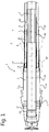
- FIG. 1 shows a cross section of an embodiment of a flue gas outlet assembly 1 according to the present invention.
- the flue gas outlet assembly 1 comprises a double wall tubular upper member 2 having an upper outer wall member 2a and an upper inner wall member 2b. Interposed between the upper outer wall member 2a and the upper inner wall member 2b is an upper cavity, an upper passageway or an upper duct for allowing a gas to pass there through.
- the upper cavity typically comprises an upper annular or annularly arranged duct 3.
- the flue gas outlet assembly 1 further comprises a double wall tubular lower member 4 having a lower outer wall member 4a and a lower inner wall member 4b. Interposed between the lower outer wall member 4a and the lower inner wall member 4b is a lower cavity, a lower passageway or a lower duct 5 for allowing a gas to pass through.
- the lower duct 5 typically comprises a lower annular or annularly arranged duct 3.
- the double wall tubular upper member 2 and the double wall tubular lower member 4 are arranged to connect the upper annular duct 3 to the lower annular duct 5, so that a continuous passageway is provided through the flue gas outlet assembly 1.
- the passageway defined by the upper and lower annular ducts 3, 5 is used as a gas intake, but it may also function as a gas outlet in specific applications.
- the upper inner wall member 2b may typically comprise an upper inner duct 6 extending there through connected to a lower inner duct 7 of the lower inner wall member 4b.
- the upper inner duct 6 and lower inner duct 7 provide a further continuous passageway through the flue gas outlet assembly 1, wherein the further passageway is typically used as a gas exhaust duct, but it may also function as a gas intake duct when necessary.
- the flue gas outlet assembly 1 of the present invention further comprises a locking member 10 in cooperative engagement with the double wall tubular upper member 2 and double wall tubular lower member 4.
- the locking member 10 of the present invention is arranged to allow for relative or mutual movement between the double wall tubular upper member 2 and double wall tubular lower member 4 in a longitudinal direction over a predetermined length.
- the locking member 10 is further arranged to interlock the double wall tubular upper member 2 and double wall tubular lower member 4 by a relative rotational movement there between over a predetermined angle.
- the locking member 10 is arranged for interlocking the double wall tubular upper member 2 and double wall tubular lower member 4 in a longitudinal direction of the flue gas outlet assembly 1, thereby fixing a desired extension length of the flue gas outlet assembly 1.
- the flue gas outlet assembly 1 of the present invention is advantageous as it can be shortened for packaging and transportation purposes and easily lengthened in one single movement when it is to be installed. Lengthening the flue gas outlet assembly 1 is readily accomplished by e.g. pulling the double wall tubular upper member 2 and double wall tubular lower member 4 apart in longitudinal fashion. Once a desired length of the flue gas assembly 1 has been reached, a relative rotational movement over a predetermined angle interlocks the double wall tubular upper member 2 and double wall tubular lower member 4 in the longitudinal direction.
- the double wall tubular upper member 2 and double wall tubular lower member 4 are telescopically arranged and so the relative movement there between comprises telescopic movement when the flue gas outlet assembly 1 is lengthened or shortened by respectively pulling or pushing the double wall tubular upper member 2 and double wall tubular lower member 4.
- the double wall tubular lower member 4 is longitudinally moveable or telescopically arranged within the upper annular duct 3.
- the telescopic range of movement between the double wall tubular upper member 2 and double wall tubular lower member 4 comprises 20 cm to 40 cm extension and retraction.
- longer telescopic ranges are possible, such as up to 150 cm extension or retraction if necessary, so that various onsite installation requirements can be met.
- the retracted length of the flue gas outlet assembly may be 100 cm or less, thereby providing a small transportation footprint and allowing for a larger number of flue gas outlet assemblies 1 to fit on a single transportation pallet.
- the double wall tubular lower member 4 may comprise a first spacer element 4d in a radial arrangement connecting the lower outer wall member 4a and lower inner wall member 4b.
- the first spaced element 4d may also provide an abutment face for the double wall tubular upper member 2 for defining a shortest possible retracted length of the flue gas outlet assembly 1,wherein the shortest possible retracted length will depend on packaging requirement of the flue gas outlet assembly 1.
- the double wall tubular upper member 2 comprises a second spacer element 2c in a radial arrangement connecting the upper outer wall member 2a and upper inner wall member 2b.
- the second spacer element 2c also provides substantial concentricity between the upper outer wall member 2a and upper inner wall member 2b, so that telescopic movement between the double wall tubular upper member 2 and the double wall tubular lower member 4 is facilitated.
- the second spaced element 2c may provide an abutment face for the double wall tubular lower member 4 for defining a shortest possible retracted length of the flue gas outlet assembly 1, so that the second spacer element 2c is in engagement with a maximally retracted double wall tubular lower member 4.
- the double wall tubular upper member 2 may also comprise an end stop element 2d configured to prevent further telescopic shortening of the flue gas outlet assembly 1, as the end of lower inner member 4b will abut the end stop element 2d.
- the end stop element 2d may be provided on an end part of the upper inner member 2b.
- FIG. 2 shows a detailed cross section (II) of an embodiment of a locking member 10 according to the present invention.
- the locking member 10 comprises a plurality of radially extending members 12 provided in a lengthwise or longitudinal direction on one of the double wall tubular upper member 2 and the double wall tubular lower member 4.
- a further radially extending member 14 is provided on the other of the double wall tubular upper member 2 and double wall tubular lower member 4.
- the plurality of radially extending members 12 and further radially extending member 14 allow for a convenient en reliable cooperative interlocking engagement between the double wall tubular upper member 2 and the double wall tubular lower member 4, whereby, in a locking configuration, the double wall tubular upper member 2 and the double wall tubular lower member 4 are longitudinally or lengthwise immovably interconnected.
- the further radially extending member 14 and the plurality of radially extending members 12 are arranged to allow for a releasable clamping arrangement there between.
- the releasable clamping arrangement prevents spontaneous relative rotation between the double wall tubular upper member 2 and the double wall tubular lower member 4.
- the clamping arrangement can however be released by actively applying a counter rotation force, such as by hand, to rotate the double wall tubular upper member 2 relative to the double wall tubular lower member 4.
- the flue gas outlet assembly 1 can be extended from an interlocked retracted minimum length ( Lmin ) to an interlocked extended maximum length ( Lmax ) or vice versa, wherein the further radially extending member 14 and the plurality of radially extending members 12 are arranged to allow for intermediate lengthening or retraction of the flue gas outlet assembly 1 between the interlocked minimum length ( Lmin ) and interlocked maximum length ( Lmax ).
- the difference between the interlocked minimum and interlocked maximum length ( Lmin, Lmax ) is the depicted interlocking adjustable length ( L1), i.e. the length of the plurality of radially extending members 12 along which the double wall tubular upper member 2 and the double wall tubular lower member 4 can be interlocked.
- the plurality of radially extending members 12 have a predetermined relative pitch distance ( dp ) .
- the pitch distance may be construed as the distance between two consecutive or adjacent radially extending members 12, so that the flue gas outlet assembly 1 can be lengthened or retracted with increments equal to the pitch distance ( dp ). Smaller pitch distances allow for finer length adjustments of the flue gas outlet assembly 1 than larger pitch distances.
- the plurality of radially extending members 12 may comprise a plurality of outwardly protruding members 12, and the further radially extending member 14 may comprise an inwardly protruding member 14.
- the plurality of radially extending member comprises a plurality of inwardly protruding member 12, and the further radially extending member 14 then comprises an outwardly protruding member 14.
- FIG. 3 shows a cross section of a further aspect of the present invention embodiments relating to the features of a locking member 10.
- each of the plurality of radially extending members 12 comprises a first ridge shaped element 12a circumferentially disposed over a predetermined first arc length a1.
- two circumferentially disposed ridge shaped elements 12a can be positioned on both sides of the further radially extending member 14 through a rotational movement, see Figure 2 for example, thereby interlocking the double wall tubular upper member 2 and the double wall tubular lower member 4 in a longitudinal or lengthwise fashion.
- the first arc length a1 determines at least in part an angular range of rotational movement in which the two ridge shaped elements 12a contribute to longitudinally interlocking the double wall tubular upper member 2 and the double wall tubular lower member 4.
- the further radially extending member 14 may also comprise a second ridge shaped element 14a circumferentially disposed over a predetermined second arc length a2, wherein the second arc length a2 also determines at least in part an angular range of rotational movement in which interlocking occurs between the double wall tubular upper member 2 and double wall tubular lower member 4.
- first ridge shaped element 12a comprises an elongated rectangular ridge shaped element or protrusion having a rectangular cross section and width w1 as shown in Figure 2 .
- second ridge shaped element 14a may also comprise an elongated rectangular ridge shaped element or protrusion having a rectangular cross section and width w2 as shown in Figure 2 .
- a reliable interlocked arrangement of the double wall tubular upper member 2 and the double wall tubular lower member 4 may be achieved through a releasable clamping arrangement there between.
- a clamping arrangement may be obtained by choosing the width w2 of the further radially extending member 14 somewhat larger than a gap between two adjacent first ridge shaped elements 12a.
- the width w2 may vary over the circumferential direction, e.g. with a linear increase, allowing proper alignment in a first part of the rotational movement, and a locking in a second part of the rotational movement.
- first and second ridge shaped element 12a, 14a may each comprise a rectangular cross section as depicted in Figure 2 . This ensures a congruent, reliable engagement there between when the double wall tubular upper member 2 and the double wall tubular lower member 4 are interlocked.
- first and second ridge shaped element 12a, 14a may each comprise a triangular, trapezoid, or semi circular cross section.
- the cross section of a first ridge shape element 12a may be different from the second ridge shaped element 14a.
- the flue gas outlet assembly 1 in particular the locking member 10, may comprise multiple groups of the plurality of radially extending members 12 and further radially extending member 14 provided in a circumferential direction, wherein said groups may in advantageous embodiments be regularly distributed in circumferential direction of the flue gas outlet assembly 1.
- each group comprising a plurality of radially extending members 12 and a further radially extending member 14, wherein the plurality of radially extending members 12 of each group, as well as the further radially extending member 14 of each group are evenly distributed in circumferential direction.
- first ridge shaped elements 12a separated by a first pitch angle ⁇ p1 of substantially 180° degrees
- second ridge shaped elements 14a separated by a second pitch angle ⁇ p2 of substantially 180° degrees
- the pitch angle may be viewed as an angle over which a regular circumferential pattern is obtained for two or more groups of the plurality of radially extending members 12 and the further radially extending member 14.
- the first and second arc length a1 , a2 may be chosen so as to obtain a desired predetermined angle ⁇ L over which a relative rotational movement is (maximally) required for interlocking to occur between the double wall tubular upper member 2 and the double wall tubular lower member 4.
- Rotational movement may be clockwise or counter clockwise.
- the first and second arc length a1 , a2 may be chosen so as to leave sufficient room in circumferential sense between the plurality of radially extending members 12 and the further radial extending member 14 for lengthwise or longitudinally moving the plurality of radially extending members 12 with respect to the further radially extending member 14, i.e. for relative telescopic movement between the double wall tubular upper member 2 and the double wall tubular lower member 4.
- two outwardly protruding members 12 and two inwardly protruding members 14 are evenly spaced in circumferential sense.
- the first and second arc length a1 , a2 are chosen such that the rotation angle ⁇ L is required, at most, for interlocking the double wall tubular upper member 2 and the double wall tubular lower member 4.
- a clockwise or counter clockwise rotation over the rotation angle ⁇ L or more will then interlock the double wall tubular upper member 2 and the double wall tubular lower member 4 in the longitudinal direction.
- the rotation angle ⁇ L of between 10° and 45° is in many application sufficient for providing the interlocked arrangement between the double wall tubular upper member 2 and the double wall tubular lower member 4.
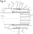
- Figure 4 shows a cross section of an embodiment of a sleeved end stop part 16 according to the present invention.
- the further radially extending member 14 is provided on an end part 16 of the upper outer wall member 2a. Positioning the further radially extending member 14 on the end part 16 maximises the possible extension length of the flue gas outlet assembly 1.
- the upper or lower outer wall member 2a, 4a may comprise a sleeved end stop part 4c arranged for defining a maximum extendible length for the flue gas outlet assembly 1.
- the sleeved end stop part 4c is arranged to abut against the further radially extending member 14 when the flue gas outlet assembly 1 is maximally extended, thereby preventing accidental separation of the double wall tubular upper member 2 and the double wall tubular lower member 4.
- the flue gas outlet assembly 1 may further comprise a sealing element 18 in sealing engagement with the double wall tubular upper member 2 and the double wall tubular lower member 4.
- the sealing element 18 may be disposed between the double wall tubular upper member 2 and the double wall tubular lower member 4 for preventing any gas leakage there between.
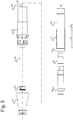
- FIG. 5 shows an exploded view of an embodiment of a flue gas outlet assembly according to the present invention.
- This embodiment exemplifies the mutual assembly of the upper outer and upper inner members 2a, 2b and the lower outer and lower inner members 4a, 4b.
- the interlocked adjustable length (L1) defined by the plurality of radially extending members 12 is augmented with an non-interlocking adjustable length L2 over which the flue gas assembly 1 can be retracted but cannot be interlocked.
- the non-interlocking adjustable length L2 may further reduce the retractable length to meet smaller packaging requirements of the flue gas outlet assembly 1.
- the non-interlocking adjustable length L2 may by a particular placement of the second spacer element as shown in Figure 1 or the end stop element 2d of the double wall tubular upper member 2, in particular the upper inner member 2b. Further, in the embodiment shown the end part of the upper outer member 2a comprises the further radially extending member 14.
- an inner nominal diameter D i of the lower inner wall member 4b is between 60 mm and 90 mm, and an outer nominal diameter D o of the lower outer wall member 4a is between 100 mm and 150 mm.
- an inner nominal diameter D i of the lower inner wall member 4b is between 60 mm and 100 mm, and an outer nominal diameter D o of the lower outer wall member 4a is between 100 mm and 150 mm.
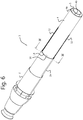
- FIG. 6 shows a three dimensional view of an embodiment of a flue gas outlet assembly 1 according to the present invention.
- the flue gas outlet assembly 1 comprises two groups of the plurality of radially extending members 12, wherein the double wall tubular lower member 4 comprises two groups of longitudinally arranged radially extending members 12 separated over 180° degrees in circumferential sense.
- the end part 16 of the upper outer member 2a comprises the further radially extending member 14, which is in interlocked engagement with one of more radially extending members 12.
- the double wall tubular lower member 4 is telescopically and moveably arranged within the upper annular duct 3 (not shown) of the double wall tubular upper member 2.
- the flue gas outlet assembly 1 can be manually adjusted by rotating the double wall tubular lower member 4 with respect to the double wall tubular upper member 2. Once the plurality of radially extending members 12 are cleared from the further radially extending member 14 through the rotational movement over the predetermined angle, i.e. the rotation angle ⁇ L , the double wall tubular upper member 2 and double wall tubular lower member 4 are telescopically movable, thus retraceable or extendible.
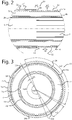
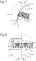
- Figure 7 and 8 each show a further embodiment of the plurality of radially extending members 12 and the further extending member 14.
- Figure 7 shows a three dimensional view
- Figure 8 depicts a top view of an embodiment of a releasable clamping arrangement according to the present invention.
- the further radially extending member 14 (e.g. the second ridge shaped element 14a) may be arranged for being wedged between two successive or adjacent radially extending members 12 (e.g. the first ridge shaped elements 12a) for interlocking the double wall tubular upper member 2 and the double wall tubular lower member 4.
- each of the plurality of radially extending members 12 may comprise a triangular profile 12b in circumferential direction. Consequently, the two consecutive or adjacent radially extending members 12 define a funnel shaped gap there between having a base width w3 which is larger than a top width w4 of the funnel shaped gap.
- the further radially extending member 14 may be provided with a bead shaped locking tip 17 congruently receivable into a locking pocket 13 defined by two adjacent radially extending members 12, such as two adjacent first ridge shaped elements 12a.
- the pitch distance dp may be viewed as the distance between two adjacent or consecutive locking pockets 13 defining the smallest possible interlocking adjustable length of the flue gas outlet assembly 1.
- the two adjacent radially extending members 12 may have sufficient resiliency or flexibility to allow for the further radially extending member 14 to be wedged there between with adequate clamping force.
- the locking tip 17 may have a width larger than the top width w4, so that once the locking tip 17 passes through the top width w4 into the locking pocket 13, the locking tip 17 is firmly interlocked and relative rotation between the double wall tubular upper member 2 and the double wall tubular lower member 4 is thereby prevented. Imposing an opposite relative rotation releases the locking tip 17 from the locking pocket 13, so that the flue gas outlet assembly 1 is adjustable in length once again.
- the lower outer wall 4a has an outer diameter slightly smaller or equal to an inner diameter of the upper outer wall 2a, allowing the lower member 4 to slide in the upper member 2.
- the lower inner wall 4b has an inner diameter slightly smaller than or equal to an outer diameter of the upper inner wall 2b.
- this can be reversed in further embodiments, as such or in combination with the selection of outer wall 2a, 4b diameters.
- the position and direction of various components as described above can be suitably adapted, such as the plurality of radially extending member 12 and further radially extending member 14 of the locking member 10, and the sealing element 18.
Landscapes
- Engineering & Computer Science (AREA)
- Mechanical Engineering (AREA)
- General Engineering & Computer Science (AREA)
- Chemical & Material Sciences (AREA)
- Combustion & Propulsion (AREA)
- Incineration Of Waste (AREA)
Claims (15)
- Rauchgasauslassanordnung (1) zum Zuführen und/oder Abführen von Gasen aufweisend ein doppelwandiges rohrförmiges oberes Element (2) mit einem oberen Außenwandelement (2a), einem oberen Innenwandelement (2b) und einem oberen ringförmigen Kanal (3), der dazwischen angeordnet ist,
ein doppelwandiges rohrförmiges unteres Element (4) mit einem unteren Außenwandelement (4a), einem unteren Innenwandelement (4b) und einem unteren ringförmigen Kanal (5), der dazwischen angeordnet ist,
wobei das doppelwandige rohrförmige obere Element (2) und das doppelwandige rohrförmige untere Element (4) derart angeordnet sind, dass sie den oberen ringförmigen Kanal (3) mit dem unteren ringförmigen Kanal (5) verbinden, wobei die Rauchgasauslassanordnung (1) ferner umfasst
ein Verriegelungselement (10) in zusammenwirkendem Eingriff mit dem doppelwandigen rohrförmigen oberen Element (2) und dem doppelwandigen rohrförmigen unteren Element (4), wobei das Verriegelungselement (10) derart angeordnet ist, dass es eine Relativbewegung zwischen dem doppelwandigen rohrförmigen oberen Element (2) und dem doppelwandigen rohrförmigen unteren Element (4) in einer Längsrichtung über eine vorbestimmte Länge ermöglicht und das doppelwandige rohrförmige obere Element (2) und das doppelwandige rohrförmige untere Element (4) durch eine relative Drehbewegung zwischen diesen über einen vorbestimmten Winkel miteinander verriegelt. - Rauchgasauslassanordnung nach Anspruch 1, bei der das Verriegelungselement (10) eine Vielzahl von sich radial erstreckenden Elementen (12), die in einer Längsrichtung an einem des doppelwandigen rohrförmigen oberen Elements (2) und des doppelwandigen rohrförmigen unteren Elements (4) vorgesehen sind, und ein weiteres sich radial erstreckendes Element (14), das an dem anderen des doppelwandigen rohrförmigen oberen Elements (2) und des doppelwandigen rohrförmigen unteren Elements (4) vorgesehen ist, umfasst.
- Rauchgasauslassanordnung nach Anspruch 2, bei der das weitere sich radial erstreckende Element (14) und die Vielzahl von sich radial erstreckenden Elementen (12) derart angeordnet sind, dass sie eine lösbare Klemmanordnung zwischen ihnen ermöglichen.
- Rauchgasauslassanordnung nach Anspruch 2 oder 3, bei der jedes der sich radial erstreckenden Elemente (12) ein erstes rippenförmiges Element (12a) umfasst, das über eine vorbestimmte erste Bogenlänge (a1) am Umfang angeordnet ist.
- Rauchgasauslassanordnung nach einem der Ansprüche 2 bis 4, bei der die Vielzahl von sich radial erstreckenden Elementen (12) einen vorbestimmten Teilungsabstand (dp ) aufweisen.
- Rauchgasauslassanordnung nach einem der Ansprüche 2 bis 5, bei der das weitere sich radial erstreckende Element (14) ein zweites rippenförmiges Element (14a) aufweist, das über eine vorbestimmte zweite Bogenlänge (a2) am Umfang angeordnet ist.
- Rauchgasauslassanordnung nach einem der Ansprüche 2 bis 6, bei der mehrere Gruppen der Vielzahl von sich radial erstreckenden Elementen (12) und das weitere sich radial erstreckende Element (14) in einer Umfangsrichtung vorgesehen sind.
- Rauchgasauslassanordnung nach einem der Ansprüche 2 bis 7, bei der das weitere sich radial erstreckende Element (14) an einem Endteil (16) des oberen Außenwandelements (2a) vorgesehen ist.
- Rauchgasauslassanordnung nach einem der Ansprüche 2 bis 8, bei der die Vielzahl von sich radial erstreckenden Elementen (12) und das weitere sich radial erstreckende Element (14) über einen Drehwinkel (αL) zwischen 10° und 45° miteinander verriegelt sind.
- Rauchgasauslassanordnung nach einem der Ansprüche 1 bis 9, bei der das obere oder das untere Außenwandelement (2a, 4a) einen hülsenartigen Endanschlagteil (4c) umfasst, der zum Definieren einer maximalen Erstreckungsläge für die Rauchgasauslassanordnung (1) angeordnet ist.
- Rauchgasauslassanordnung nach einem der Ansprüche 1 bis 10, bei der das doppelwandige rohrförmige untere Element (4) ein erstes Abstandshalterelement (4d) in einer radialen Anordnung umfasst, das das untere Außenwandelement (4a) und das untere Innenwandelement (4b) verbindet.
- Rauchgasauslassanordnung nach einem der Ansprüche 1 bis 11, bei der das doppelwandige rohrförmige obere Element (2) ein zweites Abstandshalterelement (2c) in einer radialen Anordnung umfasst, das das obere Außenwandelement (2a) und das obere Innenwandelement (2b) verbindet.
- Rauchgasauslassanordnung nach Anspruch 12, bei der das zweite Abstandshalterelement (2c) in Eingriff mit einem maximal zurückgezogenen doppelwandigen rohrförmigen unteren Element (4) steht.
- Rauchgasauslassanordnung nach einem der Ansprüche 1 bis 13, die ferner ein Dichtungselement (18) in dichtendem Eingriff mit dem doppelwandigen rohrförmigen oberen Element (2) und dem doppelwandigen rohrförmigen unteren Element (4) umfasst.
- Rauchgasauslassanordnung nach einem der Ansprüche 1 bis 14, bei der ein Innennenndurchmesser (Di) des unteren Innenwandelelements (4b) zwischen 60 mm und 100 mm liegt und ein Außennenndurchmesser (Do) des unteren Außenwandelements (4a) zwischen 100 mm und 150 mm liegt.
Applications Claiming Priority (1)
| Application Number | Priority Date | Filing Date | Title |
|---|---|---|---|
| NL2013673A NL2013673B1 (en) | 2014-10-23 | 2014-10-23 | Flue gas outlet assembly. |
Publications (2)
| Publication Number | Publication Date |
|---|---|
| EP3012528A1 EP3012528A1 (de) | 2016-04-27 |
| EP3012528B1 true EP3012528B1 (de) | 2018-09-26 |
Family
ID=52472490
Family Applications (1)
| Application Number | Title | Priority Date | Filing Date |
|---|---|---|---|
| EP15190740.9A Active EP3012528B1 (de) | 2014-10-23 | 2015-10-21 | Rauchgasauslassanordnung |
Country Status (2)
| Country | Link |
|---|---|
| EP (1) | EP3012528B1 (de) |
| NL (1) | NL2013673B1 (de) |
Families Citing this family (1)
| Publication number | Priority date | Publication date | Assignee | Title |
|---|---|---|---|---|
| NL2032741B1 (en) | 2022-08-12 | 2024-02-16 | M & G Group Europe B V | Roof terminal adapter |
Family Cites Families (4)
| Publication number | Priority date | Publication date | Assignee | Title |
|---|---|---|---|---|
| US2910308A (en) * | 1956-04-10 | 1959-10-27 | Dura Vent Corp | Snap-in lug-in-groove type resilient conduit joint |
| US3066959A (en) * | 1958-12-29 | 1962-12-04 | White Harry | Vent pipes concurrently locked against axial and rotational displacement |
| FR2298062A1 (fr) * | 1975-01-17 | 1976-08-13 | Leblanc Sa E L M | Ventouse pour appareil de production d'eau chaude ou de chauffage |
| JPS51145064A (en) | 1975-06-09 | 1976-12-13 | Tetsuaki Koga | Method of purification of a dust- containing gas and its enforcement d evice |
-
2014
- 2014-10-23 NL NL2013673A patent/NL2013673B1/en not_active IP Right Cessation
-
2015
- 2015-10-21 EP EP15190740.9A patent/EP3012528B1/de active Active
Non-Patent Citations (1)
| Title |
|---|
| None * |
Also Published As
| Publication number | Publication date |
|---|---|
| EP3012528A1 (de) | 2016-04-27 |
| NL2013673B1 (en) | 2016-10-06 |
Similar Documents
| Publication | Publication Date | Title |
|---|---|---|
| EP2492518A1 (de) | Mastanordnung | |
| US20100005735A1 (en) | Telescoping shoring post with gross adjustment capacity | |
| KR101670111B1 (ko) | 지지 슬리브를 구비한 푸쉬-피트 파이프 피팅 시스템 | |
| CA2454070A1 (en) | Expander for expanding a tubular element | |
| SE463115B (sv) | Instickskoppling foer foerbindning av aendarna paa tvaa roer | |
| FI76876B (fi) | Ledroer av plast, saerskilt foer avfallsvatten. | |
| EP2937631B1 (de) | Gas-Heißluftpistolenkopf | |
| SE465838B (sv) | Roerkoppling | |
| JP2014163664A5 (de) | ||
| JP2015129514A5 (de) | ||
| NL2013673B1 (en) | Flue gas outlet assembly. | |
| EP2059707B1 (de) | Anordnung zur verbindung von röhrenelementen in einem belüftungskanalsystem | |
| WO2016083879A1 (en) | Flux-cored brazing preform | |
| US10221979B2 (en) | Detachable tube coupling system | |
| EP0643250B1 (de) | Doppelwandiges Rohrleitungssystem | |
| ITUD940195A1 (it) | Combinazione di un tubo flessibile per aria e di un bocchettone di allacciamento e bocchettone di allacciamento per detta | |
| CN108825913B (zh) | 一种长度和角度双调节型风管弯头 | |
| EP2982816B1 (de) | Telescopstangen | |
| EP3101355B1 (de) | Entlüftungsöffnung | |
| US11092270B2 (en) | Elbow-equipped expansion joint | |
| JP2019517643A5 (de) | ||
| JP2019183983A (ja) | 波付管の接続体及び拡開防止具 | |
| US20120086198A1 (en) | Connecting device for two pipes overlapping in sections | |
| US8770883B1 (en) | Pivot connector for modular platform assemblies | |
| CN108758143B (zh) | 一种活接调节式风管弯头 |
Legal Events
| Date | Code | Title | Description |
|---|---|---|---|
| PUAI | Public reference made under article 153(3) epc to a published international application that has entered the european phase |
Free format text: ORIGINAL CODE: 0009012 |
|
| AK | Designated contracting states |
Kind code of ref document: A1 Designated state(s): AL AT BE BG CH CY CZ DE DK EE ES FI FR GB GR HR HU IE IS IT LI LT LU LV MC MK MT NL NO PL PT RO RS SE SI SK SM TR |
|
| AX | Request for extension of the european patent |
Extension state: BA ME |
|
| 17P | Request for examination filed |
Effective date: 20161013 |
|
| RBV | Designated contracting states (corrected) |
Designated state(s): AL AT BE BG CH CY CZ DE DK EE ES FI FR GB GR HR HU IE IS IT LI LT LU LV MC MK MT NL NO PL PT RO RS SE SI SK SM TR |
|
| 17Q | First examination report despatched |
Effective date: 20170817 |
|
| RAP1 | Party data changed (applicant data changed or rights of an application transferred) |
Owner name: M & G GROUP EUROPE B.V. |
|
| GRAP | Despatch of communication of intention to grant a patent |
Free format text: ORIGINAL CODE: EPIDOSNIGR1 |
|
| INTG | Intention to grant announced |
Effective date: 20180516 |
|
| GRAS | Grant fee paid |
Free format text: ORIGINAL CODE: EPIDOSNIGR3 |
|
| GRAA | (expected) grant |
Free format text: ORIGINAL CODE: 0009210 |
|
| AK | Designated contracting states |
Kind code of ref document: B1 Designated state(s): AL AT BE BG CH CY CZ DE DK EE ES FI FR GB GR HR HU IE IS IT LI LT LU LV MC MK MT NL NO PL PT RO RS SE SI SK SM TR |
|
| REG | Reference to a national code |
Ref country code: GB Ref legal event code: FG4D |
|
| REG | Reference to a national code |
Ref country code: CH Ref legal event code: EP |
|
| REG | Reference to a national code |
Ref country code: AT Ref legal event code: REF Ref document number: 1046458 Country of ref document: AT Kind code of ref document: T Effective date: 20181015 |
|
| REG | Reference to a national code |
Ref country code: IE Ref legal event code: FG4D |
|
| REG | Reference to a national code |
Ref country code: DE Ref legal event code: R096 Ref document number: 602015016861 Country of ref document: DE |
|
| REG | Reference to a national code |
Ref country code: FR Ref legal event code: PLFP Year of fee payment: 4 |
|
| REG | Reference to a national code |
Ref country code: NL Ref legal event code: FP |
|
| PG25 | Lapsed in a contracting state [announced via postgrant information from national office to epo] |
Ref country code: GR Free format text: LAPSE BECAUSE OF FAILURE TO SUBMIT A TRANSLATION OF THE DESCRIPTION OR TO PAY THE FEE WITHIN THE PRESCRIBED TIME-LIMIT Effective date: 20181227 Ref country code: BG Free format text: LAPSE BECAUSE OF FAILURE TO SUBMIT A TRANSLATION OF THE DESCRIPTION OR TO PAY THE FEE WITHIN THE PRESCRIBED TIME-LIMIT Effective date: 20181226 Ref country code: NO Free format text: LAPSE BECAUSE OF FAILURE TO SUBMIT A TRANSLATION OF THE DESCRIPTION OR TO PAY THE FEE WITHIN THE PRESCRIBED TIME-LIMIT Effective date: 20181226 Ref country code: RS Free format text: LAPSE BECAUSE OF FAILURE TO SUBMIT A TRANSLATION OF THE DESCRIPTION OR TO PAY THE FEE WITHIN THE PRESCRIBED TIME-LIMIT Effective date: 20180926 Ref country code: FI Free format text: LAPSE BECAUSE OF FAILURE TO SUBMIT A TRANSLATION OF THE DESCRIPTION OR TO PAY THE FEE WITHIN THE PRESCRIBED TIME-LIMIT Effective date: 20180926 Ref country code: LT Free format text: LAPSE BECAUSE OF FAILURE TO SUBMIT A TRANSLATION OF THE DESCRIPTION OR TO PAY THE FEE WITHIN THE PRESCRIBED TIME-LIMIT Effective date: 20180926 Ref country code: SE Free format text: LAPSE BECAUSE OF FAILURE TO SUBMIT A TRANSLATION OF THE DESCRIPTION OR TO PAY THE FEE WITHIN THE PRESCRIBED TIME-LIMIT Effective date: 20180926 |
|
| REG | Reference to a national code |
Ref country code: LT Ref legal event code: MG4D |
|
| PG25 | Lapsed in a contracting state [announced via postgrant information from national office to epo] |
Ref country code: AL Free format text: LAPSE BECAUSE OF FAILURE TO SUBMIT A TRANSLATION OF THE DESCRIPTION OR TO PAY THE FEE WITHIN THE PRESCRIBED TIME-LIMIT Effective date: 20180926 Ref country code: HR Free format text: LAPSE BECAUSE OF FAILURE TO SUBMIT A TRANSLATION OF THE DESCRIPTION OR TO PAY THE FEE WITHIN THE PRESCRIBED TIME-LIMIT Effective date: 20180926 Ref country code: LV Free format text: LAPSE BECAUSE OF FAILURE TO SUBMIT A TRANSLATION OF THE DESCRIPTION OR TO PAY THE FEE WITHIN THE PRESCRIBED TIME-LIMIT Effective date: 20180926 |
|
| REG | Reference to a national code |
Ref country code: AT Ref legal event code: MK05 Ref document number: 1046458 Country of ref document: AT Kind code of ref document: T Effective date: 20180926 |
|
| PG25 | Lapsed in a contracting state [announced via postgrant information from national office to epo] |
Ref country code: AT Free format text: LAPSE BECAUSE OF FAILURE TO SUBMIT A TRANSLATION OF THE DESCRIPTION OR TO PAY THE FEE WITHIN THE PRESCRIBED TIME-LIMIT Effective date: 20180926 Ref country code: PL Free format text: LAPSE BECAUSE OF FAILURE TO SUBMIT A TRANSLATION OF THE DESCRIPTION OR TO PAY THE FEE WITHIN THE PRESCRIBED TIME-LIMIT Effective date: 20180926 Ref country code: EE Free format text: LAPSE BECAUSE OF FAILURE TO SUBMIT A TRANSLATION OF THE DESCRIPTION OR TO PAY THE FEE WITHIN THE PRESCRIBED TIME-LIMIT Effective date: 20180926 Ref country code: IS Free format text: LAPSE BECAUSE OF FAILURE TO SUBMIT A TRANSLATION OF THE DESCRIPTION OR TO PAY THE FEE WITHIN THE PRESCRIBED TIME-LIMIT Effective date: 20190126 Ref country code: CZ Free format text: LAPSE BECAUSE OF FAILURE TO SUBMIT A TRANSLATION OF THE DESCRIPTION OR TO PAY THE FEE WITHIN THE PRESCRIBED TIME-LIMIT Effective date: 20180926 Ref country code: ES Free format text: LAPSE BECAUSE OF FAILURE TO SUBMIT A TRANSLATION OF THE DESCRIPTION OR TO PAY THE FEE WITHIN THE PRESCRIBED TIME-LIMIT Effective date: 20180926 Ref country code: RO Free format text: LAPSE BECAUSE OF FAILURE TO SUBMIT A TRANSLATION OF THE DESCRIPTION OR TO PAY THE FEE WITHIN THE PRESCRIBED TIME-LIMIT Effective date: 20180926 |
|
| PG25 | Lapsed in a contracting state [announced via postgrant information from national office to epo] |
Ref country code: PT Free format text: LAPSE BECAUSE OF FAILURE TO SUBMIT A TRANSLATION OF THE DESCRIPTION OR TO PAY THE FEE WITHIN THE PRESCRIBED TIME-LIMIT Effective date: 20190126 Ref country code: SM Free format text: LAPSE BECAUSE OF FAILURE TO SUBMIT A TRANSLATION OF THE DESCRIPTION OR TO PAY THE FEE WITHIN THE PRESCRIBED TIME-LIMIT Effective date: 20180926 Ref country code: SK Free format text: LAPSE BECAUSE OF FAILURE TO SUBMIT A TRANSLATION OF THE DESCRIPTION OR TO PAY THE FEE WITHIN THE PRESCRIBED TIME-LIMIT Effective date: 20180926 |
|
| REG | Reference to a national code |
Ref country code: CH Ref legal event code: PL |
|
| REG | Reference to a national code |
Ref country code: DE Ref legal event code: R097 Ref document number: 602015016861 Country of ref document: DE |
|
| PG25 | Lapsed in a contracting state [announced via postgrant information from national office to epo] |
Ref country code: LU Free format text: LAPSE BECAUSE OF NON-PAYMENT OF DUE FEES Effective date: 20181021 |
|
| REG | Reference to a national code |
Ref country code: IE Ref legal event code: MM4A |
|
| PG25 | Lapsed in a contracting state [announced via postgrant information from national office to epo] |
Ref country code: DK Free format text: LAPSE BECAUSE OF FAILURE TO SUBMIT A TRANSLATION OF THE DESCRIPTION OR TO PAY THE FEE WITHIN THE PRESCRIBED TIME-LIMIT Effective date: 20180926 Ref country code: MC Free format text: LAPSE BECAUSE OF FAILURE TO SUBMIT A TRANSLATION OF THE DESCRIPTION OR TO PAY THE FEE WITHIN THE PRESCRIBED TIME-LIMIT Effective date: 20180926 |
|
| PLBE | No opposition filed within time limit |
Free format text: ORIGINAL CODE: 0009261 |
|
| STAA | Information on the status of an ep patent application or granted ep patent |
Free format text: STATUS: NO OPPOSITION FILED WITHIN TIME LIMIT |
|
| PG25 | Lapsed in a contracting state [announced via postgrant information from national office to epo] |
Ref country code: CH Free format text: LAPSE BECAUSE OF NON-PAYMENT OF DUE FEES Effective date: 20181031 Ref country code: LI Free format text: LAPSE BECAUSE OF NON-PAYMENT OF DUE FEES Effective date: 20181031 |
|
| 26N | No opposition filed |
Effective date: 20190627 |
|
| PG25 | Lapsed in a contracting state [announced via postgrant information from national office to epo] |
Ref country code: SI Free format text: LAPSE BECAUSE OF FAILURE TO SUBMIT A TRANSLATION OF THE DESCRIPTION OR TO PAY THE FEE WITHIN THE PRESCRIBED TIME-LIMIT Effective date: 20180926 Ref country code: IE Free format text: LAPSE BECAUSE OF NON-PAYMENT OF DUE FEES Effective date: 20181021 |
|
| PG25 | Lapsed in a contracting state [announced via postgrant information from national office to epo] |
Ref country code: MT Free format text: LAPSE BECAUSE OF NON-PAYMENT OF DUE FEES Effective date: 20181021 |
|
| PG25 | Lapsed in a contracting state [announced via postgrant information from national office to epo] |
Ref country code: TR Free format text: LAPSE BECAUSE OF FAILURE TO SUBMIT A TRANSLATION OF THE DESCRIPTION OR TO PAY THE FEE WITHIN THE PRESCRIBED TIME-LIMIT Effective date: 20180926 |
|
| PG25 | Lapsed in a contracting state [announced via postgrant information from national office to epo] |
Ref country code: CY Free format text: LAPSE BECAUSE OF FAILURE TO SUBMIT A TRANSLATION OF THE DESCRIPTION OR TO PAY THE FEE WITHIN THE PRESCRIBED TIME-LIMIT Effective date: 20180926 Ref country code: MK Free format text: LAPSE BECAUSE OF NON-PAYMENT OF DUE FEES Effective date: 20180926 Ref country code: HU Free format text: LAPSE BECAUSE OF FAILURE TO SUBMIT A TRANSLATION OF THE DESCRIPTION OR TO PAY THE FEE WITHIN THE PRESCRIBED TIME-LIMIT; INVALID AB INITIO Effective date: 20151021 |
|
| P01 | Opt-out of the competence of the unified patent court (upc) registered |
Effective date: 20230518 |
|
| PGFP | Annual fee paid to national office [announced via postgrant information from national office to epo] |
Ref country code: NL Payment date: 20250925 Year of fee payment: 11 |
|
| PGFP | Annual fee paid to national office [announced via postgrant information from national office to epo] |
Ref country code: DE Payment date: 20251028 Year of fee payment: 11 |
|
| PGFP | Annual fee paid to national office [announced via postgrant information from national office to epo] |
Ref country code: GB Payment date: 20251023 Year of fee payment: 11 |
|
| PGFP | Annual fee paid to national office [announced via postgrant information from national office to epo] |
Ref country code: IT Payment date: 20251022 Year of fee payment: 11 |
|
| PGFP | Annual fee paid to national office [announced via postgrant information from national office to epo] |
Ref country code: FR Payment date: 20251027 Year of fee payment: 11 |
|
| PGFP | Annual fee paid to national office [announced via postgrant information from national office to epo] |
Ref country code: BE Payment date: 20251024 Year of fee payment: 11 |