EP3012470A1 - Écrou de fixation sur une tôle - Google Patents
Écrou de fixation sur une tôle Download PDFInfo
- Publication number
- EP3012470A1 EP3012470A1 EP14190285.8A EP14190285A EP3012470A1 EP 3012470 A1 EP3012470 A1 EP 3012470A1 EP 14190285 A EP14190285 A EP 14190285A EP 3012470 A1 EP3012470 A1 EP 3012470A1
- Authority
- EP
- European Patent Office
- Prior art keywords
- nut
- sheet
- internal thread
- hole
- punching
- Prior art date
- Legal status (The legal status is an assumption and is not a legal conclusion. Google has not performed a legal analysis and makes no representation as to the accuracy of the status listed.)
- Granted
Links
- 239000002184 metal Substances 0.000 title claims abstract description 35
- 238000000034 method Methods 0.000 claims abstract description 13
- 239000000463 material Substances 0.000 claims abstract description 8
- 238000011144 upstream manufacturing Methods 0.000 claims abstract description 3
- 238000004080 punching Methods 0.000 claims description 23
- 238000003825 pressing Methods 0.000 claims description 13
- 238000006073 displacement reaction Methods 0.000 claims description 3
- 238000003780 insertion Methods 0.000 claims description 2
- 230000037431 insertion Effects 0.000 claims description 2
- 238000007599 discharging Methods 0.000 claims 1
- 238000011161 development Methods 0.000 description 6
- 230000018109 developmental process Effects 0.000 description 6
- 238000004049 embossing Methods 0.000 description 1
- 230000001747 exhibiting effect Effects 0.000 description 1
- 238000009434 installation Methods 0.000 description 1
- 238000012423 maintenance Methods 0.000 description 1
- 238000004519 manufacturing process Methods 0.000 description 1
- 239000011159 matrix material Substances 0.000 description 1
- 239000007769 metal material Substances 0.000 description 1
- 238000000465 moulding Methods 0.000 description 1
Images


Classifications
-
- F—MECHANICAL ENGINEERING; LIGHTING; HEATING; WEAPONS; BLASTING
- F16—ENGINEERING ELEMENTS AND UNITS; GENERAL MEASURES FOR PRODUCING AND MAINTAINING EFFECTIVE FUNCTIONING OF MACHINES OR INSTALLATIONS; THERMAL INSULATION IN GENERAL
- F16B—DEVICES FOR FASTENING OR SECURING CONSTRUCTIONAL ELEMENTS OR MACHINE PARTS TOGETHER, e.g. NAILS, BOLTS, CIRCLIPS, CLAMPS, CLIPS OR WEDGES; JOINTS OR JOINTING
- F16B37/00—Nuts or like thread-engaging members
- F16B37/04—Devices for fastening nuts to surfaces, e.g. sheets, plates
- F16B37/06—Devices for fastening nuts to surfaces, e.g. sheets, plates by means of welding or riveting
- F16B37/062—Devices for fastening nuts to surfaces, e.g. sheets, plates by means of welding or riveting by means of riveting
- F16B37/068—Devices for fastening nuts to surfaces, e.g. sheets, plates by means of welding or riveting by means of riveting by deforming the material of the support, e.g. the sheet or plate
Definitions
- the invention further relates to a tool for connecting such a nut with a metal sheet according to claim 9, a nut-sheet metal connection with such a nut according to the patent claim 13 and a method for fixing such a nut to a metal sheet according to claim 14.
- punching nuts are used, as they are among others from the DE 36 26 466 are known.
- Such a punch nut is pressed into a non-pre-punched sheet and acts as a punch, which punches a slug from the sheet.
- the counterforce is applied by a die, which supports the sheet metal on the side opposite the punching nut around the punched out around the neck.
- Punching nuts in which only the plate, but not the nut itself is deformed during the press-fitting process of the mother in the sheet, are to be distinguished from the similarly designed so-called rivet nuts, in which during the Einpressvorgangs and the mother, in part in addition to the sheet, usually in free end of the shaft portion is deformed.
- the invention aims to remedy this situation.
- the invention is based on the object to provide a nut for attachment to a metal sheet, in particular to a thin sheet metal sheet thickness of ⁇ 1.5 mm, which allows a time and effort minimized attachment to a metal sheet. According to the invention, this object is solved by the features of the characterizing part of patent claim 1.
- a nut is provided for attachment to a metal sheet, which allows a time and effort minimized attachment to the sheet.
- a sheet metal connection by molding of sheet material in the nut body is made possible.
- the connection of sheet metal and nut is achieved by the introduced in the manner of a collar in the mother body sheet material, which is pressed against the fastening contour.
- the nut body can have both a round and a polygonal cross-section.
- the nut body may also be provided at the end with a flange, whereby the contact surface is increased on the sheet.
- the sheet to be joined with the mother can also be designed as a multi-layer or sandwich sheet.
- the nut can also be used for the purpose of connecting two or more sheets.
- the fastening contour has a pressing section which merges into a passage section reduced in diameter relative to the pressing section.
- a shoulder is formed between the pressing portion and the outlet portion.
- the shoulder is preferably formed as a conically inclined annular surface in the direction of the outer shell of the nut body, whereby the strength of the connection between nut and plate is further improved.
- the outlet section and / or the pressing section are cylindrical. As a result, the production of the nut body is simplified.
- the fastening contour has a tapering in the direction of the internal thread centering, which adjoins the internal thread. This allows a good centering of the Umformungsstkovs relative to the mother.
- the outlet portion and / or the pressing portion is at least partially provided with a toothing.
- the nut body is provided on its side facing away from the internal thread contact surface with a toothing or ribbing.
- the invention is further based on the object to provide a tool for connecting such a nut with a metal sheet, which allows a time and effort minimized attachment of the nut to a metal sheet. According to the invention, this object is achieved by a tool having the features of claim 9.
- a tool for connecting an aforementioned mother is provided with a metal sheet that allows a time and effort minimized attachment of the nut to a metal sheet.
- the tool has a support hole having a first bore, in which a Durgangsbohrung exhibiting a forming die for insertion into the mounting contour of the nut body of the nut is slidably disposed.
- a punching and centering punch which can be moved into the through bore of the forming punch and whose outer diameter is essentially the same as that of FIG Core diameter of the internal thread of the nut corresponds.
- the attachment of the nut can be done via a single step, which includes a pre-perforation and sheet metal displacement or sheet metal embossing or sheet metal allocation in the fastening contour of the nut body.
- the punching and centering punch which can be moved into the through bore of the forming punch, the sheet can first be punched through the nut body. Subsequently, with the fate of the punching and centering punch in the nut, the sheet metal area surrounding the hole can be shaped into the fastening contour of the nut via the forming punch, which is movable along the punching and centering punch.
- the through-bore of the forming die has an enlarged diameter portion for removing a stamped by the punching and centering stamped from the sheet metal stamping. As a result, a hindrance of the subsequent forming process is avoided by the punched joint.
- the support block is mounted resiliently in the displacement direction relative to the forming die. This causes a movement of the tool in the initial state after the attachment of a nut to a plate by the restoring forces of a spring element.
- a shoulder is preferably integrally formed on the forming die, at least in regions, on which the support block can be tapped.
- connection between one of the aforementioned nuts and a sheet metal is preferably formed such that a hole is punched into the sheet, wherein a sheet metal surrounding the hole is formed in the manner of a collar in the fastening contour of the nut body of the nut and rests against this, whereby the Connection is effected.
- the invention is further based on the object to provide a method for fixing a nut of the aforementioned type to a sheet, which allows a time and effort minimized attachment of the nut to the sheet. According to the invention, this object is solved by the features of claim 15.
- a method for fixing a nut of the aforementioned type is provided on a metal sheet, by allowing a time and effort minimized attachment of the nut to the sheet.
- the perforation of the sheet is effected by a punching and centering punch, which is guided by the internal thread of the nut (more precisely, by the passage of the nut limited by the internal thread) and punches the hole in the sheet, wherein the punching and centering during the subsequent forming process in which the voltage applied to the mounting plate metal collar is formed within the internal thread of the nut remains.
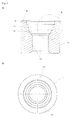
- the selected as an embodiment nut 1 consists essentially of a hollow cylindrical nut body 11 having an internal thread 12.
- the outer contour of the nut 1 corresponds to a common, known in the prior art contour for a positionally correct feed.
- the female thread 12 is adjoined by a fastening contour 13 formed by a countersink.
- the fastening contour 13 comprises a conically widening centering section 14, adjoined by a cylindrically formed outlet section 15, which merges into a likewise cylindrically shaped, diameter-expanded pressing section 16.
- a shoulder 17 is formed, which is formed inclined radially outwardly, so that a conically tapering inwardly annular surface is formed.
- the outlet section 15 is provided in the embodiment with a - not shown - ribbing.
- the depth of the counterbore and thus the fastening contour 13 is matched to the diameter of the internal thread 12.
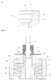
- FIG. 2 a tool for connecting the nut described above with a sheet 8.
- the tool 2 comprises a housing 3, in which a support block 4 is mounted via a spring 7.
- the support block 4 is penetrated by a forming die 5, in the through hole 55, a punching and centering 6 is hineinbewegbar.
- the housing 3 is formed substantially hollow cylindrical. At its upper side, the housing 3 is executed reduced in diameter, whereby a stop 31 is formed to bear the support bracket 4. At its end opposite the stop 31, a ring plate 32 is arranged in the housing 3. The ring plate 32 serves both the support of a spring 7 and the system of the forming die 5, from which it is penetrated.
- the support block 4 is formed substantially cylindrical and has at its the ring plate 32 facing the end of a flange circumferentially integrally formed collar 41. In the middle of the support block 4 is penetrated by a bore 42.
- the forming die 5 is rotationally symmetrical and has a stepped diameter-reduced outer contour, whereby three sections 51, 52, 53 are formed, each with different outer diameters.
- the lower portion 51 facing the support block 4 has an outer diameter that is greater than the inner diameter of the annular plate 32, which corresponds substantially to the outer diameter of the central portion 52, which penetrates the annular plate 32.
- the outer diameter of the bearing block 4 facing upper portion 53 substantially corresponds to the inner diameter of the bore 42 of the support block 4, in which this protrudes.
- the forming die 5 is guided with its upper cutout 53 in the bore 42 of the support block 4.
- a stamping die 54 which is matched to the fastening contour 13 of the nut body 11 of the nut 1, is integrally formed on the upper portion 53.
- a through hole 55 is introduced, the maintenance of the punch die 54 is formed enlarged in diameter, whereby a Stanzbutzenkanal 56 is formed.
- a vertically movable push stamp 9 is arranged by the punching and centering punch 6 is arranged vertically movable relative to the push temple 9.
- the punching and centering punch 6 is formed substantially cylindrical and has an outer diameter which corresponds substantially to the core diameter of the internal thread 12 of the nut 1.
- the punching and centering punch 6 is provided with an annular punching contour.
- the sheet 8 is first positioned on the support block 4, after which a nut 1 is placed with its contact surface 18 on the plate 8 on the plate 8. Subsequently, the push-9 is moved vertically to the nut 1, wherein the punching and centering 6 is introduced into the internal thread 12 and the limited by the internal thread 12 passage, whereby the nut is fixed radially on the plate.
- the nut 1 is pressed against the sheet 8 and the punching and centering punch 6 is moved out of the push temple 9 further and moved into the through hole 55 of the forming die 5, whereby a circular punched slug from the sheet 8 is broken, which falls through the Stanzbutzenkanal 56 of the forming die 5.
- a further feed of the thrust temple 9 of the support block 4 is moved against the biasing force of the spring 7, whereby the nut 1 is moved with its fastening contour 13 on the die matrix 54 of the forming die 5.
- the sheet material located in the area of the punched in the sheet 8 hole sheet metal material is shaped collar shaped by the punch die 54 and pressed against the mounting contour 13 of the nut body 11, whereby the connection of sheet 8 and nut 1 is achieved.
- the push plate 9 is moved upwards, which is moved over the restoring force of the spring 7 of the support block 4 against the stop 31 of the housing 3.
- the punching and centering punch 6 is moved out of the internal thread 12 of the nut 11 in further process of the thrust temple 9.
- the sheet 8 connected to the nut 1 can now be removed.
- FIG. 4 played As in FIG. 4a Immediately visible, the sheet metal area located around the hole is formed deep along the fastening contour 13 of the nut 1, wherein material flowing out beyond the pressing portion 16 is received by the outlet portion 15. The fferenauerkeit the nut 1 is given here.
Priority Applications (4)
| Application Number | Priority Date | Filing Date | Title |
|---|---|---|---|
| ES14190285.8T ES2664340T3 (es) | 2014-10-24 | 2014-10-24 | Tuerca para la fijación a una chapa |
| EP14190285.8A EP3012470B1 (fr) | 2014-10-24 | 2014-10-24 | Écrou de fixation sur une tôle |
| PCT/EP2015/071122 WO2016062462A1 (fr) | 2014-10-24 | 2015-09-15 | Écrou de fixation à une tôle |
| CN201580056969.3A CN107110192B (zh) | 2014-10-24 | 2015-09-15 | 用于固定在板材处的螺母 |
Applications Claiming Priority (1)
| Application Number | Priority Date | Filing Date | Title |
|---|---|---|---|
| EP14190285.8A EP3012470B1 (fr) | 2014-10-24 | 2014-10-24 | Écrou de fixation sur une tôle |
Publications (2)
| Publication Number | Publication Date |
|---|---|
| EP3012470A1 true EP3012470A1 (fr) | 2016-04-27 |
| EP3012470B1 EP3012470B1 (fr) | 2018-02-21 |
Family
ID=51790607
Family Applications (1)
| Application Number | Title | Priority Date | Filing Date |
|---|---|---|---|
| EP14190285.8A Active EP3012470B1 (fr) | 2014-10-24 | 2014-10-24 | Écrou de fixation sur une tôle |
Country Status (4)
| Country | Link |
|---|---|
| EP (1) | EP3012470B1 (fr) |
| CN (1) | CN107110192B (fr) |
| ES (1) | ES2664340T3 (fr) |
| WO (1) | WO2016062462A1 (fr) |
Cited By (1)
| Publication number | Priority date | Publication date | Assignee | Title |
|---|---|---|---|---|
| CN108747301A (zh) * | 2018-07-10 | 2018-11-06 | 联德精密材料(中国)股份有限公司 | 超薄板铆合螺母或铆合螺丝装置及其铆合方法 |
Citations (5)
| Publication number | Priority date | Publication date | Assignee | Title |
|---|---|---|---|---|
| US3961412A (en) * | 1974-06-05 | 1976-06-08 | Multifastener Corporation | Method of installing a fastener |
| DE3626466A1 (de) | 1986-08-05 | 1988-02-18 | Lamson & Sessions Gmbh | Einpressmutter |
| US5782594A (en) * | 1996-08-16 | 1998-07-21 | Profil-Verbindungstechnik Gmbh & Co Kg | Self-attaching fastener & method |
| WO2001003881A1 (fr) * | 1999-07-09 | 2001-01-18 | Profil Verbindungstechnik Gmbh & Co. Kg | Procede pour placer un element fonctionnel; matrice; element fonctionnel; element assemble et ensemble poinçon |
| DE10348851A1 (de) * | 2003-10-21 | 2005-07-07 | Profil Verbindungstechnik Gmbh & Co. Kg | Funktionselement, Funktionselement in Kombination mit einem Blechteil, Verfahren zur Herstellung einer solchen Kombination und Matrize |
Family Cites Families (1)
| Publication number | Priority date | Publication date | Assignee | Title |
|---|---|---|---|---|
| CA2123886A1 (fr) * | 1991-11-27 | 1993-06-10 | Stuart Edmund Blacket | Methodes ameliorees d'assemblage de panneau |
-
2014
- 2014-10-24 ES ES14190285.8T patent/ES2664340T3/es active Active
- 2014-10-24 EP EP14190285.8A patent/EP3012470B1/fr active Active
-
2015
- 2015-09-15 WO PCT/EP2015/071122 patent/WO2016062462A1/fr active Application Filing
- 2015-09-15 CN CN201580056969.3A patent/CN107110192B/zh active Active
Patent Citations (5)
| Publication number | Priority date | Publication date | Assignee | Title |
|---|---|---|---|---|
| US3961412A (en) * | 1974-06-05 | 1976-06-08 | Multifastener Corporation | Method of installing a fastener |
| DE3626466A1 (de) | 1986-08-05 | 1988-02-18 | Lamson & Sessions Gmbh | Einpressmutter |
| US5782594A (en) * | 1996-08-16 | 1998-07-21 | Profil-Verbindungstechnik Gmbh & Co Kg | Self-attaching fastener & method |
| WO2001003881A1 (fr) * | 1999-07-09 | 2001-01-18 | Profil Verbindungstechnik Gmbh & Co. Kg | Procede pour placer un element fonctionnel; matrice; element fonctionnel; element assemble et ensemble poinçon |
| DE10348851A1 (de) * | 2003-10-21 | 2005-07-07 | Profil Verbindungstechnik Gmbh & Co. Kg | Funktionselement, Funktionselement in Kombination mit einem Blechteil, Verfahren zur Herstellung einer solchen Kombination und Matrize |
Cited By (2)
| Publication number | Priority date | Publication date | Assignee | Title |
|---|---|---|---|---|
| CN108747301A (zh) * | 2018-07-10 | 2018-11-06 | 联德精密材料(中国)股份有限公司 | 超薄板铆合螺母或铆合螺丝装置及其铆合方法 |
| CN108747301B (zh) * | 2018-07-10 | 2023-08-22 | 联德精密材料(中国)股份有限公司 | 超薄板铆合螺母或铆合螺丝装置及其铆合方法 |
Also Published As
| Publication number | Publication date |
|---|---|
| WO2016062462A1 (fr) | 2016-04-28 |
| ES2664340T3 (es) | 2018-04-19 |
| EP3012470B1 (fr) | 2018-02-21 |
| CN107110192A (zh) | 2017-08-29 |
| CN107110192B (zh) | 2020-01-14 |
Similar Documents
| Publication | Publication Date | Title |
|---|---|---|
| DE3446978C2 (fr) | ||
| DE102006019405A1 (de) | Werkzeug zur Kaltexpansion von Löchern | |
| EP0667936A1 (fr) | Element d'insertion utilise comme element d'assemblage pour assemblage resistant a l'ejection et ne devant pas tourner. | |
| EP3031564A1 (fr) | Procédé d'assemblage thermique de composants a l'aide d'un élément auxiliaire ; dispositif pour mettre en oeuvre un tel procédé ; élément auxiliaire | |
| DE10135588B4 (de) | Lagerring | |
| EP3158208B1 (fr) | Liaison de composant | |
| EP3387270A1 (fr) | Élément de fixation | |
| DE102004042478B4 (de) | Verfahren zur verdrehsicheren Befestigung eines Funktionselements in einem Bauteil sowie Verbindung zwischen einem Bauteil und einem Funktionselement | |
| EP1003243B1 (fr) | Procédé de fabrication d'une connexion électrique à une partie en tôle et ensemble de montage | |
| EP3157692B1 (fr) | Procede de fabrication d'un element de liaison | |
| DE102009012243B4 (de) | Stanzmutter, Stanzmutter-Vorrichtung und Stanzmutter-Blechverbindung | |
| EP3012470B1 (fr) | Écrou de fixation sur une tôle | |
| EP1540207B1 (fr) | Vis d'entrainement a billes et procede de fabrication d'un ecrou destine a une vis d'entrainement a billes | |
| EP2845679B1 (fr) | Procédé d'estampage et de fixation d'un élément de fixation | |
| DE10215608B4 (de) | Rohrverbinder | |
| DE102014207977B4 (de) | Verfahren sowie Einpressvorrichtung zum Ausbilden einer Einpressverbindung zwischen einem Fügeelement und einem vorgelochten Bauteil | |
| DE102015202776A1 (de) | Befestigungselement | |
| DE102014104571A1 (de) | Selbststanzendes Funktionselement und ein Zusammenbauteil bestehend aus dem Funktionselement und einem Blechteil | |
| DE4444857C1 (de) | Verfahren und Vorrichtung zur Herstellung mindestens einer Öffnung in der Wandung eines rohrartigen Teils | |
| EP2603335B1 (fr) | Procédé et appareil de fabrication de rivets solides auto-perceurs | |
| DE102011014656A1 (de) | Befestigungseinheit | |
| DE102006018847B4 (de) | Verfahren und Vorrichtung zum Stanzen eines Loches mit kleinem Durchmesser-Längen-Verhältnis | |
| DE102018124493A1 (de) | Gelenkgehäuse und Verfahren zur Herstellung eines Gelenkgehäuses | |
| DE10218520B4 (de) | Verfahren zur Herstellung einer Gewindedurchsetzung | |
| DE102017105192A1 (de) | Verfahren zum Verbinden eines Sandwich-Bauteils |
Legal Events
| Date | Code | Title | Description |
|---|---|---|---|
| PUAI | Public reference made under article 153(3) epc to a published international application that has entered the european phase |
Free format text: ORIGINAL CODE: 0009012 |
|
| AK | Designated contracting states |
Kind code of ref document: A1 Designated state(s): AL AT BE BG CH CY CZ DE DK EE ES FI FR GB GR HR HU IE IS IT LI LT LU LV MC MK MT NL NO PL PT RO RS SE SI SK SM TR |
|
| AX | Request for extension of the european patent |
Extension state: BA ME |
|
| 17P | Request for examination filed |
Effective date: 20160713 |
|
| RBV | Designated contracting states (corrected) |
Designated state(s): AL AT BE BG CH CY CZ DE DK EE ES FI FR GB GR HR HU IE IS IT LI LT LU LV MC MK MT NL NO PL PT RO RS SE SI SK SM TR |
|
| 17Q | First examination report despatched |
Effective date: 20170330 |
|
| GRAP | Despatch of communication of intention to grant a patent |
Free format text: ORIGINAL CODE: EPIDOSNIGR1 |
|
| INTG | Intention to grant announced |
Effective date: 20171106 |
|
| GRAS | Grant fee paid |
Free format text: ORIGINAL CODE: EPIDOSNIGR3 |
|
| GRAA | (expected) grant |
Free format text: ORIGINAL CODE: 0009210 |
|
| AK | Designated contracting states |
Kind code of ref document: B1 Designated state(s): AL AT BE BG CH CY CZ DE DK EE ES FI FR GB GR HR HU IE IS IT LI LT LU LV MC MK MT NL NO PL PT RO RS SE SI SK SM TR |
|
| REG | Reference to a national code |
Ref country code: GB Ref legal event code: FG4D Free format text: NOT ENGLISH |
|
| REG | Reference to a national code |
Ref country code: CH Ref legal event code: EP |
|
| REG | Reference to a national code |
Ref country code: AT Ref legal event code: REF Ref document number: 972074 Country of ref document: AT Kind code of ref document: T Effective date: 20180315 |
|
| REG | Reference to a national code |
Ref country code: IE Ref legal event code: FG4D Free format text: LANGUAGE OF EP DOCUMENT: GERMAN |
|
| REG | Reference to a national code |
Ref country code: DE Ref legal event code: R096 Ref document number: 502014007308 Country of ref document: DE |
|
| REG | Reference to a national code |
Ref country code: ES Ref legal event code: FG2A Ref document number: 2664340 Country of ref document: ES Kind code of ref document: T3 Effective date: 20180419 |
|
| REG | Reference to a national code |
Ref country code: SE Ref legal event code: TRGR |
|
| REG | Reference to a national code |
Ref country code: NL Ref legal event code: MP Effective date: 20180221 |
|
| REG | Reference to a national code |
Ref country code: LT Ref legal event code: MG4D |
|
| PG25 | Lapsed in a contracting state [announced via postgrant information from national office to epo] |
Ref country code: LT Free format text: LAPSE BECAUSE OF FAILURE TO SUBMIT A TRANSLATION OF THE DESCRIPTION OR TO PAY THE FEE WITHIN THE PRESCRIBED TIME-LIMIT Effective date: 20180221 Ref country code: CY Free format text: LAPSE BECAUSE OF FAILURE TO SUBMIT A TRANSLATION OF THE DESCRIPTION OR TO PAY THE FEE WITHIN THE PRESCRIBED TIME-LIMIT Effective date: 20180221 Ref country code: HR Free format text: LAPSE BECAUSE OF FAILURE TO SUBMIT A TRANSLATION OF THE DESCRIPTION OR TO PAY THE FEE WITHIN THE PRESCRIBED TIME-LIMIT Effective date: 20180221 Ref country code: NO Free format text: LAPSE BECAUSE OF FAILURE TO SUBMIT A TRANSLATION OF THE DESCRIPTION OR TO PAY THE FEE WITHIN THE PRESCRIBED TIME-LIMIT Effective date: 20180521 Ref country code: FI Free format text: LAPSE BECAUSE OF FAILURE TO SUBMIT A TRANSLATION OF THE DESCRIPTION OR TO PAY THE FEE WITHIN THE PRESCRIBED TIME-LIMIT Effective date: 20180221 Ref country code: NL Free format text: LAPSE BECAUSE OF FAILURE TO SUBMIT A TRANSLATION OF THE DESCRIPTION OR TO PAY THE FEE WITHIN THE PRESCRIBED TIME-LIMIT Effective date: 20180221 |
|
| PG25 | Lapsed in a contracting state [announced via postgrant information from national office to epo] |
Ref country code: RS Free format text: LAPSE BECAUSE OF FAILURE TO SUBMIT A TRANSLATION OF THE DESCRIPTION OR TO PAY THE FEE WITHIN THE PRESCRIBED TIME-LIMIT Effective date: 20180221 Ref country code: GR Free format text: LAPSE BECAUSE OF FAILURE TO SUBMIT A TRANSLATION OF THE DESCRIPTION OR TO PAY THE FEE WITHIN THE PRESCRIBED TIME-LIMIT Effective date: 20180522 Ref country code: BG Free format text: LAPSE BECAUSE OF FAILURE TO SUBMIT A TRANSLATION OF THE DESCRIPTION OR TO PAY THE FEE WITHIN THE PRESCRIBED TIME-LIMIT Effective date: 20180521 Ref country code: LV Free format text: LAPSE BECAUSE OF FAILURE TO SUBMIT A TRANSLATION OF THE DESCRIPTION OR TO PAY THE FEE WITHIN THE PRESCRIBED TIME-LIMIT Effective date: 20180221 |
|
| PG25 | Lapsed in a contracting state [announced via postgrant information from national office to epo] |
Ref country code: MT Free format text: LAPSE BECAUSE OF FAILURE TO SUBMIT A TRANSLATION OF THE DESCRIPTION OR TO PAY THE FEE WITHIN THE PRESCRIBED TIME-LIMIT Effective date: 20180221 |
|
| REG | Reference to a national code |
Ref country code: FR Ref legal event code: PLFP Year of fee payment: 5 |
|
| PG25 | Lapsed in a contracting state [announced via postgrant information from national office to epo] |
Ref country code: AL Free format text: LAPSE BECAUSE OF FAILURE TO SUBMIT A TRANSLATION OF THE DESCRIPTION OR TO PAY THE FEE WITHIN THE PRESCRIBED TIME-LIMIT Effective date: 20180221 Ref country code: EE Free format text: LAPSE BECAUSE OF FAILURE TO SUBMIT A TRANSLATION OF THE DESCRIPTION OR TO PAY THE FEE WITHIN THE PRESCRIBED TIME-LIMIT Effective date: 20180221 Ref country code: RO Free format text: LAPSE BECAUSE OF FAILURE TO SUBMIT A TRANSLATION OF THE DESCRIPTION OR TO PAY THE FEE WITHIN THE PRESCRIBED TIME-LIMIT Effective date: 20180221 Ref country code: PL Free format text: LAPSE BECAUSE OF FAILURE TO SUBMIT A TRANSLATION OF THE DESCRIPTION OR TO PAY THE FEE WITHIN THE PRESCRIBED TIME-LIMIT Effective date: 20180221 |
|
| REG | Reference to a national code |
Ref country code: DE Ref legal event code: R097 Ref document number: 502014007308 Country of ref document: DE |
|
| PG25 | Lapsed in a contracting state [announced via postgrant information from national office to epo] |
Ref country code: SK Free format text: LAPSE BECAUSE OF FAILURE TO SUBMIT A TRANSLATION OF THE DESCRIPTION OR TO PAY THE FEE WITHIN THE PRESCRIBED TIME-LIMIT Effective date: 20180221 Ref country code: CZ Free format text: LAPSE BECAUSE OF FAILURE TO SUBMIT A TRANSLATION OF THE DESCRIPTION OR TO PAY THE FEE WITHIN THE PRESCRIBED TIME-LIMIT Effective date: 20180221 Ref country code: DK Free format text: LAPSE BECAUSE OF FAILURE TO SUBMIT A TRANSLATION OF THE DESCRIPTION OR TO PAY THE FEE WITHIN THE PRESCRIBED TIME-LIMIT Effective date: 20180221 Ref country code: SM Free format text: LAPSE BECAUSE OF FAILURE TO SUBMIT A TRANSLATION OF THE DESCRIPTION OR TO PAY THE FEE WITHIN THE PRESCRIBED TIME-LIMIT Effective date: 20180221 |
|
| PLBE | No opposition filed within time limit |
Free format text: ORIGINAL CODE: 0009261 |
|
| STAA | Information on the status of an ep patent application or granted ep patent |
Free format text: STATUS: NO OPPOSITION FILED WITHIN TIME LIMIT |
|
| 26N | No opposition filed |
Effective date: 20181122 |
|
| PG25 | Lapsed in a contracting state [announced via postgrant information from national office to epo] |
Ref country code: SI Free format text: LAPSE BECAUSE OF FAILURE TO SUBMIT A TRANSLATION OF THE DESCRIPTION OR TO PAY THE FEE WITHIN THE PRESCRIBED TIME-LIMIT Effective date: 20180221 |
|
| REG | Reference to a national code |
Ref country code: CH Ref legal event code: PL |
|
| GBPC | Gb: european patent ceased through non-payment of renewal fee |
Effective date: 20181024 |
|
| REG | Reference to a national code |
Ref country code: BE Ref legal event code: MM Effective date: 20181031 |
|
| PG25 | Lapsed in a contracting state [announced via postgrant information from national office to epo] |
Ref country code: LU Free format text: LAPSE BECAUSE OF NON-PAYMENT OF DUE FEES Effective date: 20181024 Ref country code: MC Free format text: LAPSE BECAUSE OF FAILURE TO SUBMIT A TRANSLATION OF THE DESCRIPTION OR TO PAY THE FEE WITHIN THE PRESCRIBED TIME-LIMIT Effective date: 20180221 |
|
| REG | Reference to a national code |
Ref country code: IE Ref legal event code: MM4A |
|
| PG25 | Lapsed in a contracting state [announced via postgrant information from national office to epo] |
Ref country code: LI Free format text: LAPSE BECAUSE OF NON-PAYMENT OF DUE FEES Effective date: 20181031 Ref country code: BE Free format text: LAPSE BECAUSE OF NON-PAYMENT OF DUE FEES Effective date: 20181031 Ref country code: CH Free format text: LAPSE BECAUSE OF NON-PAYMENT OF DUE FEES Effective date: 20181031 |
|
| PG25 | Lapsed in a contracting state [announced via postgrant information from national office to epo] |
Ref country code: IE Free format text: LAPSE BECAUSE OF NON-PAYMENT OF DUE FEES Effective date: 20181024 Ref country code: GB Free format text: LAPSE BECAUSE OF NON-PAYMENT OF DUE FEES Effective date: 20181024 |
|
| PG25 | Lapsed in a contracting state [announced via postgrant information from national office to epo] |
Ref country code: TR Free format text: LAPSE BECAUSE OF FAILURE TO SUBMIT A TRANSLATION OF THE DESCRIPTION OR TO PAY THE FEE WITHIN THE PRESCRIBED TIME-LIMIT Effective date: 20180221 |
|
| PG25 | Lapsed in a contracting state [announced via postgrant information from national office to epo] |
Ref country code: PT Free format text: LAPSE BECAUSE OF FAILURE TO SUBMIT A TRANSLATION OF THE DESCRIPTION OR TO PAY THE FEE WITHIN THE PRESCRIBED TIME-LIMIT Effective date: 20180221 |
|
| PG25 | Lapsed in a contracting state [announced via postgrant information from national office to epo] |
Ref country code: HU Free format text: LAPSE BECAUSE OF FAILURE TO SUBMIT A TRANSLATION OF THE DESCRIPTION OR TO PAY THE FEE WITHIN THE PRESCRIBED TIME-LIMIT; INVALID AB INITIO Effective date: 20141024 Ref country code: MK Free format text: LAPSE BECAUSE OF NON-PAYMENT OF DUE FEES Effective date: 20180221 |
|
| PG25 | Lapsed in a contracting state [announced via postgrant information from national office to epo] |
Ref country code: IS Free format text: LAPSE BECAUSE OF FAILURE TO SUBMIT A TRANSLATION OF THE DESCRIPTION OR TO PAY THE FEE WITHIN THE PRESCRIBED TIME-LIMIT Effective date: 20180621 |
|
| REG | Reference to a national code |
Ref country code: AT Ref legal event code: MM01 Ref document number: 972074 Country of ref document: AT Kind code of ref document: T Effective date: 20191024 |
|
| PG25 | Lapsed in a contracting state [announced via postgrant information from national office to epo] |
Ref country code: AT Free format text: LAPSE BECAUSE OF NON-PAYMENT OF DUE FEES Effective date: 20191024 |
|
| PGFP | Annual fee paid to national office [announced via postgrant information from national office to epo] |
Ref country code: ES Payment date: 20231117 Year of fee payment: 10 |
|
| PGFP | Annual fee paid to national office [announced via postgrant information from national office to epo] |
Ref country code: SE Payment date: 20231025 Year of fee payment: 10 Ref country code: IT Payment date: 20231031 Year of fee payment: 10 Ref country code: FR Payment date: 20231023 Year of fee payment: 10 Ref country code: DE Payment date: 20231011 Year of fee payment: 10 |