EP3012457A1 - Elektrische kfz-kühlmittelpumpe - Google Patents
Elektrische kfz-kühlmittelpumpe Download PDFInfo
- Publication number
- EP3012457A1 EP3012457A1 EP14189767.8A EP14189767A EP3012457A1 EP 3012457 A1 EP3012457 A1 EP 3012457A1 EP 14189767 A EP14189767 A EP 14189767A EP 3012457 A1 EP3012457 A1 EP 3012457A1
- Authority
- EP
- European Patent Office
- Prior art keywords
- motor
- unit
- coolant pump
- vehicle coolant
- pump unit
- Prior art date
- Legal status (The legal status is an assumption and is not a legal conclusion. Google has not performed a legal analysis and makes no representation as to the accuracy of the status listed.)
- Granted
Links
Images
Classifications
-
- F—MECHANICAL ENGINEERING; LIGHTING; HEATING; WEAPONS; BLASTING
- F04—POSITIVE - DISPLACEMENT MACHINES FOR LIQUIDS; PUMPS FOR LIQUIDS OR ELASTIC FLUIDS
- F04D—NON-POSITIVE-DISPLACEMENT PUMPS
- F04D13/00—Pumping installations or systems
- F04D13/02—Units comprising pumps and their driving means
- F04D13/06—Units comprising pumps and their driving means the pump being electrically driven
- F04D13/0673—Units comprising pumps and their driving means the pump being electrically driven the motor being of the inside-out type
-
- F—MECHANICAL ENGINEERING; LIGHTING; HEATING; WEAPONS; BLASTING
- F04—POSITIVE - DISPLACEMENT MACHINES FOR LIQUIDS; PUMPS FOR LIQUIDS OR ELASTIC FLUIDS
- F04D—NON-POSITIVE-DISPLACEMENT PUMPS
- F04D13/00—Pumping installations or systems
- F04D13/02—Units comprising pumps and their driving means
- F04D13/06—Units comprising pumps and their driving means the pump being electrically driven
- F04D13/0606—Canned motor pumps
-
- F—MECHANICAL ENGINEERING; LIGHTING; HEATING; WEAPONS; BLASTING
- F04—POSITIVE - DISPLACEMENT MACHINES FOR LIQUIDS; PUMPS FOR LIQUIDS OR ELASTIC FLUIDS
- F04D—NON-POSITIVE-DISPLACEMENT PUMPS
- F04D29/00—Details, component parts, or accessories
- F04D29/58—Cooling; Heating; Diminishing heat transfer
- F04D29/5806—Cooling the drive system
-
- F—MECHANICAL ENGINEERING; LIGHTING; HEATING; WEAPONS; BLASTING
- F04—POSITIVE - DISPLACEMENT MACHINES FOR LIQUIDS; PUMPS FOR LIQUIDS OR ELASTIC FLUIDS
- F04D—NON-POSITIVE-DISPLACEMENT PUMPS
- F04D29/00—Details, component parts, or accessories
- F04D29/58—Cooling; Heating; Diminishing heat transfer
- F04D29/586—Cooling; Heating; Diminishing heat transfer specially adapted for liquid pumps
- F04D29/588—Cooling; Heating; Diminishing heat transfer specially adapted for liquid pumps cooling or heating the machine
Definitions
- the invention relates to an electric motor vehicle coolant pump having a housing which has a pump unit and a motor unit, wherein the motor unit has a motor rotor mounted in the housing by means of bearing means and a motor stator, the motor rotor comprising an impeller element with blade elements of the pump unit and an axially extending drive element , wherein inlet and outlet openings are provided, which allows a flow of the motor unit with a cooling fluid from a pressure side of the pump unit to a suction side of the pump unit.
- Such electric vehicle coolant pumps are well known from the prior art. So revealed the DE 199 48 972 A1 a motor pump having a pump unit and a motor unit, the motor unit having a designed as an external rotor motor rotor having an impeller member with blade elements. For cooling the motor unit, it is known to guide cooling fluid to be pumped from a pressure side of the pump unit through the motor unit to a suction side of the pump unit. According to the DE 199 48 972 A1 Here, an opening in the housing in the region of the pump unit is provided, through which the cooling fluid penetrates into the motor unit, wherein the cooling fluid leaves the motor unit via a hollow engine rotor shaft again.
- the cooling fluid leaves the motor unit via openings in the bearing area of the motor rotor shaft.
- the function and life of the automotive coolant pump may be affected by deposits of particles in the cooling fluid, such as foundry sand.
- the cooling fluid in a derivative of the cooling fluid through the storage area, there is a hydro-abrasive flow, which leads to a high radial and axial bearing wear.
- the object of the invention is therefore to avoid the above-mentioned disadvantage in a simple and cost-effective manner.
- the motor rotor is cup-shaped, wherein the drive member is cylindrical.
- any dirt particles that may be present in the pot area of the motor rotor can collect without adversely affecting the motor unit. It is particularly advantageous if the motor rotor is an external rotor.
- the motor unit is an electronically commutated electric motor.
- the openings are arranged in the region of the ends of the blade elements facing away from the engine center point. It is particularly advantageous if the openings are designed as bores, which are arranged in a circle, offset by 90 °. As a result, a force acting on the bearing means axial thrust relief takes place, which continues to have a positive effect on the life of the bearing means.
- the inlet opening can be designed as an annular gap between the housing and the cylindrical drive member in an advantageous manner.
- in the wet-runner principle naturally results in an annular gap between the cylindrical drive member and the housing, which forms the inlet opening in a simple manner.
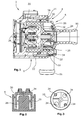
- FIG. 1 shows a sectional view of a motor vehicle coolant pump according to the invention 2.
- the motor vehicle coolant pump 2 in this case has a multi-part housing 4 made of plastic, in which substantially a motor unit 6 and a pump unit 8 are provided.
- the pump unit 8 consists essentially of an impeller member 10 with molded blade elements 12.
- a pressure build-up is effected by the impeller member 10 in the housing part 14 of the pump unit 8, wherein cooling fluid can be supplied via an inlet port 16 and via an outlet port 18 can be discharged.
- the impeller member 10 of the pump unit 8 is integrally connected to a cylindrical drive member 20 of the motor unit 6 and thus forms a cup-shaped motor rotor 22.
- Such an arrangement is commonly referred to as external rotor.
- the motor rotor 22 is in this case mounted via bearing means 24 in a containment shell 26 of the housing 4 in a known manner.
- the motor rotor 22 forms an electronically commutated electric motor, wherein embedded permanent magnets (not shown further) are provided in the drive member 20 of the motor rotor, so that the motor rotor 22 is entrained by the rotationally moving magnetic field that can be generated in the stator unit 28 and is rotating is offset.
- an inlet opening 30 for a motor unit 6 to be cooled cooling fluid in the present embodiment an annular gap between the housing 4, here between the housing part 14 and the cylindrical drive member 20 is provided.
- the cooling fluid is thus conveyed via this inlet opening 30 from a pressure side 32 of the pump unit 8 into a gap between the cylindrical drive member 20 and the containment shell 18 toward outlet openings 34 to a suction side 36 of the pump unit 8.
- Any dirt particles present in the cooling fluid are collected due to their centrifugal force in the transition 38 between the cylindrical drive member 20 and the impeller member 10, so that they can not damage the motor unit 6 and in particular the bearing means 24.
- FIG. 2 3 shows a schematic view of the flow of cooling fluid from the inlet opening 30 between the housing 4 and the drive member 20 through a gap between the drive member 20 and the containment shell 26 toward the outlet openings 34.
- FIG. 3 shows again in a perspective view of the motor rotor 22 with the impeller member 10 and the outlet openings 34, which are designed here as bores, which are arranged in a circle, offset by 90 °.
Landscapes
- Engineering & Computer Science (AREA)
- Mechanical Engineering (AREA)
- General Engineering & Computer Science (AREA)
- Physics & Mathematics (AREA)
- Thermal Sciences (AREA)
- Structures Of Non-Positive Displacement Pumps (AREA)
Abstract
Description
- Die Erfindung betrifft eine elektrische KFZ-Kühlmittelpumpe mit einem Gehäuse, das eine Pumpeneinheit und eine Motoreinheit aufweist, wobei die Motoreinheit einen mittels Lagermitteln im Gehäuse gelagerten Motorrotor sowie einen Motorstator besitzt, wobei der Motorrotor ein Laufradorgan mit Schaufelelementen der Pumpeneinheit und ein in Axialrichtung verlaufendes Antriebsorgan aufweist, wobei Einlass- und Auslassöffnungen vorgesehen sind, die ein Durchströmen der Motoreinheit mit einem Kühlfluid von einer Druckseite der Pumpeneinheit zu einer Saugseite der Pumpeneinheit ermöglicht.
- Derartige elektrische KFZ-Kühlmittelpumpen sind aus dem Stand der Technik hinlänglich bekannt. So offenbart die
DE 199 48 972 A1 eine Motorpumpe mit einer Pumpeneinheit und einer Motoreinheit, wobei die Motoreinheit einen als Außenläufer gestalteten Motorrotor besitzt, der ein Laufradorgan mit Schaufelelementen besitzt. Zur Kühlung der Motoreinheit ist es bekannt, zu pumpendes Kühlfluid von einer Druckseite der Pumpeneinheit durch die Motoreinheit hin zu einer Saugseite der Pumpeneinheit zu führen. Gemäß derDE 199 48 972 A1 ist hier eine Öffnung im Gehäuse im Bereich der Pumpeneinheit vorgesehen, durch die das Kühlfluid in die Motoreinheit dringt, wobei das Kühlfluid die Motoreinheit über eine hohl ausgeführte Motorrotorwelle wieder verlässt. Des Weiteren ist es bekannt, dass das Kühlfluid die Motoreinheit über Öffnungen im Lagerbereich der Motorrotorwelle verlässt. In beiden Fällen kann die Funktion und Lebensdauer der KFZ-Kühlmittelpumpe durch Ablagerungen von im Kühlfluid befindlichen Teilchen, wie zum Beispiel Gießsand, beeinträchtigt werden. Insbesondere bei einer Ableitung des Kühlfluids durch den Lagerbereich kommt es zu einer hydroabrasiven Strömung, die zu einem hohen radialen und axialen Lagerverschleiß führt. - Aufgabe der Erfindung ist es daher, den oben genannten Nachteil auf einfache und kostengünstige Weise zu vermeiden.
- Diese Aufgabe wird erfindungsgemäß dadurch gelöst, dass im Laufradorgan die Auslassöffnungen zur fluidischen Verbindung mit der Saugseite der Pumpeneinheit vorgesehen sind. Durch das Vorsehen dieser Öffnungen im Laufrad wird den vorhandenen Schmutzteilchen die Möglichkeit gegeben, mit der Strömung über die Auslassöffnung zu entweichen, ohne in den kritischen Lagerbereich zu gelangen. werden vorhandene Schmutzteilchen durch die Zentrifugalkraft vom Lagerbereich der Motorrotorwelle weggeführt.
- In einer besonders vorteilhaften Ausführungsform ist der Motorrotor topfförmig ausgebildet, wobei das Antriebsorgan zylinderförmig ausgebildet ist. Hierbei können sich dann eventuell vorhandene Schmutzteilchen im Topfbereich des Motorrotors sammeln, ohne schädigend auf die Motoreinheit einzuwirken. Hierbei ist es besonders vorteilhaft, wenn der Motorrotor ein Außenläufer ist.
- In vorteilhafter Weise ist die Motoreinheit ein elektronisch kommutierter Elektromotor. Um eine optimale Durchströmung zu gewährleisten, ist es vorteilhaft, wenn die Öffnungen im Bereich der vom Motormittelpunkt abgewandten Enden der Schaufelelemente angeordnet sind. Hierbei ist es besonders vorteilhaft, wenn die Öffnungen als Bohrungen ausgeführt sind, die kreisförmig, um 90° versetzt, angeordnet sind. Hierdurch findet eine auf die Lagermittel einwirkende Axialschubentlastung statt, was sich weiterhin positiv auf die Lebensdauer der Lagermittel auswirkt.
- Des Weiteren kann in vorteilhafter Weise die Einlassöffnung als ringförmiger Spalt zwischen dem Gehäuse und dem zylinderförmigen Antriebsorgan ausgeführt sind. Insbesondere beim Nassläuferprinzip ergibt sich naturgemäß ein ringförmiger Spalt zwischen dem zylinderförmigen Antriebsorgan und dem Gehäuse, welcher auf einfache Weise die Eintrittsöffnung ausbildet.
- Die Erfindung wird nachfolgend anhand einer Zeichnung näher erläutert, hierbei zeigt:
-
Figur 1 eine Schnittansicht einer erfindungsgemäßen KFZ-Kühlmittelpumpen, -
Figur 2 eine schematische Schnittansicht der KFZ-Kühlmittelpumpe ausFig. 1 , und -
Figur 3 eine perspektivische Ansicht eines Motorrotors mit Laufradorgan. -
Figur 1 zeigt in einer Schnittansicht eine erfindungsgemäße KFZ-Kühlmittelpumpe 2. Die KFZ-Kühlmittelpumpe 2 weist hierbei ein mehrteiliges Gehäuse 4 aus Kunststoff auf, in dem im Wesentlichen eine Motoreinheit 6 und eine Pumpeneinheit 8 vorgesehen sind. Die Pumpeneinheit 8 besteht im Wesentlichen aus einem Laufradorgan 10 mit angeformten Schaufelelementen 12. Auf bekannte Weise wird durch das Laufradorgan 10 im Gehäuseteil 14 der Pumpeneinheit 8 ein Druckaufbau bewirkt, wobei Kühlfluid über einen Einlassanschluss 16 zuführbar und über einen Auslassanschluss 18 abführbar ist. Das Laufradorgan 10 der Pumpeneinheit 8 ist einstückig mit einem zylindrischen Antriebsorgan 20 der Motoreinheit 6 verbunden und bildet auf diese Weise einen topfförmigen Motorrotor 22. Eine derartige Anordnung wird üblicher Weise als Außenläufer bezeichnet. Der Motorrotor 22 ist hierbei über Lagermittel 24 in einem Spalttopf 26 des Gehäuses 4 auf bekannte Weise gelagert. Der Motorrotor 22 bildet also hier zusammen mit einer Statoreinheit 28 einen elektronisch kommutierten Elektromotor, wobei im Antriebsorgan 20 des Motorrotors 22 nicht weiter dargestellte eingebettete Permanentmagnete vorgesehen sind, so dass der Motorrotor 22 durch das in der Statoreinheit 28 erzeugbare rotatorisch wandernde Magnetfeld mitgeschleppt und in Drehung versetzt wird. Als Einlassöffnung 30 für ein die Motoreinheit 6 zu kühlendes Kühlfluid ist im vorliegenden Ausführungsbeispiel ein ringförmiger Spalt zwischen dem Gehäuse 4, hier zwischen dem Gehäuseteil 14 und dem zylinderförmigen Antriebsorgan 20 vorgesehen. Das Kühlfluid wird also über diese Einlassöffnung 30 von einer Druckseite 32 der Pumpeneinheit 8 in einen Spalt zwischen dem zylinderförmigen Antriebsorgan 20 und dem Spalttopf 18 hin zu Auslassöffnungen 34 zu einer Saugseite 36 der Pumpeneinheit 8 gefördert. Eventuell im Kühlfluid vorhandene Schmutzpartikel werden aufgrund ihrer Zentrifugalkraft im Übergang 38 zwischen dem zylinderförmigen Antriebsorgan 20 und dem Laufradorgan 10 gesammelt, so dass sie die Motoreinheit 6 und hier insbesondere die Lagermittel 24 nicht schädigen können. -
Figur 2 zeigt in einer schematischen Ansicht den Kühlfluidstrom von der Einlassöffnung 30 zwischen dem Gehäuse 4 und dem Antriebsorgan 20 über einen Spalt zwischen dem Antriebsorgan 20 und dem Spalttopf 26 hin zu den Auslassöffnungen 34. -
Figur 3 zeigt noch einmal in einer perspektivischen Ansicht den Motorrotor 22 mit dem Laufradorgan 10 und den Auslassöffnungen 34, die hier als Bohrungen ausgeführt sind, die kreisförmig, um 90° versetzt, angeordnet sind.
Claims (7)
- Elektrische KFZ-Kühlmittelpumpe mit einem Gehäuse (4), das eine Pumpeneinheit (8) und eine Motoreinheit (6) aufweist, wobei die Motoreinheit (6) einen mittels Lagermitteln (24) im Gehäuse (4) gelagerten Motorrotor (22) sowie einen Motorstator (20) besitzt, wobei der Motorrotor (22) ein Laufradorgan (10) mit Schaufelelementen (12) der Pumpeneinheit (8) und ein in Axialrichtung verlaufendes Antriebsorgan (20) aufweist, wobei Einlass- und Auslassöffnungen (30, 34) vorgesehen sind, die ein Durchströmen der Motoreinheit (6) mit einem Kühlfluid von einer Druckseite (24) der Pumpeneinheit (8) zu einer Saugseite (25) der Pumpeneinheit ermöglicht, dadurch gekennzeichnet, das im Laufradorgan (10) die Auslassöffnungen (34) zur fluidischen Verbindung mit der Saugseite (36) der Pumpeneinheit (8) vorgesehen sind.
- Elektrische KFZ-Kühlmittelpumpe nach Anspruch 1, dadurch gekennzeichnet, dass der Motorrotor (22) topfförmig ausgebildet ist, wobei das Antriebsorgan (20) zylinderförmig ausgebildet ist.
- Elektrische KFZ-Kühlmittelpumpe nach Anspruch 2, dadurch gekennzeichnet, dass der Motorrotor (22) ein Außenläufer ist.
- Elektrische KFZ-Kühlmittelpumpe nach einem der Ansprüche 1 - 3, dadurch gekennzeichnet, dass die Motoreinheit (6) ein elektronisch kommutierter Elektromotor ist.
- Elektrische KFZ-Kühlmittelpumpe nach einem der vorherigen Ansprüche, dadurch gekennzeichnet, dass die Auslassöffnungen (34) im Bereich der vom Motorrotormittelpunkt abgewandten Enden der Schaufelelemente (12) angeordnet sind.
- Elektrische KFZ-Kühlmittelpumpe nach Anspruch 5, dadurch gekennzeichnet, dass die Auslassöffnungen (34) als Bohrungen ausgeführt sind, die kreisförmig, um 90° versetzt angeordnet sind.
- Elektrische KFZ-Kühlmittelpumpe nach einem der Ansprüche 4 - 6, dadurch gekennzeichnet, dass die Einlassöffnung (30) als ringförmiger Spalt zwischen dem Gehäuse (4) und dem zylinderförmigen Antriebsorgan (20) ausgeführt ist.
Priority Applications (1)
| Application Number | Priority Date | Filing Date | Title |
|---|---|---|---|
| EP14189767.8A EP3012457B1 (de) | 2014-10-21 | 2014-10-21 | Elektrische kfz-kühlmittelpumpe |
Applications Claiming Priority (1)
| Application Number | Priority Date | Filing Date | Title |
|---|---|---|---|
| EP14189767.8A EP3012457B1 (de) | 2014-10-21 | 2014-10-21 | Elektrische kfz-kühlmittelpumpe |
Publications (2)
| Publication Number | Publication Date |
|---|---|
| EP3012457A1 true EP3012457A1 (de) | 2016-04-27 |
| EP3012457B1 EP3012457B1 (de) | 2018-12-12 |
Family
ID=51830190
Family Applications (1)
| Application Number | Title | Priority Date | Filing Date |
|---|---|---|---|
| EP14189767.8A Active EP3012457B1 (de) | 2014-10-21 | 2014-10-21 | Elektrische kfz-kühlmittelpumpe |
Country Status (1)
| Country | Link |
|---|---|
| EP (1) | EP3012457B1 (de) |
Cited By (2)
| Publication number | Priority date | Publication date | Assignee | Title |
|---|---|---|---|---|
| DE102016122784A1 (de) | 2016-11-25 | 2018-05-30 | Pierburg Pump Technology Gmbh | Elektrische KFZ-Kühlmittelpumpe |
| CN110566516A (zh) * | 2019-09-27 | 2019-12-13 | 汉宇集团股份有限公司 | 一种可冷却电路板的汽车电子水泵 |
Citations (5)
| Publication number | Priority date | Publication date | Assignee | Title |
|---|---|---|---|---|
| EP0913910A1 (de) * | 1997-10-31 | 1999-05-06 | Siemens Canada Limited | Pumpenmotor mit Flüssigkeitskühlungsystem |
| DE19948972A1 (de) | 1999-10-12 | 2001-04-19 | Bosch Gmbh Robert | Motorpumpe |
| US20040234395A1 (en) * | 2003-05-20 | 2004-11-25 | Makoto Hatano | Magnetic coupling pump |
| DE102009009898A1 (de) * | 2009-02-20 | 2010-08-26 | Bayerische Motoren Werke Aktiengesellschaft | Kühlmittelpumpe für Fahrzeuge |
| DE102011117183A1 (de) * | 2011-10-28 | 2012-08-02 | Ruhrpumpen Gmbh | Teilstromführung, insbesondere einer Magnetkupplungspumpe |
-
2014
- 2014-10-21 EP EP14189767.8A patent/EP3012457B1/de active Active
Patent Citations (5)
| Publication number | Priority date | Publication date | Assignee | Title |
|---|---|---|---|---|
| EP0913910A1 (de) * | 1997-10-31 | 1999-05-06 | Siemens Canada Limited | Pumpenmotor mit Flüssigkeitskühlungsystem |
| DE19948972A1 (de) | 1999-10-12 | 2001-04-19 | Bosch Gmbh Robert | Motorpumpe |
| US20040234395A1 (en) * | 2003-05-20 | 2004-11-25 | Makoto Hatano | Magnetic coupling pump |
| DE102009009898A1 (de) * | 2009-02-20 | 2010-08-26 | Bayerische Motoren Werke Aktiengesellschaft | Kühlmittelpumpe für Fahrzeuge |
| DE102011117183A1 (de) * | 2011-10-28 | 2012-08-02 | Ruhrpumpen Gmbh | Teilstromführung, insbesondere einer Magnetkupplungspumpe |
Cited By (4)
| Publication number | Priority date | Publication date | Assignee | Title |
|---|---|---|---|---|
| DE102016122784A1 (de) | 2016-11-25 | 2018-05-30 | Pierburg Pump Technology Gmbh | Elektrische KFZ-Kühlmittelpumpe |
| WO2018095607A1 (de) | 2016-11-25 | 2018-05-31 | Pierburg Pump Technology Gmbh | Elektrische kfz-kühlmittelpumpe |
| US11162511B2 (en) | 2016-11-25 | 2021-11-02 | Pierburg Pump Technology Gmbh | Electric motor-vehicle coolant pump |
| CN110566516A (zh) * | 2019-09-27 | 2019-12-13 | 汉宇集团股份有限公司 | 一种可冷却电路板的汽车电子水泵 |
Also Published As
| Publication number | Publication date |
|---|---|
| EP3012457B1 (de) | 2018-12-12 |
Similar Documents
| Publication | Publication Date | Title |
|---|---|---|
| EP3545196B1 (de) | Elektrische kfz-kühlmittelpumpe | |
| EP3374642B1 (de) | Elektrische kfz-axial-flüssigkeitspumpe | |
| EP2211444B1 (de) | Elektromotor mit Kühlventilatorwirkung | |
| DE102014201487B3 (de) | Kreiselpumpenlaufrad | |
| EP2566015B1 (de) | Elektromotor | |
| WO2010028921A1 (de) | Regelbare kühlmittelpumpe | |
| DE102016209312A1 (de) | Elektrische kreiselpumpe | |
| EP2015972A1 (de) | Hydrodynamische maschine | |
| DE102012212423A1 (de) | Flüssigkeitspumpe | |
| EP1834397B1 (de) | Elektrohandwerkzeugmaschine | |
| EP3012457B1 (de) | Elektrische kfz-kühlmittelpumpe | |
| EP2322803B1 (de) | Pumpe mit einer magnetkupplung | |
| DE102014201880B3 (de) | Schmutzfänger als Funktionsmodul im Flügelrad einer Kühlmittelpumpe | |
| EP0013942B1 (de) | Kreiselpumpe für mit Feststoffen versetzte Flüssigkeiten | |
| DE102015211759A1 (de) | Flügelzellenpumpe zum Erzeugen eines Unterdrucks | |
| EP3006742B1 (de) | Elektrische Kfz-Kühlmittelpumpe | |
| WO2012152599A1 (de) | Pumpenaggregat | |
| EP2535590A2 (de) | Kreiselpumpe mit integriertem Schneidwerk | |
| WO2015110256A1 (de) | Elektromotorische wasserpumpe | |
| DE102021133447A1 (de) | Magnetkupplungspumpenanordnung | |
| WO2017021117A1 (de) | Verdrängerpumpe zur förderung eines fluides für einen verbraucher eines kraftfahrzeuges | |
| EP2205850A1 (de) | Kraftstoffpumpe zum fördern von kraftstoff aus einem vorratsbehälter zu einer brennkraftmaschine | |
| EP2227638B1 (de) | Zentrifugalpumpe mit einer erhöhten betriebssicherheit | |
| DE102013211181B3 (de) | Pumpe | |
| EP3546759A1 (de) | Umwälzpumpe mit motorlüfter |
Legal Events
| Date | Code | Title | Description |
|---|---|---|---|
| PUAI | Public reference made under article 153(3) epc to a published international application that has entered the european phase |
Free format text: ORIGINAL CODE: 0009012 |
|
| AK | Designated contracting states |
Kind code of ref document: A1 Designated state(s): AL AT BE BG CH CY CZ DE DK EE ES FI FR GB GR HR HU IE IS IT LI LT LU LV MC MK MT NL NO PL PT RO RS SE SI SK SM TR |
|
| AX | Request for extension of the european patent |
Extension state: BA ME |
|
| 17P | Request for examination filed |
Effective date: 20161019 |
|
| RBV | Designated contracting states (corrected) |
Designated state(s): AL AT BE BG CH CY CZ DE DK EE ES FI FR GB GR HR HU IE IS IT LI LT LU LV MC MK MT NL NO PL PT RO RS SE SI SK SM TR |
|
| GRAP | Despatch of communication of intention to grant a patent |
Free format text: ORIGINAL CODE: EPIDOSNIGR1 |
|
| STAA | Information on the status of an ep patent application or granted ep patent |
Free format text: STATUS: GRANT OF PATENT IS INTENDED |
|
| INTG | Intention to grant announced |
Effective date: 20180802 |
|
| GRAS | Grant fee paid |
Free format text: ORIGINAL CODE: EPIDOSNIGR3 |
|
| GRAA | (expected) grant |
Free format text: ORIGINAL CODE: 0009210 |
|
| STAA | Information on the status of an ep patent application or granted ep patent |
Free format text: STATUS: THE PATENT HAS BEEN GRANTED |
|
| AK | Designated contracting states |
Kind code of ref document: B1 Designated state(s): AL AT BE BG CH CY CZ DE DK EE ES FI FR GB GR HR HU IE IS IT LI LT LU LV MC MK MT NL NO PL PT RO RS SE SI SK SM TR |
|
| REG | Reference to a national code |
Ref country code: GB Ref legal event code: FG4D Free format text: NOT ENGLISH |
|
| REG | Reference to a national code |
Ref country code: CH Ref legal event code: EP |
|
| REG | Reference to a national code |
Ref country code: AT Ref legal event code: REF Ref document number: 1076385 Country of ref document: AT Kind code of ref document: T Effective date: 20181215 |
|
| REG | Reference to a national code |
Ref country code: DE Ref legal event code: R096 Ref document number: 502014010303 Country of ref document: DE |
|
| REG | Reference to a national code |
Ref country code: IE Ref legal event code: FG4D Free format text: LANGUAGE OF EP DOCUMENT: GERMAN |
|
| REG | Reference to a national code |
Ref country code: NL Ref legal event code: MP Effective date: 20181212 |
|
| REG | Reference to a national code |
Ref country code: LT Ref legal event code: MG4D |
|
| PG25 | Lapsed in a contracting state [announced via postgrant information from national office to epo] |
Ref country code: NO Free format text: LAPSE BECAUSE OF FAILURE TO SUBMIT A TRANSLATION OF THE DESCRIPTION OR TO PAY THE FEE WITHIN THE PRESCRIBED TIME-LIMIT Effective date: 20190312 Ref country code: LT Free format text: LAPSE BECAUSE OF FAILURE TO SUBMIT A TRANSLATION OF THE DESCRIPTION OR TO PAY THE FEE WITHIN THE PRESCRIBED TIME-LIMIT Effective date: 20181212 Ref country code: HR Free format text: LAPSE BECAUSE OF FAILURE TO SUBMIT A TRANSLATION OF THE DESCRIPTION OR TO PAY THE FEE WITHIN THE PRESCRIBED TIME-LIMIT Effective date: 20181212 Ref country code: BG Free format text: LAPSE BECAUSE OF FAILURE TO SUBMIT A TRANSLATION OF THE DESCRIPTION OR TO PAY THE FEE WITHIN THE PRESCRIBED TIME-LIMIT Effective date: 20190312 Ref country code: FI Free format text: LAPSE BECAUSE OF FAILURE TO SUBMIT A TRANSLATION OF THE DESCRIPTION OR TO PAY THE FEE WITHIN THE PRESCRIBED TIME-LIMIT Effective date: 20181212 Ref country code: LV Free format text: LAPSE BECAUSE OF FAILURE TO SUBMIT A TRANSLATION OF THE DESCRIPTION OR TO PAY THE FEE WITHIN THE PRESCRIBED TIME-LIMIT Effective date: 20181212 Ref country code: ES Free format text: LAPSE BECAUSE OF FAILURE TO SUBMIT A TRANSLATION OF THE DESCRIPTION OR TO PAY THE FEE WITHIN THE PRESCRIBED TIME-LIMIT Effective date: 20181212 |
|
| PG25 | Lapsed in a contracting state [announced via postgrant information from national office to epo] |
Ref country code: GR Free format text: LAPSE BECAUSE OF FAILURE TO SUBMIT A TRANSLATION OF THE DESCRIPTION OR TO PAY THE FEE WITHIN THE PRESCRIBED TIME-LIMIT Effective date: 20190313 Ref country code: RS Free format text: LAPSE BECAUSE OF FAILURE TO SUBMIT A TRANSLATION OF THE DESCRIPTION OR TO PAY THE FEE WITHIN THE PRESCRIBED TIME-LIMIT Effective date: 20181212 Ref country code: AL Free format text: LAPSE BECAUSE OF FAILURE TO SUBMIT A TRANSLATION OF THE DESCRIPTION OR TO PAY THE FEE WITHIN THE PRESCRIBED TIME-LIMIT Effective date: 20181212 Ref country code: SE Free format text: LAPSE BECAUSE OF FAILURE TO SUBMIT A TRANSLATION OF THE DESCRIPTION OR TO PAY THE FEE WITHIN THE PRESCRIBED TIME-LIMIT Effective date: 20181212 |
|
| PG25 | Lapsed in a contracting state [announced via postgrant information from national office to epo] |
Ref country code: NL Free format text: LAPSE BECAUSE OF FAILURE TO SUBMIT A TRANSLATION OF THE DESCRIPTION OR TO PAY THE FEE WITHIN THE PRESCRIBED TIME-LIMIT Effective date: 20181212 |
|
| PG25 | Lapsed in a contracting state [announced via postgrant information from national office to epo] |
Ref country code: PL Free format text: LAPSE BECAUSE OF FAILURE TO SUBMIT A TRANSLATION OF THE DESCRIPTION OR TO PAY THE FEE WITHIN THE PRESCRIBED TIME-LIMIT Effective date: 20181212 Ref country code: CZ Free format text: LAPSE BECAUSE OF FAILURE TO SUBMIT A TRANSLATION OF THE DESCRIPTION OR TO PAY THE FEE WITHIN THE PRESCRIBED TIME-LIMIT Effective date: 20181212 Ref country code: PT Free format text: LAPSE BECAUSE OF FAILURE TO SUBMIT A TRANSLATION OF THE DESCRIPTION OR TO PAY THE FEE WITHIN THE PRESCRIBED TIME-LIMIT Effective date: 20190412 |
|
| PG25 | Lapsed in a contracting state [announced via postgrant information from national office to epo] |
Ref country code: SK Free format text: LAPSE BECAUSE OF FAILURE TO SUBMIT A TRANSLATION OF THE DESCRIPTION OR TO PAY THE FEE WITHIN THE PRESCRIBED TIME-LIMIT Effective date: 20181212 Ref country code: EE Free format text: LAPSE BECAUSE OF FAILURE TO SUBMIT A TRANSLATION OF THE DESCRIPTION OR TO PAY THE FEE WITHIN THE PRESCRIBED TIME-LIMIT Effective date: 20181212 Ref country code: SM Free format text: LAPSE BECAUSE OF FAILURE TO SUBMIT A TRANSLATION OF THE DESCRIPTION OR TO PAY THE FEE WITHIN THE PRESCRIBED TIME-LIMIT Effective date: 20181212 Ref country code: RO Free format text: LAPSE BECAUSE OF FAILURE TO SUBMIT A TRANSLATION OF THE DESCRIPTION OR TO PAY THE FEE WITHIN THE PRESCRIBED TIME-LIMIT Effective date: 20181212 Ref country code: IS Free format text: LAPSE BECAUSE OF FAILURE TO SUBMIT A TRANSLATION OF THE DESCRIPTION OR TO PAY THE FEE WITHIN THE PRESCRIBED TIME-LIMIT Effective date: 20190412 |
|
| REG | Reference to a national code |
Ref country code: DE Ref legal event code: R097 Ref document number: 502014010303 Country of ref document: DE |
|
| PLBE | No opposition filed within time limit |
Free format text: ORIGINAL CODE: 0009261 |
|
| STAA | Information on the status of an ep patent application or granted ep patent |
Free format text: STATUS: NO OPPOSITION FILED WITHIN TIME LIMIT |
|
| PG25 | Lapsed in a contracting state [announced via postgrant information from national office to epo] |
Ref country code: SI Free format text: LAPSE BECAUSE OF FAILURE TO SUBMIT A TRANSLATION OF THE DESCRIPTION OR TO PAY THE FEE WITHIN THE PRESCRIBED TIME-LIMIT Effective date: 20181212 Ref country code: DK Free format text: LAPSE BECAUSE OF FAILURE TO SUBMIT A TRANSLATION OF THE DESCRIPTION OR TO PAY THE FEE WITHIN THE PRESCRIBED TIME-LIMIT Effective date: 20181212 |
|
| 26N | No opposition filed |
Effective date: 20190913 |
|
| REG | Reference to a national code |
Ref country code: DE Ref legal event code: R082 Ref document number: 502014010303 Country of ref document: DE Representative=s name: TERPATENT PARTGMBB, DE Ref country code: DE Ref legal event code: R082 Ref document number: 502014010303 Country of ref document: DE Representative=s name: TERPATENT PATENTANWAELTE TER SMITTEN EBERLEIN-, DE |
|
| PG25 | Lapsed in a contracting state [announced via postgrant information from national office to epo] |
Ref country code: TR Free format text: LAPSE BECAUSE OF FAILURE TO SUBMIT A TRANSLATION OF THE DESCRIPTION OR TO PAY THE FEE WITHIN THE PRESCRIBED TIME-LIMIT Effective date: 20181212 |
|
| PG25 | Lapsed in a contracting state [announced via postgrant information from national office to epo] |
Ref country code: MC Free format text: LAPSE BECAUSE OF FAILURE TO SUBMIT A TRANSLATION OF THE DESCRIPTION OR TO PAY THE FEE WITHIN THE PRESCRIBED TIME-LIMIT Effective date: 20181212 |
|
| REG | Reference to a national code |
Ref country code: CH Ref legal event code: PL |
|
| PG25 | Lapsed in a contracting state [announced via postgrant information from national office to epo] |
Ref country code: LI Free format text: LAPSE BECAUSE OF NON-PAYMENT OF DUE FEES Effective date: 20191031 Ref country code: LU Free format text: LAPSE BECAUSE OF NON-PAYMENT OF DUE FEES Effective date: 20191021 Ref country code: CH Free format text: LAPSE BECAUSE OF NON-PAYMENT OF DUE FEES Effective date: 20191031 |
|
| REG | Reference to a national code |
Ref country code: BE Ref legal event code: MM Effective date: 20191031 |
|
| PG25 | Lapsed in a contracting state [announced via postgrant information from national office to epo] |
Ref country code: BE Free format text: LAPSE BECAUSE OF NON-PAYMENT OF DUE FEES Effective date: 20191031 |
|
| GBPC | Gb: european patent ceased through non-payment of renewal fee |
Effective date: 20191021 |
|
| PG25 | Lapsed in a contracting state [announced via postgrant information from national office to epo] |
Ref country code: IE Free format text: LAPSE BECAUSE OF NON-PAYMENT OF DUE FEES Effective date: 20191021 Ref country code: GB Free format text: LAPSE BECAUSE OF NON-PAYMENT OF DUE FEES Effective date: 20191021 |
|
| REG | Reference to a national code |
Ref country code: AT Ref legal event code: MM01 Ref document number: 1076385 Country of ref document: AT Kind code of ref document: T Effective date: 20191021 |
|
| PG25 | Lapsed in a contracting state [announced via postgrant information from national office to epo] |
Ref country code: AT Free format text: LAPSE BECAUSE OF NON-PAYMENT OF DUE FEES Effective date: 20191021 |
|
| PG25 | Lapsed in a contracting state [announced via postgrant information from national office to epo] |
Ref country code: CY Free format text: LAPSE BECAUSE OF FAILURE TO SUBMIT A TRANSLATION OF THE DESCRIPTION OR TO PAY THE FEE WITHIN THE PRESCRIBED TIME-LIMIT Effective date: 20181212 |
|
| PG25 | Lapsed in a contracting state [announced via postgrant information from national office to epo] |
Ref country code: MT Free format text: LAPSE BECAUSE OF FAILURE TO SUBMIT A TRANSLATION OF THE DESCRIPTION OR TO PAY THE FEE WITHIN THE PRESCRIBED TIME-LIMIT Effective date: 20181212 Ref country code: HU Free format text: LAPSE BECAUSE OF FAILURE TO SUBMIT A TRANSLATION OF THE DESCRIPTION OR TO PAY THE FEE WITHIN THE PRESCRIBED TIME-LIMIT; INVALID AB INITIO Effective date: 20141021 |
|
| PG25 | Lapsed in a contracting state [announced via postgrant information from national office to epo] |
Ref country code: MK Free format text: LAPSE BECAUSE OF FAILURE TO SUBMIT A TRANSLATION OF THE DESCRIPTION OR TO PAY THE FEE WITHIN THE PRESCRIBED TIME-LIMIT Effective date: 20181212 |
|
| PGFP | Annual fee paid to national office [announced via postgrant information from national office to epo] |
Ref country code: DE Payment date: 20251021 Year of fee payment: 12 |
|
| PGFP | Annual fee paid to national office [announced via postgrant information from national office to epo] |
Ref country code: IT Payment date: 20251024 Year of fee payment: 12 |
|
| PGFP | Annual fee paid to national office [announced via postgrant information from national office to epo] |
Ref country code: FR Payment date: 20251030 Year of fee payment: 12 |
|
| REG | Reference to a national code |
Ref country code: DE Ref legal event code: R082 Ref document number: 502014010303 Country of ref document: DE |