EP3012090A1 - Device for plasma treating surfaces and a method for treating surfaces containing plasma - Google Patents
Device for plasma treating surfaces and a method for treating surfaces containing plasma Download PDFInfo
- Publication number
- EP3012090A1 EP3012090A1 EP15188751.0A EP15188751A EP3012090A1 EP 3012090 A1 EP3012090 A1 EP 3012090A1 EP 15188751 A EP15188751 A EP 15188751A EP 3012090 A1 EP3012090 A1 EP 3012090A1
- Authority
- EP
- European Patent Office
- Prior art keywords
- electrode
- process gas
- plasma
- electrodes
- electric field
- Prior art date
- Legal status (The legal status is an assumption and is not a legal conclusion. Google has not performed a legal analysis and makes no representation as to the accuracy of the status listed.)
- Withdrawn
Links
Images

Classifications
-
- H—ELECTRICITY
- H01—ELECTRIC ELEMENTS
- H01J—ELECTRIC DISCHARGE TUBES OR DISCHARGE LAMPS
- H01J37/00—Discharge tubes with provision for introducing objects or material to be exposed to the discharge, e.g. for the purpose of examination or processing thereof
- H01J37/32—Gas-filled discharge tubes
- H01J37/32431—Constructional details of the reactor
- H01J37/32798—Further details of plasma apparatus not provided for in groups H01J37/3244 - H01J37/32788; special provisions for cleaning or maintenance of the apparatus
- H01J37/32807—Construction (includes replacing parts of the apparatus)
-
- H—ELECTRICITY
- H01—ELECTRIC ELEMENTS
- H01J—ELECTRIC DISCHARGE TUBES OR DISCHARGE LAMPS
- H01J37/00—Discharge tubes with provision for introducing objects or material to be exposed to the discharge, e.g. for the purpose of examination or processing thereof
- H01J37/32—Gas-filled discharge tubes
- H01J37/32431—Constructional details of the reactor
- H01J37/32532—Electrodes
- H01J37/32568—Relative arrangement or disposition of electrodes; moving means
-
- B—PERFORMING OPERATIONS; TRANSPORTING
- B29—WORKING OF PLASTICS; WORKING OF SUBSTANCES IN A PLASTIC STATE IN GENERAL
- B29C—SHAPING OR JOINING OF PLASTICS; SHAPING OF MATERIAL IN A PLASTIC STATE, NOT OTHERWISE PROVIDED FOR; AFTER-TREATMENT OF THE SHAPED PRODUCTS, e.g. REPAIRING
- B29C59/00—Surface shaping of articles, e.g. embossing; Apparatus therefor
- B29C59/14—Surface shaping of articles, e.g. embossing; Apparatus therefor by plasma treatment
-
- C—CHEMISTRY; METALLURGY
- C09—DYES; PAINTS; POLISHES; NATURAL RESINS; ADHESIVES; COMPOSITIONS NOT OTHERWISE PROVIDED FOR; APPLICATIONS OF MATERIALS NOT OTHERWISE PROVIDED FOR
- C09J—ADHESIVES; NON-MECHANICAL ASPECTS OF ADHESIVE PROCESSES IN GENERAL; ADHESIVE PROCESSES NOT PROVIDED FOR ELSEWHERE; USE OF MATERIALS AS ADHESIVES
- C09J5/00—Adhesive processes in general; Adhesive processes not provided for elsewhere, e.g. relating to primers
- C09J5/02—Adhesive processes in general; Adhesive processes not provided for elsewhere, e.g. relating to primers involving pretreatment of the surfaces to be joined
-
- H—ELECTRICITY
- H01—ELECTRIC ELEMENTS
- H01J—ELECTRIC DISCHARGE TUBES OR DISCHARGE LAMPS
- H01J37/00—Discharge tubes with provision for introducing objects or material to be exposed to the discharge, e.g. for the purpose of examination or processing thereof
- H01J37/32—Gas-filled discharge tubes
- H01J37/32431—Constructional details of the reactor
- H01J37/3244—Gas supply means
-
- H—ELECTRICITY
- H01—ELECTRIC ELEMENTS
- H01J—ELECTRIC DISCHARGE TUBES OR DISCHARGE LAMPS
- H01J37/00—Discharge tubes with provision for introducing objects or material to be exposed to the discharge, e.g. for the purpose of examination or processing thereof
- H01J37/32—Gas-filled discharge tubes
- H01J37/32431—Constructional details of the reactor
- H01J37/32532—Electrodes
- H01J37/32541—Shape
-
- H—ELECTRICITY
- H05—ELECTRIC TECHNIQUES NOT OTHERWISE PROVIDED FOR
- H05H—PLASMA TECHNIQUE; PRODUCTION OF ACCELERATED ELECTRICALLY-CHARGED PARTICLES OR OF NEUTRONS; PRODUCTION OR ACCELERATION OF NEUTRAL MOLECULAR OR ATOMIC BEAMS
- H05H1/00—Generating plasma; Handling plasma
- H05H1/24—Generating plasma
- H05H1/2406—Generating plasma using dielectric barrier discharges, i.e. with a dielectric interposed between the electrodes
-
- B—PERFORMING OPERATIONS; TRANSPORTING
- B05—SPRAYING OR ATOMISING IN GENERAL; APPLYING FLUENT MATERIALS TO SURFACES, IN GENERAL
- B05D—PROCESSES FOR APPLYING FLUENT MATERIALS TO SURFACES, IN GENERAL
- B05D3/00—Pretreatment of surfaces to which liquids or other fluent materials are to be applied; After-treatment of applied coatings, e.g. intermediate treating of an applied coating preparatory to subsequent applications of liquids or other fluent materials
- B05D3/14—Pretreatment of surfaces to which liquids or other fluent materials are to be applied; After-treatment of applied coatings, e.g. intermediate treating of an applied coating preparatory to subsequent applications of liquids or other fluent materials by electrical means
- B05D3/141—Plasma treatment
- B05D3/142—Pretreatment
- B05D3/144—Pretreatment of polymeric substrates
-
- H—ELECTRICITY
- H01—ELECTRIC ELEMENTS
- H01J—ELECTRIC DISCHARGE TUBES OR DISCHARGE LAMPS
- H01J2237/00—Discharge tubes exposing object to beam, e.g. for analysis treatment, etching, imaging
- H01J2237/32—Processing objects by plasma generation
- H01J2237/33—Processing objects by plasma generation characterised by the type of processing
- H01J2237/332—Coating
- H01J2237/3322—Problems associated with coating
-
- H—ELECTRICITY
- H01—ELECTRIC ELEMENTS
- H01J—ELECTRIC DISCHARGE TUBES OR DISCHARGE LAMPS
- H01J2237/00—Discharge tubes exposing object to beam, e.g. for analysis treatment, etching, imaging
- H01J2237/32—Processing objects by plasma generation
- H01J2237/33—Processing objects by plasma generation characterised by the type of processing
- H01J2237/336—Changing physical properties of treated surfaces
-
- H—ELECTRICITY
- H05—ELECTRIC TECHNIQUES NOT OTHERWISE PROVIDED FOR
- H05H—PLASMA TECHNIQUE; PRODUCTION OF ACCELERATED ELECTRICALLY-CHARGED PARTICLES OR OF NEUTRONS; PRODUCTION OR ACCELERATION OF NEUTRAL MOLECULAR OR ATOMIC BEAMS
- H05H1/00—Generating plasma; Handling plasma
- H05H1/24—Generating plasma
- H05H1/2406—Generating plasma using dielectric barrier discharges, i.e. with a dielectric interposed between the electrodes
- H05H1/2418—Generating plasma using dielectric barrier discharges, i.e. with a dielectric interposed between the electrodes the electrodes being embedded in the dielectric
-
- H—ELECTRICITY
- H05—ELECTRIC TECHNIQUES NOT OTHERWISE PROVIDED FOR
- H05H—PLASMA TECHNIQUE; PRODUCTION OF ACCELERATED ELECTRICALLY-CHARGED PARTICLES OR OF NEUTRONS; PRODUCTION OR ACCELERATION OF NEUTRAL MOLECULAR OR ATOMIC BEAMS
- H05H1/00—Generating plasma; Handling plasma
- H05H1/24—Generating plasma
- H05H1/2406—Generating plasma using dielectric barrier discharges, i.e. with a dielectric interposed between the electrodes
- H05H1/2431—Generating plasma using dielectric barrier discharges, i.e. with a dielectric interposed between the electrodes using cylindrical electrodes, e.g. rotary drums
Definitions
- the invention relates to a device for the plasma treatment of surfaces having a first electrode and a second electrode and an alternating voltage source between the first and second electrodes and an electric field forming between the first electrode and the second electrode and having an effective region arranged in front of the first electrode in which the surface to be treated can be positioned, wherein the second electrode is arranged closer to the effective region than the first electrode.
- the invention also relates to a method for treating surfaces with plasma by applying an alternating voltage between a first electrode and a second electrode, generating an alternating electric field between the two electrodes, positioning a surface to be treated in front of the first electrode and the second Electrode is placed closer to the surface than the first electrode.
- the bonding together of surfaces by means of adhesives has the problem of applying them permanently and firmly to the surface of the substrate.
- Adhesion is usually referred to as the physical effect which describes the cohesion of two phases brought into contact at their interface on the basis of intermolecular interactions occurring there.
- the adhesion thus determines the adhesion of the adhesive to the substrate surface, which can be determined as initial tack (the so-called "tack") and as bond strength.
- tackifier plasticizer and / or tackifying resins
- adhesion may be "the interaction energy per unit area” [in mN / m], which is not measurable due to experimental constraints such as ignorance of true contact areas.
- surface energy (OFE) is often described as having "polar” and “non-polar” components. This simplistic model has prevailed in practice. This energy and its components are often measured by measuring the static contact angles of different test liquids. The surface tensions of these liquids are assigned polar and non-polar components. From the observed contact angles of the droplets on the test surface, the polar and nonpolar portions of the surface energy of the test surface are determined. This can be done, for example, according to the OWKR model.
- An industrially customary alternative method is the determination by means of test inks according to DIN ISO 8296.
- a surface may also have small or medium polar parts of the surface energy without the surface energy being "high".
- a guideline may be that, as soon as the polar fraction of the OFE is greater than 3 mN / m, the surface for the purposes of this invention is to be termed "polar". This roughly corresponds to the practical lower detection limit.
- the physical pretreatment of substrates for example, by flame, corona, plasma
- An object of the physical pretreatment can also be a cleaning of the substrate, for example of oils, or roughening to increase the effective area.
- Activation In a physical pretreatment one usually speaks of an "activation" of the surface. This usually implies an unspecific interaction in contrast, for example, to a chemical reaction according to the key-lock principle. Activation usually implies an improvement in wettability, printability or anchoring of a coating.
- a corona treatment is defined as a filamentary discharge surface treatment produced by high alternating voltage between two electrodes, the discrete discharge channels meeting the surface to be treated, see also Wagner et al., Vacuum, 71 (2003), pages 417-436 , Without further qualification, ambient air is assumed to be the process gas.
- the term "corona” is usually understood as meaning a “dielectric barrier discharge” (DBD).
- DBD dielectric barrier discharge
- At least one of the electrodes consists of a dielectric, ie an insulator, or is coated or coated with such a dielectric.
- the substrate can also act as a dielectric in this case.
- the substrate is placed or passed in the discharge space between an electrode and a counter electrode, which is defined as a "direct” physical treatment.
- Web-shaped substrates are typically passed between an electrode and a grounded roller.
- the term “blown out corona” or “unilateral corona” is used. This is not comparable to a direct physical treatment, since in the prior art high gas flows are required here in order to expel the plasma as effluent in the direction of the substrate from the electrode arrangement or so that irregular discharge filaments are "blown out” together with a process gas and none stable, well-defined, efficient treatment is possible.
- the two electrodes are arranged on the same side of the surface to be treated of the object, wherein the first electrode is formed from a plurality of tips, along which a curved arrangement of a second electrode is provided. Between the two electrodes, an alternating voltage of 12 kilovolts is applied at a frequency of 40 kilohertz.
- the corona discharge along the field lines thereby influences the surface passed by and leads to an activation of the surface, whereby the adhesion properties of a pressure-sensitive adhesive on the surface treated by the corona effect are improved.
- a double-pin electrode is selected, with a separate channel for each pin electrode Pressurization is present. Between the two tips of the electrodes, a corona discharge is created, which ionizes the gas stream flowing through the channels and converts it into a plasma. This plasma then passes to the surface to be treated, where it in particular performs a surface oxidation, which improves the wettability of the surface.
- the type of physical treatment is referred to here as indirect, because the treatment is not performed at the place of production of the electrical discharge.
- the treatment of the surface takes place at or near atmospheric pressure, but the pressure in the electrical discharge space or gas channel may be increased.
- the plasma device of EP 0 497 996 B1 has quite high gas flows in the range of 36 m 3 per hour at 40 cm electrode width per gap. The high flow rates result in a short residence time of the activated components on the surface of the substrate. Furthermore, only those components of the plasma reach the substrate, which are correspondingly durable and can be moved by a gas flow. For example, electrons can not be moved by a stream of gas, so they do not matter.
- plasma is meant here an atmospheric pressure plasma, which is an electrically activated homogeneous reactive gas that is not in thermal equilibrium, with a pressure close to (+/- 0.05 bar) or at atmospheric pressure or ambient pressure in the effective range.
- the electrical discharges and ionization processes in the electric field activate the gas and generate highly excited states in the gas constituents.
- the gas used and the gas mixture are called process gas.
- gaseous substances such as siloxane, acrylic acids or solvents or other constituents can also be added to the process gas.
- Components of the atmospheric pressure plasma can be highly excited atomic states, highly excited molecular states, ions, electrons, unchanged constituents of the process gas.
- the atmospheric pressure plasma is not generated in a vacuum but usually in an air environment. This means that, if the process gas itself is not already air, the outflowing plasma at least contains or is surrounded by constituents of the surrounding air.
- filamentary discharge channels with electrons and ions form due to the applied high voltage.
- the light electrons hit the surface at high speed with energies that sufficient to break most of the molecular bonds.
- the broken bond sites then react with constituents of the air or process gas.
- a decisive effect is the formation of short-chain degradation products by electron bombardment. For higher intensity treatments, significant material removal also occurs.
- the plasma constituents Due to the reaction of a plasma with the substrate surface, the plasma constituents are increasingly directly "incorporated". Alternatively, an excited state or an open binding site and radicals can be generated on the surface, which then further react secondarily, for example with atmospheric oxygen from the ambient air. For some gases, such as noble gases, no chemical bonding of the process gas atoms or molecules to the substrate is to be expected. Here the activation of the substrate takes place exclusively via secondary reactions.
- free electrons may be present because the treatment takes place outside the generating electric field, but depends on the type of plasma propagation.
- the device is opposite to the FR 2 443 753 demarcated as the closest prior art.
- the device according to the invention is characterized by at least one process gas channel for at least one process gas stream with one outlet per tip at a first electrode, the outlet pointing in the direction of the effective region and the at least one process gas stream strikes the electric field and the electric field the at least one process gas stream into one, preferably exactly converts a plasma stream and the plasma stream hits the effective range.
- a treatment of the surface of a substrate by means of a plasma stream is carried out, wherein the plasma is preferably an atmospheric pressure plasma, but here shortened is referred to as plasma and is generated by a corona discharge between a first and a second electrode.
- the at least one process gas channel runs along the first electrode and the at least one process gas stream in the at least one process gas channel is converted into a plasma stream.
- the second electrode is located closer to the effective region than the first electrode, the field lines of the device put into operation predominantly have a direction toward the effective region, so that even at very low or no process gas flow velocities, the plasma propagates in the direction of the effective region.
- the process gas flow rate can advantageously be reduced, and nevertheless a targeted surface activation is possible by the plasma movement in the direction of the effective range.
- the process gas only serves to be able to produce special species.
- the first electrode is rod-shaped and arranged in the interior of the process gas channel.
- exactly one process gas channel and exactly one process gas stream are favorably provided.
- the process gas it is possible for the process gas to flow around the first electrode all around and be converted into a particularly high proportion in plasma.
- the process gas does not serve to expel the plasma from the plasma source in the direction of the substrate.
- the first electrode is tubular and encloses a further process gas channel.
- the tubular electrode is preferably further centrally located in the process gas channel.
- the process gas channel and the further process gas channel are separated from each other and aligned parallel to each other.
- the further process gas channel is provided in the interior of the tubular electrode, and the electrode is encased on the outside by the process gas channel.
- the process gas channel is surrounded by a shell and formed by them.
- the first electrode protrudes closer to the effective area than the sheath.
- the first electrode projects along a height direction in the direction of the effective range beyond the sheath.
- the electrode is formed in another embodiment of the invention in the height direction shorter than the sheath, so the sheath denser denser at the effective range than the first electrode.
- the different length of the electrode relative to the sheath can be selected both in a rod-shaped and tubular first electrode.
- the second electrode is favorably rod-shaped and surrounded by a gas-tight inner layer, and a gas channel is provided between the gas-tight inner layer and a gas-permeable outer dielectric layer.
- the gas channel is independent of the process gas channel.
- the second electrode is preferably the grounded electrode.
- the device not only has a single first and exactly one or exactly two second electrodes, but a plurality of first electrodes in a plurality, each aligned in a longitudinal direction rows, which are arranged one behind the other and a plurality of rod-shaped second electrodes, each along one the rows of first electrodes extend in the longitudinal direction. It is in this embodiment of Invention, a whole grid provided on the first electrode, whereby a large-area treatment of the surface is made possible.
- the method is particularly suitable for carrying out with one or more of the above-mentioned devices.
- at least one process gas stream is passed through at least one process gas channel.
- the at least one process gas channel has at least one outlet.
- the at least one process gas stream leaves the at least one outlet in the direction of the effective range, and the at least one process gas stream strikes the electric field, and the electric field converts the at least one process gas stream into a plasma chamber, and the plasma hits the effective region.
- the surface of the substrate is placed in the area of action and the plasma stream impinges on that surface and activates the surface by, for example, activating the surface or performing other known physical reactions on the surface which increase the adhesive force of a pressure sensitive adhesive thereon.
- These types of activations are basically off Jörg Friedrich, "The Plasma Chemistry of Polymer Surfaces", Wiley-VCH Verlag GmbH & Co. KGaA, Weinheim, 2012 , known.
- the process gas stream flows around the first rod-shaped electrode outside; However, it is also conceivable that a further process gas stream flows through the interior of the tubular electrode.
- the further process gas stream ends within the casing and passes into the process gas stream
- the rod-shaped electrode is formed longer than the sheath of the electrode, so that the further process gas stream ends outside the casing and only mixed with the process gas stream at a later time and at a smaller distance to the surface of the substrate.
- the second electrode is configured in one of the above-mentioned embodiments, and a gas flow flows along the second electrode and through one gas-permeable outer dielectric layer to the outside, so that deposits of the plasma can be prevented at the second electrode.
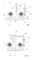
- first embodiment of a device 1 according to the invention for the plasma treatment of surfaces 2 has a first electrode 4, which is tubular and forms a process gas channel 3 in its interior.
- the first electrode 4 and its sheath coincide in this embodiment.
- a process gas having a low flow volume of, for example, 10 l / min and per electrode or per tip of the electrode is passed through the process gas channel 3.
- the process gas channel 3 ends in a flow direction, which is aligned opposite to a height direction H, in an outlet 5.
- Fig. 1 only one electrode tip 4a of the first electrode 4 is shown.
- the electrode tip 4a is made entirely of a conductive material, such as stainless steel, iron or copper alloys and connected to an AC voltage source 6.
- the AC voltage source 6 generates an alternating or pulsed high voltage of 18 kV to 20 kV at a frequency of 1 kHz to 250 kHz.
- the AC voltage source 6 is connected to grounded second electrodes 7 next to the first electrode 4.
- the second electrodes 7 are in Fig. 1 shown in section.
- the second electrodes 7 are rod-shaped and perpendicular to the plane of the paper Fig. 1 arranged in a longitudinal direction L.
- the device 1 in Fig. 1 12 illustrates only a single configuration of electrode tip 4a and two second electrodes 7 adjacent to electrode tip 4a.
- the entire device 1 has a plurality of electrode tips 4a arranged in series in the longitudinal direction L one behind the other.
- the spacing of the electrode tips 4a from one another is equidistant, and two rod-shaped second electrodes 7 are arranged parallel to the longitudinal direction L of the row of electrode tips 4a.
- Fig. 1 is shown on both sides of the row of electrode tips 4a each have a second rod-shaped electrode 7 in cross section.
- Both second electrodes 7 are connected to the AC voltage source 6, moreover, along a width direction B, which is parallel to the connecting line between the two second electrodes 7 and perpendicular to the longitudinal direction L and perpendicular to the height direction H, a plurality of aligned in the longitudinal direction L rows of electrode tips 4a be, so that the rows of electrode tips 4a are arranged parallel to each other and between two adjacent rows of electrode tips 4a each have a grounded rod-shaped second electrode 7 is provided.
- an electric field (not shown) forms, which is particularly strong at the outlet 5 of the electrode tip 4a. That is, at the outlet 5 of the electrode tip 4a, a particularly strong electric field is formed in operation.
- the field strength of the electric field is so strong that it transforms the effluent from the outlet 5 process gas stream into a plasma stream.
- a plasma is understood to mean a mixture of various constituents, which includes highly excited atomic states, highly excited molecular states, ions, electrons, but also unchanged constituents of the Process gas. Due to the formation of the field lines in the direction of a surface 2 of a substrate 11, the plasma already moves in a field-driven manner in the direction of the substrate 11.
- the electrode tip 4 a is formed as a tube through which a process gas can pass, so that the process gas, whose current direction is indicated by an arrow, flows through the electrode tip 4 a in the direction of the outlet 5 and the outlet 5 is directed in the direction of the surface 2 of the substrate 11 whereby the process gas flow in the tube, which is converted into a plasma when the outlet 5 passes, on the other hand additionally receives a component of movement in the direction of the surface 2 of the substrate 11.
- the speed of the process gas stream is only so great that forms a laminar flow in the electrode tip 4a, which remains at least substantially laminar even after leaving the outlet 5 of the electrode tip 4a and not swirled.
- the grounded second electrodes 7 are sheathed by a non-conductive dielectric 8.
- the dielectric 8 prevents sparkover between electrode tip 4a and grounded second electrodes 7 of the alternating or pulsed high voltage.
- the non-conductive dielectric 8 while the alternating high voltage is applied, an alternating displacement of the charge carriers is formed, but no current flow of free charge carriers takes place, so that a current flow generated by a flashover can be prevented.
- the device 1 in Fig. 1 also shows that the two grounded second electrodes 7 are arranged closer to an active region 9 of the device 1 than the outlet 5 of the electrode tip 4a.
- the field lines formed between the electrode tip 4a and the two grounded second electrodes 7 have a direction toward the effective region 9.
- the substrate 11 is shown with the surface 2 to be treated.
- the effective area 9 of the device 1 is the three-dimensional area in which the surface 2 of the substrate 11 is arranged and a desired and effective treatment can be subjected to a plasma current emerging from the electrode tip 4a.
- the process gas can be composed differently according to requirements, in particular it can be formed from a high proportion of nitrogen with small additions of noble gases and water vapor, wherein preferably 92.4 to 99.9 vol .-% nitrogen, 0.1 to 10 vol .-% noble gases and 0 to 2.5% by volume of water vapor are used to form the process gas.
- other process gases are also conceivable. Basically, all at room temperature (or slightly lower) to 200 ° C gaseous substances are zusetzbar, which may continue to have coating properties.
- the surface 2 is activated in the manner described above, whereby an improvement in the bond strength arises.
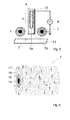
- Fig. 2 shows a second embodiment of the device 1 according to the invention for the plasma treatment of surfaces 2.
- the same reference numerals in the FIGS. 2 to 6 the same features as in Fig. 1 ,
- FIG. 1 is a schematic representation, which shows only one electrode tip 4a and two grounded second electrodes 7 in cross section, wherein the entire device 1 here also comprises a plurality of in series in the longitudinal direction L one behind the other perpendicular to the plane arranged electrode tips 4a, the have grounded second electrodes 7 running on both sides in the longitudinal direction L.
- the width direction B in turn, a plurality of rows of electrode tips 4a are provided.
- the electrode tip 4 a of the second embodiment comprises the first electrode 4, which is arranged centrally in the process gas channel 3, the first electrode 4 is concentrically surrounded by a sheath 12.
- the first electrode 4 and the sheath 12 together form the first electrode tip 4a.
- the electrode tip 4a as in the other embodiments, is circular in cross-section perpendicular to the height direction H.
- the process gas flows according to in the second embodiment Fig. 2 opposite to the height direction H along the process gas channel 3 and exits from the outlet 5 of the Electrode tip 4a.
- the field lines now do not form between the sheath 12 and the earthed second electrodes 7, but between the first electrode 4 provided as the core 14 in the electrode tip 4a and the two grounded second electrodes 7.
- the process gas exiting at a lower speed crosses the field lines of the field formed by the alternating high voltage between the first electrode 4 and the two second electrodes 7 and is converted into a plasma, which is field-driven on the one hand, and also by the kinetic energy absorbed from the process gas moved in the direction of the surface 2 of the substrate 11 and reaches the surface 2 as a plasma.
- the plasma activates the surface 2 of the substrate 11.
- the first electrode 4 protrudes along the height direction H a distance from the outlet 5 of the electrode tip 4a.
- FIG. 3 an electrode tip 4a is shown, which opposite to the electrode tip 4a of the second embodiment opposite to the height direction H ends a little way before the outlet 5 of the electrode tip 4a.
- the tip of the first electrode 4 a is thus arranged within the sheath 12 of the first electrode 4.
- the sheath 12 is brought closer to the active region 9 of the device 1, so that the distance between the surface 2 of the substrate 11 and the outlet 5 is lower than in the embodiment according to FIG Fig. 2 , As a result, a limited and even more targeted activation of a limited area of the surface 2 of the substrate 11 can take place.
- a fourth embodiment of the device 1 for the plasma treatment of surfaces 2 is shown, which in turn differs only in the design of the electrode tip 4a of the other embodiments.
- the electrode tip 4a has a tubular first electrode 4 and the casing 12 concentric with the tubular first electrode 4.
- the first electrode 4 is connected to the AC voltage source 6, and it is guided along the height direction H a little way beyond the outlet 5 of the casing 12 in the direction of the surface 2 of the substrate 11.
- the outlet 5 of the first electrode 4 has in the embodiment according to Fig. 4 two different outlet heights 5a, 5b, which are at different distances from the surface 2 and the active region 9.
- the one outlet level 5a is formed by an outlet of the tubular first electrode 4, and another outlet level 5b is formed through the outlet of the tubular shell 12 of FIG first electrode 4.
- the process gas channel 3 is provided, while between the outer wall of the first electrode 4 and the inner wall of the casing 12, an annular further process gas channel 13 is arranged.
- both the process gas from the process gas channel 3 and that from the further process gas channel 13 are converted into a plasma and are driven both field-driven and driven by the kinetic energy of the process gas itself on the surface. 2 of the substrate 11.
- the electrode tip 4a of Fig. 4 again modified to the effect that the casing 12 opposite to the height direction H is formed longer and closer to the surface 2 of the substrate 11 is brought closer.
- the first outlet height 5a of the tubular first electrode 4 is now more distant from the surface 2 of the substrate 11 than the second outlet height 5b of the sheath 12.
- the distance between the second outlet height 5b and the surface 2 is significantly smaller. This makes it possible to apply the plasma in a concentrated narrower area on the surface 2 of the substrate 11. Otherwise, the devices 1 correspond to the FIGS. 4 and 5 those of Fig. 1 ,
- FIG. 6 is another embodiment of the grounded second electrode 7 of FIGS. 1 to 5 shown in a perspective view.
- the second electrodes 7 have the conductive, rod-shaped core 14, which is connected to the grounded earth potential of the AC voltage source 6.
- the core 14 is completely encased by a gas-tight inner layer 15, and the inner layer 15 is encased by an annular gas channel 16 spaced from a porous outer layer 17.
- an annular gas channel 16 Through the annular gas channel 16, a gas stream is directed, which is indicated by an arrow.
- the purpose of the gas stream is to prevent or at least reduce deposits of the plasma on the second electrodes 7.
- molecules of the gas pass out of the grounded second electrodes 7.
- the exiting gas molecules prevent deposition of the process gas constituents which are reflected by the surface 2 of the substrate 11 or otherwise reach the second electrodes 7. Thereby, the life of the second electrodes 7 can be considerably increased.
Abstract
Vorrichtung zur Plasmabehandlung von Oberflächen (2) mit einer ersten Elektrode (4) und einer zweiten Elektrode (7) und einer Wechselspannungsquelle (6) zwischen erster (4) und zweiter Elektrode (7) und einem mindestens sich zwischen der ersten (4) und zweiten Elektrode (7) ausbildenden elektrischen Feld, einem vor der ersten Elektrode (4) angeordneten Wirkbereich (9), in dem die zu behandelnde Oberfläche (2) positionierbar ist,und die zweite Elektrode (7) ist dichter am Wirkbereich (9) angeordnet als die erste Elektrode (4), dadurch gekennzeichnet, dass wenigstens ein Prozessgaskanal (3) für wenigstens einen Prozessgasstrom mit wenigstens einem Auslass (5) an der ersten Elektrode (4) vorgesehen ist und der wenigstens eine Auslass (5) in Richtung des Wirkbereiches (9) weist und der wenigstens eine Prozessgasstrom das elektrische Feld trifft und das elektrische Feld den wenigstens einen Prozessgasstrom in einen Plasmastrom umwandelt und der Plasmastrom den Wirkbereich (9) trifft.Apparatus for the plasma treatment of surfaces (2) having a first electrode (4) and a second electrode (7) and an AC voltage source (6) between the first (4) and second electrodes (7) and at least one between the first (4) and second electrode (7) forming the electric field, one in front of the first electrode (4) arranged effective region (9) in which the surface to be treated (2) is positionable, and the second electrode (7) is arranged closer to the effective region (9) as the first electrode (4), characterized in that at least one process gas channel (3) is provided for at least one process gas stream with at least one outlet (5) on the first electrode (4) and the at least one outlet (5) in the direction of the effective region (9) and the at least one process gas stream meets the electric field and the electric field converts the at least one process gas stream into a plasma stream and the plasma stream strikes the active region (9).
Description
Die Erfindung betrifft eine Vorrichtung zur Plasmabehandlung von Oberflächen mit einer ersten Elektrode und einer zweiten Elektrode und einer Wechselspannungsquelle zwischen erster und zweiter Elektrode und einem sich zwischen der ersten Elektrode und der zweiten Elektrode ausbildenden elektrischen Feld und mit einem vor der ersten Elektrode angeordneten Wirkbereich, in dem die zu behandelnde Oberfläche positionierbar ist, wobei die zweite Elektrode dichter am Wirkbereich angeordnet ist als die erste Elektrode.The invention relates to a device for the plasma treatment of surfaces having a first electrode and a second electrode and an alternating voltage source between the first and second electrodes and an electric field forming between the first electrode and the second electrode and having an effective region arranged in front of the first electrode in which the surface to be treated can be positioned, wherein the second electrode is arranged closer to the effective region than the first electrode.
Die Erfindung betrifft auch ein Verfahren zur Behandlung von Oberflächen mit Plasma, indem zwischen einer ersten Elektrode und einer zweiten Elektrode eine Wechselspannung angelegt wird, zwischen den beiden Elektroden ein elektrisches Wechselfeld erzeugt wird, vor der ersten Elektrode eine zu behandelnde Oberfläche positioniert wird und die zweite Elektrode dichter an der Oberfläche angeordnet wird als die erste Elektrode.The invention also relates to a method for treating surfaces with plasma by applying an alternating voltage between a first electrode and a second electrode, generating an alternating electric field between the two electrodes, positioning a surface to be treated in front of the first electrode and the second Electrode is placed closer to the surface than the first electrode.
Grundsätzlich besteht beim Aufeinanderkleben von Oberflächen mittels Klebemassen das Problem, diese dauerhaft und fest auf die Oberfläche des Substrates aufzubringen. Dafür ist eine besonders hohe Adhäsion der Haftklebemasse an der Oberfläche notwendig. Als Adhäsion wird üblicherweise der physikalische Effekt bezeichnet, der den Zusammenhalt zweier miteinander in Kontakt gebrachter Phasen an ihrer Grenzfläche aufgrund dort auftretender intermolekularer Wechselwirkungen beschreibt. Die Adhäsion bestimmt somit das Anhaften der Klebemasse an der Substratoberfläche, die als Anfassklebrigkeit (dem sogenannten "Tack") und als Klebkraft bestimmbar ist. Um die Adhäsion einer Klebemasse gezielt zu beeinflussen, werden der Klebemasse häufig Weichmacher und/oder klebkraftsteigernde Harze (sogenannte "Tackifier") zugesetzt.Basically, the bonding together of surfaces by means of adhesives has the problem of applying them permanently and firmly to the surface of the substrate. This requires a particularly high adhesion of the PSA to the surface. Adhesion is usually referred to as the physical effect which describes the cohesion of two phases brought into contact at their interface on the basis of intermolecular interactions occurring there. The adhesion thus determines the adhesion of the adhesive to the substrate surface, which can be determined as initial tack (the so-called "tack") and as bond strength. To the adhesion of an adhesive targeted to influence the adhesive often plasticizer and / or tackifying resins (so-called "tackifier") are added.
Eine einfache Definition der Adhäsion kann "die Wechselwirkungsenergie pro Einheitsfläche" [in mN/m] sein, wobei diese aufgrund experimenteller Einschränkungen wie Unkenntnis der wahren Kontaktflächen nicht messbar ist. Weiterhin wird oft die Oberflächenenergie (OFE) beschrieben mit "polaren" und "unpolaren" Komponenten. Dieses vereinfachende Modell hat sich in der Praxis durchgesetzt. Gemessen werden diese Energie und ihre Komponenten oft mittels Messung der statischen Kontaktwinkel unterschiedlicher Testflüssigkeiten. Den Oberflächenspannungen dieser Flüssigkeiten werden polare und unpolare Anteile zugeordnet. Aus den beobachteten Kontaktwinkeln der Tropfen auf der Prüfoberfläche werden die polaren und unpolaren Anteile der Oberflächenenergie der Prüfoberfläche ermittelt. Dies kann zum Beispiel nach dem OWKR-Modell erfolgen. Eine industriell übliche alternative Methode ist die Bestimmung mittels Testtinten nach DIN ISO 8296.A simple definition of adhesion may be "the interaction energy per unit area" [in mN / m], which is not measurable due to experimental constraints such as ignorance of true contact areas. Furthermore, surface energy (OFE) is often described as having "polar" and "non-polar" components. This simplistic model has prevailed in practice. This energy and its components are often measured by measuring the static contact angles of different test liquids. The surface tensions of these liquids are assigned polar and non-polar components. From the observed contact angles of the droplets on the test surface, the polar and nonpolar portions of the surface energy of the test surface are determined. This can be done, for example, according to the OWKR model. An industrially customary alternative method is the determination by means of test inks according to DIN ISO 8296.
Im Kontext solcher Diskussionen werden oft die Begriffe "polar" und "hochenergetisch" gleichgesetzt, ebenso die Begriffe "unpolar" und "niederenergetisch". Dahinter steht die Erkenntnis, dass polare Dipolkräfte vergleichsweise stark sind gegenüber sogenannten "dispersen" oder "unpolaren" Wechselwirkungen, die ohne Beteiligung permanenter molekularer Dipole aufbaut werden. Die Grundlage dieses Modells der Grenzflächenenergie und Grenzflächenwechselwirkungen ist die Vorstellung, dass polare Komponenten nur mit polaren wechselwirken und unpolare nur mit unpolaren.In the context of such discussions, the terms "polar" and "high energy" are often equated, as are the terms "nonpolar" and "low energy". Behind this is the realization that polar dipole forces are comparatively strong compared to so-called "disperse" or "nonpolar" interactions, which are built up without the involvement of permanent molecular dipoles. The basis of this model of interfacial energy and interfacial interactions is the notion that polar components interact only with polar and nonpolar with only non-polar ones.
Jedoch kann eine Oberfläche auch kleine oder mittlere polare Anteile an der Oberflächenenergie aufweisen, ohne dass die Oberflächenenergie "hoch" ist. Ein Richtwert kann sein, dass, sobald der polare Anteil der OFE größer ist als 3 mN/m, die Oberfläche im Sinne dieser Erfindung als "polar" zu bezeichnen ist. Dies entspricht in etwa der praktischen unteren Nachweisgrenze.However, a surface may also have small or medium polar parts of the surface energy without the surface energy being "high". A guideline may be that, as soon as the polar fraction of the OFE is greater than 3 mN / m, the surface for the purposes of this invention is to be termed "polar". This roughly corresponds to the practical lower detection limit.
Grundsätzlich gibt es keine harten Grenzen für Begriffe wie hoch- und niederenergetisch. Für den Zweck der Diskussion wird die Grenze bei 38 mN/m beziehungsweise 38 dyn/cm (bei Raumtemperatur) gesetzt. Dies ist ein Wert, oberhalb dessen beispielsweise die Bedruckbarkeit einer Oberfläche meist hinreichend ist. Zum Vergleich kann man die Oberflächenspannung (=Oberflächenenergie) von reinem Wasser betrachten; diese liegt bei ca. 72 mN/m (unter anderem temperaturabhängig).Basically, there are no hard limits for terms such as high and low energy. For the purpose of the discussion, the limit is set at 38 mN / m and 38 dyn / cm (at room temperature, respectively). This is a value above which, for example, the printability of a surface is usually sufficient. For comparison, you can the Consider surface tension (= surface energy) of pure water; this is around 72 mN / m (including temperature-dependent).
Insbesondere auf niederenergetischen Substraten wie PE, PP oder EPDM, aber auch vielen Lacken gibt es große Probleme bei der Erreichung zufriedenstellender Adhäsion, sowohl bei Verwendung von Haftklebemassen als auch anderen Klebstoffen oder Beschichtungen.In particular, on low-energy substrates such as PE, PP or EPDM, but also many paints there are great problems in achieving satisfactory adhesion, both when using PSAs and other adhesives or coatings.
Die physikalische Vorbehandlung von Untergründen (zum Beispiel durch Flamme, Corona, Plasma) zur Verbesserung von Verklebungsfestigkeiten ist vor allem bei flüssigen Reaktivklebstoffen üblich. Eine Aufgabe der physikalischen Vorbehandlung kann dabei auch eine Reinigung des Untergrunds sein, beispielsweise von Ölen, oder ein Aufrauen zur Vergrößerung der effektiven Fläche.The physical pretreatment of substrates (for example, by flame, corona, plasma) to improve bonding strengths is common especially in liquid reactive adhesives. An object of the physical pretreatment can also be a cleaning of the substrate, for example of oils, or roughening to increase the effective area.
Bei einer physikalischen Vorbehandlung spricht man meist von einer "Aktivierung" der Oberfläche. Dies impliziert meist eine unspezifische Wechselwirkung im Gegensatz beispielsweise zu einer chemischen Reaktion nach dem Schlüssel-Schloss-Prinzip. Eine Aktivierung impliziert meistens eine Verbesserung von Benetzbarkeit, Bedruckbarkeit oder Verankerung einer Beschichtung.In a physical pretreatment one usually speaks of an "activation" of the surface. This usually implies an unspecific interaction in contrast, for example, to a chemical reaction according to the key-lock principle. Activation usually implies an improvement in wettability, printability or anchoring of a coating.
Bei Selbstklebebändern ist ein Auftragen eines Haftvermittlers auf den Untergrund üblich. Dies ist aber oft ein fehleranfälliger, aufwändiger, manueller Schritt.For self-adhesive tapes, it is common to apply a primer to the substrate. However, this is often an error-prone, time-consuming, manual step.
Der Erfolg bei der Verbesserung der Adhäsion von Haftklebemassen durch physikalische Vorbehandlung des Untergrunds (Flamme, Corona, Plasma) ist nicht universell, da unpolare Klebemassen wie zum Beispiel Natur- oder Synthesekautschuk typischerweise nicht davon profitieren.The success in improving the adhesion of PSAs by physical pretreatment of the substrate (flame, corona, plasma) is not universal because non-polar adhesives such as natural or synthetic rubber typically do not benefit.
Eine Coronabehandlung ist als eine durch hohe Wechselspannung zwischen zwei Elektroden erzeugte Oberflächenbehandlung mit filamentären Entladungen definiert, wobei die diskreten Entladungskanäle auf die zu behandelnde Oberfläche treffen, siehe dazu auch
Insbesondere wird in industriellen Anwendungen meist unter dem Begriff "Corona" eine "dielektrische Barriereentladung" (engl. dielectric barrier discharge, DBD) verstanden. Dabei besteht mindestens eine der Elektroden aus einem Dielektrikum, also einem Isolator, oder ist mit einem solchen beschichtet oder überzogen. Das Substrat kann hierbei auch als Dielektrikum fungieren.In particular, in industrial applications, the term "corona" is usually understood as meaning a "dielectric barrier discharge" (DBD). At least one of the electrodes consists of a dielectric, ie an insulator, or is coated or coated with such a dielectric. The substrate can also act as a dielectric in this case.
Die Behandlungsintensität einer Coronabehandlung wird als "Dosis" in [Wmin/m2] angegeben, mit der Dosis D=P/b*v, mit P=elektrischer Leistung [W], b=Elektrodenbreite [m], und v=Bahngeschwindigkeit [m/min].The treatment intensity of a corona treatment is given as "dose" in [Wmin / m 2 ], with the dose D = P / b * v, with P = electrical power [W], b = electrode width [m], and v = web speed [ m / min].
Fast immer wird das Substrat im Entladungsraum zwischen einer Elektrode und einer Gegenelektrode platziert oder hindurchgeführt, was als "direkte" physikalische Behandlung definiert ist. Bahnförmige Substrate werden dabei typischerweise zwischen einer Elektrode und einer geerdeten Walze hindurchgeführt. Manchmal wird noch der Begriff einer "ausgeblasenen Corona" beziehungsweise "einseitigen Corona" verwendet. Dies ist nicht vergleichbar mit einer direkten physikalischen Behandlung, da hier nach dem Stand der Technik hohe Gasströme benötigt werden, um das Plasma als Effluent in Richtung des Substrates aus der Elektrodenanordnung auszutreiben oder so dass unregelmäßige Entladungsfilamente zusammen mit einem Prozessgas "ausgeblasen" werden und keine stabile, wohldefinierte, effiziente Behandlung möglich ist.Almost always, the substrate is placed or passed in the discharge space between an electrode and a counter electrode, which is defined as a "direct" physical treatment. Web-shaped substrates are typically passed between an electrode and a grounded roller. Sometimes the term "blown out corona" or "unilateral corona" is used. This is not comparable to a direct physical treatment, since in the prior art high gas flows are required here in order to expel the plasma as effluent in the direction of the substrate from the electrode arrangement or so that irregular discharge filaments are "blown out" together with a process gas and none stable, well-defined, efficient treatment is possible.
Aus der
Eine gleichmäßigere intensive Coronabehandlung von Materialien verschiedener Art, Form und Dicke zu ermöglichen, besteht darin, den Coronaeffekt auf der Oberfläche des zu behandelnden Materials völlig zu vermeiden, indem gemäß der
Das Plasmagerät der
Unter dem Plasma wird hier ein Atmosphärendruckplasma verstanden, das ein elektrisch aktiviertes homogenes reaktives Gas ist, das sich nicht im thermischen Equilibrium befindet, mit einem Druck nahe am (+/- 0,05 bar) oder bei Atmosphärendruck beziehungsweise Umgebungsdruck im Wirkbereich. Durch die elektrischen Entladungen und durch Ionisierungsprozesse im elektrischen Feld wird das Gas aktiviert, und es werden hochangeregte Zustände in den Gasbestandteilen erzeugt. Das verwendete Gas und die Gasmischung werden als Prozessgas bezeichnet. Grundsätzlich können dem Prozessgas auch gasförmige Stoffe wie Siloxan, Acrylsäuren oder Lösungsmittel oder andere Bestandteile beigemischt werden. Bestandteile des Atmosphärendruckplasmas können hochangeregte atomare Zustände, hochangeregte molekulare Zustände, Ionen, Elektronen, unveränderte Bestandteile des Prozessgases sein. Das Atmosphärendruckplasma wird nicht in einem Vakuum erzeugt, sondern üblicherweise in Luftumgebung. Das bedeutet, dass das ausströmende Plasma, wenn das Prozessgas nicht selbst schon Luft ist, zumindest Bestandteile der umgebenden Luft enthält oder davon umgeben wird.To allow a more uniform intensive corona treatment of materials of various types, shapes and thicknesses is to completely avoid the corona effect on the surface of the material to be treated, according to the
The plasma device of
By plasma is meant here an atmospheric pressure plasma, which is an electrically activated homogeneous reactive gas that is not in thermal equilibrium, with a pressure close to (+/- 0.05 bar) or at atmospheric pressure or ambient pressure in the effective range. The electrical discharges and ionization processes in the electric field activate the gas and generate highly excited states in the gas constituents. The gas used and the gas mixture are called process gas. In principle, gaseous substances such as siloxane, acrylic acids or solvents or other constituents can also be added to the process gas. Components of the atmospheric pressure plasma can be highly excited atomic states, highly excited molecular states, ions, electrons, unchanged constituents of the process gas. The atmospheric pressure plasma is not generated in a vacuum but usually in an air environment. This means that, if the process gas itself is not already air, the outflowing plasma at least contains or is surrounded by constituents of the surrounding air.
Bei einer Coronaentladung nach obiger Definition bilden sich durch die angelegte hohe Spannung filamentäre Entladungskanäle mit Elektronen und Ionen. Insbesondere die leichten Elektronen treffen mit hoher Geschwindigkeit auf die Oberfläche mit Energien, die ausreichen, um die meisten Molekülbindungen aufzubrechen. Die aufgebrochenen Bindungsstellen reagieren dann mit Bestandteilen der Luft oder des Prozessgases weiter. Ein entscheidender Effekt ist die Bildung kurzkettiger Abbauprodukte durch Elektronenbeschuss. Bei Behandlungen höherer Intensität tritt auch ein signifikanter Materialabtrag ein.In a corona discharge as defined above, filamentary discharge channels with electrons and ions form due to the applied high voltage. In particular, the light electrons hit the surface at high speed with energies that sufficient to break most of the molecular bonds. The broken bond sites then react with constituents of the air or process gas. A decisive effect is the formation of short-chain degradation products by electron bombardment. For higher intensity treatments, significant material removal also occurs.
Durch die Reaktion eines Plasmas mit der Substratoberfläche werden verstärkt die Plasmabestandteile direkt "eingebaut". Alternativ können auf der Oberfläche ein angeregter Zustand oder eine offene Bindungsstelle und Radikale erzeugt werden, die dann sekundär weiterreagieren, zum Beispiel mit Luftsauerstoff aus der Umgebungsluft. Bei manchen Gasen wie Edelgasen ist keine chemische Bindung der Prozessgasatome oder -moleküle an das Substrat zu erwarten. Hier findet die Aktivierung des Substrats ausschließlich über Sekundärreaktionen statt.Due to the reaction of a plasma with the substrate surface, the plasma constituents are increasingly directly "incorporated". Alternatively, an excited state or an open binding site and radicals can be generated on the surface, which then further react secondarily, for example with atmospheric oxygen from the ambient air. For some gases, such as noble gases, no chemical bonding of the process gas atoms or molecules to the substrate is to be expected. Here the activation of the substrate takes place exclusively via secondary reactions.
Bei einer indirekten Plasmabehandlung sind freie Elektronen möglicherweise vorhanden, da die Behandlung außerhalb des erzeugenden elektrischen Feldes stattfindet, hängt aber von der Art der Plasmaausbreitung ab.In an indirect plasma treatment, free electrons may be present because the treatment takes place outside the generating electric field, but depends on the type of plasma propagation.
Es ist Aufgabe der vorliegenden Erfindung, eine Vorrichtung der eingangs genannten Art zur Verfügung zu stellen, die eine indirekte Coronabehandlung einer Oberfläche ermöglicht bei keiner oder einer sehr geringen Strömungsgeschwindigkeit.It is an object of the present invention to provide a device of the type mentioned above, which allows an indirect corona treatment of a surface at no or a very low flow rate.
Es ist weiterhin Aufgabe der Erfindung, ein Verfahren der eingangs genannten Art zur Verfügung zu stellen, das die genannten Nachteile wie hohe Strömungsgeschwindigkeit und damit hoher Gasverbrauch sowie eine Schädigung der Rückseite des Substrates ebenfalls vermeidet.It is a further object of the invention to provide a method of the type mentioned above, which also avoids the disadvantages mentioned such as high flow rate and thus high gas consumption and damage to the back of the substrate.
Hinsichtlich der Vorrichtung wird die Aufgabe durch eine eingangs genannte Vorrichtung mit den kennzeichnenden Merkmalen des Anspruchs 1 gelöst.With regard to the device, the object is achieved by an aforementioned device with the characterizing features of
Die Vorrichtung ist gegenüber der
Gegenüber der direkten Coronabehandlung der
Im erfinderischen Sinn dient das Prozessgas lediglich dazu, besondere Spezies erzeugen zu können.
Vorzugsweise ist die erste Elektrode stabförmig ausgebildet und im Inneren des Prozessgaskanals angeordnet. Bei dieser Ausführungsform sind günstigerweise genau ein Prozessgaskanal und genau ein Prozessgasstrom vorgesehen. Dadurch ist es möglich, dass das Prozessgas die erste Elektrode umlaufend umströmt und zu einem besonders hohen Anteil in Plasma umgewandelt wird. Das Prozessgas dient eben nicht dazu, das Plasma aus der Plasmaquelle in Richtung Substrat auszutreiben.In the inventive sense, the process gas only serves to be able to produce special species.
Preferably, the first electrode is rod-shaped and arranged in the interior of the process gas channel. In this embodiment, exactly one process gas channel and exactly one process gas stream are favorably provided. As a result, it is possible for the process gas to flow around the first electrode all around and be converted into a particularly high proportion in plasma. The process gas does not serve to expel the plasma from the plasma source in the direction of the substrate.
In einer weiteren Ausführungsform der Erfindung ist die erste Elektrode rohrförmig ausgebildet und umschließt einen weiteren Prozessgaskanal. Die rohrförmige Elektrode ist vorzugsweise weiterhin zentral in dem Prozessgaskanal angeordnet. Der Prozessgaskanal und der weitere Prozessgaskanal sind voneinander getrennt und parallel zueinander ausgerichtet. Dabei ist der weitere Prozessgaskanal im Inneren der rohrförmigen Elektrode vorgesehen, und die Elektrode wird außen von dem Prozessgaskanal ummantelt. Der Prozessgaskanal ist von einer Ummantelung umgeben und durch sie ausgebildet. Vorzugsweise ragt die erste Elektrode dichter an den Wirkbereich heran als die Ummantelung. Die erste Elektrode steht dabei entlang einer Höhenrichtung in Richtung des Wirkbereiches über die Ummantelung hinaus ab.In a further embodiment of the invention, the first electrode is tubular and encloses a further process gas channel. The tubular electrode is preferably further centrally located in the process gas channel. The process gas channel and the further process gas channel are separated from each other and aligned parallel to each other. In this case, the further process gas channel is provided in the interior of the tubular electrode, and the electrode is encased on the outside by the process gas channel. The process gas channel is surrounded by a shell and formed by them. Preferably, the first electrode protrudes closer to the effective area than the sheath. The first electrode projects along a height direction in the direction of the effective range beyond the sheath.
Es ist jedoch auch möglich, dass die Elektrode in einer anderen Ausführungsform der Erfindung in Höhenrichtung kürzer als die Ummantelung ausgebildet ist, also die Ummantelung dichter an den Wirkbereich heranragt als die erste Elektrode. Die unterschiedliche Länge der Elektrode gegenüber der Ummantelung kann sowohl bei einer stabförmigen als auch rohrförmigen ersten Elektrode gewählt werden.However, it is also possible that the electrode is formed in another embodiment of the invention in the height direction shorter than the sheath, so the sheath denser denser at the effective range than the first electrode. The different length of the electrode relative to the sheath can be selected both in a rod-shaped and tubular first electrode.
Durch die unterschiedliche Länge und Anzahl der Prozessgaskanäle ist es möglich, je nach Bedarf eine individuell zugeschnittene Vorrichtung zur Behandlung einer Oberfläche zur Verfügung zu stellen.Due to the different length and number of process gas channels, it is possible to provide an individually tailored device for the treatment of a surface as needed.
Bei beschichtenden Plasmasystemen hat sich gezeigt, dass das auf die Oberfläche des Substrates treffende vom Plasma aktivierte Gas, nachdem es dort eine Abscheidung vorgenommen hat, auch wieder zurück in Richtung Elektroden verwirbelt werden kann und dort ebenfalls im Laufe der Zeit eine Beschichtung ausbildet. Um die Gefahr einer Beschichtung zu verringern oder sogar ganz auszuräumen, ist die zweite Elektrode günstigerweise stabförmig ausgebildet und von einer gasdichten Innenschicht umgeben, und zwischen der gasdichten Innenschicht und einer gasdurchlässigen dielektrischen Außenschicht ist ein Gaskanal vorgesehen. Der Gaskanal ist unabhängig vom Prozessgaskanal. Die zweite Elektrode ist vorzugsweise die geerdete Elektrode. Sie ist von einer gasdichten Innenschicht umgeben, so dass das Gas zwischen der gasdichten Innenschicht und der die gasdichte Innenschicht wiederum ummantelnden gasdurchlässigen dielektrischen Außenschicht nicht zur Elektrode gelangen kann, sondern nur durch die gasdurchlässige dielektrische Außenschicht von der zweiten Elektrode wegströmt. Durch diesen Strom weg von der zweiten Elektrode wird einem Ablagern des reflektierten Plasmas entgegengewirkt.In the case of coating plasma systems, it has been found that the gas activated by the plasma on the surface of the substrate, after it has made a deposition there, can also be swirled back again in the direction of the electrodes and likewise forms a coating there over time. In order to reduce or even completely eliminate the risk of a coating, the second electrode is favorably rod-shaped and surrounded by a gas-tight inner layer, and a gas channel is provided between the gas-tight inner layer and a gas-permeable outer dielectric layer. The gas channel is independent of the process gas channel. The second electrode is preferably the grounded electrode. It is surrounded by a gas-tight inner layer, so that the gas between the gas-tight inner layer and the gas-tight inner layer again ummantelnden gas-permeable dielectric outer layer can not get to the electrode, but flows away only through the gas-permeable dielectric outer layer of the second electrode. By this current away from the second electrode, a deposition of the reflected plasma is counteracted.
Besonders bevorzugt weist die Vorrichtung nicht nur eine einzelne erste und genau eine oder genau zwei zweite Elektroden auf, sondern eine Vielzahl an ersten Elektroden in mehreren, jeweils in einer Längsrichtung ausgerichteten Reihen, die hintereinander angeordnet sind und mehrere stabförmige zweite Elektroden, die jeweils entlang einer der Reihen erster Elektroden in Längsrichtung verlaufen. Es ist in dieser Ausführungsform der Erfindung ein ganzes Gitter an ersten Elektroden vorgesehen, wodurch eine großflächige Behandlung der Oberfläche ermöglicht wird.Particularly preferably, the device not only has a single first and exactly one or exactly two second electrodes, but a plurality of first electrodes in a plurality, each aligned in a longitudinal direction rows, which are arranged one behind the other and a plurality of rod-shaped second electrodes, each along one the rows of first electrodes extend in the longitudinal direction. It is in this embodiment of Invention, a whole grid provided on the first electrode, whereby a large-area treatment of the surface is made possible.
Hinsichtlich des Verfahrens wird die Aufgabe durch ein eingangs genanntes Verfahren mit den kennzeichnenden Merkmalen des Anspruchs 9 gelöst.With regard to the method, the object is achieved by an aforementioned method with the characterizing features of claim 9.
Das Verfahren eignet sich insbesondere zur Durchführung mit einer oder mehreren der oben genannten Vorrichtungen. Bei dem eingangs genannten Verfahren wird wenigstens ein Prozessgasstrom durch wenigstens einen Prozessgaskanal geführt. Der wenigstens eine Prozessgaskanal weist wenigstens einen Auslass auf. Der wenigstens eine Prozessgasstrom verlässt den wenigstens einen Auslass in Richtung des Wirkbereiches, und der wenigstens eine Prozessgasstrom trifft auf das elektrische Feld, und das elektrische Feld wandelt den wenigstens einen Prozessgasstrom in ein Plasmaraum, und das Plasma trifft den Wirkbereich. In dem Wirkbereich wird vorzugsweise die Oberfläche des Substrates angeordnet, und der Plasmastrom trifft auf diese Oberfläche und aktiviert die Oberfläche, indem er die Oberfläche beispielsweise aktiviert oder andere bekannte physikalische Reaktionen an der Oberfläche durchführt, die die Haftkraft eines Haftklebers auf ihr vergrößern. Diese Arten der Aktivierungen sind grundsätzlich aus
Günstigerweise umströmt der Prozessgasstrom die erste stabförmig ausgebildete Elektrode außen; es ist jedoch auch denkbar, dass ein weiterer Prozessgasstrom durch das Innere der röhrenförmig ausgebildeten Elektrode strömt.Conveniently, the process gas stream flows around the first rod-shaped electrode outside; However, it is also conceivable that a further process gas stream flows through the interior of the tubular electrode.
In einer Ausführungsform der Erfindung endet der weitere Prozessgasstrom innerhalb der Ummantelung und geht in den Prozessgasstrom über, während in einer anderen Ausführungsform des erfindungsgemäßen Verfahrens die stabförmige Elektrode länger ausgebildet ist als die Ummantelung der Elektrode, so dass der weitere Prozessgasstrom außerhalb der Ummantelung endet und sich erst zu einem späteren Zeitpunkt und in einer geringeren Entfernung zur Oberfläche des Substrates mit dem Prozessgasstrom vermengt.In one embodiment of the invention, the further process gas stream ends within the casing and passes into the process gas stream, while in another embodiment of the method according to the invention, the rod-shaped electrode is formed longer than the sheath of the electrode, so that the further process gas stream ends outside the casing and only mixed with the process gas stream at a later time and at a smaller distance to the surface of the substrate.
Günstigerweise ist die zweite Elektrode in einer der oben genannten Ausführungsformen ausgestaltet, und ein Gasstrom strömt entlang der zweiten Elektrode und durch eine gasdurchlässige dielektrische Außenschicht hindurch nach außen, so dass Ablagerungen des Plasmas an der zweiten Elektrode verhindert werden können.Conveniently, the second electrode is configured in one of the above-mentioned embodiments, and a gas flow flows along the second electrode and through one gas-permeable outer dielectric layer to the outside, so that deposits of the plasma can be prevented at the second electrode.
Die Erfindung wird anhand mehrerer Ausführungsbeispiele in sechs Figuren beschrieben, dabei zeigen:
-
Fig. 1 eine erfindungsgemäße Vorrichtung zur Plasmabehandlung von Oberflächen in einer ersten Ausführungsform, -
Fig. 2 eine zweite Ausführungsform der Vorrichtung zur Plasmabehandlung von Oberflächen, -
Fig. 3 eine dritte Ausführungsform der Vorrichtung zur Plasmabehandlung von Oberflächen, -
Fig. 4 eine vierte Ausführungsform der Vorrichtung zur Plasmabehandlung von Oberflächen, -
Fig. 5 eine fünfte Ausführungsform der Vorrichtung zur Plasmabehandlung von Oberflächen -
Fig. 6 eine perspektivische Ansicht einer geerdeten Elektrode einer der Ausführungsformen inden Figuren 1 .bis 5
-
Fig. 1 a device according to the invention for the plasma treatment of surfaces in a first embodiment, -
Fig. 2 A second embodiment of the device for the plasma treatment of surfaces, -
Fig. 3 a third embodiment of the device for the plasma treatment of surfaces, -
Fig. 4 A fourth embodiment of the device for the plasma treatment of surfaces, -
Fig. 5 A fifth embodiment of the device for the plasma treatment of surfaces -
Fig. 6 a perspective view of a grounded electrode of one of the embodiments in theFIGS. 1 to 5 ,
Die in
In
Die zweiten Elektroden 7 sind stabförmig ausgeformt und senkrecht zur Papierebene der
An den offenen Enden der röhrenförmigen Elektrodenspitze 4a bildet sich ein elektrisches Feld bei angelegter Wechselspannung aus. Allerdings bilden sich zwischen der Außenwandung der Elektrodenspitze 4a und den beiden zweiten geerdeten Elektroden 7 ein (nicht eingezeichnetes) elektrisches Feld aus, das am Auslass 5 der Elektrodenspitze 4a besonders stark ist. Das heißt, am Auslass 5 der Elektrodenspitze 4a ist ein besonders starkes elektrisches Feld in Betrieb ausgebildet. Die Feldstärke des elektrischen Feldes ist so stark, dass es den aus dem Auslass 5 austretenden Prozessgasstrom in einen Plasmastrom verwandelt. Unter einem Plasma wird hier ein Gemenge aus verschiedenen Bestandteilen verstanden, das hochangeregte atomare Zustände umfasst, hochangeregte molekulare Zustände, Ionen, Elektronen, aber auch unveränderte Bestandteile des Prozessgases. Aufgrund der Ausbildung der Feldlinien in Richtung einer Oberfläche 2 eines Substrats 11 bewegt sich das Plasma bereits feldgetrieben in Richtung des Substrates 11.At the open ends of the
Die Elektrodenspitze 4a ist jedoch als von einem Prozessgas durchströmbare Röhre ausgebildet, so dass das Prozessgas, dessen Stromrichtung durch einen Pfeil dargestellt ist, durch die Elektrodenspitze 4a in Richtung des Auslasses 5 strömt und der Auslass 5 in Richtung der Oberfläche 2 des Substrates 11 gerichtet ist, wodurch der Prozessgasstrom in der Röhre, der beim Durchtritt des Auslasses 5 in ein Plasma umgewandelt wird, zum anderen zusätzlich eine Bewegungskomponente in Richtung der Oberfläche 2 des Substrates 11 erhält.However, the
Die Geschwindigkeit des Prozessgasstromes ist nur so groß, dass sich in der Elektrodenspitze 4a eine laminare Strömung ausbildet, die auch nach Verlassen des Auslasses 5 der Elektrodenspitze 4a zumindest im Wesentlichen laminar bleibt und nicht verwirbelt.The speed of the process gas stream is only so great that forms a laminar flow in the
Die geerdeten zweiten Elektroden 7 sind von einem nicht leitenden Dielektrikum 8 ummantelt. Das Dielektrikum 8 verhindert einen Funkenüberschlag zwischen Elektrodenspitze 4a und geerdeten zweiten Elektroden 7 der alternierenden oder gepulsten Hochspannung. In dem nicht leitenden Dielektrikum 8 bildet sich, während die alternierende Hochspannung angelegt ist, eine alternierende Verschiebung der Ladungsträger aus, jedoch findet kein Stromfluss freier Ladungsträger statt, so dass ein durch einen Funkenüberschlag erzeugter Stromfluss unterbunden werden kann.The grounded
Die Vorrichtung 1 in
Der Wirkbereich 9 der Vorrichtung 1 ist der dreidimensionale Bereich, in dem die Oberfläche 2 des Substrates 11 angeordnet wird und einer gewünschten und effektiven Behandlung durch einen aus der Elektrodenspitze 4a austretenden Plasmastrom unterzogen werden kann.The effective area 9 of the
Das Prozessgas kann je nach Bedarf verschieden zusammengesetzt sein, insbesondere kann es aus einem hohen Anteil an Stickstoff mit geringen Zusätzen von Edelgasen und Wasserdampf gebildet werden, wobei vorzugsweise 92,4 bis 99,9 Vol.-% Stickstoff, 0,1 bis 10 Vol.- % Edelgase und 0 bis 2,5 Vol.- % Wasserdampf zur Ausbildung des Prozessgases herangezogen werden. Es sind jedoch auch andere Prozessgase denkbar. Grundsätzlich sind alle bei Raumtemperatur (oder etwas tiefer) bis 200 °C gasförmigen Stoffe zusetzbar, die weiterhin auch beschichtende Eigenschaften haben können.The process gas can be composed differently according to requirements, in particular it can be formed from a high proportion of nitrogen with small additions of noble gases and water vapor, wherein preferably 92.4 to 99.9 vol .-% nitrogen, 0.1 to 10 vol .-% noble gases and 0 to 2.5% by volume of water vapor are used to form the process gas. However, other process gases are also conceivable. Basically, all at room temperature (or slightly lower) to 200 ° C gaseous substances are zusetzbar, which may continue to have coating properties.
Durch das Plasma wird die Oberfläche 2 in der eingangs beschriebenen Weise aktiviert, wodurch eine Verbesserung der Verklebungsfestigkeit entsteht.By the plasma, the
Auch hier handelt es sich um eine schematische Darstellung, die lediglich eine Elektrodenspitze 4a und zwei geerdete zweite Elektroden 7 im Querschnitt zeigt, wobei die gesamte Vorrichtung 1 auch hier eine Mehrzahl von in Reihe in Längsrichtung L hintereinander senkrecht zur Zeichenebene angeordneten Elektrodenspitzen 4a umfasst, die an beiden Seiten in Längsrichtung L verlaufende geerdete zweite Elektroden 7 aufweisen. In Breitenrichtung B sind wiederum mehrere Reihen von Elektrodenspitzen 4a vorgesehen.Here, too, is a schematic representation, which shows only one
Die Elektrodenspitze 4a der zweiten Ausführungsform umfasst die erste Elektrode 4, die zentral in dem Prozessgaskanal 3 angeordnet ist, die erste Elektrode 4 ist konzentrisch von einer Ummantelung 12 umgeben. Die erste Elektrode 4 und die Ummantelung 12 bilden zusammen die erste Elektrodenspitze 4a aus. Die Elektrodenspitze 4a ist wie auch in den anderen Ausführungsformen im Querschnitt senkrecht zur Höhenrichtung H kreisförmig ausgebildet.The
Das Prozessgas strömt in der zweiten Ausführungsform gemäß
Das mit geringerer Geschwindigkeit austretende Prozessgas kreuzt die Feldlinien des durch die alternierende Hochspannung gebildeten Feldes zwischen erster Elektrode 4 und den beiden zweiten Elektroden 7 und wird in ein Plasma umgewandelt, das sich zum einen feldgetrieben, zum anderen auch durch die aus dem Prozessgas aufgenommene kinetische Energie in Richtung der Oberfläche 2 des Substrates 11 bewegt und die Oberfläche 2 als Plasma erreicht. Das Plasma aktiviert die Oberfläche 2 des Substrates 11. Die erste Elektrode 4 steht entlang der Höhenrichtung H ein Stück weit aus dem Auslass 5 der Elektrodenspitze 4a heraus ab.The process gas exiting at a lower speed crosses the field lines of the field formed by the alternating high voltage between the
In
In der
In der in
In der
- 11
- Vorrichtungcontraption
- 22
- Oberflächesurface
- 33
- ProzessgaskanalProcess gas channel
- 44
- erste Elektrodefirst electrode
- 4a4a
- Elektrodenspitzeelectrode tip
- 55
- Auslassoutlet
- 5a5a
- Auslasshöheoutlet height
- 5b5b
- Auslasshöheoutlet height
- 66
- WechselspannungsquelleAC voltage source
- 77
- zweite Elektrodesecond electrode
- 88th
- Dielektrikumdielectric
- 99
- Wirkbereicheffective range
- 1111
- Substratsubstratum
- 1212
- Ummantelungjacket
- 1313
- weiterer Prozessgaskanalanother process gas channel
- 1414
- Seelesoul
- 1515
- gasdichte Innenschichtgastight inner layer
- 1616
- ringförmiger Gaskanalannular gas channel
- 1717
- poröse Außenschichtporous outer layer
- BB
- Breitenrichtungwidth direction
- HH
- Höhenrichtungheight direction
- LL
- Längsrichtunglongitudinal direction
Claims (13)
einer ersten Elektrode (4) und
einer zweiten Elektrode (7) und einer Wechselspannungsquelle (6) zwischen erster (4) und zweiter Elektrode (7) und einem mindestens sich zwischen der ersten (4) und zweiten Elektrode (7) ausbildenden elektrischen Feld,
einem vor der ersten Elektrode (4) angeordneten Wirkbereich (9), in dem die zu behandelnde Oberfläche (2) positionierbar ist,
und die zweite Elektrode (7) ist dichter am Wirkbereich (9) angeordnet als die erste Elektrode (4),
dadurch gekennzeichnet, dass
wenigstens ein Prozessgaskanal (3) für wenigstens einen Prozessgasstrom mit wenigstens einem Auslass (5) an der ersten Elektrode (4) vorgesehen ist und der wenigstens eine Auslass (5) in Richtung des Wirkbereiches (9) weist und der wenigstens eine Prozessgasstrom das elektrische Feld trifft und das elektrische Feld den wenigstens einen Prozessgasstrom in einen Plasmastrom umwandelt und der Plasmastrom den Wirkbereich (9) trifft.Apparatus for the plasma treatment of surfaces (2) with
a first electrode (4) and
a second electrode (7) and an AC voltage source (6) between the first (4) and second electrodes (7) and an at least between the first (4) and second electrode (7) forming the electric field,
an active region (9) arranged in front of the first electrode (4), in which the surface (2) to be treated can be positioned,
and the second electrode (7) is arranged closer to the effective region (9) than the first electrode (4),
characterized in that
at least one process gas channel (3) for at least one process gas stream with at least one outlet (5) is provided on the first electrode (4) and the at least one outlet (5) points in the direction of the effective region (9) and the at least one process gas stream is the electric field and the electric field converts the at least one process gas stream into a plasma stream and the plasma stream hits the effective region (9).
dadurch gekennzeichnet, dass
die erste Elektrode (4) stabförmig ausgebildet ist und im Inneren des Prozessgaskanals (3) angeordnet ist.Device according to claim 1,
characterized in that
the first electrode (4) is rod-shaped and is arranged in the interior of the process gas channel (3).
dadurch gekennzeichnet, dass
die erste Elektrode (4) rohrförmig ausgebildet ist und einen weiteren Prozessgaskanal (13) umschließt und der Prozessgaskanal (3) und der weitere Prozessgaskanal (13) parallel zueinander ausgerichtet sind.Apparatus according to claim 1 or 2,
characterized in that
the first electrode (4) is tubular and encloses a further process gas channel (13) and the process gas channel (3) and the further process gas channel (13) are aligned parallel to one another.
dadurch gekennzeichnet, dass
die erste Elektrode (4) dichter an den Wirkbereich (9) heranragt als eine Ummantelung (12).Device according to one of claims 2 or 3,
characterized in that
the first electrode (4) projects closer to the effective region (9) than a sheath (12).
dadurch gekennzeichnet, dass
die Ummantelung (12) dichter an den Wirkbereich (9) heranragt als die erste Elektrode (4).Device according to claim 2 or 3,
characterized in that
the sheath (12) projects closer to the effective area (9) than the first electrode (4).
dadurch gekennzeichnet, dass
die zweite Elektrode (7) geerdet ist und von einem Dielektrikum (8) umgeben ist.Device according to one of claims 1 to 5,
characterized in that
the second electrode (7) is grounded and surrounded by a dielectric (8).
dadurch gekennzeichnet, dass
die zweite Elektrode (7) stabförmig ausgebildet ist und von einer gasdichten Innenschicht (15) umgeben ist und zwischen der gasdichten Innenschicht (15) und einer gasdurchlässigen dielektrischen Außenschicht (17) ein Gaskanal (16) vorgesehen ist.Device according to one of claims 1 to 6,
characterized in that
the second electrode (7) is rod-shaped and surrounded by a gas-tight inner layer (15) and between the gas-tight inner layer (15) and a gas-permeable dielectric outer layer (17), a gas channel (16) is provided.
dadurch gekennzeichnet, dass
eine Vielzahl an ersten Elektroden (4) in mehreren jeweils in einer Längsrichtung (L) ausgerichteten Reihen hintereinander angeordnet ist und mehrere stabförmige zweite Elektroden (7) vorgesehen sind, die jeweils entlang einer der Reihen erster Elektroden (4) in Längsrichtung (L) verlaufen.Device according to one of the preceding claims,
characterized in that
a plurality of first electrodes (4) are arranged one after the other in a plurality of rows aligned in a longitudinal direction (L) and a plurality of rod-shaped second electrodes (7) each extending along one of the rows of first electrodes (4) in the longitudinal direction (L) ,
indem zwischen einer ersten Elektrode (4) und einer zweiten Elektrode (7) eine Wechselspannung angelegt wird,
mindestens zwischen den beiden Elektroden (4) ein elektrisches Feld erzeugt wird, vor der ersten Elektrode (4) eine zu behandelnde Oberfläche (2) positioniert wird und die zweite Elektrode (7) dichter an der Oberfläche (2) angeordnet wird als die erste Elektrode (4),
dadurch gekennzeichnet, dass
wenigstens ein Prozessgasstrom durch wenigstens einen Prozessgaskanal (3) geführt wird und
der wenigstens eine Prozessgasstrom das elektrische Feld trifft und
das elektrische Feld den wenigstens einen Prozessgasstrom in einen Plasmastrom umwandelt und
der wenigstens eine Prozessgasstrom wenigstens einen am Ende des wenigstens eine Prozessgaskanals (3) vorgesehenen Auslass (5) in Richtung eines Wirkbereiches (9) verlässt und
der Plasmastrom den Wirkbereich (9) trifft.Process for the treatment of surfaces (2) with plasma,
by applying an AC voltage between a first electrode (4) and a second electrode (7),
an electric field is generated at least between the two electrodes (4), a surface (2) to be treated is positioned in front of the first electrode (4) and the second electrode (7) is arranged closer to the surface (2) than the first electrode (4)
characterized in that
at least one process gas stream is passed through at least one process gas channel (3) and
the at least one process gas stream meets the electric field and
the electric field the at least one process gas stream into a plasma stream converts and
the at least one process gas stream leaves at least one outlet (5) provided at the end of the at least one process gas channel (3) in the direction of an effective region (9) and
the plasma current hits the effective area (9).
dadurch gekennzeichnet, dass
der Prozessgasstrom die erste stabförmig ausgebildete Elektrode (4) außen umströmt.Method according to claim 9,
characterized in that
the process gas stream flows around the first rod-shaped electrode (4) on the outside.
dadurch gekennzeichnet, dass
ein weiterer Prozessgasstrom durch die röhrenförmig ausgebildete erste Elektrode (4) strömt.Method according to claim 9 or 10,
characterized in that
another process gas stream flows through the tubular first electrode (4).
dadurch gekennzeichnet, dass
ein Gasstrom entlang der zweiten Elektrode (7) strömt und durch eine gasdurchlässige dielektrische Außenschicht (17) nach außen strömt.Method according to one of claims 9 to 11,
characterized in that
a gas flow flows along the second electrode (7) and flows out through a gas-permeable dielectric outer layer (17).
dadurch gekennzeichnet, dass
ein elektrisches Wechselfeld zwischen der ersten (4) und der zweiten Elektrode (7) erzeugt wird.Method according to one of claims 9 to 12,
characterized in that
an alternating electric field is generated between the first (4) and the second electrode (7).
Applications Claiming Priority (1)
| Application Number | Priority Date | Filing Date | Title |
|---|---|---|---|
| DE102014221521.8A DE102014221521A1 (en) | 2014-10-23 | 2014-10-23 | Apparatus for the plasma treatment of surfaces and a method for treating surfaces with plasma |
Publications (1)
| Publication Number | Publication Date |
|---|---|
| EP3012090A1 true EP3012090A1 (en) | 2016-04-27 |
Family
ID=54292626
Family Applications (1)
| Application Number | Title | Priority Date | Filing Date |
|---|---|---|---|
| EP15188751.0A Withdrawn EP3012090A1 (en) | 2014-10-23 | 2015-10-07 | Device for plasma treating surfaces and a method for treating surfaces containing plasma |
Country Status (9)
| Country | Link |
|---|---|
| US (1) | US10256080B2 (en) |
| EP (1) | EP3012090A1 (en) |
| JP (1) | JP2016085971A (en) |
| KR (1) | KR20160047989A (en) |
| CN (1) | CN105551924B (en) |
| CA (1) | CA2907303A1 (en) |
| DE (1) | DE102014221521A1 (en) |
| MX (1) | MX352535B (en) |
| TW (1) | TW201628047A (en) |
Families Citing this family (2)
| Publication number | Priority date | Publication date | Assignee | Title |
|---|---|---|---|---|
| CN110292896B (en) * | 2018-03-23 | 2020-10-27 | 中国科学技术大学 | Plasma reaction device and preparation method of unsaturated hydrocarbon |
| CN114701154B (en) * | 2021-12-27 | 2023-12-01 | 南京苏曼等离子科技有限公司 | Device and method for continuously treating inner and outer surfaces of high polymer material pipeline |
Citations (6)
| Publication number | Priority date | Publication date | Assignee | Title |
|---|---|---|---|---|
| FR2443753A1 (en) | 1978-12-07 | 1980-07-04 | Antoine Antoine | Surface treatment of plastics to improve paint or adhesive bonding - to improve paint or adhesive bonding properties by corona bombardment using demountable electrodes |
| EP0497996B1 (en) | 1991-02-02 | 1994-04-13 | SOFTAL electronic GmbH | Apparatus for indirectly treating, with the corona effect, conductor and non conductor materials having different shape and thickness |
| DE19532412A1 (en) * | 1995-09-01 | 1997-03-06 | Agrodyn Hochspannungstechnik G | Method and device for surface pretreatment of workpieces |
| DE102009025065A1 (en) * | 2009-03-17 | 2010-09-30 | Plasmatreat Gmbh | Method for temporary conservation of a pre-treated surface of a workpiece, comprises pre-treating an area of workpiece surface for a planned treatment, and partially subjecting the pre-treated area to the planned treatment |
| US20130153545A1 (en) * | 2011-12-16 | 2013-06-20 | Electronics And Telecommunications Research Institute | Plasma jet assembly and plasma brush including the same |
| WO2014029999A1 (en) * | 2012-08-24 | 2014-02-27 | Gyrus Medical Limited | Electrosurgical system |
Family Cites Families (4)
| Publication number | Priority date | Publication date | Assignee | Title |
|---|---|---|---|---|
| WO2006048649A1 (en) * | 2004-11-05 | 2006-05-11 | Dow Corning Ireland Limited | Plasma system |
| GB0424532D0 (en) * | 2004-11-05 | 2004-12-08 | Dow Corning Ireland Ltd | Plasma system |
| US20070104610A1 (en) * | 2005-11-01 | 2007-05-10 | Houston Edward J | Plasma sterilization system having improved plasma generator |
| FR2918293B1 (en) * | 2007-07-06 | 2009-09-25 | Ecole Polytechnique Etablissem | GAS TREATMENT BY SURFACE PLASMA |
-
2014
- 2014-10-23 DE DE102014221521.8A patent/DE102014221521A1/en not_active Withdrawn
-
2015
- 2015-10-07 EP EP15188751.0A patent/EP3012090A1/en not_active Withdrawn
- 2015-10-07 CA CA2907303A patent/CA2907303A1/en not_active Abandoned
- 2015-10-15 MX MX2015014529A patent/MX352535B/en active IP Right Grant
- 2015-10-19 KR KR1020150145531A patent/KR20160047989A/en unknown
- 2015-10-20 TW TW104134297A patent/TW201628047A/en unknown
- 2015-10-22 JP JP2015208258A patent/JP2016085971A/en active Pending
- 2015-10-23 CN CN201510695465.8A patent/CN105551924B/en not_active Expired - Fee Related
- 2015-10-23 US US14/920,955 patent/US10256080B2/en not_active Expired - Fee Related
Patent Citations (6)
| Publication number | Priority date | Publication date | Assignee | Title |
|---|---|---|---|---|
| FR2443753A1 (en) | 1978-12-07 | 1980-07-04 | Antoine Antoine | Surface treatment of plastics to improve paint or adhesive bonding - to improve paint or adhesive bonding properties by corona bombardment using demountable electrodes |
| EP0497996B1 (en) | 1991-02-02 | 1994-04-13 | SOFTAL electronic GmbH | Apparatus for indirectly treating, with the corona effect, conductor and non conductor materials having different shape and thickness |
| DE19532412A1 (en) * | 1995-09-01 | 1997-03-06 | Agrodyn Hochspannungstechnik G | Method and device for surface pretreatment of workpieces |
| DE102009025065A1 (en) * | 2009-03-17 | 2010-09-30 | Plasmatreat Gmbh | Method for temporary conservation of a pre-treated surface of a workpiece, comprises pre-treating an area of workpiece surface for a planned treatment, and partially subjecting the pre-treated area to the planned treatment |
| US20130153545A1 (en) * | 2011-12-16 | 2013-06-20 | Electronics And Telecommunications Research Institute | Plasma jet assembly and plasma brush including the same |
| WO2014029999A1 (en) * | 2012-08-24 | 2014-02-27 | Gyrus Medical Limited | Electrosurgical system |
Non-Patent Citations (2)
| Title |
|---|
| JÖRG FRIEDRICH: "The Plasma Chemistry of Polymer Surfaces", 2012, WILEY-VCH VERLAG GMBH & CO. KGAA |
| WAGNER ET AL., VACUUM, vol. 71, 2003, pages 417 - 436 |
Also Published As
| Publication number | Publication date |
|---|---|
| CN105551924A (en) | 2016-05-04 |
| KR20160047989A (en) | 2016-05-03 |
| US10256080B2 (en) | 2019-04-09 |
| MX2015014529A (en) | 2016-06-10 |
| US20160118230A1 (en) | 2016-04-28 |
| CN105551924B (en) | 2019-08-09 |
| CA2907303A1 (en) | 2016-04-23 |
| DE102014221521A1 (en) | 2016-05-12 |
| TW201628047A (en) | 2016-08-01 |
| JP2016085971A (en) | 2016-05-19 |
| MX352535B (en) | 2017-11-29 |
Similar Documents
| Publication | Publication Date | Title |
|---|---|---|
| DE102005029360B4 (en) | Two methods for continuous atmospheric pressure Plasma treatment of workpieces, in particular material plates or sheets | |
| DE10108717C1 (en) | Apparatus for removing electric charge from a plastic sheet, paper web or polymer fibers, comprises a plasma generator producing plasma containing charged particles and rollers which feed sheet through the region containing plasma | |
| EP2839500B1 (en) | Microwave plasma generating device and method for operating the same | |
| EP3415580A1 (en) | Method for simultaneous plasma edge encapsulation of at least two adhesive strip sides | |
| EP2666340B1 (en) | Coplanar dielectric barrier discharge source for a surface treatment under atmospheric pressure | |
| EP0160889A2 (en) | Method and apparatus for surface-treating sheet-material webs | |
| EP3012090A1 (en) | Device for plasma treating surfaces and a method for treating surfaces containing plasma | |
| EP3271434A1 (en) | Low-temperature plasma treatment | |
| DE102011015517B3 (en) | Process for dielectrically impeded electrospray ionization of liquid samples and subsequent mass spectrometric analysis of the sample ions generated | |
| EP3430864B1 (en) | Plasma nozzle and method of using the plasma nozzle | |
| WO2017148763A1 (en) | Increasing the pull-off force by selective plasma pretreatment | |
| EP1994198A1 (en) | Method and device for coating an inner surface of a hollow endless geometry, in particular of a pipe | |
| DE102016104852B4 (en) | Method for ionizing gaseous samples by means of dielectrically impeded discharge and for subsequent analysis of the generated sample ions in an analyzer | |
| WO2011141184A1 (en) | Plasma generator and method for generating and using an ionised gas | |
| DE10320805B4 (en) | Device for processing cylindrical, at least one electrically conductive wire having substrates | |
| DE102008028166A1 (en) | Device for producing atmospheric cold plasma jet, has discharge tube, which has wall made up of dielectric material and central electrode, which is arranged centrically inside discharge tube in longitudinal direction | |
| DE102009021631B3 (en) | Method and device for generating a bipolar ion atmosphere by means of electrical junction discharge | |
| DE102013106315B4 (en) | Method and apparatus for generating a physical plasma | |
| DE102006004040A1 (en) | Device for production of plasma, has gas supply system, base electrode with gas supply device, dielectric substrate layer, multiple segmented electrodes and device for determination of surface property of substrate | |
| DE102007012882A1 (en) | Plasma treatment process for substrate surfaces involves use of inert working gas such as argon or nitrogen or mixture of these | |
| DE10256693A1 (en) | Process for pre-treating surfaces or bonding surfaces of substrates to be joined used in semiconductor technology comprises applying an atmospheric plasma before the bonding process is carried out | |
| WO2016041900A1 (en) | Internal treatment method and device, in particular for coating the inside of a pipe | |
| DE19938824A1 (en) | Selective filtration of species from number of components of plasma involves feeding components to channel, and simultaneously applying static or quasi-static magnetic field and electromagnetic alternating field |
Legal Events
| Date | Code | Title | Description |
|---|---|---|---|
| PUAI | Public reference made under article 153(3) epc to a published international application that has entered the european phase |
Free format text: ORIGINAL CODE: 0009012 |
|
| AK | Designated contracting states |
Kind code of ref document: A1 Designated state(s): AL AT BE BG CH CY CZ DE DK EE ES FI FR GB GR HR HU IE IS IT LI LT LU LV MC MK MT NL NO PL PT RO RS SE SI SK SM TR |
|
| AX | Request for extension of the european patent |
Extension state: BA ME |
|
| STAA | Information on the status of an ep patent application or granted ep patent |
Free format text: STATUS: REQUEST FOR EXAMINATION WAS MADE |
|
| 17P | Request for examination filed |
Effective date: 20161027 |
|
| RBV | Designated contracting states (corrected) |
Designated state(s): AL AT BE BG CH CY CZ DE DK EE ES FI FR GB GR HR HU IE IS IT LI LT LU LV MC MK MT NL NO PL PT RO RS SE SI SK SM TR |
|
| STAA | Information on the status of an ep patent application or granted ep patent |
Free format text: STATUS: THE APPLICATION IS DEEMED TO BE WITHDRAWN |
|
| 18D | Application deemed to be withdrawn |
Effective date: 20200603 |