EP3011663B1 - Pompe pourvue d'au moins un canal d'écoulement et appareil ménager comprenant une telle pompe - Google Patents
Pompe pourvue d'au moins un canal d'écoulement et appareil ménager comprenant une telle pompe Download PDFInfo
- Publication number
- EP3011663B1 EP3011663B1 EP14730121.2A EP14730121A EP3011663B1 EP 3011663 B1 EP3011663 B1 EP 3011663B1 EP 14730121 A EP14730121 A EP 14730121A EP 3011663 B1 EP3011663 B1 EP 3011663B1
- Authority
- EP
- European Patent Office
- Prior art keywords
- holder
- permanent magnet
- wall
- rotor
- flow channel
- Prior art date
- Legal status (The legal status is an assumption and is not a legal conclusion. Google has not performed a legal analysis and makes no representation as to the accuracy of the status listed.)
- Active
Links
Images


Classifications
-
- H—ELECTRICITY
- H02—GENERATION; CONVERSION OR DISTRIBUTION OF ELECTRIC POWER
- H02K—DYNAMO-ELECTRIC MACHINES
- H02K1/00—Details of the magnetic circuit
- H02K1/06—Details of the magnetic circuit characterised by the shape, form or construction
- H02K1/22—Rotating parts of the magnetic circuit
- H02K1/27—Rotor cores with permanent magnets
- H02K1/2706—Inner rotors
- H02K1/272—Inner rotors the magnetisation axis of the magnets being perpendicular to the rotor axis
- H02K1/2726—Inner rotors the magnetisation axis of the magnets being perpendicular to the rotor axis the rotor consisting of a single magnet or two or more axially juxtaposed single magnets
- H02K1/2733—Annular magnets
-
- H—ELECTRICITY
- H02—GENERATION; CONVERSION OR DISTRIBUTION OF ELECTRIC POWER
- H02K—DYNAMO-ELECTRIC MACHINES
- H02K1/00—Details of the magnetic circuit
- H02K1/06—Details of the magnetic circuit characterised by the shape, form or construction
- H02K1/22—Rotating parts of the magnetic circuit
- H02K1/28—Means for mounting or fastening rotating magnetic parts on to, or to, the rotor structures
- H02K1/30—Means for mounting or fastening rotating magnetic parts on to, or to, the rotor structures using intermediate parts, e.g. spiders
-
- H—ELECTRICITY
- H02—GENERATION; CONVERSION OR DISTRIBUTION OF ELECTRIC POWER
- H02K—DYNAMO-ELECTRIC MACHINES
- H02K1/00—Details of the magnetic circuit
- H02K1/06—Details of the magnetic circuit characterised by the shape, form or construction
- H02K1/22—Rotating parts of the magnetic circuit
- H02K1/32—Rotating parts of the magnetic circuit with channels or ducts for flow of cooling medium
-
- H—ELECTRICITY
- H02—GENERATION; CONVERSION OR DISTRIBUTION OF ELECTRIC POWER
- H02K—DYNAMO-ELECTRIC MACHINES
- H02K5/00—Casings; Enclosures; Supports
- H02K5/04—Casings or enclosures characterised by the shape, form or construction thereof
- H02K5/12—Casings or enclosures characterised by the shape, form or construction thereof specially adapted for operating in liquid or gas
- H02K5/128—Casings or enclosures characterised by the shape, form or construction thereof specially adapted for operating in liquid or gas using air-gap sleeves or air-gap discs
Definitions
- the invention relates to a household appliance, in particular dishwasher or washing machine, with a pump.
- the EP 1 788 690 A1 describes a method for manufacturing a permanent magnet rotor for a synchronous motor, in particular for a pump of a washing machine for industrial and domestic use and the like, with an external stator comprising a cylindrical central core with an axis and an axial passage surrounded by a plurality of permanent magnets which has an outer arc surface and an inner arc surface and side edges, comprising the steps of disposing a cup-shaped body of a plastic material comprising a base end, an open end, a sidewall, and a plurality of longitudinally extending recesses formed in the sidewall are and define placement recordings for a placement of the magnets; Inserting the central core into the cup-like body and arranging the magnets in accordance with the placement receptacles; Injecting a plastic material into and around the cup-like body in correspondence with the recesses, thereby obtaining a cage-like structure having opposed bottoms and struts extending between the opposed bottoms, the opposing bottoms being adjacent the ends
- the EP 1 427 087 A1 describes a rotor for an electric motor, at its two axial ends in each case a cover plate is arranged, being integrally formed on a cover with this a system for a thrust bearing and formed on the other cover an axially outwardly directed stop ring integral with the cover is.
- a sleeve surrounding the rotor shaft and connecting the cover plates is provided inside the rotor.
- Inner lateral surface of the sleeve is provided to the outer shell surface of the rotor shaft open toward venting channel in the form of a longitudinal groove or longitudinal groove which extends in the axial direction through the rotor and is open to the outer sides of the cover.
- venting channel can serve in wet-running electric motors to achieve a venting example of the impeller facing away from the motor housing.
- the wet-running permanent magnet rotor of the electric motor of the centrifugal pump of DE 100 51 239 A1 has a first hub part with an outer boundary surface surrounded by a hollow second hub part with an inner boundary surface.
- the outer boundary surface of the first hub part has open mold grooves on the inner boundary surface of the second hub part arranged on the outside.
- the mutually facing boundary surfaces of both hub parts may have mutually associated, open flow channel contours, which together form at least one continuous flow channel remaining between the two hub parts.
- the first hub part consists of a magnetically conductive material, the second hub part of permanent magnet material. Outside on the second hub part, a ring magnet can be attached.
- the object of the invention is to provide a household appliance with a pump that is inexpensive and in particular has an improved service life and / or improved efficiency.
- the object of the invention is achieved by a domestic appliance, in particular dishwasher or washing machine, with a pump according to claim 1.
- This pump according to the invention has a drive motor with an electrically controllable stator winding and a rotatably mounted in the field of the stator winding in a wet space of the drive motor rotor.
- the rotor has a motor shaft, a rotor magnet formed as a permanent magnet ring and a holder which is fixed as a one-piece plastic injection molded part on the motor shaft. On the holder of the rotor magnet is held.
- the retainer includes a sleeve portion extending between the motor shaft and the rotor magnet and having at least one flow passage configured to convey liquid in the wet space through the retainer.
- the holder sits fully on The motor shaft on The at least one flow channel extends in a radial distance to the motor shaft completely in the interior of the sleeve portion.
- the at least one flow channel has a peripherally closed-walled channel wall.
- the closed-walled channel wall is formed entirely from the material of the sleeve section of the holder produced using the plastic injection molding process.
- the liquid in the wet space serves to cool and / or lubricate the rotor or the bearings of the rotor.
- the outer jacket wall of the rotor i. the rotor magnet constructively brought as close to the stator winding. This has the consequence that only a very small gap is present between the rotor or rotor magnet and the inner wall of the wet space, which can be traversed only very poorly by the liquid during a rotation of the rotor.
- a remote from a liquid inlet wet space area is very difficult to be flushed through this gap alone.
- a rear i.
- the wet room area facing away from the impeller undesirably accumulate air and / or vapor bubbles. Due to the rotation of the rotor, air bubbles and / or vapor bubbles tend to collect in the near-axis center of the wet space near the motor shaft and not in an outer circumference near the gap.
- the liquid can circulate through the holder and in particular air and / or vapor bubbles can be led out, so that there is no risk that the bearings of the rotor run dry, which reduce the life of the pump and the efficiency of the pump would.
- the at least one flow channel extends completely in the interior of the sleeve section at a radial distance from the motor shaft, no liquid can wet the motor shaft in the region in which the holder is seated on the motor shaft. As a result, for example, corrosion in this area can be prevented or at least reduced. Prevention of corrosion is particularly important in the area in which the holder is seated on the motor shaft, if there for better fixation of the holder on the motor shaft, the motor shaft on its surface has a knurl, which weakens the motor shaft anyway and prone to corrosion power. This is especially important if the liquid is, for example, a chemically active rinsing liquor of a dishwasher.
- the holder may rest fully on the motor shaft, ie, the holder has the largest possible contact area with the motor shaft peripheral wall, thereby rendering the holder particularly strong and reliable can be set on the motor shaft and so far prevents unwanted loosening of the holder of the motor shaft or the risk is at least significantly reduced.
- a single flow channel in particular two or more flow channels may be formed in the holder.
- the drive motor may be a brushless DC wet-running pump drive motor.
- the rotor magnet may generally be a permanent magnet ring attached to the holder.
- the at least one flow channel may be configured to transport liquid in the wet space from a first end of the holder to an axially opposite second end of the holder.
- the sleeve section may in particular have an inner jacket wall which completely surrounds the motor shaft over its circumference. In that regard, the sleeve portion may rest fully on the motor shaft.
- the at least one flow channel has according to the invention a circumferentially closed-walled channel wall.
- the closed-walled channel wall is formed completely from the material of the sleeve section of the holder produced by the plastic injection method. This ensures that liquid can be transported through the flow channel leak-free. In that regard, there is no need to seal any gaps. There is thus no danger that fluid can escape from the flow channel in an undesirable manner, which could wet the motor shaft in the region in which the holder is seated on the motor shaft.
- the wall thickness of a sleeve inside wall of the sleeve section which is located within the circumference of the at least one flow channel may, in a specific embodiment of the invention, be greater than the wall thickness of a sleeve outer wall of the sleeve section lying outside the circumference of the at least one flow channel.
- the circumference, on which the at least one flow channel is located divides the sleeve section into a sleeve-shaped outer wall section and also a sleeve-shaped inner wall section.
- the inner wall section has a greater wall thickness than the outer wall section.
- the wall thickness of the sleeve inner wall is greater than the wall thickness of the sleeve outer wall, a stable seat of the holder can be ensured on the motor shaft.
- the wall thickness of the sleeve outer wall is smaller than the wall thickness of the sleeve inner wall of the at least one flow channel is closer to the rotor magnet, which may be a permanent magnet ring generally, so that cooling of the rotor magnet or of the permanent magnet ring by through the liquid flowing at least one flow channel can be improved.
- the at least one flow channel can have, at least on the outlet side, a flow channel end section which widens in cross-section.
- a flow channel which is circular in cross-section in the region of the flow channel end section can transition into an, for example, more oval and / or arcuate flow channel.
- the exiting liquid can be better removed and, if appropriate, also better distributed on the axial bearing.
- the liquid can pass through at least predominantly or even completely through a central opening, in particular an annular gap, between the thrust bearing and the motor shaft and can be returned to the impeller via one of the further bearings of the motor shaft.
- the at least one flow channel in particular on the outlet side, open on an end wall of a bearing seat formed on the holder, in which a sliding or rolling bearing, in particular a thrust bearing, is held, which is designed to rotatably support the rotor with respect to the stator winding.
- the bearing seat may also have a plurality of uniformly distributed over a circumference, to form flow openings spaced apart projections which extend away from the end wall of the holder in the axial direction.
- the bearing seat can be designed in the manner of a crown-shaped holder.
- the projections may be formed in sections, forming the flow breakthroughs from a circumferential annular wall of the holder.
- the holder can generally be made as a particular one-piece plastic injection molded part.
- the projections may have the bearing, in particular thrust bearing facing inner surfaces which are designed to be linear contact with the bearing, in particular thrust bearing flat.
- the inner surfaces of the projections may form a polygonal pull as a seat so that an annular bearing is in line contact with this polygonal pull, i. abuts the inner surfaces of the projections.
- the sleeve portion may have a plurality of axially extending, evenly distributed over a circumference blind hole-like recesses. These recesses may have a circular ring segment-shaped contour in cross section.
- the blind hole-like recesses can reduce the amount of material and consequently the weight of the holder.
- the blind-hole-like recesses may in a specific embodiment form or at least co-form the flow channels according to the invention.
- the at least one flow channel in particular two or more flow channels can be formed by a respective recess, the blind hole-like recess forming closed end wall is formed opened.
- the closed end wall is replaced insofar by the flow channel end section widening in cross section.
- the pump may include a DC pump drive motor having an electrically controllable stator winding and a rotor rotatably mounted in the field of the stator winding, having a motor shaft, a permanent magnet ring and a holder mounted on the motor shaft and to which the permanent magnet Ring is held, wherein the pump has an anti-rotation, which is designed to secure the permanent magnet ring against rotation about the axis of the rotor on the holder.
- a low-cost pump can be provided in that the rotor is formed essentially only of the components of the motor shaft, the holder and the permanent magnet ring.
- the holder essentially serves to fasten the permanent magnet ring to the motor shaft. Since the permanent magnet ring has an annular basic shape and the permanent magnet ring coaxial with the motor shaft aligned fixed to the holder, there is quite a risk that due to the rotation of the driven during operation of the pump rotor, the permanent magnet ring in the rotational direction of the Can solve the holder and can go crazy so far.
- the pump having an anti-rotation device which is designed to secure the permanent magnet ring against rotation about the axis of the rotor on the holder, an undesired release of the permanent magnet ring from the holder can be prevented.
- the anti-rotation device can be formed by at least one securing projection which engages in a form-fitting manner in at least one securing recess.
- the at least one securing recess can be arranged on the holder and the respectively at least one associated securing projection on the permanent magnet ring, in particular be formed.
- the at least one securing recess on the permanent magnet ring and the respectively at least one associated securing projection on the holder can be arranged, in particular formed. This allows the holder and the permanent magnet ring positively engage with each other.
- two, in particular three or more pairs of securing recesses and securing projections can be formed on the rotor distributed over a circumference at regular intervals.
- the permanent magnet ring can be fixed in a plurality of different angular positions on the holder.
- two, in particular three or more pairs of securing recesses and securing projections can ensure better positive fixing than just a single pair of securing recess and securing projection.
- the holder may have a circular cylindrical sleeve portion to form a drum-shaped receptacle for the permanent magnet ring, which is fixedly connected to the motor shaft and on axially opposite end faces of the sleeve portion may be arranged laterally limiting the permanent magnet ring circular discs, of which at least one circular disc having the permanent magnet ring facing circular disk wall, which has the at least one securing recess and / or the at least one securing projection.
- the permanent magnet ring in contrast, can have the at least one corresponding securing recess and / or the at least one corresponding securing projection on at least one annular end wall which faces one of the circular disks of the holder.
- the circular discs of the holder limit the permanent magnet ring of two axial End faces and set as far as the permanent magnet ring initially only in the axial direction. Without an anti-rotation of the permanent magnet ring is fixed only non-positively or cohesively on the holder against rotation.
- at least one circular disc has a circular disk wall facing the permanent magnet ring, which has the at least one securing recess and / or the at least one securing projection, an additional positive locking attachment is provided, which in particular prevents the rotation of the permanent magnet ring on the drum-shaped receptacle.
- the securing recess can be formed by a half-lenticular recess in the permanent magnet ring, in particular in an annular end wall of the permanent magnet ring and the securing projection can be formed by a corresponding half lenticular projection on the holder, in particular on a circular disk wall facing the permanent magnet ring of the at least one circular disk become.
- the permanent magnet ring with such half-lens-shaped recesses and / or half-lens-shaped projections, sharp edges and / or corners in the surface of the permanent magnet ring can be avoided.
- the rotor may be formed as a permanent magnet inner rotor and be formed by a one-piece ring of an anisotropic ferromagnetic material which is magnetized multipolar.
- the permanent magnet ring can be magnetized in such a way multipolar, that each pair of poles in the cross section of the permanent magnet ring occupies a circular ring sector, such that the magnetic field lines of the outer shell wall of the permanent magnet ring starting radially extending inwardly, extend arcuately within the respective sector near the inner jacket wall of the permanent magnet ring and then extend radially outward in the direction of the outer jacket wall of the permanent magnet ring again.
- the permanent magnet ring can be magnetized, for example, with four or six pole pairs, which are arranged uniformly distributed in equal sectors over the circumference of the ring.
- the holder may have a circular-cylindrical sleeve portion to form a drum-shaped receptacle for the permanent magnet ring, which is fixedly connected to the motor shaft and arranged on axially opposite end faces of the sleeve portion two circular disks, each having a larger outer diameter than the sleeve portion and between them the permanent magnet ring is attached.
- At least one of the circular disks can have a bearing seat in which a sliding or roller bearing, in particular a thrust bearing, which is designed to rotatably support the permanent magnet inner rotor with respect to the stator winding.
- the bearing seat may have a bottom surface whose surface facing the bearing is spherical, in particular concave-spherical.
- a spherical bottom surface of the bearing seat may have a plurality of evenly distributed over the circumference of an outer ring of the bearing, spaced-apart projections extending away from an outer wall of at least one of the circular discs in the axial direction and their bearing facing inner surfaces for line-contacting concern the outer ring of the bearing are flat.
- the permanent magnet ring may comprise at least one, in particular three or more latching means, which are designed to engage in corresponding counter-latching means which on at least one of the two circular disks of Halters are formed to fix the permanent magnet ring in a locked position on the holder rotatably.
- the permanent magnet ring may have at least one, in particular three or more positioning notches, which are designed to keep the permanent magnet ring secured against rotation during a magnetizing operation in a magnetizing device.
- the DC pump drive motor can generally be designed as a liquid-flow wet-running motor and the permanent-magnet ring of the permanent-magnet inner rotor is in direct contact with the liquid.
- the invention also relates to a domestic appliance, in particular a dishwasher or a washing machine, which has a pump according to the invention as described.
- An in Fig. 1 exemplified pump 1 of a household appliance has a pump housing 2, in which a pump impeller 3 is rotatably arranged.
- the impeller 3 has a plurality of blades 4, which are formed and arranged to suck liquid via an inlet opening 5 axially and eject via an outlet opening 6 radially.
- the pump 1 thus forms a centrifugal pump in the design of a radial pump.
- the impeller 3 is non-rotatably mounted on a motor shaft 7 of a brushless DC wet-running pump drive motor 8.
- the DC wet rotor pump drive motor 8 is disposed in a motor housing 9.
- the motor housing 9 is connected directly to the pump housing 2 in the case of the present embodiment. If necessary, that can Motor housing 9 together with the pump housing 2 form a structural unit, or even be formed in one piece.
- the DC wet-rotor pump drive motor 8 has an electrically controllable stator winding 10 and a rotor 13 drivable in the field of the stator winding 10 and rotatably mounted by means of the motor shaft 7 in the field between two opposing bearings 11, 12.
- the DC wet-rotor pump drive motor 8 of the illustrated embodiment is designed as a liquid-flowed wet-rotor motor, in which the rotor 13 is mounted within a motor housing 9 in a wet space 22, which is flooded with liquid from the pump housing 2.
- the stator winding 10 is arranged in a dry environment outside of the motor housing 9.
- the rotor 13 substantially the motor shaft 7, a rotatably mounted on the motor shaft 7 holder 14 and a rotatably fixed to the holder 14 and axially fixed permanent magnet ring 15.
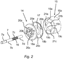
- This permanent magnet inner rotor is in Fig. 2 shown in an exploded representation closer.
- the motor shaft 7 has a front shaft end 7a to which the impeller 3 is to be fastened.
- the motor shaft 7 on its outer circumferential wall has a knurling 16, which is designed to fix the holder 14 in a rotationally fixed manner on the motor shaft 7.
- Bearing surface portions 7b, 7d form seats for the shaft bearings 11, 12 and a thrust bearing 27 which are adapted to rotatably support the motor shaft 7 in the motor housing 9.
- the permanent magnet ring 15 of the rotor 13 is in the wet space 22 in direct contact with the liquid ( Fig. 1 ).
- the rotor 13 has a one-piece permanent magnet ring 15 made of an anisotropic ferromagnetic material, which is magnetized multipolar.
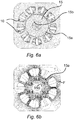
- the permanent magnet ring 15 is magnetized multipolar in such a way that each pair of poles 16.1 to 16.6, as in Fig. 6a and 6b shown schematically, in cross section of Permanent magnet ring 15 occupies a circular ring sector, so that the magnetic field lines F extending radially inwardly from an outer annular wall 15a of the permanent magnet ring 15, within the respective sector near an inner annular wall 15b of the permanent magnet ring 15 are arcuate and then in the direction of the outer annular wall 15a of the permanent magnet ring 15 again radially outwardly extend, as in particular in Fig. 6b is shown.
- the permanent magnet ring 15 is magnetized in the embodiment shown with six pole pairs 16.1 to 16.6, which are arranged distributed in equal sectors evenly over the circumference of the ring. However, the permanent magnet ring 15 can be designed, for example, with four or eight pole pairs.
- the holder 14 to form a drum-shaped receptacle for the permanent magnet ring 15 on a circular cylindrical sleeve portion 17 which is fixedly connected to the motor shaft 7.
- two circular discs 18a, 18b are arranged, each having a larger outer diameter than the sleeve portion 17, so that between the circular discs 18a, 18b of the permanent magnet ring 15 axially fixed by the circular discs 18a, 18b is held ,
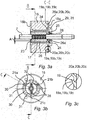
- the permanent magnet ring 15 has in the case of in the Fig. 3a to 3c illustrated embodiment, three anti-rotation 19 in the form of securing recesses 19a, 19b, 19c, which are adapted to engage in corresponding securing projections 20a, 20b, 20c, which are formed on at least one of the two circular discs 18a, 18b of the holder 14 to one another gripping position the permanent magnet ring 15 rotationally fixed to the holder 14 to fix.
- Each securing recess 19a, 19b, 19c is formed in the illustrated embodiment by a half-lens-shaped recess in an annular end wall in the permanent magnet ring 15.
- Each securing projection 20a, 20b, 20c is thereby formed by a corresponding half-lens-shaped projection on the holder 14, in particular on a circular disk wall facing the permanent magnet ring 15, of the at least one circular disk 18a, 18b.
- the permanent magnet ring 15 on three Positionierkerben 21 a, 21 b, 21 c which are adapted to keep the permanent magnet ring 15 during a Magnetisiervorgangs in a (not shown) magnetizing secured against rotation.
- the sleeve portion 17 has two flow channels 26.
- the two flow channels 26 are opposite, that is offset by 180 degrees to each other on a common circumference, as in particular in the Fig. 3b and Fig. 4 is shown.
- Each flow channel 26 is adapted to transport liquid located in the wet space 22 from a first end face 23 of the holder 14 to an axially opposite second face end 24 of the holder 14.
- Each flow channel 26 extends parallel to the axial length of the motor shaft 7.
- the sleeve portion 17 has an inner jacket wall 25, which completely engages the motor shaft 7 circumferentially on the motor shaft 7, as in particular in Fig. 4 you can see.
- Each flow channel 26 extends in a radial distance A to the motor shaft 7 completely in the interior of the sleeve portion 17.
- Each flow channel 26 in this case has a circumferentially closed-walled channel wall.
- the closed-walled channel wall is formed entirely of the material of the sleeve portion 17 of the holder 14.
- the wall thickness W is a sleeve inner wall 17a of the sleeve portion 17 located within the circumference of the at least one flow channel 26, as in FIG Fig. 4 shown, greater than the wall thickness V of a lying outside the circumference of the at least one flow channel 26 sleeve outer wall 17b of the sleeve portion 17th
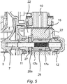
- the flow channels 26 open in particular on the outlet side (see arrows in FIG Fig. 5 ) on an end wall 28 of a holder 14 formed on the bearing seat 29, in which the thrust bearing 27 is held.
- the bearing seat 29 has several evenly over a Circumferentially distributed, to form flow openings 30 spaced from each other projections 31 which extend away from the end wall 28 of the holder 14 in the axial direction.
- the projections 31 have the thrust bearing 27 facing inner surfaces 32 which are formed flat to the line-contacting concerns on the thrust bearing 27.
- the sleeve portion 17 has a plurality of axially extending, evenly distributed over a circumference blind hole-like recesses 33.
- the recesses 33 have a circular ring segment-shaped contour in cross-section.
- Each flow channel 26 is formed by a respective recess 33, the blind hole-like recess 33 forming closed end wall 34 is formed open.
- the closed end wall 34 is replaced in this respect by the cross-sectional widening flow channel end portion 26a.
Landscapes
- Engineering & Computer Science (AREA)
- Power Engineering (AREA)
- Structures Of Non-Positive Displacement Pumps (AREA)
- Connection Of Motors, Electrical Generators, Mechanical Devices, And The Like (AREA)
- Motor Or Generator Frames (AREA)
Claims (12)
- Appareil ménager, notamment lave-vaisselle ou lave-linge, comprenant une pompe (1) qui présente un moteur d'entraînement (8) muni d'un enroulement de stator (10) commandable électriquement et d'un rotor (13) logé de manière à pouvoir être entraîné par rotation dans le champ de l'enroulement de stator (10) dans une chambre humide (22) du moteur d'entraînement (8), le rotor (13) présentant un arbre moteur (7), un aimant de rotor (15) réalisé comme anneau à aimant permanent et un support (14) qui est fixé sur l'arbre moteur (7) en tant que pièce en matière plastique moulée par injection et sur lequel est maintenu l'aimant de rotor (15), le support (14) comprenant une section de douille (17) s'étendant entre l'arbre moteur (7) et l'aimant de rotor (15), laquelle présente au moins un canal d'écoulement (26) qui est réalisé pour transporter le liquide présent dans la chambre humide (22) à travers le support (14), le support (14) reposant sur toute la circonférence de l'arbre moteur (7), l'au moins un canal d'écoulement (26) s'étendant complètement à l'intérieur de la section de douille (17) avec un écart radial (A) par rapport à l'arbre moteur (7), l'au moins un canal d'écoulement (26) présentant une paroi de canal à paroi fermée sur le pourtour, et la paroi de canal à paroi fermée étant entièrement formée à partir de la matière de la section de douille (17) du support (14) fabriqué selon le procédé de moulage par injection de matière plastique.
- Appareil ménager selon la revendication 1, caractérisé en ce que l'épaisseur de paroi (W) d'une paroi intérieure (17a) de douille, située à l'intérieur de la circonférence de l'au moins un canal d'écoulement (26), de la section de douille (17) est plus grande que l'épaisseur de paroi (V) d'une paroi extérieure (17b) de douille, située à l'extérieur de la circonférence de l'au moins un canal d'écoulement (26), de la section de douille (17).
- Appareil ménager selon l'une quelconque des revendications 1 ou 2, caractérisé en ce que l'au moins un canal d'écoulement (26) présente au moins côté sortie une section terminale (26a) de canal d'écoulement s'élargissant en section transversale.
- Appareil ménager selon l'une quelconque des revendications 1 à 3, caractérisé en ce que l'au moins un canal d'écoulement (26) aboutit, notamment côté sortie, sur une paroi frontale (28) d'un siège de palier (29) réalisé sur le support (14), dans lequel est maintenu un palier lisse ou un palier à roulement (11, 12), notamment un palier axial (27), lequel est réalisé pour loger le rotor (13) de manière rotative par rapport à l'enroulement de stator (10).
- Appareil ménager selon la revendication 4, caractérisé en ce que le siège de palier (29) présente plusieurs saillies (31) distancées les unes des autres, réparties régulièrement sur une circonférence pour la formation de passages d'écoulement (30), lesquelles s'étendent en direction axiale en s'éloignant de la paroi frontale (28) du support (14).
- Appareil ménager selon la revendication 5, caractérisé en ce que les saillies (31) présentent des surfaces intérieures (32) tournées vers le palier axial (27), lesquelles surfaces intérieures sont réalisées de manière plane pour l'application sur le palier axial (27) en touchant la ligne.
- Appareil ménager selon l'une quelconque des revendications 1 à 6, caractérisé en ce que la section de douille (17) présente plusieurs évidements (33) en forme de trou borgne s'étendant axialement en longueur, répartis de manière régulière sur une circonférence.
- Appareil ménager selon la revendication 7, caractérisé en ce que les évidements (33) présentent un contour en forme de segment d'anneau de cercle en section transversale.
- Appareil ménager selon la revendication 7 ou 8, caractérisé en ce que l'au moins un canal d'écoulement (26), notamment en ce que deux ou plusieurs canaux d'écoulement (26) sont respectivement formés par un évidement, dont la paroi frontale (34) fermée formant l'évidement (33) en forme de trou borgne est réalisée de manière ouverte.
- Appareil ménager selon l'une quelconque des revendications 1 à 9, caractérisé en ce que le rotor présente un anneau à aimant permanent (15) d'une seule pièce constitué d'une matière ferromagnétique anisotrope, lequel est magnétisé de manière pluripolaire, notamment avec quatre, six ou huit pôles.
- Appareil ménager selon l'une quelconque des revendications 1 à 10, caractérisé en ce qu'un dispositif anti-rotation est ménagé pour éviter une rotation de l'anneau à aimant permanent (15) autour de l'axe du rotor (13) sur le support (14), lequel dispositif anti-rotation est formé par au moins une saillie de sécurité sur l'anneau à aimant permanent (15), ayant prise par adhérence de forme dans respectivement au moins un retrait de sécurité sur le support (14), et/ou par au moins une saillie de sécurité (20a, 20b, 20c) sur le support (14), ayant prise par adhérence de forme dans respectivement au moins un retrait de sécurité (19a, 19b, 19c) sur l'anneau à aimant permanent (15).
- Appareil ménager selon la revendication 11, caractérisé en ce que le support (15) présente une section de douille (17) en forme de cylindre à anneau circulaire, qui est reliée de manière fixe à l'arbre moteur (7), et, sur des côtés frontaux axialement opposés de la section de douille en forme de cylindre à anneau circulaire, deux disques circulaire (18a, 18b) délimitant latéralement l'anneau à aimant permanent (15), dont au moins un disque circulaire présente une paroi de disque circulaire tournée vers l'anneau à aimant permanent (15), laquelle paroi présente l'au moins un retrait de sécurité et/ou l'au moins une saillie de sécurité.
Priority Applications (1)
| Application Number | Priority Date | Filing Date | Title |
|---|---|---|---|
| PL14730121T PL3011663T3 (pl) | 2013-06-19 | 2014-06-05 | Pompa z co najmniej jednym kanałem przepływowym i urządzenie gospodarstwa domowego z taką pompą |
Applications Claiming Priority (2)
| Application Number | Priority Date | Filing Date | Title |
|---|---|---|---|
| DE102013211574.1A DE102013211574A1 (de) | 2013-06-19 | 2013-06-19 | Pumpe mit wenigstens einem Strömungskanal und Haushaltsgerät mit einer solchen Pumpe |
| PCT/EP2014/061729 WO2014202397A2 (fr) | 2013-06-19 | 2014-06-05 | Pompe pourvue d'au moins un canal d'écoulement et appareil ménager comprenant une telle pompe |
Publications (2)
| Publication Number | Publication Date |
|---|---|
| EP3011663A2 EP3011663A2 (fr) | 2016-04-27 |
| EP3011663B1 true EP3011663B1 (fr) | 2017-08-09 |
Family
ID=50942673
Family Applications (1)
| Application Number | Title | Priority Date | Filing Date |
|---|---|---|---|
| EP14730121.2A Active EP3011663B1 (fr) | 2013-06-19 | 2014-06-05 | Pompe pourvue d'au moins un canal d'écoulement et appareil ménager comprenant une telle pompe |
Country Status (6)
| Country | Link |
|---|---|
| EP (1) | EP3011663B1 (fr) |
| CN (1) | CN205248951U (fr) |
| DE (1) | DE102013211574A1 (fr) |
| ES (1) | ES2639723T3 (fr) |
| PL (1) | PL3011663T3 (fr) |
| WO (1) | WO2014202397A2 (fr) |
Cited By (2)
| Publication number | Priority date | Publication date | Assignee | Title |
|---|---|---|---|---|
| DE102019207325A1 (de) * | 2019-05-20 | 2020-11-26 | Zf Friedrichshafen Ag | Kühlanordnung für eine elektrische Maschine und elektrische Maschine |
| DE102021205945A1 (de) | 2021-06-11 | 2022-12-15 | Bühler Motor GmbH | Verfahren zur Herstellung eines Rotors einer elektrischen Antriebseinheit |
Families Citing this family (5)
| Publication number | Priority date | Publication date | Assignee | Title |
|---|---|---|---|---|
| DE102016211251A1 (de) * | 2016-06-23 | 2017-12-28 | Robert Bosch Gmbh | Rotor für eine elektrische Maschine, elektrische Maschine mit dem Rotor und Herstellungsverfahren für den Rotor |
| DE102017203736A1 (de) * | 2017-03-07 | 2018-09-13 | Mahle International Gmbh | Elektromotor |
| DE102017206089B4 (de) * | 2017-04-10 | 2020-01-16 | BSH Hausgeräte GmbH | Nassläufer-Pumpe und Haushaltsgerät |
| JP6871289B2 (ja) * | 2019-03-04 | 2021-05-12 | 本田技研工業株式会社 | ロータ及び回転電機 |
| US12255508B2 (en) * | 2020-02-26 | 2025-03-18 | Amotech Co., Ltd. | Axial gap type motor and water pump using same |
Family Cites Families (7)
| Publication number | Priority date | Publication date | Assignee | Title |
|---|---|---|---|---|
| US4080112A (en) * | 1976-02-03 | 1978-03-21 | March Manufacturing Company | Magnetically-coupled pump |
| US4414523A (en) * | 1981-09-04 | 1983-11-08 | Micropump Corporation | Encapsulated magnet for magnetic drive |
| DE19545561A1 (de) * | 1995-12-07 | 1997-06-12 | Pierburg Ag | Pumpe-Motoreinheit |
| DE10051239A1 (de) * | 2000-10-17 | 2002-04-25 | Buhler Motor Gmbh | Nasslaufender Permanentmagnet-Rotor |
| EP1427087B1 (fr) | 2002-11-26 | 2006-01-11 | Grundfos a/s | Rotor pour un moteur submersible |
| ATE467938T1 (de) | 2005-11-18 | 2010-05-15 | Askoll Holding Srl | Verfahren zur herstellung eines permanentmagnetischen läufers für einen synchronmotor insbesondere für eine waschmaschinenpumpe für den hausgebrauch und industrielle anwendungen und ähnliches, und entsprechender läufer |
| DE102011079224B3 (de) * | 2011-07-15 | 2012-12-06 | Bühler Motor GmbH | Kreiselpumpenlaufrad einer durch einen elektronisch kommutierten Gleichstrommotor angetriebenen Kreiselpumpe |
-
2013
- 2013-06-19 DE DE102013211574.1A patent/DE102013211574A1/de not_active Withdrawn
-
2014
- 2014-06-05 ES ES14730121.2T patent/ES2639723T3/es active Active
- 2014-06-05 PL PL14730121T patent/PL3011663T3/pl unknown
- 2014-06-05 WO PCT/EP2014/061729 patent/WO2014202397A2/fr not_active Ceased
- 2014-06-05 CN CN201490000831.2U patent/CN205248951U/zh not_active Expired - Lifetime
- 2014-06-05 EP EP14730121.2A patent/EP3011663B1/fr active Active
Non-Patent Citations (1)
| Title |
|---|
| None * |
Cited By (3)
| Publication number | Priority date | Publication date | Assignee | Title |
|---|---|---|---|---|
| DE102019207325A1 (de) * | 2019-05-20 | 2020-11-26 | Zf Friedrichshafen Ag | Kühlanordnung für eine elektrische Maschine und elektrische Maschine |
| US11527939B2 (en) | 2019-05-20 | 2022-12-13 | Zf Friedrichshafen Ag | Cooling arrangement for an electric machine, and electric machine |
| DE102021205945A1 (de) | 2021-06-11 | 2022-12-15 | Bühler Motor GmbH | Verfahren zur Herstellung eines Rotors einer elektrischen Antriebseinheit |
Also Published As
| Publication number | Publication date |
|---|---|
| DE102013211574A1 (de) | 2014-12-24 |
| EP3011663A2 (fr) | 2016-04-27 |
| PL3011663T3 (pl) | 2018-01-31 |
| WO2014202397A3 (fr) | 2015-06-11 |
| WO2014202397A2 (fr) | 2014-12-24 |
| CN205248951U (zh) | 2016-05-18 |
| ES2639723T3 (es) | 2017-10-30 |
Similar Documents
| Publication | Publication Date | Title |
|---|---|---|
| EP3011661B1 (fr) | Pompe avec sécurité anti-torsion et appareil ménager équipé d'une telle pompe | |
| EP3011663B1 (fr) | Pompe pourvue d'au moins un canal d'écoulement et appareil ménager comprenant une telle pompe | |
| EP2908407B1 (fr) | Moteur d'entraînement électrique, pompe et appareil ménager doté d'une telle pompe | |
| EP3105838B1 (fr) | Moteur d'entraînement électrique, pompe et appareil ménager équipé d'une telle pompe | |
| DE102011079226B4 (de) | Flüssigkeitspumpe, insbesondere Wasserpumpe | |
| DE102017203736A1 (de) | Elektromotor | |
| AT510446A4 (de) | Elektrische maschine | |
| DE112016002202T5 (de) | Elektrische Rotationsmaschine | |
| EP3765712A1 (fr) | Système modulaire d'une structure de pompe axialement intégrée | |
| DE102013212616A1 (de) | Rotor für eine elektrische Maschine, wobei an dem Rotor über seinen Umfang mehrere Rotorpole angeordnet sind | |
| WO2018069104A1 (fr) | Moteur d'entraînement électrique | |
| DE202015101403U1 (de) | Maschine zum Wäschewaschen bzw. Wäschetrocknen | |
| WO2023061663A1 (fr) | Rotor et machine électrique à refroidissement de tête d'enroulement intégré, procédé de fabrication et véhicule automobile | |
| DE112016000819T5 (de) | Elektrische Rotationsmaschine, vorzugsweise für ein Hybridmotorfahrzeug | |
| DE102007049209B4 (de) | Gleichstrommotor | |
| DE10240800B4 (de) | Pumpe für chemisch aggressive Fördermedien | |
| EP3385961B1 (fr) | Aimant permanent monolithique | |
| DE10051239A1 (de) | Nasslaufender Permanentmagnet-Rotor | |
| EP3379085A1 (fr) | Rotor externe de pompe encapsulé et équilibré | |
| DE102019118646A1 (de) | Spritzgegossener Magnethalter für einen bürstenlosen Elektromotor | |
| EP1209799B1 (fr) | Rotor d'une machine électrique et son procédé de fabrication | |
| DE102011079225A1 (de) | Flüssigkeitspumpe, insbesondere Wasserpumpe | |
| DE19824135A1 (de) | Förderaggregat für Kraftstoff | |
| LU102802B1 (de) | Nassläuferpumpe | |
| DE102018116987A1 (de) | Rotoreinheit für einen bürstenlosen Elektromotor mit einstückigen Magnetflussleitern |
Legal Events
| Date | Code | Title | Description |
|---|---|---|---|
| PUAI | Public reference made under article 153(3) epc to a published international application that has entered the european phase |
Free format text: ORIGINAL CODE: 0009012 |
|
| 17P | Request for examination filed |
Effective date: 20160119 |
|
| AK | Designated contracting states |
Kind code of ref document: A2 Designated state(s): AL AT BE BG CH CY CZ DE DK EE ES FI FR GB GR HR HU IE IS IT LI LT LU LV MC MK MT NL NO PL PT RO RS SE SI SK SM TR |
|
| AX | Request for extension of the european patent |
Extension state: BA ME |
|
| DAX | Request for extension of the european patent (deleted) | ||
| REG | Reference to a national code |
Ref country code: DE Ref legal event code: R079 Ref document number: 502014004952 Country of ref document: DE Free format text: PREVIOUS MAIN CLASS: H02K0005128000 Ipc: H02K0001270000 |
|
| GRAP | Despatch of communication of intention to grant a patent |
Free format text: ORIGINAL CODE: EPIDOSNIGR1 |
|
| RIC1 | Information provided on ipc code assigned before grant |
Ipc: H02K 1/32 20060101ALI20170306BHEP Ipc: H02K 1/27 20060101AFI20170306BHEP Ipc: H02K 5/128 20060101ALI20170306BHEP Ipc: H02K 1/30 20060101ALI20170306BHEP |
|
| INTG | Intention to grant announced |
Effective date: 20170323 |
|
| GRAS | Grant fee paid |
Free format text: ORIGINAL CODE: EPIDOSNIGR3 |
|
| GRAA | (expected) grant |
Free format text: ORIGINAL CODE: 0009210 |
|
| AK | Designated contracting states |
Kind code of ref document: B1 Designated state(s): AL AT BE BG CH CY CZ DE DK EE ES FI FR GB GR HR HU IE IS IT LI LT LU LV MC MK MT NL NO PL PT RO RS SE SI SK SM TR |
|
| REG | Reference to a national code |
Ref country code: GB Ref legal event code: FG4D Free format text: NOT ENGLISH |
|
| REG | Reference to a national code |
Ref country code: CH Ref legal event code: EP Ref country code: AT Ref legal event code: REF Ref document number: 917816 Country of ref document: AT Kind code of ref document: T Effective date: 20170815 |
|
| REG | Reference to a national code |
Ref country code: IE Ref legal event code: FG4D Free format text: LANGUAGE OF EP DOCUMENT: GERMAN |
|
| REG | Reference to a national code |
Ref country code: DE Ref legal event code: R096 Ref document number: 502014004952 Country of ref document: DE |
|
| REG | Reference to a national code |
Ref country code: ES Ref legal event code: FG2A Ref document number: 2639723 Country of ref document: ES Kind code of ref document: T3 Effective date: 20171030 |
|
| REG | Reference to a national code |
Ref country code: NL Ref legal event code: MP Effective date: 20170809 |
|
| REG | Reference to a national code |
Ref country code: LT Ref legal event code: MG4D |
|
| PG25 | Lapsed in a contracting state [announced via postgrant information from national office to epo] |
Ref country code: HR Free format text: LAPSE BECAUSE OF FAILURE TO SUBMIT A TRANSLATION OF THE DESCRIPTION OR TO PAY THE FEE WITHIN THE PRESCRIBED TIME-LIMIT Effective date: 20170809 Ref country code: SE Free format text: LAPSE BECAUSE OF FAILURE TO SUBMIT A TRANSLATION OF THE DESCRIPTION OR TO PAY THE FEE WITHIN THE PRESCRIBED TIME-LIMIT Effective date: 20170809 Ref country code: NO Free format text: LAPSE BECAUSE OF FAILURE TO SUBMIT A TRANSLATION OF THE DESCRIPTION OR TO PAY THE FEE WITHIN THE PRESCRIBED TIME-LIMIT Effective date: 20171109 Ref country code: LT Free format text: LAPSE BECAUSE OF FAILURE TO SUBMIT A TRANSLATION OF THE DESCRIPTION OR TO PAY THE FEE WITHIN THE PRESCRIBED TIME-LIMIT Effective date: 20170809 Ref country code: NL Free format text: LAPSE BECAUSE OF FAILURE TO SUBMIT A TRANSLATION OF THE DESCRIPTION OR TO PAY THE FEE WITHIN THE PRESCRIBED TIME-LIMIT Effective date: 20170809 Ref country code: FI Free format text: LAPSE BECAUSE OF FAILURE TO SUBMIT A TRANSLATION OF THE DESCRIPTION OR TO PAY THE FEE WITHIN THE PRESCRIBED TIME-LIMIT Effective date: 20170809 |
|
| PG25 | Lapsed in a contracting state [announced via postgrant information from national office to epo] |
Ref country code: LV Free format text: LAPSE BECAUSE OF FAILURE TO SUBMIT A TRANSLATION OF THE DESCRIPTION OR TO PAY THE FEE WITHIN THE PRESCRIBED TIME-LIMIT Effective date: 20170809 Ref country code: RS Free format text: LAPSE BECAUSE OF FAILURE TO SUBMIT A TRANSLATION OF THE DESCRIPTION OR TO PAY THE FEE WITHIN THE PRESCRIBED TIME-LIMIT Effective date: 20170809 Ref country code: IS Free format text: LAPSE BECAUSE OF FAILURE TO SUBMIT A TRANSLATION OF THE DESCRIPTION OR TO PAY THE FEE WITHIN THE PRESCRIBED TIME-LIMIT Effective date: 20171209 Ref country code: BG Free format text: LAPSE BECAUSE OF FAILURE TO SUBMIT A TRANSLATION OF THE DESCRIPTION OR TO PAY THE FEE WITHIN THE PRESCRIBED TIME-LIMIT Effective date: 20171109 Ref country code: GR Free format text: LAPSE BECAUSE OF FAILURE TO SUBMIT A TRANSLATION OF THE DESCRIPTION OR TO PAY THE FEE WITHIN THE PRESCRIBED TIME-LIMIT Effective date: 20171110 |
|
| PG25 | Lapsed in a contracting state [announced via postgrant information from national office to epo] |
Ref country code: CZ Free format text: LAPSE BECAUSE OF FAILURE TO SUBMIT A TRANSLATION OF THE DESCRIPTION OR TO PAY THE FEE WITHIN THE PRESCRIBED TIME-LIMIT Effective date: 20170809 Ref country code: RO Free format text: LAPSE BECAUSE OF FAILURE TO SUBMIT A TRANSLATION OF THE DESCRIPTION OR TO PAY THE FEE WITHIN THE PRESCRIBED TIME-LIMIT Effective date: 20170809 Ref country code: DK Free format text: LAPSE BECAUSE OF FAILURE TO SUBMIT A TRANSLATION OF THE DESCRIPTION OR TO PAY THE FEE WITHIN THE PRESCRIBED TIME-LIMIT Effective date: 20170809 |
|
| REG | Reference to a national code |
Ref country code: DE Ref legal event code: R097 Ref document number: 502014004952 Country of ref document: DE |
|
| PG25 | Lapsed in a contracting state [announced via postgrant information from national office to epo] |
Ref country code: SM Free format text: LAPSE BECAUSE OF FAILURE TO SUBMIT A TRANSLATION OF THE DESCRIPTION OR TO PAY THE FEE WITHIN THE PRESCRIBED TIME-LIMIT Effective date: 20170809 Ref country code: SK Free format text: LAPSE BECAUSE OF FAILURE TO SUBMIT A TRANSLATION OF THE DESCRIPTION OR TO PAY THE FEE WITHIN THE PRESCRIBED TIME-LIMIT Effective date: 20170809 Ref country code: EE Free format text: LAPSE BECAUSE OF FAILURE TO SUBMIT A TRANSLATION OF THE DESCRIPTION OR TO PAY THE FEE WITHIN THE PRESCRIBED TIME-LIMIT Effective date: 20170809 |
|
| PLBE | No opposition filed within time limit |
Free format text: ORIGINAL CODE: 0009261 |
|
| STAA | Information on the status of an ep patent application or granted ep patent |
Free format text: STATUS: NO OPPOSITION FILED WITHIN TIME LIMIT |
|
| 26N | No opposition filed |
Effective date: 20180511 |
|
| PG25 | Lapsed in a contracting state [announced via postgrant information from national office to epo] |
Ref country code: SI Free format text: LAPSE BECAUSE OF FAILURE TO SUBMIT A TRANSLATION OF THE DESCRIPTION OR TO PAY THE FEE WITHIN THE PRESCRIBED TIME-LIMIT Effective date: 20170809 |
|
| PG25 | Lapsed in a contracting state [announced via postgrant information from national office to epo] |
Ref country code: MT Free format text: LAPSE BECAUSE OF FAILURE TO SUBMIT A TRANSLATION OF THE DESCRIPTION OR TO PAY THE FEE WITHIN THE PRESCRIBED TIME-LIMIT Effective date: 20170809 |
|
| REG | Reference to a national code |
Ref country code: CH Ref legal event code: PL |
|
| GBPC | Gb: european patent ceased through non-payment of renewal fee |
Effective date: 20180605 |
|
| REG | Reference to a national code |
Ref country code: BE Ref legal event code: MM Effective date: 20180630 |
|
| REG | Reference to a national code |
Ref country code: IE Ref legal event code: MM4A |
|
| PG25 | Lapsed in a contracting state [announced via postgrant information from national office to epo] |
Ref country code: MC Free format text: LAPSE BECAUSE OF FAILURE TO SUBMIT A TRANSLATION OF THE DESCRIPTION OR TO PAY THE FEE WITHIN THE PRESCRIBED TIME-LIMIT Effective date: 20170809 Ref country code: LU Free format text: LAPSE BECAUSE OF NON-PAYMENT OF DUE FEES Effective date: 20180605 |
|
| PG25 | Lapsed in a contracting state [announced via postgrant information from national office to epo] |
Ref country code: LI Free format text: LAPSE BECAUSE OF NON-PAYMENT OF DUE FEES Effective date: 20180630 Ref country code: FR Free format text: LAPSE BECAUSE OF NON-PAYMENT OF DUE FEES Effective date: 20180630 Ref country code: CH Free format text: LAPSE BECAUSE OF NON-PAYMENT OF DUE FEES Effective date: 20180630 Ref country code: IE Free format text: LAPSE BECAUSE OF NON-PAYMENT OF DUE FEES Effective date: 20180605 Ref country code: GB Free format text: LAPSE BECAUSE OF NON-PAYMENT OF DUE FEES Effective date: 20180605 |
|
| PG25 | Lapsed in a contracting state [announced via postgrant information from national office to epo] |
Ref country code: BE Free format text: LAPSE BECAUSE OF NON-PAYMENT OF DUE FEES Effective date: 20180630 |
|
| PG25 | Lapsed in a contracting state [announced via postgrant information from national office to epo] |
Ref country code: PT Free format text: LAPSE BECAUSE OF FAILURE TO SUBMIT A TRANSLATION OF THE DESCRIPTION OR TO PAY THE FEE WITHIN THE PRESCRIBED TIME-LIMIT Effective date: 20170809 |
|
| PG25 | Lapsed in a contracting state [announced via postgrant information from national office to epo] |
Ref country code: CY Free format text: LAPSE BECAUSE OF FAILURE TO SUBMIT A TRANSLATION OF THE DESCRIPTION OR TO PAY THE FEE WITHIN THE PRESCRIBED TIME-LIMIT Effective date: 20170809 Ref country code: MK Free format text: LAPSE BECAUSE OF NON-PAYMENT OF DUE FEES Effective date: 20170809 Ref country code: HU Free format text: LAPSE BECAUSE OF FAILURE TO SUBMIT A TRANSLATION OF THE DESCRIPTION OR TO PAY THE FEE WITHIN THE PRESCRIBED TIME-LIMIT; INVALID AB INITIO Effective date: 20140605 |
|
| PG25 | Lapsed in a contracting state [announced via postgrant information from national office to epo] |
Ref country code: AL Free format text: LAPSE BECAUSE OF FAILURE TO SUBMIT A TRANSLATION OF THE DESCRIPTION OR TO PAY THE FEE WITHIN THE PRESCRIBED TIME-LIMIT Effective date: 20170809 |
|
| REG | Reference to a national code |
Ref country code: AT Ref legal event code: MM01 Ref document number: 917816 Country of ref document: AT Kind code of ref document: T Effective date: 20190605 |
|
| PG25 | Lapsed in a contracting state [announced via postgrant information from national office to epo] |
Ref country code: AT Free format text: LAPSE BECAUSE OF NON-PAYMENT OF DUE FEES Effective date: 20190605 |
|
| P01 | Opt-out of the competence of the unified patent court (upc) registered |
Effective date: 20230504 |
|
| PGFP | Annual fee paid to national office [announced via postgrant information from national office to epo] |
Ref country code: DE Payment date: 20250630 Year of fee payment: 12 Ref country code: PL Payment date: 20250529 Year of fee payment: 12 |
|
| PGFP | Annual fee paid to national office [announced via postgrant information from national office to epo] |
Ref country code: TR Payment date: 20250529 Year of fee payment: 12 |
|
| PGFP | Annual fee paid to national office [announced via postgrant information from national office to epo] |
Ref country code: ES Payment date: 20250718 Year of fee payment: 12 |
|
| PGFP | Annual fee paid to national office [announced via postgrant information from national office to epo] |
Ref country code: IT Payment date: 20250630 Year of fee payment: 12 |