EP3011663B1 - Pump having at least one flow channel and household appliance having such a pump - Google Patents
Pump having at least one flow channel and household appliance having such a pump Download PDFInfo
- Publication number
- EP3011663B1 EP3011663B1 EP14730121.2A EP14730121A EP3011663B1 EP 3011663 B1 EP3011663 B1 EP 3011663B1 EP 14730121 A EP14730121 A EP 14730121A EP 3011663 B1 EP3011663 B1 EP 3011663B1
- Authority
- EP
- European Patent Office
- Prior art keywords
- holder
- permanent magnet
- wall
- rotor
- flow channel
- Prior art date
- Legal status (The legal status is an assumption and is not a legal conclusion. Google has not performed a legal analysis and makes no representation as to the accuracy of the status listed.)
- Active
Links
Images


Classifications
-
- H—ELECTRICITY
- H02—GENERATION; CONVERSION OR DISTRIBUTION OF ELECTRIC POWER
- H02K—DYNAMO-ELECTRIC MACHINES
- H02K1/00—Details of the magnetic circuit
- H02K1/06—Details of the magnetic circuit characterised by the shape, form or construction
- H02K1/22—Rotating parts of the magnetic circuit
- H02K1/27—Rotor cores with permanent magnets
- H02K1/2706—Inner rotors
- H02K1/272—Inner rotors the magnetisation axis of the magnets being perpendicular to the rotor axis
- H02K1/2726—Inner rotors the magnetisation axis of the magnets being perpendicular to the rotor axis the rotor consisting of a single magnet or two or more axially juxtaposed single magnets
- H02K1/2733—Annular magnets
-
- H—ELECTRICITY
- H02—GENERATION; CONVERSION OR DISTRIBUTION OF ELECTRIC POWER
- H02K—DYNAMO-ELECTRIC MACHINES
- H02K1/00—Details of the magnetic circuit
- H02K1/06—Details of the magnetic circuit characterised by the shape, form or construction
- H02K1/22—Rotating parts of the magnetic circuit
- H02K1/28—Means for mounting or fastening rotating magnetic parts on to, or to, the rotor structures
- H02K1/30—Means for mounting or fastening rotating magnetic parts on to, or to, the rotor structures using intermediate parts, e.g. spiders
-
- H—ELECTRICITY
- H02—GENERATION; CONVERSION OR DISTRIBUTION OF ELECTRIC POWER
- H02K—DYNAMO-ELECTRIC MACHINES
- H02K1/00—Details of the magnetic circuit
- H02K1/06—Details of the magnetic circuit characterised by the shape, form or construction
- H02K1/22—Rotating parts of the magnetic circuit
- H02K1/32—Rotating parts of the magnetic circuit with channels or ducts for flow of cooling medium
-
- H—ELECTRICITY
- H02—GENERATION; CONVERSION OR DISTRIBUTION OF ELECTRIC POWER
- H02K—DYNAMO-ELECTRIC MACHINES
- H02K5/00—Casings; Enclosures; Supports
- H02K5/04—Casings or enclosures characterised by the shape, form or construction thereof
- H02K5/12—Casings or enclosures characterised by the shape, form or construction thereof specially adapted for operating in liquid or gas
- H02K5/128—Casings or enclosures characterised by the shape, form or construction thereof specially adapted for operating in liquid or gas using air-gap sleeves or air-gap discs
Definitions
- the invention relates to a household appliance, in particular dishwasher or washing machine, with a pump.
- the EP 1 788 690 A1 describes a method for manufacturing a permanent magnet rotor for a synchronous motor, in particular for a pump of a washing machine for industrial and domestic use and the like, with an external stator comprising a cylindrical central core with an axis and an axial passage surrounded by a plurality of permanent magnets which has an outer arc surface and an inner arc surface and side edges, comprising the steps of disposing a cup-shaped body of a plastic material comprising a base end, an open end, a sidewall, and a plurality of longitudinally extending recesses formed in the sidewall are and define placement recordings for a placement of the magnets; Inserting the central core into the cup-like body and arranging the magnets in accordance with the placement receptacles; Injecting a plastic material into and around the cup-like body in correspondence with the recesses, thereby obtaining a cage-like structure having opposed bottoms and struts extending between the opposed bottoms, the opposing bottoms being adjacent the ends
- the EP 1 427 087 A1 describes a rotor for an electric motor, at its two axial ends in each case a cover plate is arranged, being integrally formed on a cover with this a system for a thrust bearing and formed on the other cover an axially outwardly directed stop ring integral with the cover is.
- a sleeve surrounding the rotor shaft and connecting the cover plates is provided inside the rotor.
- Inner lateral surface of the sleeve is provided to the outer shell surface of the rotor shaft open toward venting channel in the form of a longitudinal groove or longitudinal groove which extends in the axial direction through the rotor and is open to the outer sides of the cover.
- venting channel can serve in wet-running electric motors to achieve a venting example of the impeller facing away from the motor housing.
- the wet-running permanent magnet rotor of the electric motor of the centrifugal pump of DE 100 51 239 A1 has a first hub part with an outer boundary surface surrounded by a hollow second hub part with an inner boundary surface.
- the outer boundary surface of the first hub part has open mold grooves on the inner boundary surface of the second hub part arranged on the outside.
- the mutually facing boundary surfaces of both hub parts may have mutually associated, open flow channel contours, which together form at least one continuous flow channel remaining between the two hub parts.
- the first hub part consists of a magnetically conductive material, the second hub part of permanent magnet material. Outside on the second hub part, a ring magnet can be attached.
- the object of the invention is to provide a household appliance with a pump that is inexpensive and in particular has an improved service life and / or improved efficiency.
- the object of the invention is achieved by a domestic appliance, in particular dishwasher or washing machine, with a pump according to claim 1.
- This pump according to the invention has a drive motor with an electrically controllable stator winding and a rotatably mounted in the field of the stator winding in a wet space of the drive motor rotor.
- the rotor has a motor shaft, a rotor magnet formed as a permanent magnet ring and a holder which is fixed as a one-piece plastic injection molded part on the motor shaft. On the holder of the rotor magnet is held.
- the retainer includes a sleeve portion extending between the motor shaft and the rotor magnet and having at least one flow passage configured to convey liquid in the wet space through the retainer.
- the holder sits fully on The motor shaft on The at least one flow channel extends in a radial distance to the motor shaft completely in the interior of the sleeve portion.
- the at least one flow channel has a peripherally closed-walled channel wall.
- the closed-walled channel wall is formed entirely from the material of the sleeve section of the holder produced using the plastic injection molding process.
- the liquid in the wet space serves to cool and / or lubricate the rotor or the bearings of the rotor.
- the outer jacket wall of the rotor i. the rotor magnet constructively brought as close to the stator winding. This has the consequence that only a very small gap is present between the rotor or rotor magnet and the inner wall of the wet space, which can be traversed only very poorly by the liquid during a rotation of the rotor.
- a remote from a liquid inlet wet space area is very difficult to be flushed through this gap alone.
- a rear i.
- the wet room area facing away from the impeller undesirably accumulate air and / or vapor bubbles. Due to the rotation of the rotor, air bubbles and / or vapor bubbles tend to collect in the near-axis center of the wet space near the motor shaft and not in an outer circumference near the gap.
- the liquid can circulate through the holder and in particular air and / or vapor bubbles can be led out, so that there is no risk that the bearings of the rotor run dry, which reduce the life of the pump and the efficiency of the pump would.
- the at least one flow channel extends completely in the interior of the sleeve section at a radial distance from the motor shaft, no liquid can wet the motor shaft in the region in which the holder is seated on the motor shaft. As a result, for example, corrosion in this area can be prevented or at least reduced. Prevention of corrosion is particularly important in the area in which the holder is seated on the motor shaft, if there for better fixation of the holder on the motor shaft, the motor shaft on its surface has a knurl, which weakens the motor shaft anyway and prone to corrosion power. This is especially important if the liquid is, for example, a chemically active rinsing liquor of a dishwasher.
- the holder may rest fully on the motor shaft, ie, the holder has the largest possible contact area with the motor shaft peripheral wall, thereby rendering the holder particularly strong and reliable can be set on the motor shaft and so far prevents unwanted loosening of the holder of the motor shaft or the risk is at least significantly reduced.
- a single flow channel in particular two or more flow channels may be formed in the holder.
- the drive motor may be a brushless DC wet-running pump drive motor.
- the rotor magnet may generally be a permanent magnet ring attached to the holder.
- the at least one flow channel may be configured to transport liquid in the wet space from a first end of the holder to an axially opposite second end of the holder.
- the sleeve section may in particular have an inner jacket wall which completely surrounds the motor shaft over its circumference. In that regard, the sleeve portion may rest fully on the motor shaft.
- the at least one flow channel has according to the invention a circumferentially closed-walled channel wall.
- the closed-walled channel wall is formed completely from the material of the sleeve section of the holder produced by the plastic injection method. This ensures that liquid can be transported through the flow channel leak-free. In that regard, there is no need to seal any gaps. There is thus no danger that fluid can escape from the flow channel in an undesirable manner, which could wet the motor shaft in the region in which the holder is seated on the motor shaft.
- the wall thickness of a sleeve inside wall of the sleeve section which is located within the circumference of the at least one flow channel may, in a specific embodiment of the invention, be greater than the wall thickness of a sleeve outer wall of the sleeve section lying outside the circumference of the at least one flow channel.
- the circumference, on which the at least one flow channel is located divides the sleeve section into a sleeve-shaped outer wall section and also a sleeve-shaped inner wall section.
- the inner wall section has a greater wall thickness than the outer wall section.
- the wall thickness of the sleeve inner wall is greater than the wall thickness of the sleeve outer wall, a stable seat of the holder can be ensured on the motor shaft.
- the wall thickness of the sleeve outer wall is smaller than the wall thickness of the sleeve inner wall of the at least one flow channel is closer to the rotor magnet, which may be a permanent magnet ring generally, so that cooling of the rotor magnet or of the permanent magnet ring by through the liquid flowing at least one flow channel can be improved.
- the at least one flow channel can have, at least on the outlet side, a flow channel end section which widens in cross-section.
- a flow channel which is circular in cross-section in the region of the flow channel end section can transition into an, for example, more oval and / or arcuate flow channel.
- the exiting liquid can be better removed and, if appropriate, also better distributed on the axial bearing.
- the liquid can pass through at least predominantly or even completely through a central opening, in particular an annular gap, between the thrust bearing and the motor shaft and can be returned to the impeller via one of the further bearings of the motor shaft.
- the at least one flow channel in particular on the outlet side, open on an end wall of a bearing seat formed on the holder, in which a sliding or rolling bearing, in particular a thrust bearing, is held, which is designed to rotatably support the rotor with respect to the stator winding.
- the bearing seat may also have a plurality of uniformly distributed over a circumference, to form flow openings spaced apart projections which extend away from the end wall of the holder in the axial direction.
- the bearing seat can be designed in the manner of a crown-shaped holder.
- the projections may be formed in sections, forming the flow breakthroughs from a circumferential annular wall of the holder.
- the holder can generally be made as a particular one-piece plastic injection molded part.
- the projections may have the bearing, in particular thrust bearing facing inner surfaces which are designed to be linear contact with the bearing, in particular thrust bearing flat.
- the inner surfaces of the projections may form a polygonal pull as a seat so that an annular bearing is in line contact with this polygonal pull, i. abuts the inner surfaces of the projections.
- the sleeve portion may have a plurality of axially extending, evenly distributed over a circumference blind hole-like recesses. These recesses may have a circular ring segment-shaped contour in cross section.
- the blind hole-like recesses can reduce the amount of material and consequently the weight of the holder.
- the blind-hole-like recesses may in a specific embodiment form or at least co-form the flow channels according to the invention.
- the at least one flow channel in particular two or more flow channels can be formed by a respective recess, the blind hole-like recess forming closed end wall is formed opened.
- the closed end wall is replaced insofar by the flow channel end section widening in cross section.
- the pump may include a DC pump drive motor having an electrically controllable stator winding and a rotor rotatably mounted in the field of the stator winding, having a motor shaft, a permanent magnet ring and a holder mounted on the motor shaft and to which the permanent magnet Ring is held, wherein the pump has an anti-rotation, which is designed to secure the permanent magnet ring against rotation about the axis of the rotor on the holder.
- a low-cost pump can be provided in that the rotor is formed essentially only of the components of the motor shaft, the holder and the permanent magnet ring.
- the holder essentially serves to fasten the permanent magnet ring to the motor shaft. Since the permanent magnet ring has an annular basic shape and the permanent magnet ring coaxial with the motor shaft aligned fixed to the holder, there is quite a risk that due to the rotation of the driven during operation of the pump rotor, the permanent magnet ring in the rotational direction of the Can solve the holder and can go crazy so far.
- the pump having an anti-rotation device which is designed to secure the permanent magnet ring against rotation about the axis of the rotor on the holder, an undesired release of the permanent magnet ring from the holder can be prevented.
- the anti-rotation device can be formed by at least one securing projection which engages in a form-fitting manner in at least one securing recess.
- the at least one securing recess can be arranged on the holder and the respectively at least one associated securing projection on the permanent magnet ring, in particular be formed.
- the at least one securing recess on the permanent magnet ring and the respectively at least one associated securing projection on the holder can be arranged, in particular formed. This allows the holder and the permanent magnet ring positively engage with each other.
- two, in particular three or more pairs of securing recesses and securing projections can be formed on the rotor distributed over a circumference at regular intervals.
- the permanent magnet ring can be fixed in a plurality of different angular positions on the holder.
- two, in particular three or more pairs of securing recesses and securing projections can ensure better positive fixing than just a single pair of securing recess and securing projection.
- the holder may have a circular cylindrical sleeve portion to form a drum-shaped receptacle for the permanent magnet ring, which is fixedly connected to the motor shaft and on axially opposite end faces of the sleeve portion may be arranged laterally limiting the permanent magnet ring circular discs, of which at least one circular disc having the permanent magnet ring facing circular disk wall, which has the at least one securing recess and / or the at least one securing projection.
- the permanent magnet ring in contrast, can have the at least one corresponding securing recess and / or the at least one corresponding securing projection on at least one annular end wall which faces one of the circular disks of the holder.
- the circular discs of the holder limit the permanent magnet ring of two axial End faces and set as far as the permanent magnet ring initially only in the axial direction. Without an anti-rotation of the permanent magnet ring is fixed only non-positively or cohesively on the holder against rotation.
- at least one circular disc has a circular disk wall facing the permanent magnet ring, which has the at least one securing recess and / or the at least one securing projection, an additional positive locking attachment is provided, which in particular prevents the rotation of the permanent magnet ring on the drum-shaped receptacle.
- the securing recess can be formed by a half-lenticular recess in the permanent magnet ring, in particular in an annular end wall of the permanent magnet ring and the securing projection can be formed by a corresponding half lenticular projection on the holder, in particular on a circular disk wall facing the permanent magnet ring of the at least one circular disk become.
- the permanent magnet ring with such half-lens-shaped recesses and / or half-lens-shaped projections, sharp edges and / or corners in the surface of the permanent magnet ring can be avoided.
- the rotor may be formed as a permanent magnet inner rotor and be formed by a one-piece ring of an anisotropic ferromagnetic material which is magnetized multipolar.
- the permanent magnet ring can be magnetized in such a way multipolar, that each pair of poles in the cross section of the permanent magnet ring occupies a circular ring sector, such that the magnetic field lines of the outer shell wall of the permanent magnet ring starting radially extending inwardly, extend arcuately within the respective sector near the inner jacket wall of the permanent magnet ring and then extend radially outward in the direction of the outer jacket wall of the permanent magnet ring again.
- the permanent magnet ring can be magnetized, for example, with four or six pole pairs, which are arranged uniformly distributed in equal sectors over the circumference of the ring.
- the holder may have a circular-cylindrical sleeve portion to form a drum-shaped receptacle for the permanent magnet ring, which is fixedly connected to the motor shaft and arranged on axially opposite end faces of the sleeve portion two circular disks, each having a larger outer diameter than the sleeve portion and between them the permanent magnet ring is attached.
- At least one of the circular disks can have a bearing seat in which a sliding or roller bearing, in particular a thrust bearing, which is designed to rotatably support the permanent magnet inner rotor with respect to the stator winding.
- the bearing seat may have a bottom surface whose surface facing the bearing is spherical, in particular concave-spherical.
- a spherical bottom surface of the bearing seat may have a plurality of evenly distributed over the circumference of an outer ring of the bearing, spaced-apart projections extending away from an outer wall of at least one of the circular discs in the axial direction and their bearing facing inner surfaces for line-contacting concern the outer ring of the bearing are flat.
- the permanent magnet ring may comprise at least one, in particular three or more latching means, which are designed to engage in corresponding counter-latching means which on at least one of the two circular disks of Halters are formed to fix the permanent magnet ring in a locked position on the holder rotatably.
- the permanent magnet ring may have at least one, in particular three or more positioning notches, which are designed to keep the permanent magnet ring secured against rotation during a magnetizing operation in a magnetizing device.
- the DC pump drive motor can generally be designed as a liquid-flow wet-running motor and the permanent-magnet ring of the permanent-magnet inner rotor is in direct contact with the liquid.
- the invention also relates to a domestic appliance, in particular a dishwasher or a washing machine, which has a pump according to the invention as described.
- An in Fig. 1 exemplified pump 1 of a household appliance has a pump housing 2, in which a pump impeller 3 is rotatably arranged.
- the impeller 3 has a plurality of blades 4, which are formed and arranged to suck liquid via an inlet opening 5 axially and eject via an outlet opening 6 radially.
- the pump 1 thus forms a centrifugal pump in the design of a radial pump.
- the impeller 3 is non-rotatably mounted on a motor shaft 7 of a brushless DC wet-running pump drive motor 8.
- the DC wet rotor pump drive motor 8 is disposed in a motor housing 9.
- the motor housing 9 is connected directly to the pump housing 2 in the case of the present embodiment. If necessary, that can Motor housing 9 together with the pump housing 2 form a structural unit, or even be formed in one piece.
- the DC wet-rotor pump drive motor 8 has an electrically controllable stator winding 10 and a rotor 13 drivable in the field of the stator winding 10 and rotatably mounted by means of the motor shaft 7 in the field between two opposing bearings 11, 12.
- the DC wet-rotor pump drive motor 8 of the illustrated embodiment is designed as a liquid-flowed wet-rotor motor, in which the rotor 13 is mounted within a motor housing 9 in a wet space 22, which is flooded with liquid from the pump housing 2.
- the stator winding 10 is arranged in a dry environment outside of the motor housing 9.
- the rotor 13 substantially the motor shaft 7, a rotatably mounted on the motor shaft 7 holder 14 and a rotatably fixed to the holder 14 and axially fixed permanent magnet ring 15.
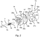
- This permanent magnet inner rotor is in Fig. 2 shown in an exploded representation closer.
- the motor shaft 7 has a front shaft end 7a to which the impeller 3 is to be fastened.
- the motor shaft 7 on its outer circumferential wall has a knurling 16, which is designed to fix the holder 14 in a rotationally fixed manner on the motor shaft 7.
- Bearing surface portions 7b, 7d form seats for the shaft bearings 11, 12 and a thrust bearing 27 which are adapted to rotatably support the motor shaft 7 in the motor housing 9.
- the permanent magnet ring 15 of the rotor 13 is in the wet space 22 in direct contact with the liquid ( Fig. 1 ).
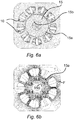
- the rotor 13 has a one-piece permanent magnet ring 15 made of an anisotropic ferromagnetic material, which is magnetized multipolar.
- the permanent magnet ring 15 is magnetized multipolar in such a way that each pair of poles 16.1 to 16.6, as in Fig. 6a and 6b shown schematically, in cross section of Permanent magnet ring 15 occupies a circular ring sector, so that the magnetic field lines F extending radially inwardly from an outer annular wall 15a of the permanent magnet ring 15, within the respective sector near an inner annular wall 15b of the permanent magnet ring 15 are arcuate and then in the direction of the outer annular wall 15a of the permanent magnet ring 15 again radially outwardly extend, as in particular in Fig. 6b is shown.
- the permanent magnet ring 15 is magnetized in the embodiment shown with six pole pairs 16.1 to 16.6, which are arranged distributed in equal sectors evenly over the circumference of the ring. However, the permanent magnet ring 15 can be designed, for example, with four or eight pole pairs.
- the holder 14 to form a drum-shaped receptacle for the permanent magnet ring 15 on a circular cylindrical sleeve portion 17 which is fixedly connected to the motor shaft 7.
- two circular discs 18a, 18b are arranged, each having a larger outer diameter than the sleeve portion 17, so that between the circular discs 18a, 18b of the permanent magnet ring 15 axially fixed by the circular discs 18a, 18b is held ,
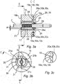
- the permanent magnet ring 15 has in the case of in the Fig. 3a to 3c illustrated embodiment, three anti-rotation 19 in the form of securing recesses 19a, 19b, 19c, which are adapted to engage in corresponding securing projections 20a, 20b, 20c, which are formed on at least one of the two circular discs 18a, 18b of the holder 14 to one another gripping position the permanent magnet ring 15 rotationally fixed to the holder 14 to fix.
- Each securing recess 19a, 19b, 19c is formed in the illustrated embodiment by a half-lens-shaped recess in an annular end wall in the permanent magnet ring 15.
- Each securing projection 20a, 20b, 20c is thereby formed by a corresponding half-lens-shaped projection on the holder 14, in particular on a circular disk wall facing the permanent magnet ring 15, of the at least one circular disk 18a, 18b.
- the permanent magnet ring 15 on three Positionierkerben 21 a, 21 b, 21 c which are adapted to keep the permanent magnet ring 15 during a Magnetisiervorgangs in a (not shown) magnetizing secured against rotation.
- the sleeve portion 17 has two flow channels 26.
- the two flow channels 26 are opposite, that is offset by 180 degrees to each other on a common circumference, as in particular in the Fig. 3b and Fig. 4 is shown.
- Each flow channel 26 is adapted to transport liquid located in the wet space 22 from a first end face 23 of the holder 14 to an axially opposite second face end 24 of the holder 14.
- Each flow channel 26 extends parallel to the axial length of the motor shaft 7.
- the sleeve portion 17 has an inner jacket wall 25, which completely engages the motor shaft 7 circumferentially on the motor shaft 7, as in particular in Fig. 4 you can see.
- Each flow channel 26 extends in a radial distance A to the motor shaft 7 completely in the interior of the sleeve portion 17.
- Each flow channel 26 in this case has a circumferentially closed-walled channel wall.
- the closed-walled channel wall is formed entirely of the material of the sleeve portion 17 of the holder 14.
- the wall thickness W is a sleeve inner wall 17a of the sleeve portion 17 located within the circumference of the at least one flow channel 26, as in FIG Fig. 4 shown, greater than the wall thickness V of a lying outside the circumference of the at least one flow channel 26 sleeve outer wall 17b of the sleeve portion 17th
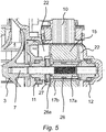
- the flow channels 26 open in particular on the outlet side (see arrows in FIG Fig. 5 ) on an end wall 28 of a holder 14 formed on the bearing seat 29, in which the thrust bearing 27 is held.
- the bearing seat 29 has several evenly over a Circumferentially distributed, to form flow openings 30 spaced from each other projections 31 which extend away from the end wall 28 of the holder 14 in the axial direction.
- the projections 31 have the thrust bearing 27 facing inner surfaces 32 which are formed flat to the line-contacting concerns on the thrust bearing 27.
- the sleeve portion 17 has a plurality of axially extending, evenly distributed over a circumference blind hole-like recesses 33.
- the recesses 33 have a circular ring segment-shaped contour in cross-section.
- Each flow channel 26 is formed by a respective recess 33, the blind hole-like recess 33 forming closed end wall 34 is formed open.
- the closed end wall 34 is replaced in this respect by the cross-sectional widening flow channel end portion 26a.
Landscapes
- Engineering & Computer Science (AREA)
- Power Engineering (AREA)
- Structures Of Non-Positive Displacement Pumps (AREA)
- Connection Of Motors, Electrical Generators, Mechanical Devices, And The Like (AREA)
- Motor Or Generator Frames (AREA)
Description
Die Erfindung betrifft ein Haushaltsgerät, insbesondere Geschirrspülmaschine oder Waschmaschine, mit einer Pumpe.The invention relates to a household appliance, in particular dishwasher or washing machine, with a pump.
Die
Die
Der nasslaufende Permanentmagnet- Rotor des Elektromotors der Kreiselpumpe der
Die Aufgabe der Erfindung ist es, ein Haushaltsgerät mit einer Pumpe zu schaffen, die kostengünstig ist und insbesondere eine verbesserte Lebensdauer und/oder einen verbesserten Wirkungsgrad aufweist.The object of the invention is to provide a household appliance with a pump that is inexpensive and in particular has an improved service life and / or improved efficiency.
Die Aufgabe der Erfindung wird gelöst durch ein Haushaltsgerät, insbesondere Geschirrspülmaschine oder Waschmaschine, mit einer Pumpe gemäß dem Anspruch 1. Diese erfindungsgemäße Pumpe weist einen Antriebsmotor mit einer elektrisch ansteuerbaren Statorwicklung und einem im Feld der Statorwicklung in einem Nassraum des Antriebsmotors drehantreibbar gelagerten Rotor auf. Der Rotor weist eine Motorwelle, einen als Permanentmagnet-Ring ausgebildeten Rotormagneten und einen Halter auf, der als einstückiges Kunststoffspritzgussteil auf der Motorwelle befestigt ist. An dem Halter ist der Rotormagnet gehalten. Der Halter umfasst einen sich zwischen der Motorwelle und dem Rotormagneten erstreckenden Hülsenabschnitt, der wenigstens einen Strömungskanal aufweist, der ausgebildet ist, in dem Nassraum befindliche Flüssigkeit durch den Halter zu transportieren. Erfindungsgemäß sitzt der Halter vollumfänglich auf der Motorwelle auf Der wenigstens eine Strömungskanal erstreckt sich in einem radialen Abstand zur Motorwelle vollständig im Inneren des Hülsenabschnitts. Dabei weist der wenigstens eine Strömungskanal eine umfänglich geschlossenwandige Kanalwand auf. Die geschlossenwandige Kanalwand wird vollständig aus dem Material des Hülsenabschnitts des im Kunststoffspritzgussverfahren gefertigten Halters gebildet.The object of the invention is achieved by a domestic appliance, in particular dishwasher or washing machine, with a pump according to
Die im Nassraum befindliche Flüssigkeit dient unter anderem der Kühlung und/oder Schmierung des Rotors bzw. der Lager des Rotors. Um einen hohen elektromagnetischen Wirkungsgrad zu erreichen, wird die äußere Mantelwand des Rotors, d.h. des Rotormagneten konstruktiv möglichst nahe an die Statorwicklung herangeführt. Dies hat zur Folge, dass zwischen Rotor bzw. Rotormagnet und der Innenwand des Nassraums nur ein sehr geringer Spalt vorhanden ist, der insbesondere während einer Rotation des Rotors nur sehr schlecht von der Flüssigkeit durchströmt werden kann. Insoweit kann ein von einem Flüssigkeitszulauf abgewandter Nassraumbereich nur sehr schwer allein über diesen Spalt durchspült werden. Insbesondere kann in einem solchen hinteren, d.h. dem Pumpenrad abgewandten Nassraumbereich sich in unerwünschter Weise Luft- und/oder Dampfblasen ansammeln. Aufgrund der Rotation des Rotors sammeln sich tendenziell Luft- und/oder Dampfblasen im achsnahen Zentrum des Nassraumes nahe der Motorwelle und nicht in einem äußeren Umfang nahe des Spaltes. Mittels des wenigstens einen erfindungsgemäßen Strömungskanals kann die Flüssigkeit durch den Halter hindurch zirkulieren und insbesondere können Luft- und/oder Dampfblasen herausgeführt werden, so dass keine Gefahr besteht, dass die Lager des Rotors trockenlaufen, was die Lebensdauer der Pumpe und den Wirkungsgrad der Pumpe reduzieren würde. Durch ein Abführen von Luft- und/oder Dampfblasen läuft der Antriebsmotor und damit auch die Pumpe außerdem leiser.Among other things, the liquid in the wet space serves to cool and / or lubricate the rotor or the bearings of the rotor. In order to achieve high electromagnetic efficiency, the outer jacket wall of the rotor, i. the rotor magnet constructively brought as close to the stator winding. This has the consequence that only a very small gap is present between the rotor or rotor magnet and the inner wall of the wet space, which can be traversed only very poorly by the liquid during a rotation of the rotor. In that regard, a remote from a liquid inlet wet space area is very difficult to be flushed through this gap alone. In particular, in such a rear, i. The wet room area facing away from the impeller undesirably accumulate air and / or vapor bubbles. Due to the rotation of the rotor, air bubbles and / or vapor bubbles tend to collect in the near-axis center of the wet space near the motor shaft and not in an outer circumference near the gap. By means of the at least one flow channel according to the invention, the liquid can circulate through the holder and in particular air and / or vapor bubbles can be led out, so that there is no risk that the bearings of the rotor run dry, which reduce the life of the pump and the efficiency of the pump would. By discharging air and / or vapor bubbles of the drive motor and thus also the pump runs quieter.
Indem der wenigstens eine Strömungskanal sich in einem radialen Abstand zur Motorwelle vollständig im Inneren des Hülsenabschnitts erstreckt, kann keine Flüssigkeit die Motorwelle in dem Bereich benetzen, in dem der Halter auf der Motorwelle aufsitzt. Dadurch kann beispielsweise Korrosion in diesem Bereich verhindert oder zumindest reduziert werden. Eine Vermeidung von Korrosion ist ganz besonders in dem Bereich, in dem der Halter auf der Motorwelle aufsitzt wichtig, wenn dort zur besseren Fixierung des Halters auf der Motorwelle, die Motorwelle an ihrer Oberfläche eine Rändelung aufweist, welche die Motorwelle sowieso schwächt und anfällig für Korrosion macht. Dies ist besonders dann von Bedeutung, wenn es sich bei der Flüssigkeit beispielsweise um eine chemisch aktive Spülflotte einer Geschirrspülmaschine handelt. Wenn der wenigstens eine Strömungskanal sich in einem radialen Abstand zur Motorwelle vollständig im Inneren des Hülsenabschnitts erstreckt, kann außerdem der Halter vollumfänglich auf der Motorwelle aufsitzen, d.h. der Halter hat mit einer größtmöglichen Fläche Kontakt zur Mantelwand der Motorwelle, wodurch der Halter besonders fest und zuverlässig auf der Motorwelle festgelegt sein kann und insoweit ein unerwünschtes Lösen des Halters von der Motorwelle verhindert oder die Gefahr dazu zumindest deutlich verringert ist. Statt eines einzigen Strömungskanals können insbesondere zwei oder auch mehrere Strömungskanäle in dem Halter ausgebildet sein.Since the at least one flow channel extends completely in the interior of the sleeve section at a radial distance from the motor shaft, no liquid can wet the motor shaft in the region in which the holder is seated on the motor shaft. As a result, for example, corrosion in this area can be prevented or at least reduced. Prevention of corrosion is particularly important in the area in which the holder is seated on the motor shaft, if there for better fixation of the holder on the motor shaft, the motor shaft on its surface has a knurl, which weakens the motor shaft anyway and prone to corrosion power. This is especially important if the liquid is, for example, a chemically active rinsing liquor of a dishwasher. In addition, if the at least one flow channel extends completely within the sleeve portion at a radial distance from the motor shaft, the holder may rest fully on the motor shaft, ie, the holder has the largest possible contact area with the motor shaft peripheral wall, thereby rendering the holder particularly strong and reliable can be set on the motor shaft and so far prevents unwanted loosening of the holder of the motor shaft or the risk is at least significantly reduced. Instead of a single flow channel, in particular two or more flow channels may be formed in the holder.
Die folgenden Merkmale können einzeln oder in Kombination zueinander in unterschiedlichen Ausführungsformen Anwendung finden: Generell kann es sich bei dem Antriebsmotor um einen bürstenlosen Gleichstrom-Nassläufer-Pumpenantriebsmotor handeln. Bei dem Rotormagneten kann es sich generell um einen Permanentmagnet-Ring handeln, der an dem Halter befestigt ist. Der wenigstens einen Strömungskanal kann ausgebildet sein, in dem Nassraum befindliche Flüssigkeit von einem ersten Stirnende des Halters zu einem axial gegenüberliegenden zweiten Stirnende des Halters zu transportieren. Der Hülsenabschnitt kann insbesondere eine innere Mantelwand aufweisen, welche die Motorwelle über ihren Umfang hinweg vollständig umschließt. Insoweit kann der Hülsenabschnitt an der Motorwelle vollumfänglich anliegen.The following features may be used individually or in combination in different embodiments: Generally, the drive motor may be a brushless DC wet-running pump drive motor. The rotor magnet may generally be a permanent magnet ring attached to the holder. The at least one flow channel may be configured to transport liquid in the wet space from a first end of the holder to an axially opposite second end of the holder. The sleeve section may in particular have an inner jacket wall which completely surrounds the motor shaft over its circumference. In that regard, the sleeve portion may rest fully on the motor shaft.
Der wenigstens eine Strömungskanal weist erfindungsgemäß eine umfänglich geschlossenwandige Kanalwand auf. Dabei wird die geschlossenwandige Kanalwand erfindungsgemäß vollständig aus dem Material des Hülsenabschnitts des im Kunststoffspritzverfahrens gefertigten Halters gebildet. Dadurch ist sichergestellt, dass Flüssigkeit durch den Strömungskanal leckagefrei transportiert werden kann. Insoweit besteht keine Notwendigkeit, eventuelle Spalte abzudichten. Es besteht damit auch keine Gefahr, dass aus dem Strömungskanal in unerwünschter Weise Flüssigkeit austreten kann, welche die Motorwelle in dem Bereich benetzen könnte, in dem der Halter auf der Motorwelle aufsitzt.The at least one flow channel has according to the invention a circumferentially closed-walled channel wall. According to the invention, the closed-walled channel wall is formed completely from the material of the sleeve section of the holder produced by the plastic injection method. This ensures that liquid can be transported through the flow channel leak-free. In that regard, there is no need to seal any gaps. There is thus no danger that fluid can escape from the flow channel in an undesirable manner, which could wet the motor shaft in the region in which the holder is seated on the motor shaft.
Die Wandstärke einer innerhalb des Umfangs des wenigstens einen Strömungskanals liegenden Hülsen-Innenwand des Hülsenabschnitts kann in einer speziellen Ausführungsform der Erfindung größer sein, als die Wandstärke einer außerhalb des Umfangs des wenigstens einen Strömungskanals liegenden Hülsen-Außenwand des Hülsenabschnitts. Mit anderen Worten teilt der Umfang, auf dem der wenigstens eine Strömungskanal liegt den Hülsenabschnitt in einen hülsenförmigen Außenwandabschnitt und einen ebenfalls hülsenförmigen Innenwandabschnitt. Der Innenwandabschnitt weist dabei eine größere Wandstärke auf, als der Außenwandabschnitt. Indem die Wandstärke der Hülsen-Innenwand größer ist als die Wandstärke der Hülsen-Außenwand, kann ein stabiler Sitz des Halters auf der Motorwelle gewährleistet sein. Indem die Wandstärke der Hülsen-Außenwand kleiner ist als die Wandstärke der Hülsen-Innenwand liegt der wenigstens eine Strömungskanal näher an dem Rotormagneten, der generell ein Permanentmagnet-Ring sein kann, so dass eine Kühlung des Rotormagneten bzw. des Permanentmagnet-Rings durch die durch den wenigstens einen Strömungskanal fließende Flüssigkeit verbessert sein kann.The wall thickness of a sleeve inside wall of the sleeve section which is located within the circumference of the at least one flow channel may, in a specific embodiment of the invention, be greater than the wall thickness of a sleeve outer wall of the sleeve section lying outside the circumference of the at least one flow channel. In other words, the circumference, on which the at least one flow channel is located, divides the sleeve section into a sleeve-shaped outer wall section and also a sleeve-shaped inner wall section. The inner wall section has a greater wall thickness than the outer wall section. By the wall thickness of the sleeve inner wall is greater than the wall thickness of the sleeve outer wall, a stable seat of the holder can be ensured on the motor shaft. By the wall thickness of the sleeve outer wall is smaller than the wall thickness of the sleeve inner wall of the at least one flow channel is closer to the rotor magnet, which may be a permanent magnet ring generally, so that cooling of the rotor magnet or of the permanent magnet ring by through the liquid flowing at least one flow channel can be improved.
In allen Ausführungen kann der wenigstens eine Strömungskanal zumindest austrittsseitig einen sich im Querschnitt erweiternden Strömungskanal-Endabschnitt aufweisen. Dabei kann beispielsweise ein im Querschnitt kreisförmiger Strömungskanal im Bereich des Strömungskanal-Endabschnitts in einen beispielsweise eher ovalen und/oder bogenförmigen Strömungskanal übergehen. Indem der wenigstens eine Strömungskanal zumindest austrittsseitig einen sich im Querschnitt erweiternden Strömungskanal-Endabschnitt aufweist, kann die austretende Flüssigkeit besser abgeführt werden und sich gegebenenfalls auch besser an dem Axiallager verteilen. Die Flüssigkeit kann zumindest überwiegend oder sogar vollständig durch eine zentrale Öffnung, insbesondere einen Ringspalt zwischen dem Axiallager und der Motorwelle hindurchtreten und über eines der weiteren Lager der Motorwelle zu dem Pumpenrad zurückgeführt werden.In all embodiments, the at least one flow channel can have, at least on the outlet side, a flow channel end section which widens in cross-section. there For example, a flow channel which is circular in cross-section in the region of the flow channel end section can transition into an, for example, more oval and / or arcuate flow channel. By virtue of the fact that the at least one flow channel, at least on the outlet side, has a flow channel end section which widens in cross-section, the exiting liquid can be better removed and, if appropriate, also better distributed on the axial bearing. The liquid can pass through at least predominantly or even completely through a central opening, in particular an annular gap, between the thrust bearing and the motor shaft and can be returned to the impeller via one of the further bearings of the motor shaft.
Insoweit kann in allen Ausführungen der wenigstens eine Strömungskanal insbesondere austrittsseitig an einer Stirnwand eines am Halter ausgebildeten Lagersitzes münden, in dem ein Gleit- oder Wälzlager, insbesondere ein Axiallager gehalten ist, welches ausgebildet ist, den Rotor bezüglich der Statorwicklung drehbar zu lagern.In that regard, in all embodiments, the at least one flow channel, in particular on the outlet side, open on an end wall of a bearing seat formed on the holder, in which a sliding or rolling bearing, in particular a thrust bearing, is held, which is designed to rotatably support the rotor with respect to the stator winding.
Der Lagersitz kann außerdem mehrere gleichmäßig über einen Umfang verteilte, zur Bildung von Strömungsdurchbrüchen voneinander beabstandete Vorsprünge aufweisen, die sich von der Stirnwand des Halters in axialer Richtung weg erstrecken. Der Lagersitz kann dabei in Art eines kronenförmigen Halters ausgeführt sein. Die Vorsprünge können abschnittsweise unter Bildung der Strömungsdurchbrüche aus einer umlaufenden kreisringförmigen Wand des Halters gebildet werden. Der Halter kann generell als ein insbesondere einstückiges Kunststoffspritzgussteil gefertigt sein.The bearing seat may also have a plurality of uniformly distributed over a circumference, to form flow openings spaced apart projections which extend away from the end wall of the holder in the axial direction. The bearing seat can be designed in the manner of a crown-shaped holder. The projections may be formed in sections, forming the flow breakthroughs from a circumferential annular wall of the holder. The holder can generally be made as a particular one-piece plastic injection molded part.
Die Vorsprünge können dem Lager, insbesondere Axiallager zugewandte Innenflächen aufweisen, die zum linienberührenden Anliegen an dem Lager, insbesondere Axiallager eben ausgebildet sind. Insoweit können die Innenflächen der Vorsprünge einen polygonen Zug als Sitzfläche bilden, so dass ein kreisringförmiges Lager linienberührend an diesem polygonen Zug d.h. an den Innenflächen der Vorsprünge anliegt.The projections may have the bearing, in particular thrust bearing facing inner surfaces which are designed to be linear contact with the bearing, in particular thrust bearing flat. In that regard, the inner surfaces of the projections may form a polygonal pull as a seat so that an annular bearing is in line contact with this polygonal pull, i. abuts the inner surfaces of the projections.
Generell kann der Hülsenabschnitt mehrere, sich axial längserstreckende, gleichmäßig über einen Umfang verteilte sacklochartige Ausnehmungen aufweisen. Diese Ausnehmungen können im Querschnitt eine kreisringsegmentförmige Kontur aufweisen. Die sacklochartigen Ausnehmungen können die Materialmenge und folglich das Gewicht des Halters reduzieren. Außerdem können im Fall eines im Kunststoffspritzgussverfahren gefertigten Halters Lunker und Einfallstellen verhindert oder zumindest vermieden werden, die sich beim Abkühlen und Schrumpfen des Kunststoffmaterials des Halters ergeben könnten. Darüber hinaus können die sacklochartigen Ausnehmungen in einer speziellen Ausführungsform die erfindungsgemäßen Strömungskanäle bilden oder zumindest mitbilden. Insoweit kann beispielsweise der wenigstens eine Strömungskanal, insbesondere können zwei oder mehrere Strömungskanäle durch jeweils eine Ausnehmung gebildet werden, deren die sacklochartige Ausnehmung bildende geschlossen Stirnwand eröffnet ausgebildet ist. Die geschlossen Stirnwand ist insoweit durch den sich im Querschnitt erweiternden Strömungskanal-Endabschnitt ersetzt.In general, the sleeve portion may have a plurality of axially extending, evenly distributed over a circumference blind hole-like recesses. These recesses may have a circular ring segment-shaped contour in cross section. The blind hole-like recesses can reduce the amount of material and consequently the weight of the holder. In addition, in the case of a plastic injection molding process manufactured holders cavities and sinkholes prevented or at least avoided, which could arise during cooling and shrinking of the plastic material of the holder. In addition, the blind-hole-like recesses may in a specific embodiment form or at least co-form the flow channels according to the invention. In that regard, for example, the at least one flow channel, in particular two or more flow channels can be formed by a respective recess, the blind hole-like recess forming closed end wall is formed opened. The closed end wall is replaced insofar by the flow channel end section widening in cross section.
In ergänzenden Ausführungsformen kann die Pumpe einen Gleichstrom-Pumpenantriebsmotor mit einer elektrisch ansteuerbaren Statorwicklung und einem im Feld der Statorwicklung drehantreibbar gelagerten Rotor aufweisen, der eine Motorwelle, einen Permanentmagnet-Ring und einen Halter aufweist, der auf der Motorwelle befestigt ist und an dem der Permanentmagnet-Ring gehalten ist, wobei die Pumpe eine Verdrehsicherung aufweist, die ausgebildet ist, den Permanentmagnet-Ring gegen ein Verdrehen um die Achse des Rotors auf dem Halter zu sichern.In supplemental embodiments, the pump may include a DC pump drive motor having an electrically controllable stator winding and a rotor rotatably mounted in the field of the stator winding, having a motor shaft, a permanent magnet ring and a holder mounted on the motor shaft and to which the permanent magnet Ring is held, wherein the pump has an anti-rotation, which is designed to secure the permanent magnet ring against rotation about the axis of the rotor on the holder.
Eine kostengünstige Pumpe kann dadurch geschaffen werden, dass der Rotor im Wesentlichen lediglich aus den Bauteilen der Motorwelle, des Halters und des Permanentmagnet-Rings gebildet wird. Der Halter dient im Wesentlichen dazu, den Permanentmagnet-Ring an der Motorwelle zu befestigen. Da der Permanentmagnet-Ring eine ringförmige Grundgestalt aufweist und der Permanentmagnet-Ring koaxial zur Motorwelle ausgerichtet an dem Halter festgelegt ist, besteht ganz allgemein die Gefahr, dass sich aufgrund der Drehung des im Betrieb der Pumpe angetriebenen Rotors der Permanentmagnet-Ring in Rotationsrichtung von dem Halter lösen kann und insoweit durchdrehen kann. Indem die Pumpe eine Verdrehsicherung aufweist, die ausgebildet ist, den Permanentmagnet-Ring gegen ein Verdrehen um die Achse des Rotors auf dem Halter zu sichern, kann ein unerwünschtes Lösen des Permanentmagnet-Rings von dem Halter verhindert werden.A low-cost pump can be provided in that the rotor is formed essentially only of the components of the motor shaft, the holder and the permanent magnet ring. The holder essentially serves to fasten the permanent magnet ring to the motor shaft. Since the permanent magnet ring has an annular basic shape and the permanent magnet ring coaxial with the motor shaft aligned fixed to the holder, there is quite a risk that due to the rotation of the driven during operation of the pump rotor, the permanent magnet ring in the rotational direction of the Can solve the holder and can go crazy so far. By the pump having an anti-rotation device, which is designed to secure the permanent magnet ring against rotation about the axis of the rotor on the holder, an undesired release of the permanent magnet ring from the holder can be prevented.
Die Verdrehsicherung kann von wenigstens einem formschlüssig in jeweils wenigstens einen Sicherungsrücksprung eingreifenden Sicherungsvorsprung gebildet werden. Durch eine solche Paarung von Sicherungsrücksprung und Sicherungsvorsprung wird eine zusätzliche formschlüssige Verbindung von Permanentmagnet-Ring und Halter geschaffen, die insbesondere eine Verdrehen des Permanentmagnet-Rings auf dem Halter zuverlässig verhindern kann.The anti-rotation device can be formed by at least one securing projection which engages in a form-fitting manner in at least one securing recess. By such a pairing of securing return and securing projection becomes a created additional positive connection of permanent magnet ring and holder, which can reliably prevent in particular a rotation of the permanent magnet ring on the holder.
Der wenigstens eine Sicherungsrücksprung kann an dem Halter und der jeweils wenigstens eine zugeordnete Sicherungsvorsprung an dem Permanentmagnet-Ring angeordnet, insbesondere ausgebildet sein. Alternativ oder ergänzend kann der wenigstens eine Sicherungsrücksprung an dem Permanentmagnet-Ring und der jeweils wenigstens eine zugeordnete Sicherungsvorsprung an dem Halter angeordnet, insbesondere ausgebildet sein. Dadurch können der Halter und der Permanentmagnet-Ring formschlüssig ineinander greifen.The at least one securing recess can be arranged on the holder and the respectively at least one associated securing projection on the permanent magnet ring, in particular be formed. Alternatively or additionally, the at least one securing recess on the permanent magnet ring and the respectively at least one associated securing projection on the holder can be arranged, in particular formed. This allows the holder and the permanent magnet ring positively engage with each other.
In allen Ausführungsformen können über einen Umfang in gleichmäßigen Abständen verteilt zwei, insbesondere drei oder mehrere Paare von Sicherungsrücksprüngen und Sicherungsvorsprüngen am Rotor ausgebildet sein. Indem über einen Umfang in gleichmäßigen Abständen verteilt zwei, insbesondere drei oder mehrere Paare von Sicherungsrücksprüngen und Sicherungsvorsprüngen am Rotor vorgesehen werden, kann der Permanentmagnet-Ring in mehreren verschiedenen Winkelstellungen auf dem Halter fixiert werden. Daneben können zwei, insbesondere drei oder mehrere Paare von Sicherungsrücksprüngen und Sicherungsvorsprüngen eine bessere formschlüssige Fixierung sicherstellen, als nur ein einziges Paar von Sicherungsrücksprung und Sicherungsvorsprung.In all embodiments, two, in particular three or more pairs of securing recesses and securing projections can be formed on the rotor distributed over a circumference at regular intervals. By two, in particular three or more pairs of securing recesses and securing projections are provided on the rotor distributed over a circumference at regular intervals, the permanent magnet ring can be fixed in a plurality of different angular positions on the holder. In addition, two, in particular three or more pairs of securing recesses and securing projections can ensure better positive fixing than just a single pair of securing recess and securing projection.
Der Halter kann zur Bildung einer trommelförmigen Aufnahme für den Permanentmagnet-Ring einen kreisringzylindrischen Hülsenabschnitt aufweisen, der fest mit der Motorwelle verbunden ist und an axial gegenüberliegenden Stirnseiten des Hülsenabschnitts können zwei den Permanentmagnet-Ring seitlich begrenzende Kreisscheiben angeordnet sein, von denen wenigstens eine Kreisscheibe eine dem Permanentmagnet-Ring zugewandte Kreisscheibenwand aufweist, welche den wenigstens einen Sicherungsrücksprung und/oder den wenigstens einen Sicherungsvorsprung aufweist. Der Permanentmagnet-Ring hingegen kann an wenigstens einer Ringstirnwand, die einer der Kreisscheiben des Halters zugewandt ist, den wenigstens einen korrespondierenden Sicherungsrücksprung und/oder den wenigstens einen korrespondierenden Sicherungsvorsprung aufweisen. Die Kreisscheiben des Halters begrenzen den Permanentmagnet-Ring von zwei axialen Stirnseiten und legen insoweit den Permanentmagnet-Ring zunächst nur in axialer Richtung fest. Ohne eine Verdrehsicherung ist der Permanentmagnet-Ring lediglich kraftschlüssig oder stoffschlüssig auf dem Halter gegen Verdrehen fixiert. Indem wenigstens eine Kreisscheibe eine dem Permanentmagnet-Ring zugewandte Kreisscheibenwand aufweist, welche den wenigstens einen Sicherungsrücksprung und/oder den wenigstens einen Sicherungsvorsprung aufweist, wird eine zusätzliche formschlüssig wirkende Befestigung geschaffen, welche insbesondere das Verdrehen des Permanentmagnet-Rings auf der trommelförmigen Aufnahme verhindert.The holder may have a circular cylindrical sleeve portion to form a drum-shaped receptacle for the permanent magnet ring, which is fixedly connected to the motor shaft and on axially opposite end faces of the sleeve portion may be arranged laterally limiting the permanent magnet ring circular discs, of which at least one circular disc having the permanent magnet ring facing circular disk wall, which has the at least one securing recess and / or the at least one securing projection. The permanent magnet ring, in contrast, can have the at least one corresponding securing recess and / or the at least one corresponding securing projection on at least one annular end wall which faces one of the circular disks of the holder. The circular discs of the holder limit the permanent magnet ring of two axial End faces and set as far as the permanent magnet ring initially only in the axial direction. Without an anti-rotation of the permanent magnet ring is fixed only non-positively or cohesively on the holder against rotation. By at least one circular disc has a circular disk wall facing the permanent magnet ring, which has the at least one securing recess and / or the at least one securing projection, an additional positive locking attachment is provided, which in particular prevents the rotation of the permanent magnet ring on the drum-shaped receptacle.
Der Sicherungsrücksprung kann von einer halblinsenförmigen Vertiefung in dem Permanentmagnet-Ring, insbesondere in einer Ringstirnwand des Permanentmagnet-Rings gebildet werden und der Sicherungsvorsprung kann von einem korrespondierenden halblinsenförmigen Vorsprung an dem Halter, insbesondere an einer dem Permanentmagnet-Ring zugewandten Kreisscheibenwand der wenigstens einen Kreisscheibe gebildet werden. Indem insbesondere der Permanentmagnet-Ring mit derartigen halblinsenförmigen Vertiefungen und/oder halblinsenförmigen Vorsprüngen versehen wird, können scharfe Kanten und/oder Ecken in der Oberfläche des Permanentmagnet-Rings vermieden werden. Da scharfe Kanten und/oder Ecken in der Oberfläche des Permanentmagnet-Rings Spannungsrisse verursachen oder zumindest begünstigen können, ist es besonders bei den im Allgemeinen eher spröden Werkstoffen, die für den Permanentmagnet-Ring verwendet werden können, sinnvoll Kanten und/oder Ecken zu vermeiden, um Spannungsrisse verhindern oder deren Auftreten vermeiden oder deren Verbreitung verzögern zu können. Dadurch lässt sich trotz Ausbildung von Vertiefungen und/oder Vorsprüngen an dem Permanentmagnet-Ring Ausschuss in der Herstellung verhindern bzw. reduzieren und die Lebensdauer des Permanentmagnet-Rings im Betrieb und folglich der gesamten Pumpe verlängern.The securing recess can be formed by a half-lenticular recess in the permanent magnet ring, in particular in an annular end wall of the permanent magnet ring and the securing projection can be formed by a corresponding half lenticular projection on the holder, in particular on a circular disk wall facing the permanent magnet ring of the at least one circular disk become. In particular, by providing the permanent magnet ring with such half-lens-shaped recesses and / or half-lens-shaped projections, sharp edges and / or corners in the surface of the permanent magnet ring can be avoided. Since sharp edges and / or corners in the surface of the permanent magnet ring can cause or at least promote stress cracks, it is sensible to avoid edges and / or corners, especially in the generally rather brittle materials that can be used for the permanent magnet ring in order to prevent stress cracks or prevent their occurrence or to delay their spread. As a result, despite the formation of depressions and / or projections on the permanent magnet ring, rejects in the production can be prevented or reduced and the service life of the permanent magnet ring during operation and consequently of the entire pump can be extended.
Der Rotor kann als ein Permanentmagnet-Innenrotor ausgebildet sein und von einem einteiligen Ring aus einem anisotropen ferromagnetischen Material gebildet werden, der mehrpolig magnetisiert ist.The rotor may be formed as a permanent magnet inner rotor and be formed by a one-piece ring of an anisotropic ferromagnetic material which is magnetized multipolar.
Der Permanentmagnet-Ring kann derart mehrpolig magnetisiert sein, dass jedes Polpaar im Querschnitt des Permanentmagnet-Rings einen Kreisringsektor einnimmt, derart dass die magnetischen Feldlinien von der äußeren Mantelwand des Permanentmagnet-Ringes ausgehend sich radial nach innen erstrecken, innerhalb des jeweiligen Sektors nahe der inneren Mantelwand des Permanentmagnet-Ringes bogenförmig verlaufen und sich dann in Richtung der äußeren Mantelwand des Permanentmagnet-Ringes wieder radial nach außen erstrecken.The permanent magnet ring can be magnetized in such a way multipolar, that each pair of poles in the cross section of the permanent magnet ring occupies a circular ring sector, such that the magnetic field lines of the outer shell wall of the permanent magnet ring starting radially extending inwardly, extend arcuately within the respective sector near the inner jacket wall of the permanent magnet ring and then extend radially outward in the direction of the outer jacket wall of the permanent magnet ring again.
Der Permanentmagnet-Ring kann beispielsweise mit vier oder sechs Polpaaren magnetisiert sein, die in gleichgroßen Sektoren gleichmäßig über den Umfang des Ringes verteilt angeordnet sind.The permanent magnet ring can be magnetized, for example, with four or six pole pairs, which are arranged uniformly distributed in equal sectors over the circumference of the ring.
Der Halter kann zur Bildung einer trommelförmigen Aufnahme für den Permanentmagnet-Ring einen kreisringzylindrischen Hülsenabschnitt aufweisen, der fest mit der Motorwelle verbunden ist und an axial gegenüberliegenden Stirnseiten des Hülsenabschnitts zwei Kreisscheiben angeordnet sind, die jeweils einen größeren Außendurchmesser aufweisen, als der Hülsenabschnitt und zwischen denen der Permanentmagnet-Ring befestigt ist.The holder may have a circular-cylindrical sleeve portion to form a drum-shaped receptacle for the permanent magnet ring, which is fixedly connected to the motor shaft and arranged on axially opposite end faces of the sleeve portion two circular disks, each having a larger outer diameter than the sleeve portion and between them the permanent magnet ring is attached.
In den Ausführungen, in denen der Halter Kreisscheiben aufweist kann wenigstens einer der Kreisscheiben einen Lagersitz aufweisen, in dem ein Gleit- oder Wälzlager, insbesondere Axiallager gehalten ist, welches ausgebildet ist, den Permanentmagnet-Innenrotor bezüglich der Statorwicklung drehbar zu lagern.In the embodiments in which the holder has circular disks, at least one of the circular disks can have a bearing seat in which a sliding or roller bearing, in particular a thrust bearing, which is designed to rotatably support the permanent magnet inner rotor with respect to the stator winding.
Der Lagersitz kann eine Bodenfläche aufweisen, deren dem Lager zugewandte Oberfläche sphärisch, insbesondere konkav-sphärisch ausgebildet ist.The bearing seat may have a bottom surface whose surface facing the bearing is spherical, in particular concave-spherical.
Alternativ oder ergänzend zu einer sphärischen Bodenfläche kann der Lagersitz mehrere gleichmäßig über den Umfang eines Außenringes des Lagers verteilte, voneinander beabstandete Vorsprünge aufweisen, die sich von einer Außenwand wenigstens eines der Kreisscheiben in axialer Richtung weg erstrecken und deren dem Lager zugewandte Innenflächen zum linienberührenden Anliegen an dem Außenring des Lagers eben ausgebildet sind.Alternatively or in addition to a spherical bottom surface of the bearing seat may have a plurality of evenly distributed over the circumference of an outer ring of the bearing, spaced-apart projections extending away from an outer wall of at least one of the circular discs in the axial direction and their bearing facing inner surfaces for line-contacting concern the outer ring of the bearing are flat.
In allen Ausführungen kann der Permanentmagnet-Ring wenigstens ein, insbesondere drei oder mehrere Rastmittel aufweisen, die ausgebildet sind, in korrespondierende Gegenrastmittel einzugreifen, die an wenigstens einem der beiden Kreisscheiben des Halters ausgebildet sind, um in einer verrasteten Position den Permanentmagnet-Ring drehfest an dem Halter zu fixieren.In all embodiments, the permanent magnet ring may comprise at least one, in particular three or more latching means, which are designed to engage in corresponding counter-latching means which on at least one of the two circular disks of Halters are formed to fix the permanent magnet ring in a locked position on the holder rotatably.
In allen Ausführungen kann der Permanentmagnet-Ring wenigstens eine, insbesondere drei oder mehrere Positionierkerben aufweisen, die ausgebildet sind, den Permanentmagnet-Ring während eines Magnetisiervorgangs in einer Magnetisiervorrichtung gegen Verdrehen gesichert zu halten.In all embodiments, the permanent magnet ring may have at least one, in particular three or more positioning notches, which are designed to keep the permanent magnet ring secured against rotation during a magnetizing operation in a magnetizing device.
Ganz allgemein kann der Gleichstrom-Pumpenantriebsmotor generell als ein von Flüssigkeit durchströmter Nassläufermotor ausgebildet sein und der Permanentmagnet-Ring des Permanentmagnet-Innenrotors dabei in unmittelbarem Kontakt zur Flüssigkeit stehen.In general, the DC pump drive motor can generally be designed as a liquid-flow wet-running motor and the permanent-magnet ring of the permanent-magnet inner rotor is in direct contact with the liquid.
Die Erfindung betrifft außerdem ein Haushaltsgerät, insbesondere eine Geschirrspülmaschine oder eine Waschmaschine, die eine erfindungsgemäße Pumpe, wie beschrieben, aufweist.The invention also relates to a domestic appliance, in particular a dishwasher or a washing machine, which has a pump according to the invention as described.
Ein Ausführungsbeispiel der Erfindung ist exemplarisch in den beigefügten schematischen Zeichnungen dargestellt.An embodiment of the invention is illustrated by way of example in the accompanying schematic drawings.
Es zeigen:
- Fig. 1
- eine Querschnittsansicht einer beispielhaften Pumpe eines Haushaltsgeräts mit einem erfindungsgemäßen Gleichstrom-Nassläufer-Pumpenantriebsmotor,
- Fig. 2
- eine perspektivische Explosionsdarstellung eines erfindungsgemäßen Permanentmagnet-Innenrotors des Gleichstrom-Nassläufer-Pumpenantriebsmotors gemäß
Fig. 1 ; - Fig. 3a
- einen Längsschnitt entlang der Schnittlinie C-C gemäß
Fig. 3b durch den Permanentmagnet-Innenrotor gemäßFig. 2 in einem montierten Zustand; - Fig. 3b
- eine Draufsicht in axialer Richtung auf den Permanentmagnet-Innenrotor gemäß
Fig. 3a ; - Fig. 3c
- einen vergrößerten Ausschnitt aus der
Fig. 3a im Bereich einer Verdrehsicherung; - Fig. 4
- eine Querschnittsansicht durch den Permanentmagnet-Innenrotor entlang der Schnittlinie B-B gemäß
Fig. 3a ; - Fig. 5
- eine vergrößerte Teilquerschnittsansicht der beispielhaften Pumpe im Bereich eines erfindungsgemäßen Halters des Permanentmagnet-Innenrotors gemäß
Fig. 3a mit einer Darstellung von erfindungsgemäßen Strömungskanälen; - Fig. 6a
- eine Querschnittsansicht durch den Gleichstrom-Nassläufer-Pumpenantriebsmotor mit dem im Feld der Statorwicklung drehbar gelagerten Permanentmagnet-Innenrotor; und
- Fig. 6b
- eine schematische Darstellung der magnetischen Feldlinien im Querschnitt durch den Gleichstrom-Nassläufer-Pumpenantriebsmotor mit dem im Feld der Statorwicklung drehbar gelagerten Permanentmagnet-Innenrotor gemäß
Fig. 6a .
- Fig. 1
- FIG. 2 is a cross-sectional view of an exemplary domestic appliance pump including a DC wet-running pump drive motor according to the present invention. FIG.
- Fig. 2
- an exploded perspective view of a permanent magnet inner rotor according to the invention of the DC wet rotor pump drive motor according to
Fig. 1 ; - Fig. 3a
- a longitudinal section along the section line CC according to
Fig. 3b by the permanent magnet inner rotor according toFig. 2 in an assembled state; - Fig. 3b
- a plan view in the axial direction of the permanent magnet inner rotor according to
Fig. 3a ; - Fig. 3c
- an enlarged section of the
Fig. 3a in the area of an anti-twist device; - Fig. 4
- a cross-sectional view through the permanent magnet inner rotor along the section line BB according to
Fig. 3a ; - Fig. 5
- an enlarged partial cross-sectional view of the exemplary pump in the region of a holder according to the invention of the permanent magnet inner rotor according to
Fig. 3a with a representation of flow channels according to the invention; - Fig. 6a
- a cross-sectional view through the DC wet rotor pump drive motor with the rotatably mounted in the field of the stator winding permanent magnet inner rotor; and
- Fig. 6b
- a schematic representation of the magnetic field lines in cross section through the DC wet-rotor pump drive motor with the rotatably mounted in the field of the stator winding permanent magnet inner rotor according to
Fig. 6a ,
Eine in
Der Gleichstrom-Nassläufer-Pumpenantriebsmotor 8 ist in einem Motorgehäuse 9 angeordnet. Das Motorgehäuse 9 ist im Falle des vorliegenden Ausführungsbeispiels unmittelbar mit dem Pumpengehäuse 2 verbunden. Gegebenenfalls kann das Motorgehäuse 9 zusammen mit dem Pumpengehäuse 2 eine Baueinheit bilden, oder sogar einteilig ausgebildet sein. Der Gleichstrom-Nassläufer-Pumpenantriebsmotor 8 weist einer elektrisch ansteuerbare Statorwicklung 10 und einen im Feld der Statorwicklung 10 antreibbaren und mittels der Motorwelle 7 im Feld zwischen zwei gegenüberliegenden Lagern 11, 12 drehbar gelagerten Rotor 13 auf.The DC wet rotor
Der Gleichstrom-Nassläufer-Pumpenantriebsmotor 8 des dargestellten Ausführungsbeispiels ist als ein von Flüssigkeit durchströmter Nassläufermotor ausgebildet, bei dem der Rotor 13 innerhalb eines Motorgehäuses 9 in einem Nassraum 22 gelagert ist, der von Flüssigkeit aus dem Pumpengehäuse 2 durchflutet ist. Die Statorwicklung 10 ist dabei in trockener Umgebung außerhalb des Motorgehäuses 9 angeordnet.The DC wet-rotor
In dargestellten Ausführungsbeispiel weist der Rotor 13 im Wesentlichen die Motorwelle 7, einen auf der Motorwelle 7 drehfest befestigten Halter 14 und einen an dem Halter 14 drehfest und axial fixierten Permanentmagnet-Ring 15 auf.In the illustrated embodiment, the
Dieser Permanentmagnet-Innenrotor ist in
Die Motorwelle 7 weist ein vorderes Wellenende 7a auf, an dem das Pumpenrad 3 zu befestigen ist. In einem mittleren Abschnitt 7c weist die Motorwelle 7 an seiner Außenmantelwand eine Rändelung 16 auf, die ausgebildet ist, den Halter 14 drehfest auf der Motorwelle 7 zu fixieren. Lagerflächenabschnitte 7b, 7d bilden Sitze für die Wellenlager 11, 12 und ein Axiallager 27 welche ausgebildet sind, die Motorwelle 7 in dem Motorgehäuse 9 drehbar zu lagern.The
Der Permanentmagnet-Ring 15 des Rotors 13 steht im Nassraum 22 in unmittelbarem Kontakt zur Flüssigkeit (
Der Permanentmagnet-Ring 15 ist derart mehrpolig magnetisiert, dass jedes Polpaar 16.1 bis 16.6, wie in
Wie insbesondere in der
Der Permanentmagnet-Ring 15 weist im Falle des in den
Jeder Sicherungsrücksprung 19a, 19b, 19c wird im dargestellten Ausführungsbeispiel von einer halblinsenförmigen Vertiefung in einer Ringstirnwand in dem Permanentmagnet-Ring 15 gebildet. Jeder Sicherungsvorsprung 20a, 20b, 20c wird dabei von einem korrespondierenden halblinsenförmigen Vorsprung an dem Halter 14 , insbesondere an einer dem Permanentmagnet-Ring 15 zugewandten Kreisscheibenwand der wenigstens einen Kreisscheibe 18a, 18b gebildet. Indem insbesondere der Permanentmagnet-Ring 15 mit derartigen halblinsenförmigen Vertiefungen versehen ist, können scharfe Kanten und/oder Ecken in der Oberfläche des Permanentmagnet-Rings 15 vermieden werden.Each securing
Ergänzend weist im Falle des dargestellten Ausführungsbeispiels der Permanentmagnet-Ring 15 drei Positionierkerben 21 a, 21 b, 21 c auf, die ausgebildet sind, den Permanentmagnet-Ring 15 während eines Magnetisiervorgangs in einer (nicht dargestellten) Magnetisiervorrichtung gegen Verdrehen gesichert zu halten.In addition, in the case of the illustrated embodiment, the
Im Falle des vorliegenden Ausführungsbeispiels weist der Hülsenabschnitt 17 zwei Strömungskanäle 26 auf. Die beiden Strömungskanäle 26 sind gegenüberliegend , d.h. um 180 Grad versetzt zueinander auf einem gemeinsamen Umfang angeordnet, wie dies insbesondere in der
Im Falle des vorliegenden Ausführungsbeispiels der Erfindung ist die Wandstärke W einer innerhalb des Umfangs des wenigstens einen Strömungskanals 26 liegenden Hülsen-Innenwand 17a des Hülsenabschnitts 17, wie in
In der
Die Strömungskanäle 26 münden insbesondere austrittsseitig (siehe Pfeile in
Der Hülsenabschnitt 17 weist mehrere, sich axial längserstreckende, gleichmäßig über einen Umfang verteilte sacklochartige Ausnehmungen 33 auf. Die Ausnehmungen 33 weisen im Querschnitt eine kreisringsegmentförmige Kontur auf. Jeder Strömungskanal 26 wird durch jeweils eine Ausnehmung 33 gebildet, deren die sacklochartige Ausnehmung 33 bildende geschlossen Stirnwand 34 eröffnet ausgebildet ist. Die geschlossen Stirnwand 34 ist insoweit durch den sich im Querschnitt erweiternden Strömungskanal-Endabschnitt 26a ersetzt.The
- 11
- Pumpepump
- 22
- Pumpengehäusepump housing
- 33
- Pumpenradimpeller
- 44
- Schaufelnshovel
- 55
- Eintrittsöffnunginlet opening
- 66
- Austrittsöffnungoutlet opening
- 77
- Motorwellemotor shaft
- 7a7a
- vorderes Wellenendefront shaft end
- 7b, 7d7b, 7d
- LagerflächenabschnitteBearing surface sections
- 7c7c
- mittlerer Abschnittmiddle section
- 88th
- Antriebsmotordrive motor
- 99
- Motorgehäusemotor housing
- 1010
- Statorwicklungstator
- 11, 1211, 12
- LagernTo store
- 1313
- Rotorrotor
- 1414
- Halterholder
- 1515
- Rotormagnetrotor magnet
- 15a15a
- äußere Ringwandouter ring wall
- 15b15b
- innere Ringwandinner ring wall
- 16.1 bis 16.616.1 to 16.6
- Polpaarpole pair
- 1717
- Hülsenabschnittsleeve section
- 17a17a
- Hülsen-InnenwandSleeve inner wall
- 17b17b
- Hülsen-AußenwandSleeve outer wall
- 18a, 18b18a, 18b
- Kreisscheibencircular discs
- 19a,19b,19c19a, 19b, 19c
- Vertiefungenwells
- 20a,20b,20c20a, 20b, 20c
- Vorsprüngeprojections
- 21a,21b,21c21a, 21b, 21c
- Positionierkerbenpositioning notches
- 2222
- Nassraumwet room
- 2323
- erstes Stirnendefirst front end
- 2424
- zweites Stirnendesecond front end
- 2525
- innere Mantelwandinner jacket wall
- 2626
- Strömungskanalflow channel
- 2727
- Axiallagerthrust
- 2828
- Stirnwandbulkhead
- 2929
- Lagersitzbearing seat
- 3030
- StrömungsdurchbrücheFlow openings
- 3131
- Vorsprüngeprojections
- 3232
- Innenflächeninner surfaces
- 3333
- sacklochartige Ausnehmungenblind hole-like recesses
- 3434
- geschlossene Stirnwandclosed front wall
- FF
- Feldlinienfield lines
- AA
- radialer Abstandradial distance
- WW
- größere Wandstärkegreater wall thickness
- VV
- kleinere Wandstärkesmaller wall thickness
Claims (12)
- Household appliance, in particular dishwasher or washing machine, having a pump (1) which has a drive motor (8) with a stator winding (10) that can be electrically actuated and a rotor (13) mounted in a rotationally drivable manner in the field of the stator winding (10) in a wet chamber (22) of the drive motor (8), wherein the rotor (13) has a motor shaft (7), a rotor magnet (15) embodied as a permanent magnet ring and a holder (14) which is fastened to the motor shaft (7) as a one-piece plastic injection moulded part and is held on the rotor magnet (15), wherein the holder (14) comprises a sleeve section (17) which extends between the motor shaft (7) and the rotor magnet (15) and has at least one flow channel (26) which is designed to transport liquid in the wet chamber (22) through the holder (14), wherein the holder (14) rests to its full extent on the motor shaft (7), wherein the at least one flow channel (26) extends entirely in the interior of the sleeve section (17) at a radial distance (A) to the motor shaft (7), wherein the at least one flow channel (26) has a circumferentially closed-wall channel wall, and wherein the closed-wall channel wall is formed entirely from the material of the sleeve section (17) of the holder (14) manufactured in the plastic injection moulding procedure.
- Household appliance according to claim 1, characterised in that the wall thickness (W) of a sleeve inner wall (17a) of the sleeve section (17) lying within the circumference of the at least one flow channel (26) is greater than the wall thickness (V) of a sleeve outer wall (17b) of the sleeve section (17) lying outside the circumference of the at least one flow channel (26).
- Household appliance according to one of claims 1 or 2, characterised in that the at least one flow channel (26) has, at least on the outlet side, a flow channel end section (26a) which broadens in cross-section.
- Household appliance according to one of claims 1 to 3, characterised in that the at least one flow channel (26) opens, in particular on the outlet side, at an end wall (28) of a bearing seat (29) formed on the holder (14), in which bearing seat (29) a journal bearing or rolling bearing (11, 12), in particular an axial bearing (27), is held, which is designed to mount the rotor (13) so as to rotate relative to the stator winding (10).
- Household appliance according to claim 4, characterised in that the bearing seat (29) has a plurality of projections (31) distributed evenly across a circumference and spaced apart from one another to form flow through-holes (30), and which extend away from the end wall (28) of the holder (14) in an axial direction.
- Household appliance according to claim 5, characterised in that the projections (31) have inner surfaces (32) facing the axial bearing (27) which are designed to be level to abut the axial bearing (27) in a line-contact manner.
- Household appliance according to one of claims 1 to 6, characterised in that the sleeve section (17) has a plurality of axially longitudinally extending blind-hole recesses (33) distributed evenly over a circumference.
- Household appliance according to claim 7, characterised in that the recesses (33) have a contour in the shape of a circular ring segment in cross-section.
- Household appliance according to claim 7 or 8, characterised in that the at least one flow channel (26), in particular two or more flow channels (26), are formed by a recess in each case, the closed end wall (34) of which forming the blind-hole recess (33) is designed to be open.
- Household appliance according to one of claims 1 to 9, characterised in that the rotor has a one-piece permanent magnet ring (15) made of an anisotropic ferromagnetic material with multi-polar magnetisation, in particular with four, six or eight poles.
- Household appliance according to one of claims 1 to 10, characterised in that an anti-twist device is provided on the holder (14) to prevent twisting of the permanent magnet ring (15) about the axis of the rotor (13), and is formed by at least one securing projection on the permanent magnet ring (15) engaging positively in each case in at least one securing recess on the holder (14), and/or is formed by at least one securing projection (20a, 20b, 20c) on the holder (14) engaging positively in each case in at least one securing recess (19a, 19b, 19c) on the permanent magnet ring (15).
- Household appliance according to claim 11, characterised in that the holder (15) has a circularly cylindrical sleeve section (17) which is permanently connected to the motor shaft (7), and two circular disks (18a, 18b) laterally delimiting the permanent magnet ring (15) at axially opposite end faces of the circularly cylindrical sleeve section, of which at least one circular disk has a circular disk wall which faces the permanent magnet ring (15) and has the at least one securing recess and/or the at least one securing projection.
Priority Applications (1)
| Application Number | Priority Date | Filing Date | Title |
|---|---|---|---|
| PL14730121T PL3011663T3 (en) | 2013-06-19 | 2014-06-05 | Pump having at least one flow channel and household appliance having such a pump |
Applications Claiming Priority (2)
| Application Number | Priority Date | Filing Date | Title |
|---|---|---|---|
| DE102013211574.1A DE102013211574A1 (en) | 2013-06-19 | 2013-06-19 | Pump with at least one flow channel and household appliance with such a pump |
| PCT/EP2014/061729 WO2014202397A2 (en) | 2013-06-19 | 2014-06-05 | Pump having at least one flow channel and household appliance having such a pump |
Publications (2)
| Publication Number | Publication Date |
|---|---|
| EP3011663A2 EP3011663A2 (en) | 2016-04-27 |
| EP3011663B1 true EP3011663B1 (en) | 2017-08-09 |
Family
ID=50942673
Family Applications (1)
| Application Number | Title | Priority Date | Filing Date |
|---|---|---|---|
| EP14730121.2A Active EP3011663B1 (en) | 2013-06-19 | 2014-06-05 | Pump having at least one flow channel and household appliance having such a pump |
Country Status (6)
| Country | Link |
|---|---|
| EP (1) | EP3011663B1 (en) |
| CN (1) | CN205248951U (en) |
| DE (1) | DE102013211574A1 (en) |
| ES (1) | ES2639723T3 (en) |
| PL (1) | PL3011663T3 (en) |
| WO (1) | WO2014202397A2 (en) |
Cited By (2)
| Publication number | Priority date | Publication date | Assignee | Title |
|---|---|---|---|---|
| DE102019207325A1 (en) * | 2019-05-20 | 2020-11-26 | Zf Friedrichshafen Ag | Cooling arrangement for an electrical machine and electrical machine |
| DE102021205945A1 (en) | 2021-06-11 | 2022-12-15 | Bühler Motor GmbH | Process for manufacturing a rotor of an electric drive unit |
Families Citing this family (5)
| Publication number | Priority date | Publication date | Assignee | Title |
|---|---|---|---|---|
| DE102016211251A1 (en) * | 2016-06-23 | 2017-12-28 | Robert Bosch Gmbh | Rotor for an electric machine, electric machine with the rotor and manufacturing process for the rotor |
| DE102017203736A1 (en) * | 2017-03-07 | 2018-09-13 | Mahle International Gmbh | electric motor |
| DE102017206089B4 (en) * | 2017-04-10 | 2020-01-16 | BSH Hausgeräte GmbH | Wet running pump and household appliance |
| JP6871289B2 (en) * | 2019-03-04 | 2021-05-12 | 本田技研工業株式会社 | Rotor and rotary electric machine |
| US12255508B2 (en) * | 2020-02-26 | 2025-03-18 | Amotech Co., Ltd. | Axial gap type motor and water pump using same |
Family Cites Families (7)
| Publication number | Priority date | Publication date | Assignee | Title |
|---|---|---|---|---|
| US4080112A (en) * | 1976-02-03 | 1978-03-21 | March Manufacturing Company | Magnetically-coupled pump |
| US4414523A (en) * | 1981-09-04 | 1983-11-08 | Micropump Corporation | Encapsulated magnet for magnetic drive |
| DE19545561A1 (en) * | 1995-12-07 | 1997-06-12 | Pierburg Ag | Pump motor unit |
| DE10051239A1 (en) * | 2000-10-17 | 2002-04-25 | Buhler Motor Gmbh | Wet-running permanent magnet rotor e.g. for centrifugal pump, has first hub part with outer bounding surface enclosed by second hollow hub part with inner bounding surface to form flow channels |
| EP1427087B1 (en) | 2002-11-26 | 2006-01-11 | Grundfos a/s | Rotor for a submersible electric motor |
| ATE467938T1 (en) | 2005-11-18 | 2010-05-15 | Askoll Holding Srl | METHOD FOR PRODUCING A PERMANENT MAGNETIC ROTOR FOR A SYNCHRONOUS MOTOR, IN PARTICULAR FOR A WASHING MACHINE PUMP FOR DOMESTIC USE AND INDUSTRIAL APPLICATIONS AND THE LIKE, AND CORRESPONDING ROTOR |
| DE102011079224B3 (en) * | 2011-07-15 | 2012-12-06 | Bühler Motor GmbH | Centrifugal pump impeller has control magnet that is formed in blind holes with respect to permanent magnets arranged outside hollow shaft |
-
2013
- 2013-06-19 DE DE102013211574.1A patent/DE102013211574A1/en not_active Withdrawn
-
2014
- 2014-06-05 ES ES14730121.2T patent/ES2639723T3/en active Active
- 2014-06-05 PL PL14730121T patent/PL3011663T3/en unknown
- 2014-06-05 WO PCT/EP2014/061729 patent/WO2014202397A2/en not_active Ceased
- 2014-06-05 CN CN201490000831.2U patent/CN205248951U/en not_active Expired - Lifetime
- 2014-06-05 EP EP14730121.2A patent/EP3011663B1/en active Active
Non-Patent Citations (1)
| Title |
|---|
| None * |
Cited By (3)
| Publication number | Priority date | Publication date | Assignee | Title |
|---|---|---|---|---|
| DE102019207325A1 (en) * | 2019-05-20 | 2020-11-26 | Zf Friedrichshafen Ag | Cooling arrangement for an electrical machine and electrical machine |
| US11527939B2 (en) | 2019-05-20 | 2022-12-13 | Zf Friedrichshafen Ag | Cooling arrangement for an electric machine, and electric machine |
| DE102021205945A1 (en) | 2021-06-11 | 2022-12-15 | Bühler Motor GmbH | Process for manufacturing a rotor of an electric drive unit |
Also Published As
| Publication number | Publication date |
|---|---|
| DE102013211574A1 (en) | 2014-12-24 |
| EP3011663A2 (en) | 2016-04-27 |
| PL3011663T3 (en) | 2018-01-31 |
| WO2014202397A3 (en) | 2015-06-11 |
| WO2014202397A2 (en) | 2014-12-24 |
| CN205248951U (en) | 2016-05-18 |
| ES2639723T3 (en) | 2017-10-30 |
Similar Documents
| Publication | Publication Date | Title |
|---|---|---|
| EP3011661B1 (en) | Pump having a rotation-prevention means, and domestic appliance having a pump of this kind | |
| EP3011663B1 (en) | Pump having at least one flow channel and household appliance having such a pump | |
| EP2908407B1 (en) | Electric drive motor, pump and household appliance comprising such a pump | |
| EP3105838B1 (en) | Electric drive motor, pump, and a domestic appliance comprising such a pump | |
| DE102011079226B4 (en) | Liquid pump, in particular water pump | |
| DE102017203736A1 (en) | electric motor | |
| AT510446A4 (en) | ELECTRICAL MACHINE | |
| DE112016002202T5 (en) | Electric rotary machine | |
| EP3765712A1 (en) | Modular system of an axially integrated pump structure | |
| DE102013212616A1 (en) | Rotor for an electric machine, wherein on the rotor a plurality of rotor poles are arranged over its circumference | |
| WO2018069104A1 (en) | Electric drive motor | |
| DE202015101403U1 (en) | Machine for washing clothes or drying clothes | |
| WO2023061663A1 (en) | Rotor and electric machine with integrated winding head cooling, manufacturing method and motor vehicle | |
| DE112016000819T5 (en) | Electric rotary machine, preferably for a hybrid motor vehicle | |
| DE102007049209B4 (en) | DC motor | |
| DE10240800B4 (en) | Pump for chemically aggressive fluids | |
| EP3385961B1 (en) | Monolithic permanent magnet | |
| DE10051239A1 (en) | Wet-running permanent magnet rotor e.g. for centrifugal pump, has first hub part with outer bounding surface enclosed by second hollow hub part with inner bounding surface to form flow channels | |
| EP3379085A1 (en) | Encapsulated and balanced outer rotor of a pump | |
| DE102019118646A1 (en) | Injection molded magnetic holder for a brushless electric motor | |
| EP1209799B1 (en) | Rotor of an electric machine and method for manufacturing the same | |
| DE102011079225A1 (en) | Fluid pump, particularly water pump, comprises axis, on which permanent magnetic rotor of electric motor is arranged, where permanent magnetic rotor is arranged with axial disk and axial impeller | |
| DE19824135A1 (en) | Fuel delivery unit | |
| LU102802B1 (en) | glandless pump | |
| DE102018116987A1 (en) | Rotor unit for a brushless electric motor with one-piece magnetic flux conductors |
Legal Events
| Date | Code | Title | Description |
|---|---|---|---|
| PUAI | Public reference made under article 153(3) epc to a published international application that has entered the european phase |
Free format text: ORIGINAL CODE: 0009012 |
|
| 17P | Request for examination filed |
Effective date: 20160119 |
|
| AK | Designated contracting states |
Kind code of ref document: A2 Designated state(s): AL AT BE BG CH CY CZ DE DK EE ES FI FR GB GR HR HU IE IS IT LI LT LU LV MC MK MT NL NO PL PT RO RS SE SI SK SM TR |
|
| AX | Request for extension of the european patent |
Extension state: BA ME |
|
| DAX | Request for extension of the european patent (deleted) | ||
| REG | Reference to a national code |
Ref country code: DE Ref legal event code: R079 Ref document number: 502014004952 Country of ref document: DE Free format text: PREVIOUS MAIN CLASS: H02K0005128000 Ipc: H02K0001270000 |
|
| GRAP | Despatch of communication of intention to grant a patent |
Free format text: ORIGINAL CODE: EPIDOSNIGR1 |
|
| RIC1 | Information provided on ipc code assigned before grant |
Ipc: H02K 1/32 20060101ALI20170306BHEP Ipc: H02K 1/27 20060101AFI20170306BHEP Ipc: H02K 5/128 20060101ALI20170306BHEP Ipc: H02K 1/30 20060101ALI20170306BHEP |
|
| INTG | Intention to grant announced |
Effective date: 20170323 |
|
| GRAS | Grant fee paid |
Free format text: ORIGINAL CODE: EPIDOSNIGR3 |
|
| GRAA | (expected) grant |
Free format text: ORIGINAL CODE: 0009210 |
|
| AK | Designated contracting states |
Kind code of ref document: B1 Designated state(s): AL AT BE BG CH CY CZ DE DK EE ES FI FR GB GR HR HU IE IS IT LI LT LU LV MC MK MT NL NO PL PT RO RS SE SI SK SM TR |
|
| REG | Reference to a national code |
Ref country code: GB Ref legal event code: FG4D Free format text: NOT ENGLISH |
|
| REG | Reference to a national code |
Ref country code: CH Ref legal event code: EP Ref country code: AT Ref legal event code: REF Ref document number: 917816 Country of ref document: AT Kind code of ref document: T Effective date: 20170815 |
|
| REG | Reference to a national code |
Ref country code: IE Ref legal event code: FG4D Free format text: LANGUAGE OF EP DOCUMENT: GERMAN |
|
| REG | Reference to a national code |
Ref country code: DE Ref legal event code: R096 Ref document number: 502014004952 Country of ref document: DE |
|
| REG | Reference to a national code |
Ref country code: ES Ref legal event code: FG2A Ref document number: 2639723 Country of ref document: ES Kind code of ref document: T3 Effective date: 20171030 |
|
| REG | Reference to a national code |
Ref country code: NL Ref legal event code: MP Effective date: 20170809 |
|
| REG | Reference to a national code |
Ref country code: LT Ref legal event code: MG4D |
|
| PG25 | Lapsed in a contracting state [announced via postgrant information from national office to epo] |
Ref country code: HR Free format text: LAPSE BECAUSE OF FAILURE TO SUBMIT A TRANSLATION OF THE DESCRIPTION OR TO PAY THE FEE WITHIN THE PRESCRIBED TIME-LIMIT Effective date: 20170809 Ref country code: SE Free format text: LAPSE BECAUSE OF FAILURE TO SUBMIT A TRANSLATION OF THE DESCRIPTION OR TO PAY THE FEE WITHIN THE PRESCRIBED TIME-LIMIT Effective date: 20170809 Ref country code: NO Free format text: LAPSE BECAUSE OF FAILURE TO SUBMIT A TRANSLATION OF THE DESCRIPTION OR TO PAY THE FEE WITHIN THE PRESCRIBED TIME-LIMIT Effective date: 20171109 Ref country code: LT Free format text: LAPSE BECAUSE OF FAILURE TO SUBMIT A TRANSLATION OF THE DESCRIPTION OR TO PAY THE FEE WITHIN THE PRESCRIBED TIME-LIMIT Effective date: 20170809 Ref country code: NL Free format text: LAPSE BECAUSE OF FAILURE TO SUBMIT A TRANSLATION OF THE DESCRIPTION OR TO PAY THE FEE WITHIN THE PRESCRIBED TIME-LIMIT Effective date: 20170809 Ref country code: FI Free format text: LAPSE BECAUSE OF FAILURE TO SUBMIT A TRANSLATION OF THE DESCRIPTION OR TO PAY THE FEE WITHIN THE PRESCRIBED TIME-LIMIT Effective date: 20170809 |
|
| PG25 | Lapsed in a contracting state [announced via postgrant information from national office to epo] |
Ref country code: LV Free format text: LAPSE BECAUSE OF FAILURE TO SUBMIT A TRANSLATION OF THE DESCRIPTION OR TO PAY THE FEE WITHIN THE PRESCRIBED TIME-LIMIT Effective date: 20170809 Ref country code: RS Free format text: LAPSE BECAUSE OF FAILURE TO SUBMIT A TRANSLATION OF THE DESCRIPTION OR TO PAY THE FEE WITHIN THE PRESCRIBED TIME-LIMIT Effective date: 20170809 Ref country code: IS Free format text: LAPSE BECAUSE OF FAILURE TO SUBMIT A TRANSLATION OF THE DESCRIPTION OR TO PAY THE FEE WITHIN THE PRESCRIBED TIME-LIMIT Effective date: 20171209 Ref country code: BG Free format text: LAPSE BECAUSE OF FAILURE TO SUBMIT A TRANSLATION OF THE DESCRIPTION OR TO PAY THE FEE WITHIN THE PRESCRIBED TIME-LIMIT Effective date: 20171109 Ref country code: GR Free format text: LAPSE BECAUSE OF FAILURE TO SUBMIT A TRANSLATION OF THE DESCRIPTION OR TO PAY THE FEE WITHIN THE PRESCRIBED TIME-LIMIT Effective date: 20171110 |
|
| PG25 | Lapsed in a contracting state [announced via postgrant information from national office to epo] |
Ref country code: CZ Free format text: LAPSE BECAUSE OF FAILURE TO SUBMIT A TRANSLATION OF THE DESCRIPTION OR TO PAY THE FEE WITHIN THE PRESCRIBED TIME-LIMIT Effective date: 20170809 Ref country code: RO Free format text: LAPSE BECAUSE OF FAILURE TO SUBMIT A TRANSLATION OF THE DESCRIPTION OR TO PAY THE FEE WITHIN THE PRESCRIBED TIME-LIMIT Effective date: 20170809 Ref country code: DK Free format text: LAPSE BECAUSE OF FAILURE TO SUBMIT A TRANSLATION OF THE DESCRIPTION OR TO PAY THE FEE WITHIN THE PRESCRIBED TIME-LIMIT Effective date: 20170809 |
|
| REG | Reference to a national code |
Ref country code: DE Ref legal event code: R097 Ref document number: 502014004952 Country of ref document: DE |
|
| PG25 | Lapsed in a contracting state [announced via postgrant information from national office to epo] |
Ref country code: SM Free format text: LAPSE BECAUSE OF FAILURE TO SUBMIT A TRANSLATION OF THE DESCRIPTION OR TO PAY THE FEE WITHIN THE PRESCRIBED TIME-LIMIT Effective date: 20170809 Ref country code: SK Free format text: LAPSE BECAUSE OF FAILURE TO SUBMIT A TRANSLATION OF THE DESCRIPTION OR TO PAY THE FEE WITHIN THE PRESCRIBED TIME-LIMIT Effective date: 20170809 Ref country code: EE Free format text: LAPSE BECAUSE OF FAILURE TO SUBMIT A TRANSLATION OF THE DESCRIPTION OR TO PAY THE FEE WITHIN THE PRESCRIBED TIME-LIMIT Effective date: 20170809 |
|
| PLBE | No opposition filed within time limit |
Free format text: ORIGINAL CODE: 0009261 |
|
| STAA | Information on the status of an ep patent application or granted ep patent |
Free format text: STATUS: NO OPPOSITION FILED WITHIN TIME LIMIT |
|
| 26N | No opposition filed |
Effective date: 20180511 |
|
| PG25 | Lapsed in a contracting state [announced via postgrant information from national office to epo] |
Ref country code: SI Free format text: LAPSE BECAUSE OF FAILURE TO SUBMIT A TRANSLATION OF THE DESCRIPTION OR TO PAY THE FEE WITHIN THE PRESCRIBED TIME-LIMIT Effective date: 20170809 |
|
| PG25 | Lapsed in a contracting state [announced via postgrant information from national office to epo] |
Ref country code: MT Free format text: LAPSE BECAUSE OF FAILURE TO SUBMIT A TRANSLATION OF THE DESCRIPTION OR TO PAY THE FEE WITHIN THE PRESCRIBED TIME-LIMIT Effective date: 20170809 |
|
| REG | Reference to a national code |
Ref country code: CH Ref legal event code: PL |
|
| GBPC | Gb: european patent ceased through non-payment of renewal fee |
Effective date: 20180605 |
|
| REG | Reference to a national code |
Ref country code: BE Ref legal event code: MM Effective date: 20180630 |
|
| REG | Reference to a national code |
Ref country code: IE Ref legal event code: MM4A |
|
| PG25 | Lapsed in a contracting state [announced via postgrant information from national office to epo] |
Ref country code: MC Free format text: LAPSE BECAUSE OF FAILURE TO SUBMIT A TRANSLATION OF THE DESCRIPTION OR TO PAY THE FEE WITHIN THE PRESCRIBED TIME-LIMIT Effective date: 20170809 Ref country code: LU Free format text: LAPSE BECAUSE OF NON-PAYMENT OF DUE FEES Effective date: 20180605 |
|
| PG25 | Lapsed in a contracting state [announced via postgrant information from national office to epo] |
Ref country code: LI Free format text: LAPSE BECAUSE OF NON-PAYMENT OF DUE FEES Effective date: 20180630 Ref country code: FR Free format text: LAPSE BECAUSE OF NON-PAYMENT OF DUE FEES Effective date: 20180630 Ref country code: CH Free format text: LAPSE BECAUSE OF NON-PAYMENT OF DUE FEES Effective date: 20180630 Ref country code: IE Free format text: LAPSE BECAUSE OF NON-PAYMENT OF DUE FEES Effective date: 20180605 Ref country code: GB Free format text: LAPSE BECAUSE OF NON-PAYMENT OF DUE FEES Effective date: 20180605 |
|
| PG25 | Lapsed in a contracting state [announced via postgrant information from national office to epo] |
Ref country code: BE Free format text: LAPSE BECAUSE OF NON-PAYMENT OF DUE FEES Effective date: 20180630 |
|
| PG25 | Lapsed in a contracting state [announced via postgrant information from national office to epo] |
Ref country code: PT Free format text: LAPSE BECAUSE OF FAILURE TO SUBMIT A TRANSLATION OF THE DESCRIPTION OR TO PAY THE FEE WITHIN THE PRESCRIBED TIME-LIMIT Effective date: 20170809 |
|
| PG25 | Lapsed in a contracting state [announced via postgrant information from national office to epo] |
Ref country code: CY Free format text: LAPSE BECAUSE OF FAILURE TO SUBMIT A TRANSLATION OF THE DESCRIPTION OR TO PAY THE FEE WITHIN THE PRESCRIBED TIME-LIMIT Effective date: 20170809 Ref country code: MK Free format text: LAPSE BECAUSE OF NON-PAYMENT OF DUE FEES Effective date: 20170809 Ref country code: HU Free format text: LAPSE BECAUSE OF FAILURE TO SUBMIT A TRANSLATION OF THE DESCRIPTION OR TO PAY THE FEE WITHIN THE PRESCRIBED TIME-LIMIT; INVALID AB INITIO Effective date: 20140605 |
|
| PG25 | Lapsed in a contracting state [announced via postgrant information from national office to epo] |
Ref country code: AL Free format text: LAPSE BECAUSE OF FAILURE TO SUBMIT A TRANSLATION OF THE DESCRIPTION OR TO PAY THE FEE WITHIN THE PRESCRIBED TIME-LIMIT Effective date: 20170809 |
|
| REG | Reference to a national code |
Ref country code: AT Ref legal event code: MM01 Ref document number: 917816 Country of ref document: AT Kind code of ref document: T Effective date: 20190605 |
|
| PG25 | Lapsed in a contracting state [announced via postgrant information from national office to epo] |
Ref country code: AT Free format text: LAPSE BECAUSE OF NON-PAYMENT OF DUE FEES Effective date: 20190605 |
|
| P01 | Opt-out of the competence of the unified patent court (upc) registered |
Effective date: 20230504 |
|
| PGFP | Annual fee paid to national office [announced via postgrant information from national office to epo] |
Ref country code: DE Payment date: 20250630 Year of fee payment: 12 Ref country code: PL Payment date: 20250529 Year of fee payment: 12 |
|
| PGFP | Annual fee paid to national office [announced via postgrant information from national office to epo] |
Ref country code: TR Payment date: 20250529 Year of fee payment: 12 |
|
| PGFP | Annual fee paid to national office [announced via postgrant information from national office to epo] |
Ref country code: ES Payment date: 20250718 Year of fee payment: 12 |
|
| PGFP | Annual fee paid to national office [announced via postgrant information from national office to epo] |
Ref country code: IT Payment date: 20250630 Year of fee payment: 12 |