EP2908407B1 - Electric drive motor, pump and household appliance comprising such a pump - Google Patents
Electric drive motor, pump and household appliance comprising such a pump Download PDFInfo
- Publication number
- EP2908407B1 EP2908407B1 EP15153872.5A EP15153872A EP2908407B1 EP 2908407 B1 EP2908407 B1 EP 2908407B1 EP 15153872 A EP15153872 A EP 15153872A EP 2908407 B1 EP2908407 B1 EP 2908407B1
- Authority
- EP
- European Patent Office
- Prior art keywords
- drive motor
- electric drive
- end wall
- permanent magnet
- side wall
- Prior art date
- Legal status (The legal status is an assumption and is not a legal conclusion. Google has not performed a legal analysis and makes no representation as to the accuracy of the status listed.)
- Active
Links
- 239000000463 material Substances 0.000 claims description 15
- 229910001220 stainless steel Inorganic materials 0.000 claims description 14
- 238000004804 winding Methods 0.000 claims description 14
- 239000007788 liquid Substances 0.000 claims description 11
- VYZAMTAEIAYCRO-UHFFFAOYSA-N Chromium Chemical compound [Cr] VYZAMTAEIAYCRO-UHFFFAOYSA-N 0.000 claims description 10
- 229910052804 chromium Inorganic materials 0.000 claims description 10
- 239000011651 chromium Substances 0.000 claims description 10
- 230000005294 ferromagnetic effect Effects 0.000 claims description 7
- 229910000734 martensite Inorganic materials 0.000 claims description 4
- 238000005406 washing Methods 0.000 claims description 3
- 230000015572 biosynthetic process Effects 0.000 claims 1
- 230000005291 magnetic effect Effects 0.000 description 52
- 229910000831 Steel Inorganic materials 0.000 description 6
- 239000010959 steel Substances 0.000 description 6
- 238000005538 encapsulation Methods 0.000 description 5
- 229910000669 Chrome steel Inorganic materials 0.000 description 4
- PXHVJJICTQNCMI-UHFFFAOYSA-N Nickel Chemical compound [Ni] PXHVJJICTQNCMI-UHFFFAOYSA-N 0.000 description 4
- 229910052761 rare earth metal Inorganic materials 0.000 description 3
- 150000002910 rare earth metals Chemical class 0.000 description 3
- XEEYBQQBJWHFJM-UHFFFAOYSA-N Iron Chemical compound [Fe] XEEYBQQBJWHFJM-UHFFFAOYSA-N 0.000 description 2
- 230000000295 complement effect Effects 0.000 description 2
- 239000002131 composite material Substances 0.000 description 2
- 229910052751 metal Inorganic materials 0.000 description 2
- 239000002184 metal Substances 0.000 description 2
- 229910052759 nickel Inorganic materials 0.000 description 2
- 230000002093 peripheral effect Effects 0.000 description 2
- 239000011347 resin Substances 0.000 description 2
- 229920005989 resin Polymers 0.000 description 2
- 239000010935 stainless steel Substances 0.000 description 2
- 229910001047 Hard ferrite Inorganic materials 0.000 description 1
- 229910045601 alloy Inorganic materials 0.000 description 1
- 239000000956 alloy Substances 0.000 description 1
- 230000000454 anti-cipatory effect Effects 0.000 description 1
- 230000007797 corrosion Effects 0.000 description 1
- 238000005260 corrosion Methods 0.000 description 1
- 238000007599 discharging Methods 0.000 description 1
- 238000007765 extrusion coating Methods 0.000 description 1
- 230000002349 favourable effect Effects 0.000 description 1
- 239000003302 ferromagnetic material Substances 0.000 description 1
- 239000012530 fluid Substances 0.000 description 1
- 229910052742 iron Inorganic materials 0.000 description 1
- 238000003475 lamination Methods 0.000 description 1
- 239000000696 magnetic material Substances 0.000 description 1
- 229910001105 martensitic stainless steel Inorganic materials 0.000 description 1
- 238000000465 moulding Methods 0.000 description 1
- 230000035699 permeability Effects 0.000 description 1
- 238000001556 precipitation Methods 0.000 description 1
- 239000007787 solid Substances 0.000 description 1
- 229910001256 stainless steel alloy Inorganic materials 0.000 description 1
Images

Classifications
-
- H—ELECTRICITY
- H02—GENERATION; CONVERSION OR DISTRIBUTION OF ELECTRIC POWER
- H02K—DYNAMO-ELECTRIC MACHINES
- H02K1/00—Details of the magnetic circuit
- H02K1/06—Details of the magnetic circuit characterised by the shape, form or construction
- H02K1/22—Rotating parts of the magnetic circuit
- H02K1/27—Rotor cores with permanent magnets
- H02K1/2706—Inner rotors
- H02K1/272—Inner rotors the magnetisation axis of the magnets being perpendicular to the rotor axis
- H02K1/274—Inner rotors the magnetisation axis of the magnets being perpendicular to the rotor axis the rotor consisting of two or more circumferentially positioned magnets
- H02K1/2753—Inner rotors the magnetisation axis of the magnets being perpendicular to the rotor axis the rotor consisting of two or more circumferentially positioned magnets the rotor consisting of magnets or groups of magnets arranged with alternating polarity
- H02K1/278—Surface mounted magnets; Inset magnets
-
- H—ELECTRICITY
- H02—GENERATION; CONVERSION OR DISTRIBUTION OF ELECTRIC POWER
- H02K—DYNAMO-ELECTRIC MACHINES
- H02K5/00—Casings; Enclosures; Supports
- H02K5/04—Casings or enclosures characterised by the shape, form or construction thereof
- H02K5/12—Casings or enclosures characterised by the shape, form or construction thereof specially adapted for operating in liquid or gas
- H02K5/128—Casings or enclosures characterised by the shape, form or construction thereof specially adapted for operating in liquid or gas using air-gap sleeves or air-gap discs
-
- H—ELECTRICITY
- H02—GENERATION; CONVERSION OR DISTRIBUTION OF ELECTRIC POWER
- H02K—DYNAMO-ELECTRIC MACHINES
- H02K15/00—Methods or apparatus specially adapted for manufacturing, assembling, maintaining or repairing of dynamo-electric machines
- H02K15/12—Impregnating, heating or drying of windings, stators, rotors or machines
-
- H—ELECTRICITY
- H02—GENERATION; CONVERSION OR DISTRIBUTION OF ELECTRIC POWER
- H02K—DYNAMO-ELECTRIC MACHINES
- H02K2213/00—Specific aspects, not otherwise provided for and not covered by codes H02K2201/00 - H02K2211/00
- H02K2213/03—Machines characterised by numerical values, ranges, mathematical expressions or similar information
Definitions
- the invention relates to an electric drive motor for a pump, comprising an electrically controllable stator winding and a rotor in the field of the stator winding while leaving an annular gap rotatably mounted rotor having a motor shaft, a seated on the motor shaft magnet carrier and a plurality of at least one circumferential surface of the magnet carrier distributed permanent magnets each having at least one outer surface and which are secured by means of a plastic body by encapsulating the magnetic carrier on the magnetic carrier, wherein the magnetic carrier has a polygonal cross-section, each permanent magnet pointing in the direction of the magnetic carrier planar base and an outer surface with a cylinder jacket segment-shaped shape has, wherein the permanent magnets on its the annular gap facing outer surface by the plastic body such a positive and / or non-positively held s ind that at least a part of these outer surfaces is exposed in the annular gap.
- the invention also relates to a pump with such a drive motor and a household appliance, in particular a dishwasher, washing machine or dryer, with such an electric drive motor and / or such a pump.
- An electric drive motor of the type mentioned is for example from the DE 84 27 707 U1 known.
- Magnetic segments are mounted on the outer circumference of a rotating support body of soft magnetic material in that plastic material is injected into slots of the support body and between the magnet segments. The magnet segments are thereby held on the support body by an anchored in the interior of the support body plastic cage.
- the WO 01/11756 A1 describes a brushless electric motor of a pump.
- the rotor of the motor consists of a laminated core, the surface of which has a substantially prismatic shape. Magnetic segments are arranged on the surfaces having substantially rectangular cross-sections and flat side surfaces. The magnet segments are thereby connected to the laminated core that they are completely covered by a plastic melt.
- the plastic melt forms a cylindrical body of the rotor, in which the magnet segments are completely embedded.
- the rotor of the US 2012/0313463 A1 has in cross-section in the interior as a magnetic yoke four "arcs of steel 109", ie four circular arc sections made of steel, which are each assembled with a remaining circumferential gap between each two circumferentially adjacent "arcs of steel” to a circular ring. On this outside four individual (viewed in cross-section) arcuate magnets are arranged.
- FIG. 1 of the JP 2002034188 A is viewed in cross-section a ferromagnetic yoke in the form of a circular ring provided. On this outside sit individual magnets, each having a circular arc section-shaped cross-sectional shape. They are fixed in position by a "resin 14" on the yoke.
- the individual magnets also formed as a circular arc section-like elements and held in the form of a magnet ring in a circular arc-shaped cage.
- the inner surfaces of the magnets are in contact with a metallic insert (section [0064]: "and the inner surfaces of the magnets are in contact with the metal insert 17").
- the magnets are each formed in cross-section arcuate portion-shaped and arranged on the outer circumference of a circular cylindrical core, which is designed as a laminated core "lamination packet" and serves as a magnetic inference for the magnetic fields of the magnets 10.
- the JP H01 286747 A relates to a motor of a recirculation pump in an atomic reactor.
- the iron material of the engine core contains only 0.4 to 2% chromium. This improves the corrosion resistance of the motor without losing its magnetic properties.
- the EP 1 967 288 A2 provides in the field of oil and gas industry a rotor shaft and stator assembly for example turboexpander, pumps, compressors, ... with magnetic bearings for supporting a circular cylindrical rotor shaft before.
- Their section indicates as material for the rotor shaft "a magnetic steel of type 17-4PH stainless steel alloy, a precipitation hardened martensitic stainless steel alloy" makes it clear, however, that this leads to magnetic losses.
- the object of the invention is to provide an electric drive motor for a pump, a pump with such an electric drive motor, and a household appliance with such an electric drive motor and / or such a pump, which is inexpensive and has an improved life and / or a having improved efficiency.
- an electric drive motor for a pump has an electrically controllable stator winding and a rotor rotatably mounted in the field of the stator winding while leaving an annular gap, which has a motor shaft, a magnet carrier seated on the motor shaft and a plurality of permanent magnets distributed around at least one lateral surface of the magnet carrier, each having at least one outer surface and which are fixed by means of a plastic body produced by encapsulation of the magnetic carrier on the magnetic carrier, wherein the magnetic carrier has a polygonal cross-section, each permanent magnet having a pointing in the direction of the magnetic carrier planar base and an outer surface with a cylinder jacket segment-shaped shape, and wherein the permanent magnets are held in such a form and / or non-positively by the plastic body at its outer surface facing the annular gap, that at least part of these outer surfaces is exposed in the annular gap.
- the magnetic carrier made of a ferentially by the plastic body at its outer surface facing the annular gap, that at least part of these outer surfaces is
- the magnetic carrier made of a ferromagnetic chrome steel may have a hexagonal cross-section.
- the plastic body may be formed as a plastic cage, the form-fitting and / or frictionally engages the respectively exposed part of the outer surface of each permanent magnet.
- each permanent magnet facing the annular gap is wetted by the liquid present in the annular gap.
- the outer surfaces of each permanent magnet facing the annular gap are surrounded by the air or gas present in the annular gap.
- the plastic cage formed by the encapsulation may have a peripheral surface, which complement with the outer surfaces of the permanent magnets, which face the annular gap, to form a cylindrical jacket wall, which forms an outer jacket wall of the rotor.
- the outer surfaces of the permanent magnets can so far flush with the peripheral surface of the plastic cage, in particular while lying on the same radius.
- the permanent magnets can be attached to the magnet carrier by means of a plastic cage designed as a plastic body, which encloses each permanent magnet in a form-fitting and / or non-positively locking manner, each freeing a part of the outer surfaces that points to the annular gap.
- each permanent magnet may have at least one chamfer, in particular at least one circumferential around its outer surface chamfer, of the Plastic body, in particular of the plastic cage is framed form and / or non-positively.
- the width of the annular gap is reduced as much as possible.
- the rotor is constructed such that the outer surfaces of the permanent magnets directly adjoin the annular gap.
- the distance between the outer surfaces of the permanent magnets can be significantly reduced to the stator winding, whereby the efficiency of the increased electric drive motor.
- each permanent magnet has an outer surface adjoining the annular gap, which is delimited by at least one bevel surrounding the outer surface and which is frictionally enclosed by the plastic cage, the largest possible surface area of the outer surface of the permanent magnets can directly adjoin the annular gap by the inventively around the outer surface at least one chamfer the permanent magnets are held by the plastic cage positively on the magnetic carrier, without the need for a separate steel pot or a permanent magnets completely enclosing plastic cage, whereby the permanent magnets would inevitably be arranged at a greater distance from the stator winding ,
- All permanent magnets of a rotor are preferably identical. In particular, they can be distributed at equal distances from one another over the circumference of the magnet carrier.
- the outer surfaces of the permanent magnets have a cylinder jacket segment-shaped shape.
- the distributed over the circumference of the magnetic carrier permanent magnets complement each other in their outer surfaces so far to a substantially cylindrical outer surface, which are interrupted only by slight webs of the plastic cage.
- each permanent magnet has at least one circumferential chamfer, which are arranged around the magnet carrier permanent magnets can be positively secured by the overmolded plastic cage on the magnet carrier such that the plastic cage together with the permanent magnet forms a smooth-walled cylindrical shell wall of the rotor, which forms windows be formed directly from the outer surfaces of the permanent magnets.
- each permanent magnet may include a front end wall, a rear end wall, a sidewall advancing in the direction of rotation of the rotor, and a trailing sidewall, wherein the at least one chamfer is formed by the front end wall, the rear end wall, the leading sidewall, and the trailing sidewall in each case from one to a pointing in the direction of the magnetic carrier surface of the permanent magnet perpendicular position beveled by an angle inwardly employed position.
- the front end wall of the permanent magnet is so far a side wall of the permanent magnet, which points in an installed position of the permanent magnet on the rotor in the direction of the front shaft end of the motor shaft, which end of the shaft carries in particular in the case of a pump impeller.
- the rear end wall of the permanent magnet is a side wall of the permanent magnet opposed to the front end wall, which faces away from the front shaft end of the motor shaft in an installed position of the permanent magnet on the rotor. With its base surface of the respective permanent magnet is applied to a lateral surface of the magnetic carrier in particular touching.
- the property that the front end wall, the rear end wall, the leading side wall and the trailing side wall are each bevelled beveled from a position perpendicular to a pointing in the direction of the magnetic carrier base surface of the permanent magnet position by an angle inwardly salaried position, in other words meaning different in that the permanent magnets have a truncated pyramidal shape, the larger base area of the truncated pyramid being formed by the base area of the permanent magnet and the smaller top area of the truncated pyramid being formed by the outer surface of the permanent magnet and in particular the perpendicular passing through the imaginary tip intersecting the base area.
- the base can be rectangular or square in particular.
- the height of the permanent magnet is smaller by a multiple than the length or width of the base.
- the angle that is, the angle of inclination of the side surfaces of the truncated pyramidal permanent magnet with respect to its base inwardly can be in a range of values of 1 to 20 degrees, in particular has a value of 8 degrees.
- the front end wall, the rear end wall, the leading sidewall and the trailing sidewall each directly connecting side edges to form a single, edgeless around the outer surface of the permanent magnet circumferential bevel are rounded.
- a single circumferential chamfer can be formed, which runs around the permanent magnet without corners.
- Such a chamfer can be made in a favorable manner, can reduce material stresses in the permanent magnet and favor a fixation by the overmolded plastic cage.
- At least one of the front end wall, the rear end wall, the leading sidewall and / or the trailing sidewall respectively directly to the outer surface directly connecting surface edge, in particular the leading sidewall and the trailing sidewall each with the outer surface directly connecting surface edges may be stepped.
- the plastic material of the plastic cage can include or include the permanent magnets particularly well.
- the plastic material has a minimum layer thickness of about 0.5 to 0.7, in particular 0.6 millimeters.
- all chamfers and / or steps during encapsulation can be completely filled with plastic material and even after curing of the plastic material of the plastic cage at its edges to the outer surface of the permanent magnets out sufficiently dimensionally stable and / or resistant to wear, especially peeling.
- the stepped surface edge can be formed by a recess having a width in the axial cross section of the permanent magnet, which is between 10% and 15%, in particular 12% or 13% of the total width of the permanent magnet.
- the stepped surface edge formed may be formed by a recess having a minimum height of at least 0.5 millimeters, in particular of at least 0.6 millimeters in the axial cross section of the permanent magnet.
- At least one of the front end wall, the rear end wall, the leading side wall and / or the trailing side wall in each case with the pointing in the direction of the magnetic carrier base surface of the permanent magnet directly connecting the bottom edge may be provided with a further chamfer.
- each permanent magnet has a flat base surface pointing in the direction of the magnet carrier, and the magnet carrier has a polygonal, in particular hexagonal, cross section.
- the inner jacket wall is provided with projecting ribs, which extend in particular in the axial direction.
- the ribs cause a particularly reliable attachment of the magnet carrier on the motor shaft.
- the invention also relates to a pump, comprising an electric drive motor as described according to the invention, in which the rotor is rotatably mounted in a wet chamber of the pump and the outer surfaces of the permanent magnets are in contact with a located in the annular gap of the electric drive motor fluid of the wet space.
- the liquid in the wet space serves to cool and / or lubricate the rotor or the bearings of the rotor.
- the outer jacket wall of the rotor ie the rotor magnet is constructively brought as close as possible to the stator winding. This has the consequence that only a very small gap is present between the rotor or rotor magnet and the inner wall of the wet space, which is traversed by the liquid only relatively little, in particular during a rotation of the rotor. In that regard, a remote from a liquid inlet wet space area is very difficult to be flushed through this gap alone.
- the pump chamber facing away from the wet chamber area can accumulate undesirable air and / or vapor bubbles. Due to the rotation of the rotor, air bubbles and / or vapor bubbles tend to accumulate in the near-center of the wet space the motor shaft and not in an outer circumference near the gap.
- the liquid can circulate particularly well and in particular air and / or vapor bubbles can be led out so that there is no danger that the bearings of the rotor run dry, which would reduce the life of the pump and the efficiency of the pump , By discharging air and / or vapor bubbles of the drive motor and thus also the pump runs quieter.
- the pump may have an impeller driven by the electric drive motor and the motor shaft of the electric drive motor additionally have a knurling on which the impeller is mounted.
- the impeller driven by the electric drive motor and the motor shaft of the electric drive motor additionally have a knurling on which the impeller is mounted.
- the drive motor may be a brushless DC wet-running pump drive motor.
- the rotor may generally be formed as a permanent magnet inner rotor.
- the DC pump drive motor can generally be designed as a liquid-flow wet-running motor and the permanent-magnet rotor can be in direct contact with the liquid.
- the magnetic carrier may be formed integrally in all versions or be made of a laminated core of several stacked, interconnected metal plates.
- the magnetic carrier according to the invention is made of a ferromagnetic chromium steel.
- the magnetic carrier is made of stainless steel.
- the magnetic carrier according to the invention is made of a ferritic or martensitic chromium steel with at least 10.5% chromium content.
- the magnetic carrier can be made of a nickel-free chrome steel.
- the magnetic carrier from a chromium steel with 16% to 18% chromium, in particular about 17% chromium, in particular the material number 1.4016 according to EN 10027-2 (X6Cr17, AISI 430) to be made.
- the motor shaft can also be made of chrome steel.
- the motor shaft may be made of stainless steel.
- the motor shaft may be made of a hardenable, in particular austenitic or martensitic chromium steel.
- the invention also relates to a household appliance, in particular a dishwasher, a washing machine or a dryer, which has an electric drive motor according to the invention and / or a pump according to the invention, as described.
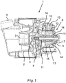
- An in Fig. 1 exemplified pump 1 of a household appliance has a pump housing 2, in which a pump impeller 3 is rotatably arranged.
- the impeller 3 has a plurality of blades 4, which are formed and arranged to suck liquid via an inlet opening 5 axially and eject via an outlet opening 6 radially.
- the pump 1 thus forms a centrifugal pump in the design of a radial pump.
- the impeller 3 is non-rotatably mounted on a motor shaft 7 of a brushless DC wet-running pump drive motor 8.
- the DC wet rotor pump drive motor 8 is disposed in a motor housing 9.
- the motor housing 9 is connected directly to the pump housing 2 in the case of the present embodiment.
- the motor housing 9 together with the pump housing 2 form a structural unit, or even be formed in one piece.
- the DC wet-rotor pump drive motor 8 has an electrically controllable stator winding 10 and a rotor 13 which can be driven in the field of the stator winding 10 and is rotatably mounted by means of the motor shaft 7 in the field between two opposite bearings 11.
- the DC wet-rotor pump drive motor 8 of the illustrated embodiment is designed as a liquid-flowed wet-rotor motor, in which the rotor 13 is mounted within a motor housing 9 in a wet space 16, which is flooded with liquid from the pump housing 2.
- the stator winding 10 is arranged in a dry environment outside of the motor housing 9.
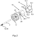
- the rotor 13 essentially comprises the motor shaft 7, a magnet carrier 14 fixed in a rotationally fixed manner on the motor shaft 7, and permanent magnets 15 fixed to the magnet carrier 14 by means of a plastic cage 17 produced by extrusion coating.
- This permanent magnet inner rotor is in Fig. 2 shown in an exploded representation closer.
- the motor shaft 7 has a front shaft end 7a to which the impeller 3 is to be fastened. At this front shaft end 7a, the motor shaft 7 on its outer circumferential wall has a knurling 18, which is designed to fix the impeller 3 rotatably on the motor shaft 7.
- the permanent magnets 15 of the rotor 13 are with their outer surfaces 15.1 in the wet space 16 in the region of an annular gap 12 between the rotor 13 and the stator winding 10 in direct contact with the liquid ( Fig. 1 ).
- the permanent magnets 15 are made of a ferromagnetic material.
- the rotatably mounted in the wet chamber 16 of the pump 1 rotatably mounted rotor 13 has a plurality of evenly distributed over a circumference arranged permanent magnets 15 whose outer surfaces 15.1 are in contact with a located in the annular gap 12 of the electric drive motor 8 liquid of the wet space 16.
- the permanent magnets 15 are held on the magnetic carrier 14 in a frame-like manner by means of a plastic cage 17 produced by encapsulation of the magnetic carrier 14.
- each permanent magnet 15 has at least one around the outer surface 15.1 circumferential chamfer 19, which is filled by the plastic cage 17, whereby the respective permanent magnet 15 form fit is enclosed by the plastic cage 17.
- the magnetic carrier 14 has a polygonal, in particular hexagonal, cross section.
- the magnetic carrier 14 may be formed solid, or be constructed of a stack of a plurality of polygonal, in particular hexagonal stamping sheets in a manner known to those skilled in the art.
- the magnet carrier 14 has a hub 20 in which the motor shaft 7 is received.
- projecting ribs 21 are provided on an inner jacket wall 20.1, which extend in particular in the axial direction.
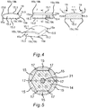
- each permanent magnet 15 has a plane base surface 15.2, which points in the direction of the magnetic carrier 14 and covers the lateral surface 14.1 of the magnetic carrier 14 in a planar manner.
- each permanent magnet 15 has a front end wall 15.3, a rear end wall 15.4, a forward in the direction of rotation of the rotor 13 side wall 15.5 and a trailing side wall 15.6.
- the at least one chamfer 19 according to the invention is formed by the front end wall 15.3, the rear end wall 15.4, the leading side wall 15.5 and the trailing side wall 15.6 each of a vertical position L perpendicular to a base surface 15.2 of the permanent magnet 15 pointing in the direction of the magnetic carrier 14 beveled an angle a inwardly employed position, as in particular in the cross-sectional view of Fig. 4 shown, is formed.
- the angle a can lie in a value range of 1 to 20 degrees, and has a value of approximately 8 degrees, in particular in the illustrated exemplary embodiments.
- the four side edges 15a of the permanent magnet 15, which respectively directly connect the front end wall 15.3, the rear end wall 15.4, the leading side wall 15.5 and the trailing side wall 15.6, are rounded to form a single chamfer 19 encircling the outer surface 15.1 of the permanent magnet 15.
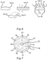
- Both in the first embodiment of according to Fig. 2 to Fig. 5 , as well as in the second embodiment according to Fig. 6 and Fig. 7 is at least one of the front end wall 15.3, the rear end wall 15.4, the leading side wall 15.5 and / or the trailing side wall 15.6 respectively directly to the outer surface 15.1 directly connecting surface edge 15b, in particular the front end wall 15.3 and the rear end wall 15.4 each with the outer surface 15.1 immediately connecting surface edges 15b provided with an additional chamfer 19b.
- the base edges 15c which in each case directly connect the front end wall 15.3, the rear end wall 15.4, the leading side wall 15.5 and the trailing side wall 15.6 with the base 15.2 of the permanent magnet 15 pointing in the direction of the magnetic carrier 14, each have a further chamfer 19c ,
- FIG. 5 shows how the overmolded plastic material of the plastic cage 17, the bevels 19 and 19c of the permanent magnets 15 according to the first embodiment form-fitting manner surrounds to hold the permanent magnets 15 to the magnetic carrier 14.
- the permanent magnets 15 are initially in accordance with their shape analogous to the first embodiment Fig. 2 to Fig. 5 educated.
- the permanent magnets 15 of the second embodiment have additionally stepped surface edges 15d.
- the stepped surface edge 15d is formed by a recess 22 having a width in the axial cross section of the permanent magnet, which is between 10% and 15%, in particular 12% or 13% of the total width of the permanent magnet.
- the stepped surface edge formed by a recess has a minimum height of at least 0.5 millimeter, in particular of at least 0.6 millimeter.
- the at least one, the front end wall 15.3, the rear end wall 15.4, the leading side wall 15.5 and / or the trailing side wall 15.6 each with the pointing in the direction of the magnetic carrier 14 base 15.2 of the permanent magnet 15 directly connecting the bottom edge 15c with provided the further chamfer 19c.
- FIG. 7 shows how the overmolded plastic material of the plastic cage 17, the chamfers 19 and 19c and the stepped recesses 22 of the permanent magnets 15 according to the second embodiment form-fitting manner to hold the permanent magnets 15 to the magnetic carrier 14.
- each permanent magnet 15 has a base 15.2 pointing in the direction of the magnetic carrier 14 and circular in cross-section, and the magnetic carrier 14 has a circular cross-section.
Description
Die Erfindung betrifft einen elektrischen Antriebsmotor für eine Pumpe, aufweisend eine elektrisch ansteuerbare Statorwicklung und einen im Feld der Statorwicklung unter Belassen eines Ringspaltes drehantreibbar gelagerten Rotor, der eine Motorwelle, einen auf der Motorwelle sitzenden Magnetträger und mehrere um wenigstens eine Mantelfläche des Magnetträgers verteilt angeordnete Permanentmagnete aufweist, die jeweils wenigstens eine Außenoberfläche aufweisen und die mittels eines durch Umspritzen des Magnetträgers hergestellten Kunststoffkörpers an dem Magnetträger befestigt sind, wobei der Magnetträger einen polygonförmigen Querschnitt aufweist, wobei jeder Permanentmagnet eine in Richtung des Magnetträgers weisende ebene Grundfläche und eine Außenoberfläche mit einer zylindermantelsegmentförmigen Gestalt aufweist, wobei die Permanentmagnete an ihrer dem Ringspalt zugewandten Außenoberfläche durch den Kunststoffkörper derart form- und/oder kraftschlüssig gehalten sind, dass zumindest ein Teil dieser Außenoberflächen im Ringspalt freiliegt.The invention relates to an electric drive motor for a pump, comprising an electrically controllable stator winding and a rotor in the field of the stator winding while leaving an annular gap rotatably mounted rotor having a motor shaft, a seated on the motor shaft magnet carrier and a plurality of at least one circumferential surface of the magnet carrier distributed permanent magnets each having at least one outer surface and which are secured by means of a plastic body by encapsulating the magnetic carrier on the magnetic carrier, wherein the magnetic carrier has a polygonal cross-section, each permanent magnet pointing in the direction of the magnetic carrier planar base and an outer surface with a cylinder jacket segment-shaped shape has, wherein the permanent magnets on its the annular gap facing outer surface by the plastic body such a positive and / or non-positively held s ind that at least a part of these outer surfaces is exposed in the annular gap.
Die Erfindung betrifft außerdem eine Pumpe mit einem solchen Antriebsmotor und ein Haushaltsgerät, insbesondere eine Geschirrspülmaschine, Waschmaschine oder Trockner, mit einem solchen elektrischen Antriebsmotor und/oder einer solchen Pumpe.The invention also relates to a pump with such a drive motor and a household appliance, in particular a dishwasher, washing machine or dryer, with such an electric drive motor and / or such a pump.
Ein elektrischer Antriebsmotor der eingangs genannten Art ist z.B. aus der
Die
Der Rotor der
Auch beim Rotor der
Beim Rotor der
Auch beim Rotor der
Beim Rotor der
Die
Die
Die Aufgabe der Erfindung ist es, einen elektrischen Antriebsmotor für eine Pumpe, eine Pumpe mit einem solchen elektrischen Antriebsmotor, und ein Haushaltsgerät mit einem solchen elektrischen Antriebsmotor und/oder einer solchen Pumpe zu schaffen, die kostengünstig ist und eine verbesserte Lebensdauer und/oder einen verbesserten Wirkungsgrad aufweist.The object of the invention is to provide an electric drive motor for a pump, a pump with such an electric drive motor, and a household appliance with such an electric drive motor and / or such a pump, which is inexpensive and has an improved life and / or a having improved efficiency.
Die Aufgabe der Erfindung wird gelöst durch einen elektrischen Antriebsmotor mit den Merkmalen des Anspruchs 1:
Erfindungsgemäß weist ein elektrischer Antriebsmotor für eine Pumpe eine elektrisch ansteuerbare Statorwicklung und einen im Feld der Statorwicklung unter Belassen eines Ringspaltes drehantreibbar gelagerten Rotor auf, der eine Motorwelle, einen auf der Motorwelle sitzenden Magnetträger und mehrere um wenigstens eine Mantelfläche des Magnetträgers verteilt angeordnete Permanentmagnete aufweist, die jeweils wenigstens eine Außenoberfläche aufweisen und die mittels eines durch Umspritzen des Magnetträgers hergestellten Kunststoffkörpers an dem Magnetträger befestigt sind, wobei der Magnetträger einen polygonförmigen Querschnitt aufweist, wobei jeder Permanentmagnet eine in Richtung des Magnetträgers weisende ebene Grundfläche und eine Außenoberfläche mit einer zylindermantelsegmentförmigen Gestalt aufweist, und wobei die Permanentmagnete an ihrer dem Ringspalt zugewandten Außenoberfläche durch den Kunststoffkörper derart form- und/oder kraftschlüssig gehalten sind, dass zumindest ein Teil dieser Außenoberflächen im Ringspalt freiliegt. Erfindungsgemäß ist der Magnetträger aus einem ferromagnetischen Chromstahl, nämlich aus einem ferritischen oder martensitischen Chromstahl mit wenigstens 10,5% Chromanteil hergestellt.The object of the invention is achieved by an electric drive motor with the features of claim 1:
According to the invention, an electric drive motor for a pump has an electrically controllable stator winding and a rotor rotatably mounted in the field of the stator winding while leaving an annular gap, which has a motor shaft, a magnet carrier seated on the motor shaft and a plurality of permanent magnets distributed around at least one lateral surface of the magnet carrier, each having at least one outer surface and which are fixed by means of a plastic body produced by encapsulation of the magnetic carrier on the magnetic carrier, wherein the magnetic carrier has a polygonal cross-section, each permanent magnet having a pointing in the direction of the magnetic carrier planar base and an outer surface with a cylinder jacket segment-shaped shape, and wherein the permanent magnets are held in such a form and / or non-positively by the plastic body at its outer surface facing the annular gap, that at least part of these outer surfaces is exposed in the annular gap. According to the invention the magnetic carrier made of a ferromagnetic chromium steel, namely made of a ferritic or martensitic chromium steel with at least 10.5% chromium content.
Insbesondere kann der aus einem ferromagnetischen Chromstahl hergestellte Magnetträger einen hexagonalen Querschnitt aufweisen.In particular, the magnetic carrier made of a ferromagnetic chrome steel may have a hexagonal cross-section.
Insbesondere kann der Kunststoffkörper als ein Kunststoffkäfig ausgebildet sein, der den jeweils freiliegenden Teil der Außenoberfläche jeden Permanentmagnets form- und/oder kraftschlüssig einfasst.In particular, the plastic body may be formed as a plastic cage, the form-fitting and / or frictionally engages the respectively exposed part of the outer surface of each permanent magnet.
Beispielsweise im Falle eines Nassläufermotors sind dabei die dem Ringspalt zuweisenden Außenoberflächen jeden Permanentmagnets von der in dem Ringspalt vorhandenen Flüssigkeit benetzt. Beispielsweise im Falle eines Trockenläufermotors sind dabei die dem Ringspalt zuweisenden Außenoberflächen jeden Permanentmagnets von der in dem Ringspalt vorhandenen Luft oder Gas umspült.For example, in the case of a wet-rotor motor, the outer surfaces of each permanent magnet facing the annular gap are wetted by the liquid present in the annular gap. For example, in the case of a dry-running motor, the outer surfaces of each permanent magnet facing the annular gap are surrounded by the air or gas present in the annular gap.
Der durch das Umspritzen gebildete Kunststoffkäfig kann eine Umfangsfläche aufweisen, die sich mit den Außenoberflächen der Permanentmagnete, die dem Ringspalt zugewandt sind, zu einer zylindrischen Mantelwand ergänzen, welche eine äußere Mantelwand des Rotors bildet. Die Außenoberflächen der Permanentmagnete können sich insoweit bündig an die Umfangsfläche des Kunststoffkäfigs anschließen, insbesondere dabei auf demselben Radius liegen.The plastic cage formed by the encapsulation may have a peripheral surface, which complement with the outer surfaces of the permanent magnets, which face the annular gap, to form a cylindrical jacket wall, which forms an outer jacket wall of the rotor. The outer surfaces of the permanent magnets can so far flush with the peripheral surface of the plastic cage, in particular while lying on the same radius.
Die Permanentmagnete können mittels eines als Kunststoffkäfig ausgebildeten Kunststoffkörpers an dem Magnetträger befestigt sein, der unter Freilassen jeweils eines dem Ringspalt zuweisenden Teils der Außenoberflächen, jeden Permanentmagnet rahmenartig form- und/oder kraftschlüssig einfasst.The permanent magnets can be attached to the magnet carrier by means of a plastic cage designed as a plastic body, which encloses each permanent magnet in a form-fitting and / or non-positively locking manner, each freeing a part of the outer surfaces that points to the annular gap.
Um jeden Permanentmagnet durch den Kunststoffkörper, insbesondere durch den Kunststoffkäfig form- und/oder kraftschlüssig, insbesondere rahmenartig einfassen zu können, kann jeder Permanentmagnet wenigstens eine Fase aufweisen, insbesondere wenigstens eine um seine Außenoberfläche umlaufende Fase aufweisen, die von dem Kunststoffkörper, insbesondere von dem Kunststoffkäfig form- und/oder kraftschlüssig eingefasst ist.To each permanent magnet by the plastic body, in particular by the plastic cage form and / or frictionally, in particular frame-like, each permanent magnet may have at least one chamfer, in particular at least one circumferential around its outer surface chamfer, of the Plastic body, in particular of the plastic cage is framed form and / or non-positively.
Damit das von der elektrisch ansteuerbaren Statorwicklung erzeugte Drehfeld mit hohem Wirkungsgrad auf den Rotor einwirken kann, wird erfindungsgemäß die Breite des Ringspaltes so weit wie möglich reduziert. Dies erfolgt erfindungsgemäß dadurch, dass der Rotor derart aufgebaut ist, dass die Außenoberflächen der Permanentmagnete unmittelbar an den Ringspalt angrenzen. Da bei einer solchen Ausbildung des Rotors beispielsweise kein Stahltopf vorhanden, der die Permanentmagnete über ihren Umfang vollständig einkapselt und die Permanentmagnete auch nicht vollständig von Kunststoffmaterial eingeschlossen werden, kann der Abstand der Außenoberflächen der Permanentmagnete zu der Statorwicklung deutlich reduziert werden, wodurch sich der Wirkungsgrad des elektrischen Antriebsmotors erhöht. Auch wenn eine solche Verbesserung des Wirkungsgrades auch bei Verwendung von Permanentmagnete aus einem Seltene Erden Material eintritt, so ist eine Ausbildung des Rotors, bei dem die Außenoberflächen der Permanentmagnete unmittelbar an den Ringspalt angrenzen, besonders dann sinnvoll, wenn statt teuren Seltene Erden Magnete vorzugsweise ferritische, insbesondere hartferritische Permanentmagnete verwendet werden, welche eine deutlich geringere magnetische Permeabilität aufweisen als Seltene Erden Magnete. Hinsichtlich einer Kosteneinsparung haben jedoch ferritische, insbesondere hartferritische Permanentmagnete Vorteile.So that the rotating field generated by the electrically controllable stator winding can act with high efficiency on the rotor, according to the invention, the width of the annular gap is reduced as much as possible. This is done according to the invention in that the rotor is constructed such that the outer surfaces of the permanent magnets directly adjoin the annular gap. For example, since in such a design of the rotor no steel pot is present, which completely encapsulates the permanent magnets over its circumference and the permanent magnets are not completely enclosed by plastic material, the distance between the outer surfaces of the permanent magnets can be significantly reduced to the stator winding, whereby the efficiency of the increased electric drive motor. Even if such an improvement of the efficiency occurs even when using permanent magnets made of a rare earth material, so is an embodiment of the rotor, in which the outer surfaces of the permanent magnets directly adjacent to the annular gap, especially useful if instead of expensive rare earth magnets preferably ferritic , in particular hard-ferromagnetic permanent magnets are used, which have a significantly lower magnetic permeability than rare earth magnets. However, ferritic, especially hard-ferrite permanent magnets have advantages in terms of cost savings.
Indem jeder Permanentmagnet eine an den Ringspalt angrenzende Außenoberfläche aufweist, welche durch wenigstens eine um die Außenoberfläche umlaufende Fase begrenzt ist und die wenigstens eine Fase von dem Kunststoffkäfig formschlüssig eingefasst ist, kann eine möglichst große Fläche der Außenoberfläche der Permanentmagnete unmittelbar an den Ringspalt angrenzen, wobei durch die erfindungsgemäß um die Außenoberfläche umlaufende wenigstens eine Fase die Permanentmagnete durch den Kunststoffkäfig formschlüssig an dem Magnetträger gehalten werden, ohne dass es eines separaten Stahltopfes oder eines die Permanentmagnete vollständig einschließenden Kunststoffkäfigs bedarf, wodurch die Permanentmagnete zwangsläufig in einem größeren Abstand von der Statorwicklung anzuordnen wären.Since each permanent magnet has an outer surface adjoining the annular gap, which is delimited by at least one bevel surrounding the outer surface and which is frictionally enclosed by the plastic cage, the largest possible surface area of the outer surface of the permanent magnets can directly adjoin the annular gap by the inventively around the outer surface at least one chamfer the permanent magnets are held by the plastic cage positively on the magnetic carrier, without the need for a separate steel pot or a permanent magnets completely enclosing plastic cage, whereby the permanent magnets would inevitably be arranged at a greater distance from the stator winding ,
Alle Permanentmagnete eines Rotors sind vorzugsweise identisch ausgebildet. Sie können insbesondere in gleichen Abständen voneinander entfernt über den Umfang des Magnetträgers verteilt angeordnet sein. Die Außenoberflächen der Permanentmagnete weisen eine zylindermantelsegmentförmige Gestalt auf. Die über den Umfang des Magnetträgers verteilt angeordneten Permanentmagnete ergänzen sich in ihren Außenoberflächen insoweit zu einer im Wesentlichen zylindrischen Außenfläche, die nur durch geringfügige Stege des Kunststoffkäfigs unterbrochen sind.All permanent magnets of a rotor are preferably identical. In particular, they can be distributed at equal distances from one another over the circumference of the magnet carrier. The outer surfaces of the permanent magnets have a cylinder jacket segment-shaped shape. The distributed over the circumference of the magnetic carrier permanent magnets complement each other in their outer surfaces so far to a substantially cylindrical outer surface, which are interrupted only by slight webs of the plastic cage.
Dadurch, dass jeder Permanentmagnet wenigstens eine umlaufende Fase aufweist, können die um den Magnetträger angeordneten Permanentmagnete formschlüssig durch den umspritzten Kunststoffkäfig an dem Magnetträger derart befestigt werden, dass der Kunststoffkäfig zusammen mit den Permanentmagneten eine glattwandige zylindrische Mantelwand des Rotors bildet, die Fenster ausbildet, welche unmittelbar von den Außenoberflächen der Permanentmagnete gebildet werden.Characterized in that each permanent magnet has at least one circumferential chamfer, which are arranged around the magnet carrier permanent magnets can be positively secured by the overmolded plastic cage on the magnet carrier such that the plastic cage together with the permanent magnet forms a smooth-walled cylindrical shell wall of the rotor, which forms windows be formed directly from the outer surfaces of the permanent magnets.
So kann jeder Permanentmagnet eine vordere Stirnwand, eine hintere Stirnwand, eine in Drehrichtung des Rotors vorauseilende Seitenwand und eine nacheilende Seitenwand aufweisen, wobei die wenigstens eine Fase dadurch gebildet wird, dass die vordere Stirnwand, die hintere Stirnwand, die vorauseilende Seitenwand und die nacheilende Seitenwand jeweils aus einer zu einer in Richtung des Magnetträgers weisenden Grundfläche des Permanentmagneten senkrechten Lage um einen Winkel nach innen angestellten Lage abgeschrägt ausgebildet sind.Thus, each permanent magnet may include a front end wall, a rear end wall, a sidewall advancing in the direction of rotation of the rotor, and a trailing sidewall, wherein the at least one chamfer is formed by the front end wall, the rear end wall, the leading sidewall, and the trailing sidewall in each case from one to a pointing in the direction of the magnetic carrier surface of the permanent magnet perpendicular position beveled by an angle inwardly employed position.
Die vordere Stirnwand des Permanentmagneten ist insoweit eine Seitenwand des Permanentmagneten, die in einer Einbaulage des Permanentmagneten an dem Rotor in Richtung des vorderen Wellenendes der Motorwelle weist, welches Wellenende insbesondere im Falle einer Pumpe das Pumpenrad trägt. Demgemäß ist die hintere Stirnwand des Permanentmagneten eine der vorderen Stirnwand gegenüberliegende Seitenwand des Permanentmagneten, die in einer Einbaulage des Permanentmagneten an dem Rotor von dem vorderen Wellenendes der Motorwelle weg weist. Mit seiner Grundfläche liegt der jeweilige Permanentmagnet an einer Mantelfläche des Magnetträgers insbesondere berührend an.The front end wall of the permanent magnet is so far a side wall of the permanent magnet, which points in an installed position of the permanent magnet on the rotor in the direction of the front shaft end of the motor shaft, which end of the shaft carries in particular in the case of a pump impeller. Accordingly, the rear end wall of the permanent magnet is a side wall of the permanent magnet opposed to the front end wall, which faces away from the front shaft end of the motor shaft in an installed position of the permanent magnet on the rotor. With its base surface of the respective permanent magnet is applied to a lateral surface of the magnetic carrier in particular touching.
Die Eigenschaft, dass die vordere Stirnwand, die hintere Stirnwand, die vorauseilende Seitenwand und die nacheilende Seitenwand jeweils aus einer zu einer in Richtung des Magnetträgers weisenden Grundfläche des Permanentmagneten senkrechten Lage um einen Winkel nach innen angestellten Lage abgeschrägt ausgebildet sind, kann insoweit anders ausgedrückt bedeuten, dass die Permanentmagnete eine pyramidenstumpfartige Gestalt aufweisen, wobei die größere Grundfläche des Pyramidenstumpfes durch die Grundfläche des Permanentmagneten gebildet wird und die kleinere Deckfläche des Pyramidenstumpfes durch die Außenoberfläche des Permanentmagneten gebildet wird und insbesondere das durch die gedachte Spitze laufende Lot die Grundfläche schneidet. Die Grundfläche kann dabei insbesondere rechteckig oder quadratisch sein. Die Höhe des Permanentmagneten ist dabei um ein Vielfaches kleiner als die Länge oder Breite der Grundfläche.The property that the front end wall, the rear end wall, the leading side wall and the trailing side wall are each bevelled beveled from a position perpendicular to a pointing in the direction of the magnetic carrier base surface of the permanent magnet position by an angle inwardly salaried position, in other words meaning different in that the permanent magnets have a truncated pyramidal shape, the larger base area of the truncated pyramid being formed by the base area of the permanent magnet and the smaller top area of the truncated pyramid being formed by the outer surface of the permanent magnet and in particular the perpendicular passing through the imaginary tip intersecting the base area. The base can be rectangular or square in particular. The height of the permanent magnet is smaller by a multiple than the length or width of the base.
Der Winkel, also der Neigungswinkel der Seitenflächen des pyramidenstumpfartigen Permanentmagneten gegenüber seiner Grundfläche nach innen kann in einem Wertebereich von 1 bis 20 Grad liegt, insbesondere einen Wert von 8 Grad aufweist.The angle, that is, the angle of inclination of the side surfaces of the truncated pyramidal permanent magnet with respect to its base inwardly can be in a range of values of 1 to 20 degrees, in particular has a value of 8 degrees.
Unter einem solchen Winkel wird ein besonders ausgewogenes Verhältnis zwischen der Anforderung an einer möglichst großen, magnetisch wirksamen Außenoberfläche des Permanentmagneten und eines möglichst sicheren formschlüssigen Umgreifens der Permanentmagnete durch den Kunststoffkäfig zur sicheren Fixierung an dem Magnetträger.At such an angle, a particularly balanced relationship between the requirement for the largest possible, magnetically effective outer surface of the permanent magnet and a safe as possible positive gripping the permanent magnets through the plastic cage for secure fixation to the magnet carrier.
Generell können die die vordere Stirnwand, die hintere Stirnwand, die vorauseilende Seitenwand und die nacheilende Seitenwand jeweils unmittelbar verbindenden Seitenkanten zur Bildung einer einzigen, kantenlos um die Außenoberfläche des Permanentmagneten umlaufende Fase abgerundet ausgebildet sind. Es kann also statt vier geraden Kantenfasen, die an vier Ecken aufeinandertreffen, durch eine Abrundung der Ecken insoweit eine einzige umlaufende Fase gebildet werden, welche den Permanentmagneten eckenlos umläuft. Eine solche Fase kann in günstiger Weise gefertigt werden, kann Materialspannungen im Permanentmagneten reduzieren und eine Fixierung durch den umspritzten Kunststoffkäfig begünstigen.In general, the front end wall, the rear end wall, the leading sidewall and the trailing sidewall each directly connecting side edges to form a single, edgeless around the outer surface of the permanent magnet circumferential bevel are rounded. Thus, instead of four straight edge chamfers, which meet at four corners, by rounding off the corners a single circumferential chamfer can be formed, which runs around the permanent magnet without corners. Such a chamfer can be made in a favorable manner, can reduce material stresses in the permanent magnet and favor a fixation by the overmolded plastic cage.
In einer abgewandelten Ausführungsform können wenigstens eine die vordere Stirnwand, die hintere Stirnwand, die vorauseilende Seitenwand und/oder die nacheilende Seitenwand jeweils mit der Außenoberfläche unmittelbar verbindende Oberflächenkante, insbesondere die die vordere Stirnwand und die hintere Stirnwand jeweils mit der Außenoberfläche unmittelbar verbindende Oberflächenkanten mit einer zusätzlichen Fase versehen sein.In a modified embodiment, at least one of the front end wall, the rear end wall, the leading sidewall and / or the trailing sidewall respectively directly to the outer surface directly connecting surface edge, in particular the front end wall and the rear end wall in each case directly to the outer surface surface edges connecting with a be provided additional chamfer.
In einer weiteren Ausführungsform können alternativ oder ergänzend zu einer anderen Ausführungsform wenigstens eine die vordere Stirnwand, die hintere Stirnwand, die vorauseilende Seitenwand und/oder die nacheilende Seitenwand jeweils mit der Außenoberfläche unmittelbar verbindende Oberflächenkante, insbesondere die die vorauseilende Seitenwand und die nacheilende Seitenwand jeweils mit der Außenoberfläche unmittelbar verbindende Oberflächenkanten gestuft ausgebildet sein.In a further embodiment, alternatively or in addition to another embodiment, at least one of the front end wall, the rear end wall, the leading sidewall and / or the trailing sidewall respectively directly to the outer surface directly connecting surface edge, in particular the leading sidewall and the trailing sidewall each with the outer surface directly connecting surface edges may be stepped.
Durch eine oder mehrere zusätzlicher Fasen und/oder Stufen kann das Kunststoffmaterial des Kunststoffkäfigs die Permanentmagnete besonders gut umfassen bzw. einschließen. Dabei kann insbesondere sichergestellt sein, dass im Bereich der Fasen und/oder der Stufen das Kunststoffmaterial eine Mindestschichtdicke von ca. 0,5 bis 0,7, insbesondere 0,6 Millimeter aufweist. So kann sichergestellt sein, dass alle Fasen und/oder Stufen beim Umspritzen vollständig mit Kunststoffmaterial ausgefüllt werden können und auch nach einem Aushärten des Kunststoffmaterials der Kunststoffkäfig an seinen Rändern zur Außenoberfläche der Permanentmagnete hin ausreichend formstabil und/oder resistent gegen Abnutzung, insbesondere Abschälen ist.By one or more additional chamfers and / or steps, the plastic material of the plastic cage can include or include the permanent magnets particularly well. In this case, it can be ensured in particular that in the region of the chamfers and / or the steps, the plastic material has a minimum layer thickness of about 0.5 to 0.7, in particular 0.6 millimeters. Thus, it can be ensured that all chamfers and / or steps during encapsulation can be completely filled with plastic material and even after curing of the plastic material of the plastic cage at its edges to the outer surface of the permanent magnets out sufficiently dimensionally stable and / or resistant to wear, especially peeling.
In den jeweiligen Ausführungsformen kann die gestuft ausgebildete Oberflächenkante durch eine Ausnehmung gebildet werden, die im axialen Querschnitt des Permanentmagneten eine Breite aufweist, die zwischen 10% und 15%, insbesondere 12% oder 13% der Gesamtbreite des Permanentmagneten beträgt.In the respective embodiments, the stepped surface edge can be formed by a recess having a width in the axial cross section of the permanent magnet, which is between 10% and 15%, in particular 12% or 13% of the total width of the permanent magnet.
Die gestuft ausgebildete Oberflächenkante kann durch eine Ausnehmung gebildet werden, die im axialen Querschnitt des Permanentmagneten eine Mindesthöhe von wenigstens 0,5 Millimeter, insbesondere von wenigstens 0,6 Millimeter aufweist.The stepped surface edge formed may be formed by a recess having a minimum height of at least 0.5 millimeters, in particular of at least 0.6 millimeters in the axial cross section of the permanent magnet.
In einer weiter abgewandelten Ausführungsform kann wenigstens eine die vordere Stirnwand, die hintere Stirnwand, die vorauseilende Seitenwand und/oder die nacheilende Seitenwand jeweils mit der in Richtung des Magnetträgers weisenden Grundfläche des Permanentmagneten unmittelbar verbindende Grundkante mit einer weiteren Fase versehen sein.In a further modified embodiment, at least one of the front end wall, the rear end wall, the leading side wall and / or the trailing side wall in each case with the pointing in the direction of the magnetic carrier base surface of the permanent magnet directly connecting the bottom edge may be provided with a further chamfer.
Erfindungsgemäß weist jeder Permanentmagnet eine in Richtung des Magnetträgers weisende ebene Grundfläche auf und der Magnetträger weist einen polygonförmigen, insbesondere hexagonalen Querschnitt auf.According to the invention, each permanent magnet has a flat base surface pointing in the direction of the magnet carrier, and the magnet carrier has a polygonal, in particular hexagonal, cross section.
Ergänzend kann in allen Ausführungsformen der Magnetträger eine Nabe zur Aufnahme der Motorwelle aufweisen, deren innere Mantelwand mit vorspringenden Rippen versehen ist, die sich insbesondere in axialer Richtung erstrecken. Die Rippen bewirken eine besonders zuverlässige Befestigung des Magnetträgers auf der Motorwelle.In addition, in all embodiments of the magnetic carrier having a hub for receiving the motor shaft, the inner jacket wall is provided with projecting ribs, which extend in particular in the axial direction. The ribs cause a particularly reliable attachment of the magnet carrier on the motor shaft.
Die Erfindung betrifft auch eine Pumpe, aufweisend einen elektrischen Antriebsmotor wie erfindungsgemäß beschrieben, bei welcher der Rotor in einem Nassraum der Pumpe drehantreibbar gelagert ist und die Außenoberflächen der Permanentmagnete in Kontakt zu einer in dem Ringspalt des elektrischen Antriebsmotors befindlichen Flüssigkeit des Nassraumes stehen.The invention also relates to a pump, comprising an electric drive motor as described according to the invention, in which the rotor is rotatably mounted in a wet chamber of the pump and the outer surfaces of the permanent magnets are in contact with a located in the annular gap of the electric drive motor fluid of the wet space.
Die im Nassraum befindliche Flüssigkeit dient unter anderem der Kühlung und/oder Schmierung des Rotors bzw. der Lager des Rotors. Um einen hohen elektromagnetischen Wirkungsgrad zu erreichen, wird die äußere Mantelwand des Rotors, d.h. des Rotormagneten konstruktiv möglichst nahe an die Statorwicklung herangeführt. Dies hat zur Folge, dass zwischen Rotor bzw. Rotormagnet und der Innenwand des Nassraums nur ein sehr geringer Spalt vorhanden ist, der insbesondere während einer Rotation des Rotors nur relativ wenig von der Flüssigkeit durchströmt wird. Insoweit kann ein von einem Flüssigkeitszulauf abgewandter Nassraumbereich nur sehr schwer allein über diesen Spalt durchspült werden. Insbesondere kann in einem solchen hinteren, d.h. dem Pumpenrad abgewandten Nassraumbereich sich in unerwünschter Weise Luft- und/oder Dampfblasen ansammeln. Aufgrund der Rotation des Rotors sammeln sich tendenziell Luft- und/oder Dampfblasen im achsnahen Zentrum des Nassraumes nahe der Motorwelle und nicht in einem äußeren Umfang nahe des Spaltes. Mittels wenigstens eines im Magnetträger angeordneten Strömungskanals kann die Flüssigkeit besonders gut zirkulieren und insbesondere können Luft- und/oder Dampfblasen herausgeführt werden, so dass keine Gefahr besteht, dass die Lager des Rotors trockenlaufen, was die Lebensdauer der Pumpe und den Wirkungsgrad der Pumpe reduzieren würde. Durch ein Abführen von Luft- und/oder Dampfblasen läuft der Antriebsmotor und damit auch die Pumpe außerdem leiser.Among other things, the liquid in the wet space serves to cool and / or lubricate the rotor or the bearings of the rotor. In order to achieve a high electromagnetic efficiency, the outer jacket wall of the rotor, ie the rotor magnet is constructively brought as close as possible to the stator winding. This has the consequence that only a very small gap is present between the rotor or rotor magnet and the inner wall of the wet space, which is traversed by the liquid only relatively little, in particular during a rotation of the rotor. In that regard, a remote from a liquid inlet wet space area is very difficult to be flushed through this gap alone. In particular, in such a rear, ie, the pump chamber facing away from the wet chamber area can accumulate undesirable air and / or vapor bubbles. Due to the rotation of the rotor, air bubbles and / or vapor bubbles tend to accumulate in the near-center of the wet space the motor shaft and not in an outer circumference near the gap. By means of at least one flow channel arranged in the magnet carrier, the liquid can circulate particularly well and in particular air and / or vapor bubbles can be led out so that there is no danger that the bearings of the rotor run dry, which would reduce the life of the pump and the efficiency of the pump , By discharging air and / or vapor bubbles of the drive motor and thus also the pump runs quieter.
Die Pumpe kann ein von dem elektrischen Antriebsmotor antreibbares Pumpenrad aufweisen und die Motorwelle des elektrischen Antriebsmotors ergänzend eine Rändelung aufweisen, auf welcher das Pumpenrad befestigt ist. Damit wird eine besonders zuverlässige Befestigung des Pumpenrads an der Motorwelle erreicht, was die Lebensdauer der Pumpe erhöhen kann.The pump may have an impeller driven by the electric drive motor and the motor shaft of the electric drive motor additionally have a knurling on which the impeller is mounted. Thus, a particularly reliable attachment of the impeller to the motor shaft is achieved, which can increase the life of the pump.
Die folgenden Merkmale können einzeln oder in Kombination zueinander in unterschiedlichen Ausführungsformen Anwendung finden: Generell kann es sich bei dem Antriebsmotor um einen bürstenlosen Gleichstrom-Nassläufer-Pumpenantriebsmotor handeln. Der Rotor kann generell als ein Permanentmagnet-Innenrotor ausgebildet sein. Ganz allgemein kann der Gleichstrom-Pumpenantriebsmotor generell als ein von Flüssigkeit durchströmter Nassläufermotor ausgebildet sein und der Permanentmagnet-Rotor dabei in unmittelbarem Kontakt zur Flüssigkeit stehen. Der Magnetträger kann in allen Ausführungen entweder einstückig ausgebildet sein oder aus einem Blechpaket von mehreren übereinander gestapelten, miteinander verbundenen Blechplatten hergestellt sein.The following features may be used individually or in combination in different embodiments: Generally, the drive motor may be a brushless DC wet-running pump drive motor. The rotor may generally be formed as a permanent magnet inner rotor. In general, the DC pump drive motor can generally be designed as a liquid-flow wet-running motor and the permanent-magnet rotor can be in direct contact with the liquid. The magnetic carrier may be formed integrally in all versions or be made of a laminated core of several stacked, interconnected metal plates.
Der Magnetträger ist erfindungsgemäß aus einem ferromagnetischen Chromstahl hergestellt. Anders ausgedrückt besteht der Magnetträger aus Edelstahl.The magnetic carrier according to the invention is made of a ferromagnetic chromium steel. In other words, the magnetic carrier is made of stainless steel.
Der Magnetträger ist erfindungsgemäß aus einem ferritischen oder martensitischen Chromstahl mit wenigstens 10,5% Chromanteil hergestellt. Der Magnetträger kann aus einem nickelfreien Chromstahl hergestellt sein.The magnetic carrier according to the invention is made of a ferritic or martensitic chromium steel with at least 10.5% chromium content. The magnetic carrier can be made of a nickel-free chrome steel.
Beispielsweise kann der Magnetträger aus einem Chromstahl mit 16% bis 18% Chromanteil, insbesondere ca. 17% Chromanteil, insbesondere der Werkstoffnummer 1.4016 gemäß EN 10027-2 (X6Cr17, AISI 430) hergestellt sein.For example, the magnetic carrier from a chromium steel with 16% to 18% chromium, in particular about 17% chromium, in particular the material number 1.4016 according to EN 10027-2 (X6Cr17, AISI 430) to be made.
Ergänzend zu einem Magnetträger aus einem ferromagnetischen Chromstahl kann auch die Motorwelle aus einem Chromstahl hergestellt sein. Anders ausgedrückt kann die Motorwelle aus Edelstahl bestehen. Die Motorwelle kann aus einem härtbaren, insbesondere austenitischen oder martensitischen Chromstahl hergestellt sein.In addition to a magnetic carrier made of ferromagnetic chrome steel, the motor shaft can also be made of chrome steel. In other words, the motor shaft may be made of stainless steel. The motor shaft may be made of a hardenable, in particular austenitic or martensitic chromium steel.
Beispielsweise kann die Motorwelle aus einem Chromstahl mit 15% bis 17% Chromanteil, insbesondere ca. 16% Chromanteil und 3% bis 5% Nickelanteil, insbesondere ca. 4% Nickelanteil, insbesondere der Werkstoffnummer 1.4542 gemäß EN 10027-2 (X5CrNiCuNb16-4, AISI 630) hergestellt sein.For example, the motor shaft of a chromium steel with 15% to 17% chromium content, in particular about 16% chromium content and 3% to 5% nickel content, in particular about 4% nickel content, in particular the material number 1.4542 according to EN 10027-2 (X5CrNiCuNb16-4, AISI 630).
Die Erfindung betrifft außerdem ein Haushaltsgerät, insbesondere eine Geschirrspülmaschine, eine Waschmaschine oder einen Trockner, das einen erfindungsgemäßen elektrischen Antriebsmotor und/oder eine erfindungsgemäße Pumpe, wie beschrieben, aufweist.The invention also relates to a household appliance, in particular a dishwasher, a washing machine or a dryer, which has an electric drive motor according to the invention and / or a pump according to the invention, as described.
Verschiedene konkrete Ausführungsbeispiele erfindungsgemäßer elektrischer Antriebsmotoren sind in der nachfolgenden Beschreibung unter Bezugnahme auf die beigefügten Figuren näher erläutert. Konkrete Merkmale dieser Ausführungsbeispiele können unabhängig davon, in welchem konkreten Zusammenhang sie erwähnt sind, gegebenenfalls auch einzeln oder in Kombination betrachtet, allgemeine Merkmale der Erfindung darstellen.Various concrete embodiments of electric drive motors according to the invention are explained in more detail in the following description with reference to the accompanying figures. Concrete features of these embodiments, regardless of the specific context in which they are mentioned, if appropriate also individually or in combination, represent general features of the invention.
Es zeigen:
- Fig. 1
- eine Querschnittsansicht einer beispielhaften Pumpe eines Haushaltsgeräts mit einem erfindungsgemäßen elektrischen Antriebsmotor in Form eines Nassläufer-Pumpenantriebsmotors,
- Fig. 2
- eine perspektivische Explosionsdarstellung einer ersten Ausführungsform eines Permanentmagnet-Innenrotors des erfindungsgemäßen elektrischen Antriebsmotors;
- Fig. 3
- eine perspektivische Ansicht des Permanentmagnet-Innenrotors gemäß
Fig. 2 in einem zusammengesetzten Zustand; - Fig. 4
- einen einzelnen Permanentmagneten des elektrischen Antriebsmotors nach der ersten Ausführungsform gemäß
Fig. 2 undFig. 3 in einer Frontansicht, einer Seitenansicht, einer Querschnittsansicht und in einer perspektivischen Darstellung; - Fig. 5
- eine Querschnittsansicht des zusammengesetzten Permanentmagnet-Innenrotors der ersten Ausführungsform gemäß
Fig. 3 ; - Fig. 6
- einen einzelnen Permanentmagneten des elektrischen Antriebsmotors nach einer zweiten Ausführungsform in einer Frontansicht, einer Seitenansicht, einer Querschnittsansicht und in einer perspektivischen Darstellung;
- Fig. 7
- eine Querschnittsansicht des zusammengesetzten Permanentmagnet-Innenrotors der zweiten Ausführungsform gemäß
Fig. 6 ; und - Fig. 8
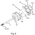
- eine perspektivische Explosionsdarstellung einer nicht zur Erfindung gehörenden Ausführungsform eines Permanentmagnet-Innenrotors eines elektrischen Antriebsmotors.
- Fig. 1
- a cross-sectional view of an exemplary pump of a household appliance with an electric drive motor according to the invention in the form of a wet rotor pump drive motor,
- Fig. 2
- an exploded perspective view of a first embodiment of a permanent magnet inner rotor of the electric drive motor according to the invention;
- Fig. 3
- a perspective view of the permanent magnet inner rotor according to
Fig. 2 in an assembled state; - Fig. 4
- a single permanent magnet of the electric drive motor according to the first embodiment according to
Fig. 2 andFig. 3 in a front view, a side view, a cross-sectional view and in a perspective view; - Fig. 5
- a cross-sectional view of the composite permanent magnet inner rotor according to the first embodiment
Fig. 3 ; - Fig. 6
- a single permanent magnet of the electric drive motor according to a second embodiment in a front view, a side view, a cross-sectional view and in a perspective view;
- Fig. 7
- a cross-sectional view of the composite permanent magnet inner rotor according to the second embodiment
Fig. 6 ; and - Fig. 8
- an exploded perspective view of a not belonging to the invention embodiment of a permanent magnet inner rotor of an electric drive motor.
Eine in
Der Gleichstrom-Nassläufer-Pumpenantriebsmotor 8 ist in einem Motorgehäuse 9 angeordnet. Das Motorgehäuse 9 ist im Falle des vorliegenden Ausführungsbeispiels unmittelbar mit dem Pumpengehäuse 2 verbunden. Gegebenenfalls kann das Motorgehäuse 9 zusammen mit dem Pumpengehäuse 2 eine Baueinheit bilden, oder sogar einteilig ausgebildet sein. Der Gleichstrom-Nassläufer-Pumpenantriebsmotor 8 weist einer elektrisch ansteuerbare Statorwicklung 10 und einen im Feld der Statorwicklung 10 antreibbaren und mittels der Motorwelle 7 im Feld zwischen zwei gegenüberliegenden Lagern 11 drehbar gelagerten Rotor 13 auf.The DC wet rotor
Der Gleichstrom-Nassläufer-Pumpenantriebsmotor 8 des dargestellten Ausführungsbeispiels ist als ein von Flüssigkeit durchströmter Nassläufermotor ausgebildet, bei dem der Rotor 13 innerhalb eines Motorgehäuses 9 in einem Nassraum 16 gelagert ist, der von Flüssigkeit aus dem Pumpengehäuse 2 durchflutet ist. Die Statorwicklung 10 ist dabei in trockener Umgebung außerhalb des Motorgehäuses 9 angeordnet.The DC wet-rotor
In dargestellten Ausführungsbeispiel weist der Rotor 13 im Wesentlichen die Motorwelle 7, einen auf der Motorwelle 7 drehfest befestigten Magnetträger 14 und an dem Magnetträger 14 mittels eines durch Umspritzen hergestellten Kunststoffkäfigs 17 fixierte Permanentmagnete 15 auf.In the illustrated embodiment, the
Dieser Permanentmagnet-Innenrotor ist in
Die Motorwelle 7 weist ein vorderes Wellenende 7a auf, an dem das Pumpenrad 3 zu befestigen ist. An diesem vorderen Wellenende 7a weist die Motorwelle 7 an ihrer Außenmantelwand eine Rändelung 18 auf, die ausgebildet ist, das Pumpenrad 3 drehfest auf der Motorwelle 7 zu fixieren.The
Die Permanentmagnete 15 des Rotors 13 stehen mit ihren Außenoberflächen 15.1 im Nassraum 16 im Bereich eines Ringspaltes 12 zwischen dem Rotor 13 und der Statorwicklung 10 in unmittelbarem Kontakt zur Flüssigkeit (
Der in dem Nassraum 16 der Pumpe 1 drehantreibbar gelagerte Rotor 13 weist mehrere gleichmäßig über einen Umfang verteilt angeordnete Permanentmagnete 15 auf, deren Außenoberflächen 15.1 in Kontakt zu einer in dem Ringspalt 12 des elektrischen Antriebsmotors 8 befindlichen Flüssigkeit des Nassraumes 16 stehen.The rotatably mounted in the
Um die mehreren an wenigstens einer Mantelfläche 14.1 des Magnetträgers 14 verteilt angeordneten Permanentmagnete 15 an dem Magnetträger 14 zu befestigen, werden die Permanentmagnete 15 randseitig rahmenartig mittels eines durch Umspritzen des Magnetträgers 14 hergestellten Kunststoffkäfigs 17 formschlüssig an dem Magnetträger 14 festgehalten.In order to fix the plurality of
Damit der durch Umspritzen des Magnetträgers 14 hergestellte Kunststoffkäfig 17 die Permanentmagnete 15 formschlüssig an dem Magnetträger 14 halten kann, weist jeder Permanentmagnet 15 wenigstens eine um die Außenoberfläche 15.1 umlaufende Fase 19 auf, die von dem Kunststoffkäfig 17 ausgefüllt wird, wodurch der jeweilige Permanentmagnet 15 formschlüssig durch den Kunststoffkäfig 17 eingefasst ist.So that the
In der ersten Ausführungsform gemäß
Der Magnetträger 14 weist eine Nabe 20 auf, in der die Motorwelle 7 aufgenommen ist. Für eine sichere Befestigung der Motorwelle 7 in dem Magnetträger 14 sind an einer inneren Mantelwand 20.1 der Nabe 20 vorspringende Rippen 21 vorgesehen, die sich insbesondere in axialer Richtung erstrecken.The
Auf jeder einzelnen, insbesondere rechteckigen Mantelfläche 14.1 des im Querschnitt polygonförmigen, insbesondere hexagonalen Magnetträgers 14 sitzt jeweils ein separater Permanentmagnet 15 auf. Jeder Permanentmagnet 15 weist eine in Richtung des Magnetträgers 14 weisende, die Mantelfläche 14.1 des Magnetträgers 14 flächig berührende ebene Grundfläche 15.2 auf.On each individual, in particular rectangular lateral surface 14.1 of the cross-sectionally polygonal, in particular hexagonal
Wie insbesondere in den Darstellungen der
Die vier Seitenkanten 15a des Permanentmagneten 15, welche die vordere Stirnwand 15.3, die hintere Stirnwand 15.4, die vorauseilende Seitenwand 15.5 und die nacheilende Seitenwand 15.6 jeweils unmittelbar verbinden, sind zur Bildung einer einzigen um die Außenoberfläche 15.1 des Permanentmagneten 15 umlaufende Fase 19 abgerundet ausgebildet.The four
Sowohl in der ersten Ausführungsform der gemäß
In der ersten Ausführungsform gemäß
Die Querschnittsdarstellung gemäß
In der zweiten Ausführungsform gemäß
So kann wenigstens eine die vordere Stirnwand 15.3, die hintere Stirnwand 15.4, die vorauseilende Seitenwand 15.5 und/oder die nacheilende Seitenwand 15.6 jeweils mit der Außenoberfläche 15.1 unmittelbar verbindende Oberflächenkante 15d, insbesondere ausschließlich nur die die vorauseilende Seitenwand 15.5 und die nacheilende Seitenwand 15.6 jeweils mit der Außenoberfläche 15.1 unmittelbar verbindende Oberflächenkanten 15d gestuft ausgebildet sein.Thus, at least one of the front end wall 15.3, the rear end wall 15.4, the leading side wall 15.5 and / or the trailing side wall 15.6 each with the outer surface 15.1 directly connecting
Die gestuft ausgebildete Oberflächenkante 15d wird durch eine Ausnehmung 22 gebildet, die im axialen Querschnitt des Permanentmagneten eine Breite aufweist, die zwischen 10% und 15%, insbesondere 12% oder 13% der Gesamtbreite des Permanentmagneten beträgt. Im axialen Querschnitt des Permanentmagneten weist die durch eine Ausnehmung gebildete, gestufte Oberflächenkante eine Mindesthöhe von wenigstens 0,5 Millimeter, insbesondere von wenigstens 0,6 Millimeter auf.The stepped
Auch in der zweiten Ausführungsform ist die wenigstens eine, die vordere Stirnwand 15.3, die hintere Stirnwand 15.4, die vorauseilende Seitenwand 15.5 und/oder die nacheilende Seitenwand 15.6 jeweils mit der in Richtung des Magnetträgers 14 weisenden Grundfläche 15.2 des Permanentmagneten 15 unmittelbar verbindende Grundkante 15c mit der weiteren Fase 19c versehen.Also in the second embodiment, the at least one, the front end wall 15.3, the rear end wall 15.4, the leading side wall 15.5 and / or the trailing side wall 15.6 each with the pointing in the direction of the
Die Querschnittsdarstellung gemäß
In der nicht zur Erfindung gehörenden Ausführungsform gemäß
- 11
- Pumpepump
- 22
- Pumpengehäusepump housing
- 33
- Pumpenradimpeller
- 44
- Schaufelnshovel
- 55
- Eintrittsöffnunginlet opening
- 66
- Austrittsöffnungoutlet opening
- 77
- Motorwellemotor shaft
- 7a7a
- vorderes Wellenendefront shaft end
- 88th
- Antriebsmotordrive motor
- 99
- Motorgehäusemotor housing
- 1010
- Statorwicklungstator
- 1111
- Lagercamp
- 1212
- Ringspaltannular gap
- 1313
- Rotorrotor
- 1414
- Magnetträgermagnet carrier
- 14.114.1
- Mantelflächelateral surface
- 1515
- Permanentmagnetepermanent magnets
- 15.115.1
- Außenoberflächeouter surface
- 15.215.2
- GrundflächeFloor space
- 15.315.3
- vordere Stirnwandfront end wall
- 15.415.4
- hintere Stirnwandrear end wall
- 15.515.5
- vorauseilende Seitenwandanticipatory side wall
- 15.615.6
- nacheilende Seitenwandlagging sidewall
- 15a15a
- Seitenkantenside edges
- 15b,15d15b, 15d
- Oberflächenkantesurface edge
- 15c15c
- Grundkantenbase edges
- 1616
- Nassraumwet room
- 1717
- KunststoffkäfigPlastic cage
- 1818
- Rändelungknurling
- 1919
- Fasechamfer
- 19b19b
- zusätzliche Faseadditional bevel
- 19c19c
- weitere Fasefurther bevel
- 2020
- Nabehub
- 20.120.1
- innere Mantelwandinner jacket wall
- 2121
- Rippenribs
- 2222
- Ausnehmungrecess
Claims (19)
- Electric drive motor for a pump (1), having an electrically actuatable stator winding (10) and a rotor (13) which is mounted to be rotationally drivable in the field of the stator winding (10) leaving an annular gap (12) and which has a motor shaft (7), a magnet carrier (14) sitting on the motor shaft (7) and a plurality of permanent magnets (15) which are arranged in a distributed manner around at least one casing surface (14.1) of the magnet carrier (14) and each of which has at least one outer surface (15.1) and which are attached to the magnet carrier (14) by means of a plastic body produced by overmoulding the magnet carrier (14), wherein the magnet carrier (14) has a polygonal cross-section, wherein each permanent magnet (15) has a level base surface (15.2) pointing towards the magnet carrier (14) and an outer surface (15.1) having a cylinder-casing-segment-shaped form, and wherein the permanent magnets (15) are held by form fit and/or force fit on their outer surfaces (15.1) facing the annular gap (12) by the plastic body, such that at least part of said outer surfaces (15.1) is exposed in the annular gap (12), characterised in that
the magnet support (14) is produced from a ferromagnetic chromium steel, namely from a ferritic or martensitic chromium steel containing at least 10.5% chromium. - Electric drive motor according to claim 1, characterised in that the magnet carrier (14) produced from a ferromagnetic chromium steel has a hexagonal cross-section.
- Electric drive motor according to one of claims 1 or 2, characterised in that the magnet carrier (14) is made of a nickel-free chromium steel.
- Electric drive motor according to one of the preceding claims, characterised in that the magnet carrier (14) is manufactured from a chromium steel containing 16% to 18% chromium, in particular about 17% chromium, in particular the material number 1.4016 according to EN 10027-2 (X6Cr17, AISI 430).
- Electric drive motor according to one of the preceding claims, characterised in that the plastic body is designed as a plastic cage (17) which frames the respectively exposed part of the outer surface (15.1) of each permanent magnet (15) in a form fit or force fit manner.
- Electric drive motor according to one of the preceding claims, characterised in that each permanent magnet (15) has at least one chamfer (19), in particular at least one chamfer (19) which runs around its outer surface (15.1) and is framed by the plastic body in a form fit manner.
- Electric drive motor according to claim 6, characterised in that each permanent magnet (15) has a front end wall (15.3), a rear end wall (15.4), a leading side wall (15.5) in the direction of rotation of the rotor (13) and a trailing side wall (15.6) and the at least one chamfer (19) is formed in that the front end wall (15.3), the rear end wall (15.4), the leading side wall (15.5) and the trailing side wall (15.6) are each formed in a slanted manner from a position (L) perpendicular to a base surface (15.2) of the permanent magnet (15) pointing towards the magnet carrier (14) and inclined inwards by an angle (a).
- Electric drive motor according to claim 7, characterised in that the angle (a) lies in a range of values between 1 and 20 degrees, in particular has a value of 8 degrees.
- Electric drive motor according to one of claims 6 to 8, characterised in that the side edges (15a) respectively directly connecting the front end wall (15.3), the rear end wall (15.4), the leading side wall (15.5) and the trailing side wall (15.6) are designed to be chamfered for the formation of a single chamfer (19) running around the outer surface (15.1) of the permanent magnet (15).
- Electric drive motor according to one of claims 6 to 8, characterised in that at least one surface edge (15b) directly connecting the front end wall (15.3), the rear end wall (15.4), the leading side wall (15.5) and/or the trailing side wall (15.6) respectively to the outer surface (15.1), in particular the surface edges (15b) directly connecting the front end wall (15.3) and the rear end wall (15.4) respectively to the outer surface (15.1), are provided with an additional chamfer (19b).
- Electric drive motor according to one of claims 1 to 10, characterised in that at least one surface edge (15d) directly connecting the front end wall (15.3), the rear end wall (15.4), the leading side wall (15.5) and/or the trailing side wall (15.6) of each permanent magnet (15) respectively to the outer surface (15.1), in particular the surface edges (15d) directly connecting the leading side wall (15.5) and the trailing side wall (15.6) respectively to the outer surface (15.1), are designed as tiered.
- Electric drive motor according to claim 11, characterised in that the surface edge (15d) designed as tiered is formed by a recess (22) which has a width in the axial cross-section of the permanent magnet (15) which is between 10% and 15%, in particular 12% or 13%, of the total width of the permanent magnet (15).
- Electric drive motor according to claim 11 or 12, characterised in that the surface edge (15d) designed to be tiered is formed by a recess (22) which in the axial cross-section of the permanent magnet (15) has a minimum height of at least 0.5 millimetres, in particular of at least 0.6 millimetres.
- Electric drive motor according to one of claims 6 to 13, characterised in that at least one base edge (15c) directly connecting the front end wall (15.3), the rear end wall (15.4), the leading side wall (15.5) and/or the trailing side wall (15.6) respectively to the base surface (15.2) of the permanent magnet (15) pointing towards the magnet carrier (14) is provided with a further chamfer (19c).
- Electric drive motor according to one of claims 1 to 14, characterised in that the magnet carrier (14) has a hub (20) for receiving the motor shaft (7) whose inner casing wall (20.1) is provided with projecting ribs (21) which extend in particular in the axial direction.
- Electric drive motor according to one of claims 1 to 15, characterised in that the electric drive motor is designed as a brushless direct current wet runner pump drive motor.
- Pump having an electric drive motor (8) according to one of claims 1 to 16, wherein the rotor (13) is rotationally drivably mounted in a wet chamber (16) of the pump (1), and the outer surfaces (15.1) of the permanent magnets (15) are in contact with a liquid of the wet chamber (16) situated in the annular gap (12) of the electric drive motor (8).
- Pump according to claim 17, characterised in that the pump (1) has an impeller (3) which can be driven by the electric drive motor (8) and the motor shaft (7) of the electric drive motor (8) has a knurling (18) to which the impeller (3) is attached.
- Household appliance, in particular dishwasher, washing machine or dryer, having an electric drive motor (8) according to one of claims 1 to 16 and/or a pump (1) according to claim 17 or 18.
Priority Applications (1)
| Application Number | Priority Date | Filing Date | Title |
|---|---|---|---|
| PL15153872T PL2908407T3 (en) | 2014-02-12 | 2015-02-05 | Electric drive motor, pump and household appliance comprising such a pump |
Applications Claiming Priority (1)
| Application Number | Priority Date | Filing Date | Title |
|---|---|---|---|
| DE102014202572.9A DE102014202572A1 (en) | 2014-02-12 | 2014-02-12 | Electric drive motor, pump and household appliance with such a pump |
Publications (3)
| Publication Number | Publication Date |
|---|---|
| EP2908407A2 EP2908407A2 (en) | 2015-08-19 |
| EP2908407A3 EP2908407A3 (en) | 2016-03-09 |
| EP2908407B1 true EP2908407B1 (en) | 2019-01-02 |
Family
ID=52469622
Family Applications (1)
| Application Number | Title | Priority Date | Filing Date |
|---|---|---|---|
| EP15153872.5A Active EP2908407B1 (en) | 2014-02-12 | 2015-02-05 | Electric drive motor, pump and household appliance comprising such a pump |
Country Status (4)
| Country | Link |
|---|---|
| EP (1) | EP2908407B1 (en) |
| DE (1) | DE102014202572A1 (en) |
| ES (1) | ES2712882T3 (en) |
| PL (1) | PL2908407T3 (en) |
Families Citing this family (16)
| Publication number | Priority date | Publication date | Assignee | Title |
|---|---|---|---|---|
| EP3208912A1 (en) * | 2016-02-19 | 2017-08-23 | Siemens Aktiengesellschaft | Rotor |
| DE102016219974B3 (en) | 2016-10-13 | 2018-03-08 | BSH Hausgeräte GmbH | Electric drive motor |
| DE102016219973A1 (en) | 2016-10-13 | 2018-04-19 | BSH Hausgeräte GmbH | Electric drive motor |
| DE102016014526A1 (en) * | 2016-12-07 | 2018-06-07 | Wilo Se | Permanent magnet rotor for an electric machine |
| DE102017206089B4 (en) | 2017-04-10 | 2020-01-16 | BSH Hausgeräte GmbH | Wet running pump and household appliance |
| DE102017206092A1 (en) * | 2017-04-10 | 2018-10-11 | BSH Hausgeräte GmbH | Electric drive motor |
| DE102017206091B3 (en) | 2017-04-10 | 2018-10-11 | BSH Hausgeräte GmbH | Electric drive motor, wet-runner pump and household appliance, and method for producing such an electric drive motor |
| CN107154692A (en) * | 2017-06-16 | 2017-09-12 | 浙江迪贝电气股份有限公司 | A kind of permanent-magnet ferrite rotor |
| CN107634632A (en) * | 2017-10-24 | 2018-01-26 | 江苏大学 | A kind of durface mounted permanent magnet synchronous motor and design method |
| DE102017223256A1 (en) * | 2017-12-19 | 2019-06-19 | BSH Hausgeräte GmbH | Electric propulsion engine, wet runner pump and home appliance |
| JP7037970B2 (en) * | 2018-03-16 | 2022-03-17 | 本田技研工業株式会社 | Rotor, rotary electric machine and rotor magnet mounting method |
| DE102018208820A1 (en) | 2018-06-05 | 2019-12-05 | BSH Hausgeräte GmbH | Electric propulsion engine, wet runner pump and home appliance |
| DE102018116988A1 (en) * | 2018-07-13 | 2020-01-16 | Nidec Corporation | Electric motor with one-piece inner rotor rotor core |
| DE102019117432A1 (en) * | 2019-06-27 | 2020-12-31 | Ebm-Papst Landshut Gmbh | Rotor for an electric motor |
| CN113206565B (en) * | 2021-05-13 | 2022-05-27 | 珠海格力电器股份有限公司 | Magnetic shoe for motor, motor rotor and motor |
| CN113364175A (en) * | 2021-05-25 | 2021-09-07 | 浙江亚特电器有限公司 | Modularized embedded motor rotor and motor |
Citations (3)
| Publication number | Priority date | Publication date | Assignee | Title |
|---|---|---|---|---|
| JPH01286747A (en) * | 1988-05-12 | 1989-11-17 | Toshiba Corp | Core material for motor and underwater motor |
| JPH0919091A (en) * | 1995-06-30 | 1997-01-17 | Fanuc Ltd | Rotor for synchronous motor |
| EP1967288A2 (en) * | 2007-03-08 | 2008-09-10 | General Electric Company | Rotor and stator assemblies that utilize magnetic bearings for use in corrosive environments |
Family Cites Families (6)
| Publication number | Priority date | Publication date | Assignee | Title |
|---|---|---|---|---|
| DE8427707U1 (en) * | 1984-09-20 | 1986-01-23 | Robert Bosch Gmbh, 7000 Stuttgart | Rotor for electrical machines with permanent magnet excitation |
| ITTO990154U1 (en) | 1999-08-06 | 2001-02-06 | Bitron Spa | ELECTRIC ENGINE FOR PETROL PUMP OF AN INTERNAL COMBUSTION ENGINE. |
| JP4848580B2 (en) * | 2000-07-13 | 2011-12-28 | パナソニック株式会社 | Method for manufacturing permanent magnet motor |
| WO2002045246A1 (en) * | 2000-11-30 | 2002-06-06 | C.D.R. Pompe S.P.A. | Mechanical drive system operating by magnetic force |
| ES2346063T3 (en) * | 2005-11-18 | 2010-10-08 | Askoll Holding S.R.L. | METHOD FOR PERFORMING A PERMANENT MAGNET ROTOR FOR A SYNCHRONOUS ENGINE PARTICULARLY FOR A WASHER PUMP FOR INDUSTRIAL AND DOMESTIC AND SIMILAR USE, AND RELATIVE ROTOR. |
| NZ582764A (en) * | 2010-01-20 | 2012-04-27 | Wellington Drive Technologies Ltd | Rotor or stator with magnets contacting flux returns |
-
2014
- 2014-02-12 DE DE102014202572.9A patent/DE102014202572A1/en not_active Withdrawn
-
2015
- 2015-02-05 PL PL15153872T patent/PL2908407T3/en unknown
- 2015-02-05 EP EP15153872.5A patent/EP2908407B1/en active Active
- 2015-02-05 ES ES15153872T patent/ES2712882T3/en active Active
Patent Citations (3)
| Publication number | Priority date | Publication date | Assignee | Title |
|---|---|---|---|---|
| JPH01286747A (en) * | 1988-05-12 | 1989-11-17 | Toshiba Corp | Core material for motor and underwater motor |
| JPH0919091A (en) * | 1995-06-30 | 1997-01-17 | Fanuc Ltd | Rotor for synchronous motor |
| EP1967288A2 (en) * | 2007-03-08 | 2008-09-10 | General Electric Company | Rotor and stator assemblies that utilize magnetic bearings for use in corrosive environments |
Also Published As
| Publication number | Publication date |
|---|---|
| EP2908407A3 (en) | 2016-03-09 |
| PL2908407T3 (en) | 2019-08-30 |
| ES2712882T3 (en) | 2019-05-16 |
| DE102014202572A1 (en) | 2015-08-13 |
| EP2908407A2 (en) | 2015-08-19 |
Similar Documents
| Publication | Publication Date | Title |
|---|---|---|
| EP2908407B1 (en) | Electric drive motor, pump and household appliance comprising such a pump | |
| EP3105838B1 (en) | Electric drive motor, pump, and a domestic appliance comprising such a pump | |
| EP3011661B1 (en) | Pump having a rotation-prevention means, and domestic appliance having a pump of this kind | |
| EP0900572B1 (en) | Centrifugal pump | |
| EP2678921A2 (en) | Internally exicted synchronous motor comprising a permanent magnet rotor with multiple corrosion protection | |
| DE102011079226B4 (en) | Liquid pump, in particular water pump | |
| WO2007023070A1 (en) | Rotor cover and electric motor | |
| DE102017206091B3 (en) | Electric drive motor, wet-runner pump and household appliance, and method for producing such an electric drive motor | |
| EP3011663B1 (en) | Pump having at least one flow channel and household appliance having such a pump | |
| DE112014001408T5 (en) | Rotor construction and electric fluid pump | |
| EP2607710A1 (en) | Wet running circulation pump | |
| DE1814983A1 (en) | Permanent magnet electric motor | |
| WO2015067514A1 (en) | Electric-motor water pump | |
| EP3205004B1 (en) | Squirrel-cage rotor for an asynchronous electric machine having a support disk that stabilizes a short-circuit ring | |
| DE19838661A1 (en) | Electric motor and use of an electric motor | |
| DE10240800B4 (en) | Pump for chemically aggressive fluids | |
| EP1079112A2 (en) | Electric motor driven centrifugal pump with outer rotor | |
| EP1209799B1 (en) | Rotor of an electric machine and method for manufacturing the same | |
| EP3084219B1 (en) | Pump device | |
| DE102018201841B3 (en) | Pump impeller, method of manufacturing a pump impeller and pump with impeller | |
| LU102802B1 (en) | glandless pump | |
| DE3638282B4 (en) | Axialkleinstgebläse | |
| EP2778424B1 (en) | Pump unit | |
| DE202021103004U1 (en) | Electric machine with improved direct liquid cooling | |
| DE102021132325A1 (en) | STATOR FOR AN AXIAL FLOW MACHINE |
Legal Events
| Date | Code | Title | Description |
|---|---|---|---|
| PUAI | Public reference made under article 153(3) epc to a published international application that has entered the european phase |
Free format text: ORIGINAL CODE: 0009012 |
|
| AK | Designated contracting states |
Kind code of ref document: A2 Designated state(s): AL AT BE BG CH CY CZ DE DK EE ES FI FR GB GR HR HU IE IS IT LI LT LU LV MC MK MT NL NO PL PT RO RS SE SI SK SM TR |
|
| AX | Request for extension of the european patent |
Extension state: BA ME |
|
| PUAL | Search report despatched |
Free format text: ORIGINAL CODE: 0009013 |
|
| AK | Designated contracting states |
Kind code of ref document: A3 Designated state(s): AL AT BE BG CH CY CZ DE DK EE ES FI FR GB GR HR HU IE IS IT LI LT LU LV MC MK MT NL NO PL PT RO RS SE SI SK SM TR |
|
| AX | Request for extension of the european patent |
Extension state: BA ME |
|
| RIC1 | Information provided on ipc code assigned before grant |
Ipc: H02K 5/128 20060101ALI20160129BHEP Ipc: H02K 1/27 20060101AFI20160129BHEP Ipc: H02K 15/12 20060101ALN20160129BHEP |
|
| 17P | Request for examination filed |
Effective date: 20160909 |
|
| RBV | Designated contracting states (corrected) |
Designated state(s): AL AT BE BG CH CY CZ DE DK EE ES FI FR GB GR HR HU IE IS IT LI LT LU LV MC MK MT NL NO PL PT RO RS SE SI SK SM TR |
|
| 17Q | First examination report despatched |
Effective date: 20161014 |
|
| STAA | Information on the status of an ep patent application or granted ep patent |
Free format text: STATUS: EXAMINATION IS IN PROGRESS |
|
| GRAP | Despatch of communication of intention to grant a patent |
Free format text: ORIGINAL CODE: EPIDOSNIGR1 |
|
| STAA | Information on the status of an ep patent application or granted ep patent |
Free format text: STATUS: GRANT OF PATENT IS INTENDED |
|
| RIC1 | Information provided on ipc code assigned before grant |
Ipc: H02K 1/27 20060101AFI20180810BHEP Ipc: H02K 5/128 20060101ALI20180810BHEP Ipc: H02K 15/12 20060101ALN20180810BHEP |
|
| INTG | Intention to grant announced |
Effective date: 20180910 |
|
| GRAS | Grant fee paid |
Free format text: ORIGINAL CODE: EPIDOSNIGR3 |
|
| GRAA | (expected) grant |
Free format text: ORIGINAL CODE: 0009210 |
|
| STAA | Information on the status of an ep patent application or granted ep patent |
Free format text: STATUS: THE PATENT HAS BEEN GRANTED |
|
| AK | Designated contracting states |
Kind code of ref document: B1 Designated state(s): AL AT BE BG CH CY CZ DE DK EE ES FI FR GB GR HR HU IE IS IT LI LT LU LV MC MK MT NL NO PL PT RO RS SE SI SK SM TR |
|
| REG | Reference to a national code |
Ref country code: GB Ref legal event code: FG4D Free format text: NOT ENGLISH |
|
| REG | Reference to a national code |
Ref country code: CH Ref legal event code: EP Ref country code: AT Ref legal event code: REF Ref document number: 1085654 Country of ref document: AT Kind code of ref document: T Effective date: 20190115 |
|
| REG | Reference to a national code |
Ref country code: IE Ref legal event code: FG4D Free format text: LANGUAGE OF EP DOCUMENT: GERMAN |
|
| REG | Reference to a national code |
Ref country code: DE Ref legal event code: R096 Ref document number: 502015007487 Country of ref document: DE |
|
| RAP2 | Party data changed (patent owner data changed or rights of a patent transferred) |
Owner name: BSH HAUSGERAETE GMBH |
|
| REG | Reference to a national code |
Ref country code: NL Ref legal event code: MP Effective date: 20190102 |
|
| REG | Reference to a national code |
Ref country code: ES Ref legal event code: FG2A Ref document number: 2712882 Country of ref document: ES Kind code of ref document: T3 Effective date: 20190516 |
|
| REG | Reference to a national code |
Ref country code: LT Ref legal event code: MG4D |
|
| PG25 | Lapsed in a contracting state [announced via postgrant information from national office to epo] |
Ref country code: NL Free format text: LAPSE BECAUSE OF FAILURE TO SUBMIT A TRANSLATION OF THE DESCRIPTION OR TO PAY THE FEE WITHIN THE PRESCRIBED TIME-LIMIT Effective date: 20190102 |
|
| PG25 | Lapsed in a contracting state [announced via postgrant information from national office to epo] |
Ref country code: PT Free format text: LAPSE BECAUSE OF FAILURE TO SUBMIT A TRANSLATION OF THE DESCRIPTION OR TO PAY THE FEE WITHIN THE PRESCRIBED TIME-LIMIT Effective date: 20190502 Ref country code: LT Free format text: LAPSE BECAUSE OF FAILURE TO SUBMIT A TRANSLATION OF THE DESCRIPTION OR TO PAY THE FEE WITHIN THE PRESCRIBED TIME-LIMIT Effective date: 20190102 Ref country code: NO Free format text: LAPSE BECAUSE OF FAILURE TO SUBMIT A TRANSLATION OF THE DESCRIPTION OR TO PAY THE FEE WITHIN THE PRESCRIBED TIME-LIMIT Effective date: 20190402 Ref country code: SE Free format text: LAPSE BECAUSE OF FAILURE TO SUBMIT A TRANSLATION OF THE DESCRIPTION OR TO PAY THE FEE WITHIN THE PRESCRIBED TIME-LIMIT Effective date: 20190102 Ref country code: FI Free format text: LAPSE BECAUSE OF FAILURE TO SUBMIT A TRANSLATION OF THE DESCRIPTION OR TO PAY THE FEE WITHIN THE PRESCRIBED TIME-LIMIT Effective date: 20190102 |
|
| PG25 | Lapsed in a contracting state [announced via postgrant information from national office to epo] |
Ref country code: GR Free format text: LAPSE BECAUSE OF FAILURE TO SUBMIT A TRANSLATION OF THE DESCRIPTION OR TO PAY THE FEE WITHIN THE PRESCRIBED TIME-LIMIT Effective date: 20190403 Ref country code: IS Free format text: LAPSE BECAUSE OF FAILURE TO SUBMIT A TRANSLATION OF THE DESCRIPTION OR TO PAY THE FEE WITHIN THE PRESCRIBED TIME-LIMIT Effective date: 20190502 Ref country code: BG Free format text: LAPSE BECAUSE OF FAILURE TO SUBMIT A TRANSLATION OF THE DESCRIPTION OR TO PAY THE FEE WITHIN THE PRESCRIBED TIME-LIMIT Effective date: 20190402 Ref country code: RS Free format text: LAPSE BECAUSE OF FAILURE TO SUBMIT A TRANSLATION OF THE DESCRIPTION OR TO PAY THE FEE WITHIN THE PRESCRIBED TIME-LIMIT Effective date: 20190102 Ref country code: LV Free format text: LAPSE BECAUSE OF FAILURE TO SUBMIT A TRANSLATION OF THE DESCRIPTION OR TO PAY THE FEE WITHIN THE PRESCRIBED TIME-LIMIT Effective date: 20190102 Ref country code: HR Free format text: LAPSE BECAUSE OF FAILURE TO SUBMIT A TRANSLATION OF THE DESCRIPTION OR TO PAY THE FEE WITHIN THE PRESCRIBED TIME-LIMIT Effective date: 20190102 |
|
| REG | Reference to a national code |
Ref country code: CH Ref legal event code: PL |
|
| REG | Reference to a national code |
Ref country code: DE Ref legal event code: R097 Ref document number: 502015007487 Country of ref document: DE |
|
| PG25 | Lapsed in a contracting state [announced via postgrant information from national office to epo] |
Ref country code: SK Free format text: LAPSE BECAUSE OF FAILURE TO SUBMIT A TRANSLATION OF THE DESCRIPTION OR TO PAY THE FEE WITHIN THE PRESCRIBED TIME-LIMIT Effective date: 20190102 Ref country code: RO Free format text: LAPSE BECAUSE OF FAILURE TO SUBMIT A TRANSLATION OF THE DESCRIPTION OR TO PAY THE FEE WITHIN THE PRESCRIBED TIME-LIMIT Effective date: 20190102 Ref country code: CZ Free format text: LAPSE BECAUSE OF FAILURE TO SUBMIT A TRANSLATION OF THE DESCRIPTION OR TO PAY THE FEE WITHIN THE PRESCRIBED TIME-LIMIT Effective date: 20190102 Ref country code: MC Free format text: LAPSE BECAUSE OF FAILURE TO SUBMIT A TRANSLATION OF THE DESCRIPTION OR TO PAY THE FEE WITHIN THE PRESCRIBED TIME-LIMIT Effective date: 20190102 Ref country code: LU Free format text: LAPSE BECAUSE OF NON-PAYMENT OF DUE FEES Effective date: 20190205 Ref country code: AL Free format text: LAPSE BECAUSE OF FAILURE TO SUBMIT A TRANSLATION OF THE DESCRIPTION OR TO PAY THE FEE WITHIN THE PRESCRIBED TIME-LIMIT Effective date: 20190102 Ref country code: DK Free format text: LAPSE BECAUSE OF FAILURE TO SUBMIT A TRANSLATION OF THE DESCRIPTION OR TO PAY THE FEE WITHIN THE PRESCRIBED TIME-LIMIT Effective date: 20190102 Ref country code: EE Free format text: LAPSE BECAUSE OF FAILURE TO SUBMIT A TRANSLATION OF THE DESCRIPTION OR TO PAY THE FEE WITHIN THE PRESCRIBED TIME-LIMIT Effective date: 20190102 |
|
| PLBE | No opposition filed within time limit |
Free format text: ORIGINAL CODE: 0009261 |
|
| STAA | Information on the status of an ep patent application or granted ep patent |
Free format text: STATUS: NO OPPOSITION FILED WITHIN TIME LIMIT |
|
| REG | Reference to a national code |
Ref country code: BE Ref legal event code: MM Effective date: 20190228 |
|
| REG | Reference to a national code |
Ref country code: IE Ref legal event code: MM4A |
|
| PG25 | Lapsed in a contracting state [announced via postgrant information from national office to epo] |
Ref country code: SM Free format text: LAPSE BECAUSE OF FAILURE TO SUBMIT A TRANSLATION OF THE DESCRIPTION OR TO PAY THE FEE WITHIN THE PRESCRIBED TIME-LIMIT Effective date: 20190102 |
|
| 26N | No opposition filed |
Effective date: 20191003 |
|
| GBPC | Gb: european patent ceased through non-payment of renewal fee |
Effective date: 20190402 |
|
| PG25 | Lapsed in a contracting state [announced via postgrant information from national office to epo] |
Ref country code: LI Free format text: LAPSE BECAUSE OF NON-PAYMENT OF DUE FEES Effective date: 20190228 Ref country code: CH Free format text: LAPSE BECAUSE OF NON-PAYMENT OF DUE FEES Effective date: 20190228 |
|
| PG25 | Lapsed in a contracting state [announced via postgrant information from national office to epo] |
Ref country code: GB Free format text: LAPSE BECAUSE OF NON-PAYMENT OF DUE FEES Effective date: 20190402 Ref country code: IE Free format text: LAPSE BECAUSE OF NON-PAYMENT OF DUE FEES Effective date: 20190205 |
|
| PG25 | Lapsed in a contracting state [announced via postgrant information from national office to epo] |
Ref country code: BE Free format text: LAPSE BECAUSE OF NON-PAYMENT OF DUE FEES Effective date: 20190228 Ref country code: SI Free format text: LAPSE BECAUSE OF FAILURE TO SUBMIT A TRANSLATION OF THE DESCRIPTION OR TO PAY THE FEE WITHIN THE PRESCRIBED TIME-LIMIT Effective date: 20190102 Ref country code: FR Free format text: LAPSE BECAUSE OF NON-PAYMENT OF DUE FEES Effective date: 20190302 |
|
| PG25 | Lapsed in a contracting state [announced via postgrant information from national office to epo] |
Ref country code: TR Free format text: LAPSE BECAUSE OF FAILURE TO SUBMIT A TRANSLATION OF THE DESCRIPTION OR TO PAY THE FEE WITHIN THE PRESCRIBED TIME-LIMIT Effective date: 20190102 |
|
| PG25 | Lapsed in a contracting state [announced via postgrant information from national office to epo] |
Ref country code: MT Free format text: LAPSE BECAUSE OF FAILURE TO SUBMIT A TRANSLATION OF THE DESCRIPTION OR TO PAY THE FEE WITHIN THE PRESCRIBED TIME-LIMIT Effective date: 20190102 |
|
| REG | Reference to a national code |
Ref country code: AT Ref legal event code: MM01 Ref document number: 1085654 Country of ref document: AT Kind code of ref document: T Effective date: 20200205 |
|
| PG25 | Lapsed in a contracting state [announced via postgrant information from national office to epo] |
Ref country code: AT Free format text: LAPSE BECAUSE OF NON-PAYMENT OF DUE FEES Effective date: 20200205 Ref country code: CY Free format text: LAPSE BECAUSE OF FAILURE TO SUBMIT A TRANSLATION OF THE DESCRIPTION OR TO PAY THE FEE WITHIN THE PRESCRIBED TIME-LIMIT Effective date: 20190102 |
|
| PG25 | Lapsed in a contracting state [announced via postgrant information from national office to epo] |
Ref country code: HU Free format text: LAPSE BECAUSE OF FAILURE TO SUBMIT A TRANSLATION OF THE DESCRIPTION OR TO PAY THE FEE WITHIN THE PRESCRIBED TIME-LIMIT; INVALID AB INITIO Effective date: 20150205 |
|
| PG25 | Lapsed in a contracting state [announced via postgrant information from national office to epo] |
Ref country code: MK Free format text: LAPSE BECAUSE OF FAILURE TO SUBMIT A TRANSLATION OF THE DESCRIPTION OR TO PAY THE FEE WITHIN THE PRESCRIBED TIME-LIMIT Effective date: 20190102 |
|
| PGFP | Annual fee paid to national office [announced via postgrant information from national office to epo] |
Ref country code: ES Payment date: 20230317 Year of fee payment: 9 |
|
| PGFP | Annual fee paid to national office [announced via postgrant information from national office to epo] |
Ref country code: PL Payment date: 20230127 Year of fee payment: 9 Ref country code: IT Payment date: 20230228 Year of fee payment: 9 Ref country code: DE Payment date: 20230228 Year of fee payment: 9 |
|
| PGFP | Annual fee paid to national office [announced via postgrant information from national office to epo] |
Ref country code: ES Payment date: 20240319 Year of fee payment: 10 |