EP3011379B1 - Method and optical device for microscopically examining a multiplicity of specimens - Google Patents
Method and optical device for microscopically examining a multiplicity of specimens Download PDFInfo
- Publication number
- EP3011379B1 EP3011379B1 EP14733586.3A EP14733586A EP3011379B1 EP 3011379 B1 EP3011379 B1 EP 3011379B1 EP 14733586 A EP14733586 A EP 14733586A EP 3011379 B1 EP3011379 B1 EP 3011379B1
- Authority
- EP
- European Patent Office
- Prior art keywords
- sample
- samples
- illumination
- sample holder
- objective
- Prior art date
- Legal status (The legal status is an assumption and is not a legal conclusion. Google has not performed a legal analysis and makes no representation as to the accuracy of the status listed.)
- Active
Links
- 230000003287 optical effect Effects 0.000 title claims description 49
- 238000000034 method Methods 0.000 title claims description 48
- 238000005286 illumination Methods 0.000 claims description 112
- 238000001514 detection method Methods 0.000 claims description 44
- 238000006073 displacement reaction Methods 0.000 claims description 8
- 229920000936 Agarose Polymers 0.000 claims description 6
- 239000000523 sample Substances 0.000 description 173
- 230000033001 locomotion Effects 0.000 description 29
- 239000002609 medium Substances 0.000 description 13
- 239000007788 liquid Substances 0.000 description 9
- 238000007654 immersion Methods 0.000 description 8
- 238000013461 design Methods 0.000 description 7
- 238000003384 imaging method Methods 0.000 description 5
- 239000011159 matrix material Substances 0.000 description 4
- 238000000386 microscopy Methods 0.000 description 3
- 238000001454 recorded image Methods 0.000 description 3
- 238000007493 shaping process Methods 0.000 description 3
- 230000007704 transition Effects 0.000 description 3
- 229920001817 Agar Polymers 0.000 description 2
- 241000251539 Vertebrata <Metazoa> Species 0.000 description 2
- 238000010521 absorption reaction Methods 0.000 description 2
- 235000010419 agar Nutrition 0.000 description 2
- 239000006059 cover glass Substances 0.000 description 2
- 238000005516 engineering process Methods 0.000 description 2
- 238000011156 evaluation Methods 0.000 description 2
- 238000010191 image analysis Methods 0.000 description 2
- 238000004519 manufacturing process Methods 0.000 description 2
- 239000003550 marker Substances 0.000 description 2
- 241000206672 Gelidium Species 0.000 description 1
- 206010034972 Photosensitivity reaction Diseases 0.000 description 1
- 239000008272 agar Substances 0.000 description 1
- 238000004458 analytical method Methods 0.000 description 1
- 239000012736 aqueous medium Substances 0.000 description 1
- 230000006399 behavior Effects 0.000 description 1
- 239000000969 carrier Substances 0.000 description 1
- 210000004027 cell Anatomy 0.000 description 1
- 238000004113 cell culture Methods 0.000 description 1
- 238000005520 cutting process Methods 0.000 description 1
- 230000000694 effects Effects 0.000 description 1
- 230000013020 embryo development Effects 0.000 description 1
- 238000001317 epifluorescence microscopy Methods 0.000 description 1
- 230000002349 favourable effect Effects 0.000 description 1
- 238000000799 fluorescence microscopy Methods 0.000 description 1
- 239000011521 glass Substances 0.000 description 1
- 239000000017 hydrogel Substances 0.000 description 1
- 238000011835 investigation Methods 0.000 description 1
- 238000005259 measurement Methods 0.000 description 1
- 208000007578 phototoxic dermatitis Diseases 0.000 description 1
- 231100000018 phototoxicity Toxicity 0.000 description 1
- 238000002360 preparation method Methods 0.000 description 1
- 230000001681 protective effect Effects 0.000 description 1
- 230000035945 sensitivity Effects 0.000 description 1
- 210000004927 skin cell Anatomy 0.000 description 1
- 238000011895 specific detection Methods 0.000 description 1
- 230000009897 systematic effect Effects 0.000 description 1
- 230000004304 visual acuity Effects 0.000 description 1
Images


Classifications
-
- G—PHYSICS
- G01—MEASURING; TESTING
- G01N—INVESTIGATING OR ANALYSING MATERIALS BY DETERMINING THEIR CHEMICAL OR PHYSICAL PROPERTIES
- G01N21/00—Investigating or analysing materials by the use of optical means, i.e. using sub-millimetre waves, infrared, visible or ultraviolet light
- G01N21/01—Arrangements or apparatus for facilitating the optical investigation
- G01N21/13—Moving of cuvettes or solid samples to or from the investigating station
-
- G—PHYSICS
- G02—OPTICS
- G02B—OPTICAL ELEMENTS, SYSTEMS OR APPARATUS
- G02B21/00—Microscopes
- G02B21/0004—Microscopes specially adapted for specific applications
- G02B21/002—Scanning microscopes
- G02B21/0024—Confocal scanning microscopes (CSOMs) or confocal "macroscopes"; Accessories which are not restricted to use with CSOMs, e.g. sample holders
- G02B21/0032—Optical details of illumination, e.g. light-sources, pinholes, beam splitters, slits, fibers
-
- G—PHYSICS
- G02—OPTICS
- G02B—OPTICAL ELEMENTS, SYSTEMS OR APPARATUS
- G02B21/00—Microscopes
- G02B21/0004—Microscopes specially adapted for specific applications
- G02B21/002—Scanning microscopes
- G02B21/0024—Confocal scanning microscopes (CSOMs) or confocal "macroscopes"; Accessories which are not restricted to use with CSOMs, e.g. sample holders
- G02B21/0052—Optical details of the image generation
- G02B21/0076—Optical details of the image generation arrangements using fluorescence or luminescence
-
- G—PHYSICS
- G02—OPTICS
- G02B—OPTICAL ELEMENTS, SYSTEMS OR APPARATUS
- G02B21/00—Microscopes
- G02B21/06—Means for illuminating specimens
-
- G—PHYSICS
- G02—OPTICS
- G02B—OPTICAL ELEMENTS, SYSTEMS OR APPARATUS
- G02B21/00—Microscopes
- G02B21/24—Base structure
- G02B21/26—Stages; Adjusting means therefor
-
- G—PHYSICS
- G02—OPTICS
- G02B—OPTICAL ELEMENTS, SYSTEMS OR APPARATUS
- G02B21/00—Microscopes
- G02B21/34—Microscope slides, e.g. mounting specimens on microscope slides
-
- G—PHYSICS
- G02—OPTICS
- G02B—OPTICAL ELEMENTS, SYSTEMS OR APPARATUS
- G02B21/00—Microscopes
- G02B21/36—Microscopes arranged for photographic purposes or projection purposes or digital imaging or video purposes including associated control and data processing arrangements
- G02B21/365—Control or image processing arrangements for digital or video microscopes
- G02B21/367—Control or image processing arrangements for digital or video microscopes providing an output produced by processing a plurality of individual source images, e.g. image tiling, montage, composite images, depth sectioning, image comparison
-
- G—PHYSICS
- G01—MEASURING; TESTING
- G01N—INVESTIGATING OR ANALYSING MATERIALS BY DETERMINING THEIR CHEMICAL OR PHYSICAL PROPERTIES
- G01N21/00—Investigating or analysing materials by the use of optical means, i.e. using sub-millimetre waves, infrared, visible or ultraviolet light
- G01N21/01—Arrangements or apparatus for facilitating the optical investigation
- G01N21/13—Moving of cuvettes or solid samples to or from the investigating station
- G01N2021/135—Sample holder displaceable
Definitions
- the invention relates to a method for microscopic examination of a large number of samples.
- the invention also relates to an optical device for microscopic examination of a large number of samples, with a sample holder which holds a large number of samples and which, in particular motorized and / or automatically, is movably mounted relative to a sample illumination position in such a way that at least one successively the samples can be positioned in the sample illumination position.
- This method is known in particular under the name SPIM (Single Plane Illumination Microscopy).
- a microscope that works according to the SPIM method is in DE 102 57 423 A1 described.
- a sample is illuminated with a thin strip of light while the observation is made perpendicular to the plane of the illuminating strip of light.
- the illumination and the detection take place via two separate optical beam paths each with separate optics, in particular with two separate lenses that are perpendicular to one another.
- the light strip is generated by an illumination lens and a cylinder optic connected in front of it.
- the sample is moved through the light strip which is fixed with respect to the detector in order to record fluorescent and / or scattered light in layers with a flat detector.
- the slice image data obtained in this way can then be combined to form a data record corresponding to a three-dimensional image of the sample.
- this method can generally not be carried out with devices that have a classic microscope structure with a standard microscope stand. Rather, expensive and complicated special arrangements are necessary to carry out these techniques.
- an arrangement for microscopic observation of a sample via a microscope objective in the housing of which light guides for the illuminating light of the sample are provided outside the lens optics.
- the illuminating light initially runs parallel to the optical axis of the objective within the light guide and then strikes a ring-shaped reflector with a small aperture attached to the objective housing, which uses additional imaging elements to direct the illuminating light into the specimen perpendicular to the optical axis of the microscope objective and thus perpendicular to the direction of observation focus.
- the sample is illuminated in a planar manner according to the SPIM principle.
- Such a device is therefore unsuitable for using an automated method for a series examination of a large number of samples.
- a microscope for examining samples is from the EP2587295A1 famous.
- the object is achieved by a method according to claim 1.
- the invention makes it possible, with high image contrast and low phototoxicity, to carry out a mass examination of light-sensitive samples, such as, for example, living cell aggregates, such as, for example, tissue cultures of skin cells and embryonic development of vertebrates.
- light-sensitive samples such as, for example, living cell aggregates, such as, for example, tissue cultures of skin cells and embryonic development of vertebrates.
- This also enables a high throughput of samples per unit of time without having to accept any losses with regard to the aforementioned parameters.
- the present invention advantageously enables an automated mass analysis of samples to be carried out, which is supported in particular by the inventive use of the SPIM technology in connection with the inventive arrangement and use of the sample holder and the special beam guidance relative to the samples.
- the samples with the sample holder can be held in matrix form and / or in a common plane.
- Such a sample arrangement enables a quick and precise, successive change of the samples in the sample illumination position by simple shifting movements.
- the samples are held in at least one straight row with the sample holder.
- a displacement movement along a single direction is sufficient to bring the samples successively into the sample illumination position.
- the samples can be held in a curved row, in particular in an annular row, with the sample holder.
- the sample holder is designed as a revolver.
- the samples can be brought into the sample illumination position successively by executing a rotary movement.
- one or more of the samples are held in at least one sub-holder of the sample holder.
- the sample holder has several, in particular strand-shaped, sub-holders.
- the sub-holder or sub-holders can advantageously be arranged in a vessel, in particular an open-top vessel, which is filled with an immersion liquid; this in particular in such a way that the samples and / or the sub-holder are submerged, preferably completely, in the immersion liquid.
- a The detection objective which in particular can also carry the deflecting means, can be immersed in the immersion liquid or at least with the front lens immersed in the immersion liquid.
- the deflecting means for example one or more deflecting mirrors, are preferably also immersed in the immersion liquid during the examination process.
- the sample holder has at least one strand-shaped sub-holder, with which at least one sample, in particular a row of samples, is held in each case.
- the deflecting means moves laterally along the sub-holder during the successive bringing of the samples into the sample illumination position and / or the strand-shaped sub-holder moves in a linear movement past the deflecting means, for example a deflecting mirror.
- the strand-like sub-holder is moved through between two oppositely arranged deflecting means, for example deflecting mirrors, during the successive bringing of the samples into the sample lighting position.
- the sample holder has a plurality of strand-like sub-holders, with which at least one sample, in particular a row of samples, is held in each case.
- the sample holder has several strand-shaped sub-holders that are aligned in a common plane and / or parallel to one another and / or that the sample holder has several cube-shaped sub-holders, with which at least one of the samples is held in each case.
- the sample holder has sub-holders designed as shells, in each of which at least one sample is arranged. It can also be provided that the sample holder has a, in particular cylindrical, tube in which at least one of the samples is held or in which several of the samples are arranged, in particular in a row. Such a design also enables the individual samples to be moved quickly and precisely into the sample illumination position.
- the sample illumination position is arranged outside the illumination objective, but in an extension of the optical axis of the illumination objective.
- the sample illumination position is arranged outside the illumination objective, but in an extension of the optical axis of the illumination objective.
- At least one sub-holder has a preferably transparent, embedding medium, in particular agarose or a - preferably similar - gel-like, transparent medium and / or a similar, jelly-like, transparent matrix in which the sample held by the sub-holder is embedded or the samples held by the sub-holder are embedded.
- a preferably transparent, embedding medium in particular agarose or a - preferably similar - gel-like, transparent medium and / or a similar, jelly-like, transparent matrix in which the sample held by the sub-holder is embedded or the samples held by the sub-holder are embedded.
- an embedding medium can be used to create an environment that is favorable and protective for preserving the samples.
- the samples that have already been examined and have already been removed from the sample illumination position are removed from the sample holder.
- further samples to be examined are transferred to the sample holder, in particular to positions of the sample holder that have become free. In this way, a continuous examination process is advantageously possible, in which samples can be examined successively, endlessly and without interruption.
- the sample holder is rotated in order to position the next sample to be examined in the illumination position.
- the sample holder is rotated around the optical axis of the illumination objective or around an axis parallel to the optical axis of the illumination objective in order to position the next sample to be examined in the illumination position.
- the sample holder is linearly displaced in at least one direction relative to the illumination position in order to position the next specimen to be examined in the illumination position and / or that a displacement device is present with which the specimen holder, in particular automatically, is displaceable in two different, in particular mutually orthogonal, directions and / or that a displacement device is present with which the sample holder can be displaced, in particular automatically, in three different, in particular mutually orthogonal, directions.
- the deflection means and the sample located in the illumination position are arranged in a common plane, the deflection means within this plane only incompletely surrounding the sample located in the illumination position, in particular only on one side or on two opposite sides. At least one area preferably remains free within said plane through which samples can be brought into the sample illumination position and removed from it.
- Such Execution has the particular advantage that the samples can be stored with the sample holder in the mentioned plane and that one sample in each case is brought into the sample illumination position by one or more displacement movements of the samples exclusively in the mentioned common plane, which can in particular also be the illumination plane can be brought or can be removed from this without a positioning movement perpendicular to the mentioned common plane is necessary.
- the type of the sample holder used is automatically, in particular software-controlled, recognized, so that the successive positioning of the samples in the sample illumination position, in particular automatically, taking into account the recognized type and / or using one assigned to the recognized type , in particular stored in a software memory, position change routine can take place.
- the optical device preferably automatically, adapting to the current type of sample holder.
- the light strip can be generated, for example, with cylinder optics from a light bundle with a round cross-section, for example a laser.
- the light strip it is also possible for the light strip to be a quasi-light strip which consists of a light beam that is continuously moved back and forth in a light strip plane.
- the optical device can have, for example, a beam deflection device with which a light bundle can preferably be moved so quickly in an illumination plane that there is de facto a light strip in the illumination plane and / or that this illumination is carried out with the detectors provided for detecting the light emanating from the sample and the downstream evaluation devices of a microscope cannot be distinguished from a continuous strip of light, for example generated with cylinder optics, and / or that the recorded image data do not differ, or do not differ significantly, from the data that would be generated when illuminated with a continuous strip of light.
- a beam deflection device with which a light bundle can preferably be moved so quickly in an illumination plane that there is de facto a light strip in the illumination plane and / or that this illumination is carried out with the detectors provided for detecting the light emanating from the sample and the downstream evaluation devices of a microscope cannot be distinguished from a continuous strip of light, for example generated with cylinder optics, and / or that the recorded image data do not differ, or do not differ significantly, from the data
- the light stripe plane in which the deflected light stripe spreads is preferably perpendicular to the optical axis of the illumination objective and / or the Detection objective aligned.
- the detection light emanating from the sample likewise runs through the illumination objective and / or is collimated with the illumination objective.
- the detection light emanating from the sample can run through a detection objective and / or to be collimated with a detection objective.
- the optical axis of the illumination objective and the optical axis of the detection objective are aligned parallel and / or collinear to one another.
- the optical device can be designed to be particularly compact and robust and that the sample illumination area is particularly easy to access, so that the samples can be moved quickly and precisely, successively, into the sample illumination area.
- the light strip initially runs in the vertical direction through the illumination objective and is then deflected in the horizontal direction with the deflection means in order to illuminate a layer of the sample.
- the light emanating from the illuminated layer in particular fluorescent light, preferably runs in the vertical direction through a detection objective.
- the deflecting device which can have one or more deflecting mirrors, for example, can advantageously be attached to the illumination objective and / or to the detection objective, in particular movably.
- a particularly robust and compact design is made possible in that the deflecting means is held on the detection objective, which is arranged instead of a condenser at the condenser position of the inverted microscope stand.
- the illumination objective and the deflection device are arranged movably relative to one another and / or that the deflection device is movably attached to the illumination objective and / or that the deflection device is movably attached to the detection objective.
- Such a design also advantageously allows an illumination objective with a high numerical aperture to be used even when a sample to be examined is larger than the image field of the illumination objective.
- the use of high-aperture lighting lenses has the particular advantage that the light strip or the quasi-light strip, that hits the sample can be made particularly thin, which increases the resolving power.
- a movement of the detection objective preferably only takes place within predetermined ranges.
- This free space can also be used to position the point of interest within the sample in the center of the light strip.
- Different optical methods can be used to detect the free space or the predeterminable area in which a relative movement between the deflection means and the sample holder is possible without a collision between the deflection means and the sample.
- Another way of determining the free space is with methods that utilize the absorption of the sample. Both with light microscopic wide-field methods and with scanning light microscopic methods, images can be recorded that show the outlines of the sample and thus the space between the various samples.
- contrast-enhancing methods such as differential interference contrast (DIC) or phase contrast, can be used to better represent the outlines.
- DIC differential interference contrast
- phase contrast phase contrast
- a dye to a sample support medium (e.g. agar, hydrogel) at least partially so that this support or the embedding medium can be detected.
- This dye can both absorb and fluoresce. This dye and thus the sample area can be determined with wide-field microscopy or confocal / multiphoton microscopy.
- a sample holder could be designed as follows:
- the sample holder comprises a sufficiently dimensioned safe area (safety edge), which is dimensioned in such a way that a detection objective with deflection means can be moved around a restricted movement area.
- safety edge there are no "disturbances" in the form of samples and / or sub-holder (s) which could cause a collision with the detection objective or the deflection means.
- the sample holder could have a restricted range of motion in which individual samples or sub-holders can be arranged. These randomly arranged samples or sub-holders each have a predeterminable or necessary distance from the adjacent samples or sub-holders in order to enable scanning or imaging of the samples without a sample being passed through the To destroy the detection lens or deflection means.
- Scanning the samples or sub-holders in only one direction is possible in particular if the samples or sub-holders are arranged essentially parallel and at a suitable distance.
- the suitable distance depends on the dimensioning of the deflection means.
- the specimen holder preferably has markings which can be arranged in particular in the restricted area of movement.
- the correct placing of samples on the sample container can hereby be made easier for an operator, so that the required distances between adjacent sub-holders or sample strips can be maintained.
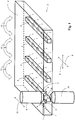
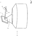
- Fig. 1 shows a detailed view of an embodiment of an optical device according to the invention for microscopic examination of a large number of samples 1 to explain a possible embodiment of the method according to the invention.
- the optical device has a sample holder 2, the samples 1 to be examined being held in several sub-holders 3 of the sample holder 2.
- the sub-holders 3 are each designed as a strand-shaped cuboid.
- Each sub-holder 3 consists of a dimensionally stable embedding medium, for example agarose or a - preferably similar - gel-like, transparent medium in which the samples 1 held by the respective sub-holder 3 are embedded.
- the sub-holders 3 are arranged in a common, preferably horizontal, plane and parallel to one another in a transparent shell 4 of the sample holder 2, which is filled with an immersion liquid (not shown). Due to this special design of the sample holder 2 and the special arrangement of the samples 1 held, a free space for a deflection means 6, which has two deflection mirrors 7 held by a detection objective 8, advantageously remains on both sides of the samples 1.
- the detection objective 8 is immersed in the immersion liquid (not shown) during the microscopic examination of one of the samples.
- the deflection means 6, which is attached to the detection objective 8, is located in the immersion liquid during the microscopic examination.
- the deflection means 6 is used to deflect a light strip 11 emerging from an illumination objective 10 to an illumination position 5 in such a way that the light strip 11 spreads at an angle other than zero degrees, in particular at a right angle, to the optical axis of the illumination objective 10. In this way, a layer of the sample 1 located in the illumination position 5 is illuminated with the light strip focused by the illumination objective 10.
- the detection light emanating from the illuminated layer is converted through the detection objective 8 into a (in Figure 1 not shown) detector passed.
- the detector can, for example, be a sensor for capturing a two-dimensional image, for example a CCD sensor.
- the sample holder 2 and the sample 1 located in the sample illumination position 5 can be displaced relative to one another perpendicular to the plane of the deflected light strip 11 and / or parallel to the optical axis of the illumination objective 10, by a further one to illuminate the other layer of sample 1 and examine it microscopically.
- the illumination objective 10 can be moved in the direction of its optical axis in order to change the illumination layer.
- deflecting means 6 parallel to the plane of the deflected light strip 11 and / or perpendicular to the optical axis of the illumination objective 10 in order to illuminate another layer of the sample 1 with the deflected light strip 11.
- a three-dimensional image of the sample 1 located in the sample illumination position 5 or image data can be obtained that enable a three-dimensional image of the sample 1 located in the sample illumination position 5.
- the sample holder 2, which holds the samples 1, is preferably motorized and / or automatically mounted so that it can be moved relative to the sample illumination position 5 in such a way that at least one of the samples 1 can be successively positioned in the sample illumination position 5.
- the sample holder 2 is preferably arranged movably guided with a displacement device in two mutually perpendicular directions, one of which is preferably the longitudinal direction of the sub-holder 3, which is illustrated in the figure by the double arrows 9.
- the next sample can be brought into the illumination position 5 and examined microscopically by a simple, in particular horizontal, linear movement of the specimen holder 2 relative to the illumination objective 10.
- the double arrow 12 Only for changing from one sub-holder 3 to the next sub-holder 3, which is illustrated by the curved double arrows 13, is also a relative movement of the Detection objective including the deflection in the vertical direction required.
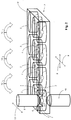
- Fig. 2 shows a detailed view of an optical device not belonging to the invention.
- the sub-holders 3 of the specimen holder 2 just as in the case of the in Fig. 1
- the embodiment shown - arranged in a transparent shell 4.
- the sub-holders 3 of the sample holder are designed as additional, transparent shells filled with a transparent, preferably liquid, embedding medium, in each of which at least one sample 1 is arranged.
- the other shells are arranged in the form of a matrix within the transparent shell 4 in a common plane.
- the detection objective 8 together with the deflection means is introduced into the further shells from above, which is illustrated in the figure by the curved double arrows 13.
- the sample holder is arranged movably guided in two mutually perpendicular directions with a displacement device (not shown), which is illustrated in the figure by the double arrows 9.
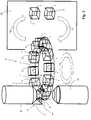
- Fig. 3 shows a detailed view of a further exemplary embodiment of an optical device according to the invention, in which the sample holder 2 has a revolver 14 which carries a large number of samples 1 held in each case in a sub-holder 3.
- the sub-holders 3 are cube-shaped, but there is no restriction to such a shape; rather, other geometric shapes are also possible.
- the sub-holders 3 each consist of a dimensionally stable embedding medium, for example agarose or a - preferably similar - gel-like, transparent medium in which at least one sample 1 is embedded in each case.
- the samples By rotating the turret 14, the samples can be successively brought into the lighting position 5 and examined microscopically.
- FIG. 3 The embodiment shown also has a handling device 14 which automatically arranges the sub-holders 3 with the samples 1 to be examined in the revolver 14 and removes already examined samples 1 together with their sub-holders 3 from the revolver 14.
- the handling device 14 preferably automatically, removes from the turret 14 the samples 1 that have already been examined and have already been removed from the sample illumination position 5 by rotating the turret 14, and further, new samples 1 to be examined together with their sub-holders 3 on the revolver 14, in particular on the ones that have already been examined by removing them Samples 1 vacant positions, handed over.
- a continuous examination process is advantageously achieved, in which samples 1 can be examined successively, endlessly and without interruption.
- the light strip 11 is shown only partially and schematically for the sake of clarity.
- some contour lines of the sub-holder 3 there are not or only partially drawn in in the area of the lighting.
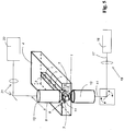
- Fig. 4 shows an embodiment of a possible optical device according to the invention with a sample carrier 2, which is constructed similarly to that in FIG Fig. 1 Sample carriers shown. However, the sample carrier 2 only contains one subcarrier 3.
- the optical device has a light source 16, which is designed as a laser and emits a light beam 17 which is essentially round in cross section.
- the light bundle 17 is formed into a light strip 11 with the aid of cylinder optics 18 and then reaches the illumination objective 10.
- Optical elements 19, such as mirrors and lenses, are provided for guiding and shaping the light bundle 17 and the light strip 11. The process of lighting is carried out as in relation to the in Fig. 1 illustrated embodiment described above.
- the detection light 20 emanating from the sample 1 reaches a detector 22 via further optical elements 21.
- Fig. 5 shows an embodiment of a compared to the embodiment shown in Fig. 4 is shown, modified version.
- the light bundle 17 generated by the light source 16 and having a round cross-section is deflected so quickly in a plane with the aid of a beam deflection device 23, which can include a galvanometer mirror, for example, that a light strip 11 is de facto present in the illumination plane and / or that this illumination with the detectors 22 provided for the detection of the light emanating from the sample 1 and the downstream evaluation devices of a microscope cannot be distinguished from a light strip 11 generated with cylinder optics and / or that the recorded image data do not differ or do not differ significantly from the data which would be generated when illuminated with a continuous light strip 11.
- a beam deflection device 23 can include a galvanometer mirror, for example, that a light strip 11 is de facto present in the illumination plane and / or that this illumination with the detectors 22 provided for the detection of the light emanating from the sample 1 and the downstream evaluation devices of a microscope cannot be
- Fig. 6 shows another embodiment of a possible optical device according to the invention.
- the sample holder 2 consists of a transparent slide plate 24, which has a cuboid sub-holder 3 made of agarose or a similar medium carries.
- the samples 1 to be examined are embedded in the cuboid.
- the sample holder 2 is displaced step by step in the direction of the longitudinal extension direction of the sub-holder 3.
- a special feature is that the sub-holder 3 is produced during the ongoing examination process.
- a sub-holder generating means 25 which has a shaping means 26, is present.
- the sub-holder generating means 25 receives via a first supply line 27 on the one hand agarose or a similar, transparent medium, and on the other hand samples 1 to be embedded via a second supply line 28 the samples 1 supplied through the second feed line 28 are detected.
- the shaping means 26 is arranged in a stationary manner relative to the illumination objective 10 and does not move with the specimen carrier plate 24.
- Fig. 7 shows a schematic representation of a possible course of the light stripe 11.
- the light stripe 11 is generated in that a light bundle 33 is continuously moved back and forth with a beam deflection device (not shown), which is indicated in the figure by the curved double arrow.
- a beam deflection device not shown
- only a brief snapshot is shown in the figure for the sake of clarity.
- the light beam 33 reaches a deflection mirror 7 and is deflected by this in such a way that it is then at an angle different from 0 °, in the present example at a Angle of 90 ° to the optical axis of the illumination lens 10 spreads.
- the light bundle 33 has a focus 32.
- the quasi-light strip 11 generated by the rapid to and fro movement is consequently located in a plane perpendicular to the optical axis of the illumination objective 10.
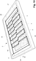
- Fig. 8 an embodiment of a special sample holder is shown.
- Reference numeral 34 shows the direction of movement of the detection objective 8 - which is only indicated schematically - in which there is no collision between the deflecting means 6 or the deflecting mirrors 7 and the sample strip or sub-holder 3.
- a sample strip can be formed from agar-agar, for example, and can contain one to several samples.
- the dotted lines 35 indicate the course of movement of the deflecting mirrors 7, the deflecting mirrors 7 being able to be moved in the free space or the predeterminable area without colliding with the sample strip or sub-holder 3.
- the free space or the predeterminable area depends on the distance between the two deflecting mirrors 7 and on the extent of the sample strip or sub-holder 3.
- the distance between two adjacent sub-holders 3 must be sufficiently large to avoid collisions between the sub-holders 3 and the deflection means 6 or deflection mirrors 7 or other components which are arranged on the detection objective 8.
- the dotted center line 36 shows a possible course of movement in a safe area 37 in which the detection objective 8 can be moved without cutting through a sample strip or sub-holder 3.
- the restricted movement area 38 in which the sample strips or sub-holders 3 may be located, is shown with a gray background.
- a relative movement between the specimen holder 2 and the detection objective 8 may only take place in certain movement paths parallel to the sub-holder 3, namely in such a way that it is always ensured that no specimen or sub-holder 3 can be damaged by the observation objective 8.
- the sample holder 2 has integrated calibration objects or markers 39 which have distinctive points at predetermined positions, fluorescent points, fluorescent patterns (beat clusters) or microstructures visible in the microscopic transmitted light mode.
- Such an integrated marker 39 could in particular also serve for calibration purposes, namely it could be approached in order to be able to determine, for example, a relative position between the illumination and / or detection objective and the sample holder 2.
- Fig. 9 an embodiment of a sample holder 2 with essentially elongated sub-holders 3 in a shell 4 is shown in a perspective view.
- the sub-holders 3 are arranged essentially parallel to one another.
- the course of movement 37 of the in Fig. 9 The detection objective (not shown) has a meander shape or extends in the safe area along the longitudinal side and the transverse side of the specimen holder 2.
- the positions of the sub-holders 3 can be fixed. The positions can be read out from a memory when the system detects that samples are to be detected on the special sample holder 2.
- a further exemplary embodiment of a sample holder 2 with sub-holders 3 in a shell 4 is shown in a perspective view.
- the sub-holders 3 can have different lengths and are arranged essentially parallel to one another.
- the longitudinal directions of the sub-holders 3 can, however, also be oriented along different directions (not shown) or not arranged in parallel.
- Fig. 10 is an optimized, calculated course of movement 37 of the in Fig. 10 detection lens not shown shown shown. This could be the shortest course of movement of the detection objective and / or the shortest detection duration, although a collision between the detection objective / deflection means and the sample should be avoided.
- the shortest course of movement between the end point 40 of one sub-holder 3 and the starting point 41 of the next sub-holder 3 is determined. If the end point 42 is too close to the edge of the restricted movement area 38, the next sub-holder 3 is approached via the safe area 37.
Description
Die Erfindung betrifft ein Verfahren zum mikroskopischen Untersuchen einer Vielzahl von Proben.The invention relates to a method for microscopic examination of a large number of samples.
Die Erfindung betrifft außerdem eine optische Vorrichtung, zum mikroskopischen Untersuchen einer Vielzahl von Proben, mit einem Probenhalter, der eine Vielzahl von Proben hält und der, insbesondere motorisch und/oder automatisch, relativ zu einer Probenbeleuchtungsposition derart bewegbar gelagert ist, dass sukzessive jeweils zumindest eine der Proben in der Probenbeleuchtungsposition positionierbar ist.The invention also relates to an optical device for microscopic examination of a large number of samples, with a sample holder which holds a large number of samples and which, in particular motorized and / or automatically, is movably mounted relative to a sample illumination position in such a way that at least one successively the samples can be positioned in the sample illumination position.
Es besteht bei einigen Anwendungen, beispielsweise für besondere Reihenuntersuchungen oder statistische Untersuchungen, das Bedürfnis, schnell und vorzugsweise automatisch eine Vielzahl von Proben nacheinander mikroskopisch zu untersuchen. Beispielsweise ist aus
Eine solche Lösung ist nicht nur sehr aufwändig, sie hat auch den Nachteil, dass ein dreidimensionales Abbilden einer Vielzahl von Proben nach wie vor sehr lange dauern würde, was insbesondere bei den zumeist lebensdauerbegrenzten, lichtempfindlichen Proben nicht akzeptabel ist.Such a solution is not only very complex, it also has the disadvantage that three-dimensional imaging of a large number of samples would still take a very long time, which is particularly unacceptable in the case of the mostly life-limited, light-sensitive samples.
Viele mikroskopisch zu untersuchende Proben weisen eine begrenzte Lebensdauer auf. Dieser Umstand ist u.a. oft durch ihre Lichtempfindlichkeit begründet. Insoweit ist eine dreidimensionale Abtastung von beispielsweise matrixförmig auf einem Probenträger angeordneten Proben, beispielsweise mit einem Scanmikroskop, in der Praxis problematisch, weil der Scanvorgang viel Zeit in Anspruch nimmt und während des Scanvorganges jeweils auch Probenbereiche mit Beleuchtungslicht beaufschlagt und dadurch geschädigt werden, die außerhalb des gerade relevanten Rasterpunktes liegen.Many samples to be examined microscopically have a limited lifespan. One of the reasons for this is their sensitivity to light. In this respect, three-dimensional scanning of samples, for example arranged in a matrix on a sample carrier, for example with a scanning microscope, is problematic in practice because the scanning process takes a lot of time and, during the scanning process, sample areas are exposed to illuminating light and thereby damaged that are outside the just relevant grid point lie.
Eine ganz andere Technik, bei der eine schichtweise Beleuchtung der Probe erfolgt, erlaubt zwar grundsätzlich eine schnellere und probenschonendere Erfassung von Bilddaten, ist jedoch bislang nicht für schnelle Massenuntersuchungen von Proben geeignet, weil die erforderlichen optischen Vorrichtungen technisch sehr aufwändig sind und weil die Proben einzeln und individuell in besonderen Vorrichtungen angeordnet und die Beobachtungsvorrichtung aufwändig jeweils individuell für jede Probe eingerichtet werden muss. Dieses Verfahren ist insbesondere unter der Bezeichnung SPIM (Single Plane Illumination Microscopy) bekannt.A completely different technique, in which the sample is illuminated in layers, basically allows a faster and more gentle acquisition of image data, but has so far not been suitable for rapid mass examinations of samples because the optical devices required are technically very complex and because the samples individually and individually arranged in special devices and the observation device has to be set up individually for each sample in a complex manner. This method is known in particular under the name SPIM (Single Plane Illumination Microscopy).
Ein nach dem SPIM-Verfahren arbeitendes Mikroskop ist in
Insbesondere kann diese Methode in aller Regel nicht mit Vorrichtungen ausgeführt werden, die einen klassischen Mikroskopaufbau mit einem Standard-Mikroskopstativ aufweisen. Vielmehr sind zur Ausführung dieser Techniken aufwändige und komplizierte Spezialanordnungen nötig.In particular, this method can generally not be carried out with devices that have a classic microscope structure with a standard microscope stand. Rather, expensive and complicated special arrangements are necessary to carry out these techniques.
Aus
Insbesondere zur Untersuchung von aquatischen Organismen ist es auch bekannt, die Proben nicht mit einem Probenhalter zu halten, sondern durch eine Glaskapillare zu saugen, die mit einem Lichtblatt durchleuchtet wird. Eine solche Vorgehensweise ist beispielsweise aus dem Artikel
Ein Mikroskop zur Untersuchung von Proben ist aus der
Es ist daher die Aufgabe der vorliegenden Erfindung, ein Verfahren anzugeben, das es ermöglicht, probenschonend, effizient, präzise und vorzugsweise automatisiert eine mikroskopische Untersuchung einer Vielzahl von Proben vorzunehmen.It is therefore the object of the present invention to provide a method which makes it possible to carry out a microscopic examination of a large number of samples in a manner that is gentle on the sample, efficiently, precisely and preferably in an automated manner.
Die Aufgabe wird durch ein Verfahren nach Anspruch 1 gelöst.The object is achieved by a method according to
Es ist außerdem eine Aufgabe der vorliegenden Erfindung, eine Vorrichtung anzugeben, die es ermöglicht, probenschonend, effizient, präzise und vorzugsweise automatisiert eine mikroskopische Untersuchung einer Vielzahl von Proben vorzunehmen.It is also an object of the present invention to provide a device which enables a microscopic examination of a large number of samples to be carried out in an efficient, precise and preferably automated manner in a manner that is gentle on the sample.
Diese Aufgabe wird durch ein Mikroskop nach Anspruch 15 gelöst.This object is achieved by a microscope according to
Durch die Erfindung ist es ermöglicht, bei hohem Bildkontrast und niedriger Phototoxizität eine Massenuntersuchung von lichtempfindlichen Proben, wie beispielsweise lebenden Zellverbänden, wie zum Beispiel Gewebekulturen von Hautzellen und Embryonalentwicklung von Wirbeltieren, vorzunehmen. Hierbei ist auch ein hoher Durchsatz von Proben pro Zeiteinheit ermöglicht, ohne dass Einbußen hinsichtlich der vorgenannten Parameter hingenommen werden müssen. Insbesondere ermöglicht die vorliegende Erfindung in vorteilhafter Weise eine automatisierte Massenuntersuchung von Proben vornehmen zu können, was insbesondere durch die erfindungsgemäße Ausnutzung der SPIM-Technologie in Verbindung mit der erfindungsgemäßen Anordnung und Verwendung des Probenhalters und der besonderen Strahlführung relativ zu den Proben unterstützt wird.The invention makes it possible, with high image contrast and low phototoxicity, to carry out a mass examination of light-sensitive samples, such as, for example, living cell aggregates, such as, for example, tissue cultures of skin cells and embryonic development of vertebrates. This also enables a high throughput of samples per unit of time without having to accept any losses with regard to the aforementioned parameters. In particular, the present invention advantageously enables an automated mass analysis of samples to be carried out, which is supported in particular by the inventive use of the SPIM technology in connection with the inventive arrangement and use of the sample holder and the special beam guidance relative to the samples.
Beispielsweise können die Proben mit dem Probenhalter in Matrixform und/oder in einer gemeinsamen Ebene gehalten sein. Eine solche Probenanordnung ermöglicht ein schnelles und präzises, sukzessives Wechseln der Proben in die Probenbeleuchtungsposition durch einfache Verschiebebewegungen.For example, the samples with the sample holder can be held in matrix form and / or in a common plane. Such a sample arrangement enables a quick and precise, successive change of the samples in the sample illumination position by simple shifting movements.
Alternativ oder zusätzlich kann auch vorgesehen sein, dass die Proben mit dem Probenhalter in wenigstens einer geraden Reihe gehalten sind. Bei einer solchen Ausführung reicht eine Verschiebebewegung entlang einer einzigen Richtung, die Proben sukzessive in die Probenbeleuchtungsposition zu verbringen.Alternatively or additionally, it can also be provided that the samples are held in at least one straight row with the sample holder. In such an embodiment, a displacement movement along a single direction is sufficient to bring the samples successively into the sample illumination position.
Alternativ können die Proben mit dem Probenhalter in einer gebogenen Reihe, insbesondere in einer ringförmigen Reihe gehalten sein. Insbesondere kann vorgesehen sein, dass der Probenhalter als Revolver ausgebildet ist. Bei diesen Ausführungen können die Proben sukzessive jeweils durch Ausführung einer Drehbewegung in die Probenbeleuchtungsposition verbracht werden.Alternatively, the samples can be held in a curved row, in particular in an annular row, with the sample holder. In particular, it can be provided that the sample holder is designed as a revolver. In these embodiments, the samples can be brought into the sample illumination position successively by executing a rotary movement.
Erfindungsgemäß sind eine oder mehrere der Proben in wenigstens einem Subhalter des Probenhalters gehaltert. Insbesondere kann vorgesehen sein, dass der Probenhalter mehrere, insbesondere strangförmige, Subhalter aufweist. Der Subhalter bzw. die Subhalter kann/können vorteilhaft in einem, insbesondere oben offenen Gefäß, angeordnet sein, das mit einer Immersionsflüssigkeit gefüllt ist; dies insbesondere derart, dass die Proben und/oder der Subhalter, vorzugsweise vollständig, in der Immersionsflüssigkeit untergetaucht sind. Bei der Untersuchung der Proben kann ein Detektionsobjektiv, das insbesondere auch das Umlenkmittel tragen kann, in die Immersionsflüssigkeit eintauchen oder wenigstens mit der Frontlinse in die Immersionsflüssigkeit eingetaucht sein. Vorzugsweise sind während des Untersuchungsvorganges auch das Umlenkmittel, beispielsweise einer oder mehrere Umlenkspiegel, in die Immersionsflüssigkeit eingetaucht.According to the invention, one or more of the samples are held in at least one sub-holder of the sample holder. In particular, it can be provided that the sample holder has several, in particular strand-shaped, sub-holders. The sub-holder or sub-holders can advantageously be arranged in a vessel, in particular an open-top vessel, which is filled with an immersion liquid; this in particular in such a way that the samples and / or the sub-holder are submerged, preferably completely, in the immersion liquid. When examining the samples, a The detection objective, which in particular can also carry the deflecting means, can be immersed in the immersion liquid or at least with the front lens immersed in the immersion liquid. The deflecting means, for example one or more deflecting mirrors, are preferably also immersed in the immersion liquid during the examination process.
Insbesondere kann vorgesehen sein, dass der Probenhalter wenigstens, einen strangförmigen Subhalter aufweist, mit denen jeweils mindestens eine Probe, insbesondere jeweils eine Reihe von Proben, gehaltert ist. Eine solche Ausführung hat den Vorteil, dass sich das Umlenkmittel während des sukzessiven Verbringens der Proben in die Probenbeleuchtungsposition seitlich an dem Subhalter entlang bewegt und/oder sich der strangförmige Subhalter in einer Linearbewegung an dem Umlenkmittel, beispielsweise einem Umlenkspiegel, vorbei bewegt. Insbesondere kann vorteilhaft auch vorgesehen sein, dass der strangförmige Subhalter während des sukzessiven Verbringens der Proben in die Probenbeleuchtungsposition zwischen zwei einander gegenüberliegend angeordneten Umlenkmitteln, beispielsweise Umlenkspiegeln, hindurch bewegt wird.In particular, it can be provided that the sample holder has at least one strand-shaped sub-holder, with which at least one sample, in particular a row of samples, is held in each case. Such an embodiment has the advantage that the deflecting means moves laterally along the sub-holder during the successive bringing of the samples into the sample illumination position and / or the strand-shaped sub-holder moves in a linear movement past the deflecting means, for example a deflecting mirror. In particular, it can advantageously also be provided that the strand-like sub-holder is moved through between two oppositely arranged deflecting means, for example deflecting mirrors, during the successive bringing of the samples into the sample lighting position.
Bei einer besonderen Ausführung weist der Probenhalter mehrere strangförmige Subhalter auf, mit denen jeweils mindestens eine Probe, insbesondere jeweils eine Reihe von Proben, gehaltert ist. Alternativ oder zusätzlich kann vorgesehen sein, dass der Probenhalter mehrere strangförmige Subhalter aufweist, die in einer gemeinsamen Ebene und/oder parallel zueinander ausgerichtet sind und/oder dass der Probenhalter mehrere würfelförmige Subhalter aufweist, mit denen jeweils mindestens eine der Proben gehaltert ist.In a particular embodiment, the sample holder has a plurality of strand-like sub-holders, with which at least one sample, in particular a row of samples, is held in each case. Alternatively or additionally, it can be provided that the sample holder has several strand-shaped sub-holders that are aligned in a common plane and / or parallel to one another and / or that the sample holder has several cube-shaped sub-holders, with which at least one of the samples is held in each case.
Bei einer anderen Ausführung weist der Probenhalter als Schalen ausgebildete Subhalter auf, in denen jeweils mindestens eine Probe angeordnet ist. Es kann auch vorgesehen sein, dass der Probenhalter eine, insbesondere zylinderförmige, Röhre aufweist, in der wenigstens eine der Proben gehalten ist oder in der mehrere der Proben angeordnet, insbesondere aufgereiht, sind. Auch eine solche Ausführung ermöglicht ein schnelles und präzises Verbringen der einzelnen Proben in die Probenbeleuchtungsposition.In another embodiment, the sample holder has sub-holders designed as shells, in each of which at least one sample is arranged. It can also be provided that the sample holder has a, in particular cylindrical, tube in which at least one of the samples is held or in which several of the samples are arranged, in particular in a row. Such a design also enables the individual samples to be moved quickly and precisely into the sample illumination position.
Bei einer besonderen Ausführung ist die Probenbeleuchtungsposition außerhalb des Beleuchtungsobjektivs, jedoch in Verlängerung der optischen Achse des Beleuchtungsobjektivs angeordnet. Auf diese Weise ist es ermöglicht, jeweils mindestens eine Probe präzise, effizient und bauraumsparend beleuchten zu können. Darüber hinaus ermöglicht eine solche Anordnung eine mechanisch besonders robuste Ausführung. Dies insbesondere, weil lange Trägerarme zum halten optischer Bauteile, die in störender Weise in Schwingung geraten können, vermieden sind. Insbesondere hierbei kann vorteilhaft vorgesehen sein, dass das Beleuchtungslicht außermittig durch das Beleuchtungsobjektiv geführt wird.In a special embodiment, the sample illumination position is arranged outside the illumination objective, but in an extension of the optical axis of the illumination objective. In this way, it is possible to illuminate at least one sample precisely, efficiently and in a space-saving manner. In addition, such an arrangement enables a mechanically particularly robust design. This is in particular because long support arms for holding optical components, which can vibrate in a disruptive manner, are avoided. In particular, it can advantageously be provided here that the illuminating light is guided eccentrically through the illuminating lens.
Bei einer besonders vorteilhaften Ausführung weist wenigstens ein Subhalter ein, vorzugsweise durchsichtiges, Einbettungsmedium, insbesondere Agarose oder ein - vorzugsweise ähnliches - gelartiges, durchsichtiges Medium und/oder eine ähnliche, galertartige, durchsichtige Matrix, auf, in das die von dem Subhalter gehaltene Probe eingebettet ist oder die von dem Subhalter gehaltenen Proben eingebettet sind. Eine solche Ausführung hat den besonderen Vorteil, dass die jeweilige Probe ohne Abschattung durch undurchsichtige Haltebauteile beobachtet werden kann. Darüber hinaus kann durch ein Einbettungsmedium eine zum Erhalt der Proben günstige und schützende Umgebung geschaffen werden.In a particularly advantageous embodiment, at least one sub-holder has a preferably transparent, embedding medium, in particular agarose or a - preferably similar - gel-like, transparent medium and / or a similar, jelly-like, transparent matrix in which the sample held by the sub-holder is embedded or the samples held by the sub-holder are embedded. Such a design has the particular advantage that the respective sample can be observed without being shaded by opaque holding components. In addition, an embedding medium can be used to create an environment that is favorable and protective for preserving the samples.
Bei einer besonderen Ausführung ist vorgesehen, dass die Proben, die bereits untersucht wurden und bereits aus der Probenbeleuchtungsposition entfernt wurden, insbesondere automatisch, aus dem Probenhalter entnommen werden. Insbesondere kann zusätzlich vorgesehen sein, dass, insbesondere automatisch, weitere zu untersuchende Proben an den Probenhalter, insbesondere an freigewordene Positionen des Probenhalters, übergeben werden. Auf diese Weise ist vorteilhaft ein kontinuierlicher Untersuchungsprozess möglich, bei dem sukzessive, endlos und unterbrechungsfrei Proben untersucht werden können.In a special embodiment it is provided that the samples that have already been examined and have already been removed from the sample illumination position, in particular automatically, are removed from the sample holder. In particular, it can additionally be provided that, in particular automatically, further samples to be examined are transferred to the sample holder, in particular to positions of the sample holder that have become free. In this way, a continuous examination process is advantageously possible, in which samples can be examined successively, endlessly and without interruption.
Wie bereits erwähnt kann beispielsweise vorgesehen sein, dass der Probenhalter gedreht wird, um jeweils die nächste zu untersuchende Probe in der Beleuchtungsposition zu positionieren. Insbesondere kann vorgesehen sein, dass der Probenhalter um die optische Achse des Beleuchtungsobjektivs oder um eines zur optischen Achse des Beleuchtungsobjektivs parallele Achse gedreht wird, um jeweils die nächste zu untersuchende Probe in der Beleuchtungsposition zu positionieren. Eine solche Vorgehensweise bietet sich vorteilhaft insbesondere dann an, wenn die Proben in dem Probenhalter ringförmig angeordnet sind.As already mentioned, it can be provided, for example, that the sample holder is rotated in order to position the next sample to be examined in the illumination position. In particular, it can be provided that the sample holder is rotated around the optical axis of the illumination objective or around an axis parallel to the optical axis of the illumination objective in order to position the next sample to be examined in the illumination position. Such a procedure is advantageous in particular when the samples are arranged in the form of a ring in the sample holder.
Alternativ oder zusätzlich kann vorgesehen sein, dass der Probenhalter relativ zur Beleuchtungsposition in wenigstens einer Richtung linear verschoben wird, um jeweils die nächste zu untersuchende Probe in der Beleuchtungsposition zu positionieren und/oder dass eine Verschiebevorrichtung vorhanden ist, mit der der Probenhalter, insbesondere automatisch, in zwei verschiedene, insbesondere zueinander orthogonale, Richtungen verschiebbar ist und/oder dass eine Verschiebevorrichtung vorhanden ist, mit der der Probenhalter, insbesondere automatisch, in drei verschiedene, insbesondere zueinander orthogonale, Richtungen verschiebbar ist.Alternatively or additionally, it can be provided that the sample holder is linearly displaced in at least one direction relative to the illumination position in order to position the next specimen to be examined in the illumination position and / or that a displacement device is present with which the specimen holder, in particular automatically, is displaceable in two different, in particular mutually orthogonal, directions and / or that a displacement device is present with which the sample holder can be displaced, in particular automatically, in three different, in particular mutually orthogonal, directions.
Bei einer besonderen Ausführung sind das Umlenkmittel und die in der Beleuchtungsposition befindliche Probe in einer gemeinsamen Ebene angeordnet, wobei das Umlenkmittel innerhalb dieser Ebene die in der Beleuchtungsposition befindliche Probe nur unvollständig, insbesondere nur einseitig oder auf zwei gegenüberliegenden Seiten, umgibt. Vorzugsweise bleibt wenigstens ein Bereich innerhalb der genannten Ebene frei, durch den Proben in die Probenbeleuchtungsposition verbracht und aus dieser entfernt werden können. Eine solche Ausführung hat den besonderen Vorteil, dass die Proben mit dem Proebenhalter in der genannten Ebene bevorratet sein können und dass durch eine oder mehrere Verschiebebewegungen der Proben ausschließlich in der genannten, gemeinsamen Ebene, die insbesondere auch die Beleuchtungsebene sein kann, jeweils eine Probe in die Probebeleuchtungsposition verbracht werden kann oder aus dieser entfernt werden kann, ohne dass eine Positionierungsbewegung senkrecht zu der genannten gemeinsamen Ebene notwendig ist.In a special embodiment, the deflection means and the sample located in the illumination position are arranged in a common plane, the deflection means within this plane only incompletely surrounding the sample located in the illumination position, in particular only on one side or on two opposite sides. At least one area preferably remains free within said plane through which samples can be brought into the sample illumination position and removed from it. Such Execution has the particular advantage that the samples can be stored with the sample holder in the mentioned plane and that one sample in each case is brought into the sample illumination position by one or more displacement movements of the samples exclusively in the mentioned common plane, which can in particular also be the illumination plane can be brought or can be removed from this without a positioning movement perpendicular to the mentioned common plane is necessary.
Bei einer ganz besonders vorteilhaften Ausführung wird der Typ des jeweils verwendeten Probenhalters automatisch, insbesondere softwaregesteuert, erkannt, so dass anschließend das sukzessive Positionieren der Proben in der Probenbeleuchtungsposition, insbesondere automatisch, unter Berücksichtigung des erkannten Typs und/oder unter Verwendung einer dem erkannten Typ zugeordneten, insbesondere in einem Softwarespeicher abgelegten, Positionswechselroutine erfolgen kann. Auf diese Weise ist es möglich, unterschiedliche Typen von Probenhaltern, beispielsweise strangförmige oder revolverförmige Probenhalter, verwenden zu können, wobei sich die optische Vorrichtung, vorzugsweise automatisch, an den gerade aktuellen Typ von Probenhalter anpasst.In a particularly advantageous embodiment, the type of the sample holder used is automatically, in particular software-controlled, recognized, so that the successive positioning of the samples in the sample illumination position, in particular automatically, taking into account the recognized type and / or using one assigned to the recognized type , in particular stored in a software memory, position change routine can take place. In this way, it is possible to use different types of sample holders, for example strand-shaped or revolver-shaped sample holders, the optical device, preferably automatically, adapting to the current type of sample holder.
In vorteilhafter Weise kann vorgesehen sein, dass die zu untersuchenden Proben automatisch, beispielsweise mit einem Bestückungsautomaten, in dem Probenhalter und/oder in einem Subhalter des Probenhalters angeordnet werden. Hierbei kann außerdem vorteilhaft vorgesehen sein, dass die Proben im Hinblick auf die mikroskopische Untersuchung, vorzugsweise automatisch, vorteilhaft innerhalb des Probenhalters ausgerichtet werden.Provision can advantageously be made for the samples to be examined to be arranged automatically, for example with an automatic placement machine, in the sample holder and / or in a sub-holder of the sample holder. It can also be advantageously provided here that the samples are advantageously aligned within the sample holder with regard to the microscopic examination, preferably automatically.
Der Lichtstreifen kann beispielsweise mit einer Zylinderoptik aus einem im Querschnitt runden Lichtbündel, beispielsweise eines Lasers, erzeugt werden. Es ist alternativ auch möglich, dass der Lichtstreifen ein Quasi-Lichtstreifen ist, der aus einem in einer Lichtstreifenebene kontinuierlich hin- und her bewegtem Lichtbündel besteht. Hierzu kann die optische Vorrichtung beispielsweise eine Strahlablenkvorrichtung aufweisen, mit der ein Lichtbündel vorzugsweise derart schnell in einer Beleuchtungsebene bewegbar ist, dass de facto in der Beleuchtungsebene ein Lichtstreifen vorliegt und/oder dass diese Beleuchtung mit den zur Detektion des von der Probe ausgehenden Lichtes vorgesehenen Detektoren und den nachgeschalteten Auswertevorrichtungen eines Mikroskops nicht von einem kontinuierlichen, beispielsweise mit einer Zylinderoptik erzeugten, Lichtstreifen unterscheidbar ist und/oder dass die aufgenommenen Bilddaten sich nicht oder nicht wesentlich von den Daten unterscheiden, die bei einer Beleuchtung mit einem kontinuierlichen Lichtstreifen erzeugt würden.The light strip can be generated, for example, with cylinder optics from a light bundle with a round cross-section, for example a laser. As an alternative, it is also possible for the light strip to be a quasi-light strip which consists of a light beam that is continuously moved back and forth in a light strip plane. For this purpose, the optical device can have, for example, a beam deflection device with which a light bundle can preferably be moved so quickly in an illumination plane that there is de facto a light strip in the illumination plane and / or that this illumination is carried out with the detectors provided for detecting the light emanating from the sample and the downstream evaluation devices of a microscope cannot be distinguished from a continuous strip of light, for example generated with cylinder optics, and / or that the recorded image data do not differ, or do not differ significantly, from the data that would be generated when illuminated with a continuous strip of light.
Vorzugsweise ist die Lichtstreifenebene, in der sich der umgelenkte Lichtstreifen ausbreitet, senkrecht zur optischen Achse des Beleuchtungsobjektivs und/oder des Detektionsobjektivs ausgerichtet.The light stripe plane in which the deflected light stripe spreads is preferably perpendicular to the optical axis of the illumination objective and / or the Detection objective aligned.
Bei einer besonderen Ausführung ist vorgesehen, dass das von der Probe ausgehende Detektionslicht ebenfalls durch das Beleuchtungsobjektiv verläuft und/oder mit dem Beleuchtungsobjektiv kollimiert wird.In a particular embodiment, it is provided that the detection light emanating from the sample likewise runs through the illumination objective and / or is collimated with the illumination objective.
Alternativ ist es jedoch auch möglich, dass das von der Probe ausgehende Detektionslicht durch ein Detektionsobjektiv verläuft und/oder mit einem Detektionsobjektiv kollimiert wird. Hierbei kann insbesondere vorgesehen sein, dass die optische Achse des Beleuchtungsobjektivs und die optische Achse des Detektionsobjektivs parallel und/oder kollinear zueinander ausgerichtet sind. Eine solche Ausführung hat den besonderen Vorteil, dass die optische Vorrichtung besonders kompakt und robust ausgeführt werden kann und dass der Probenbeleuchtungsbereich besonders einfach zugänglich ist, so dass ein schnelles und präzises, sukzessives Verbringen der Proben in den Probenbeleuchtungsbereich ermöglicht ist.Alternatively, however, it is also possible for the detection light emanating from the sample to run through a detection objective and / or to be collimated with a detection objective. In this case, it can be provided in particular that the optical axis of the illumination objective and the optical axis of the detection objective are aligned parallel and / or collinear to one another. Such a design has the particular advantage that the optical device can be designed to be particularly compact and robust and that the sample illumination area is particularly easy to access, so that the samples can be moved quickly and precisely, successively, into the sample illumination area.
Insbesondere kann vorteilhaft vorgesehen sein, dass der Lichtstreifen zunächst in vertikaler Richtung durch das Beleuchtungsobjektiv verläuft und anschließend in horizontale Richtung mit dem Umlenkmittel umgelenkt wird, um eine Schicht der Probe zu beleuchten. Vorzugsweise verläuft das von der beleuchteten Schicht ausgehende Licht, insbesondere Fluoreszenzlicht, in vertikaler Richtung durch ein Detektionsobjektiv. Ein solcher Aufbau ermöglicht die Verwendung von aufrechten oder inversen Standard-Mikroskopstativen zur Herstellung der erfindungsgemäßen optischen Vorrichtung.In particular, it can advantageously be provided that the light strip initially runs in the vertical direction through the illumination objective and is then deflected in the horizontal direction with the deflection means in order to illuminate a layer of the sample. The light emanating from the illuminated layer, in particular fluorescent light, preferably runs in the vertical direction through a detection objective. Such a structure enables the use of upright or inverted standard microscope stands for the production of the optical device according to the invention.
Die Umlenkvorrichtung, die beispielsweise einen oder mehrere Umlenkspiegel aufweisen kann, kann vorteilhaft an dem Beleuchtungsobjektiv und/oder an dem Detektionsobjektiv, insbesondere beweglich, befestigt sein. Bei der Verwendung eines inversen Mikroskopstativs zur Herstellung der erfindungsgemäßen optischen Vorrichtung ist eine besonders robuste und kompakte Ausführung dadurch ermöglicht, dass das Umlenkmittel an dem Detektionsobjektiv, das anstelle eines Kondensors an der Kondensorposition des inversen Mikroskopstativs angeordnet ist, gehalten ist.The deflecting device, which can have one or more deflecting mirrors, for example, can advantageously be attached to the illumination objective and / or to the detection objective, in particular movably. When using an inverted microscope stand to manufacture the optical device according to the invention, a particularly robust and compact design is made possible in that the deflecting means is held on the detection objective, which is arranged instead of a condenser at the condenser position of the inverted microscope stand.
Im Hinblick auf eine zuverlässige Einstellbarkeit der Einstrahlrichtung und/oder des Einstrahlortes auf die jeweils in der Probenbeleuchtungsposition befindliche Probe, kann vorteilhaft vorgesehen sein, dass das Beleuchtungsobjektiv und die Umlenkvorrichtung relativ zueinander beweglich angeordnet sind und/oder dass die Umlenkvorrichtung beweglich an dem Beleuchtungsobjektiv befestigt ist und/oder dass die Umlenkvorrichtung beweglich an dem Detektionsobjektiv befestigt ist. Eine solche Ausführung erlaubt in vorteilhafter Weise darüber hinaus, ein Beleuchtungsobjektiv mit hoher numerischer Apertur auch dann verwenden zu können, wenn eine zu untersuchende Probe größer als das Bildfeld des Beleuchtungsobjektivs ist. Die Verwendbarkeit hochaperturiger Beleuchtungsobjektive hat den besonderen Vorteil, dass der Lichtstreifen oder der Quasi-Lichtstreifen, der die Probe trifft, besonders dünn ausgeformt sein kann, was das Auflösungsvermögen erhöht.With regard to a reliable adjustability of the irradiation direction and / or the irradiation location on the respective sample located in the sample illumination position, it can advantageously be provided that the illumination objective and the deflection device are arranged movably relative to one another and / or that the deflection device is movably attached to the illumination objective and / or that the deflection device is movably attached to the detection objective. Such a design also advantageously allows an illumination objective with a high numerical aperture to be used even when a sample to be examined is larger than the image field of the illumination objective. The use of high-aperture lighting lenses has the particular advantage that the light strip or the quasi-light strip, that hits the sample can be made particularly thin, which increases the resolving power.
Im Folgenden wird darauf eingegangen, dass ein Verfahren des Detektionsobjektives vorzugsweise nur innerhalb vorgegebener Bereiche erfolgt.In the following it will be discussed that a movement of the detection objective preferably only takes place within predetermined ranges.
Durch die seitliche Anordnung der Umlenkmittel jeweils rechts und links ist das Verfahren der Probe bzw. des Probenhalters im Verhältnis zum Detektionsobjektiv eingeschränkt. Um eventuelle Kollisionen mit der Probe zu vermeiden wird eine Absicherung benötigt, die das Positionieren/Verfahren des Probentisches bzw. Probenhalters relativ zum Detektionsobjektiv nur innerhalb vorgegebener Bereiche erlaubt. Diese vorgegebenen Bereiche können sowohl über die Steuerungssoftware als auch über mechanische und elektronische Schalter definiert sein.Due to the lateral arrangement of the deflection means on the right and left, the movement of the sample or the sample holder in relation to the detection objective is restricted. In order to avoid possible collisions with the sample, a safeguard is required that allows the sample table or sample holder to be positioned / moved relative to the detection objective only within predetermined areas. These predefined areas can be defined both via the control software and via mechanical and electronic switches.
Zur Sicherstellung, dass das Umlenkmittel nicht mit der Probe kollidiert, muss ein genügend großer Freiraum zwischen Probe und Umlenkmittel vorhanden sein.To ensure that the deflection means does not collide with the sample, there must be a sufficiently large free space between the sample and the deflection means.
Dieser Freiraum kann auch benutzt werden, um die interessante Stelle innerhalb der Probe in die Mitte des Lichtstreifens zu positionieren.This free space can also be used to position the point of interest within the sample in the center of the light strip.
Besonders hinsichtlich der - vorzugsweise softwarebedingten - Definition der Verfahreinschränkung können die vorgegebenen Bereiche festgelegt werden,
- a) indem die Anordnung multipler Proben oder Subhalter in einer speziellen Probenkammer bzw. auf einem speziellen Probenhalter genau vorgegeben wird bzw. ist, welche in der Steuerungssoftware gespeichert ist. Diese können nach Bedarf geladen werden, z.B. automatisch durch die Erkennung / das Auslesen beim Einsetzen spezieller Probenhalter oder manuell. Ein Ausführungsbeispiel eines speziellen Probenhalters ist in
Fig. 8 gezeigt; - b) und/oder indem die in dem Probenhalter enthaltenen Proben bzw. Subhalter durch ein Bildgebungsverfahren voruntersucht werden und über eine automatisierte Bildanalyse des aufgenommenen Bilds die Positionen bzw. die Anordnung der Proben / Subhalter berechnet werden. Hierfür können unterschiedliche mikroskopische Verfahren verwendet werden, z.B. Konfokal-, Durchlicht-, Phasenkontrast-, Multiphoton-, Reflexions- und Epifluoreszenzmikroskopie. Durch die Anwendung einzelner Verfahren oder durch die Kombination mehrerer Methoden können so die Bereiche bestimmt werden, in denen sich der Probentisch bewegen kann, ohne dass das Umlenkmittel mit der Probe kollidiert. Außerdem können speziell für diesen Zweck hergestellte Probenkammern und Einbettmedien dabei helfen, zum Beispiel durch die Anwendung fluoreszierender Marker, den Probenraum genauer zu charakterisieren.
- a) in that the arrangement of multiple samples or sub-holders in a special sample chamber or on a special sample holder is or is precisely specified, which is stored in the control software. These can be loaded as required, e.g. automatically through the recognition / readout when inserting special specimen holders or manually. An embodiment of a special sample holder is shown in FIG
Fig. 8 shown; - b) and / or in that the samples or sub-holders contained in the sample holder are pre-examined by an imaging method and the positions or the arrangement of the samples / sub-holders are calculated using an automated image analysis of the recorded image. Different microscopic methods can be used for this, eg confocal, transmitted light, phase contrast, multiphoton, reflection and epifluorescence microscopy. By using individual methods or by combining several methods, the areas in which the sample table can move can be determined without the deflecting means colliding with the sample. In addition, sample chambers and embedding media specially produced for this purpose can help to characterize the sample space more precisely, for example by using fluorescent markers.
Zur Detektion des Freiraums bzw. des vorgebbaren Bereichs, in welchem eine Relativbewegung zwischen Umlenkmittel und Probenhalter ohne Kollision zwischen Umlenkmittel und Probe möglich ist, können unterschiedliche optische Methoden eingesetzt werden. Zum einen ist es denkbar, mit einer konfokalen Reflexionsmessung mit Beleuchtungslicht über das Beleuchtungsobjektiv den Übergang vom Deckglas bzw. transparenten Boden des Probenhalters in den Probenbereich zu ermitteln. Liegt eine Probe auf dem Deckglas auf, vermindert sich die Reflexion am Übergang, da typischerweise der Brechungsindex der Probe höher ist als der vom wässrigen Medium. Je höher der Brechungsindexunterschied zwischen Deckglas und Medium/Probe ist, umso höher ist auch die Reflexion am Übergang. Damit lässt sich bestimmen, wo die Probe aufliegt und somit der Freiraum zwischen benachbarten Probenbereichen.Different optical methods can be used to detect the free space or the predeterminable area in which a relative movement between the deflection means and the sample holder is possible without a collision between the deflection means and the sample. On the one hand, it is conceivable to determine the transition from the cover glass or transparent bottom of the sample holder into the sample area using a confocal reflection measurement with illuminating light via the illuminating objective. If a sample lies on the cover slip, the reflection at the transition is reduced, since the refractive index of the sample is typically higher than that of the aqueous medium. The higher the refractive index difference between the cover glass and the medium / sample, the higher the reflection at the transition. This makes it possible to determine where the sample rests and thus the space between adjacent sample areas.
Eine weitere Möglichkeit, um den Freiraum zu bestimmen, sind Verfahren, die die Absorption der Probe ausnutzen. Sowohl mit lichtmikroskopischen Weitfieldverfahren als auch mit scannenden lichtmikroskopischen Verfahren können Bilder aufgenommen werden, die die Umrisse der Probe darstellen und somit den Freiraum zwischen den verschiedenen Proben.Another way of determining the free space is with methods that utilize the absorption of the sample. Both with light microscopic wide-field methods and with scanning light microscopic methods, images can be recorded that show the outlines of the sample and thus the space between the various samples.
Besteht nur ein geringes Absorptionsverhalten der Probe können weitere kontrastverstärkende Verfahren, wie z.B. Differentialinterferenzkontrast (DIC) oder Phasenkontrast, benutzt werden, um die Umrisse besser darzustellen.If there is only a low absorption behavior of the sample, further contrast-enhancing methods, such as differential interference contrast (DIC) or phase contrast, can be used to better represent the outlines.
Denkbar ist auch ein Probenauflagemedium (z.B. Agar, Hydrogel) zumindest teilweise mit einem Farbstoff zu versetzen, so dass diese Auflage oder das Einbettmedium detektiert werden kann. Dieser Farbstoff kann sowohl absorbieren als auch fluoreszieren. Sowohl mit Weitfieldmikroskopie oder Konfokal-/Multiphotonenmikroskopie kann dieser Farbstoff und damit der Probenbereich bestimmt werden.It is also conceivable to add a dye to a sample support medium (e.g. agar, hydrogel) at least partially so that this support or the embedding medium can be detected. This dye can both absorb and fluoresce. This dye and thus the sample area can be determined with wide-field microscopy or confocal / multiphoton microscopy.
Ganz allgemein und insbesondere auch unabhängig von der vorliegenden Erfindung könnte ein Probenhalter wie folgt ausgebildet sein:
Der Probenhalter umfasst einen ausreichend bemessenen sicheren Bereich (Sicherheitsrand), welcher derart bemessen ist, dass ein Detektionsobjektiv mit Umlenkmitteln rund um einen eingeschränkten Bewegungsbereich bewegbar ist. In diesem Sicherheitsrand befinden sich keine "Störungen" in Form von Proben und/oder Subhalter(n), welche eine Kollision mit dem Detektionsobjektiv bzw. den Umlenkmitteln verursachen können. Weiterhin könnte der Probenhalter einen eingeschränkten Bewegungsbereich aufweisen, in welchem einzelne Proben oder Subhalter angeordnet sein können. Vorzugsweise weisen diese beliebig angeordneten Proben bzw. Subhalter jeweils einen vorgebbaren bzw. notwendigen Abstand zu den benachbarten Proben bzw. Subhaltern auf, um ein Abrastern bzw. Abbilden der Proben zu ermöglichen, ohne eine Probe durch das Detektionsobjektiv bzw. Umlenkmittel zu zerstören.In general, and in particular also independently of the present invention, a sample holder could be designed as follows:
The sample holder comprises a sufficiently dimensioned safe area (safety edge), which is dimensioned in such a way that a detection objective with deflection means can be moved around a restricted movement area. In this safety edge there are no "disturbances" in the form of samples and / or sub-holder (s) which could cause a collision with the detection objective or the deflection means. Furthermore, the sample holder could have a restricted range of motion in which individual samples or sub-holders can be arranged. These randomly arranged samples or sub-holders each have a predeterminable or necessary distance from the adjacent samples or sub-holders in order to enable scanning or imaging of the samples without a sample being passed through the To destroy the detection lens or deflection means.
Ein Abrastern der Proben oder Subhalter entlang nur einer Richtung ist insbesondere dann möglich, wenn die Proben bzw. Subhalter im Wesentlichen parallel und in einem geeigneten Abstand angeordnet sind. Der geeignete Abstand hängt von der Dimensionierung des Umlenkmittels ab.Scanning the samples or sub-holders in only one direction is possible in particular if the samples or sub-holders are arranged essentially parallel and at a suitable distance. The suitable distance depends on the dimensioning of the deflection means.
Bevorzugt weist der Probenhalter Markierungen auf, welche insbesondere im eingeschränkten Bewegungsbereich angeordnet sein können. Das korrekte Platzieren von Proben auf dem Probenbehälter kann hierdurch für einen Bediener erleichtert werden, so dass die erforderlichen Abstände zwischen benachbarten Subhaltern bzw. Probenstreifen eingehalten werden können.The specimen holder preferably has markings which can be arranged in particular in the restricted area of movement. The correct placing of samples on the sample container can hereby be made easier for an operator, so that the required distances between adjacent sub-holders or sample strips can be maintained.
In der Zeichnung ist der Erfindungsgegenstand schematisch dargestellt und wird anhand der Figuren nachfolgend beschrieben, wobei gleich wirkende Elemente mit denselben Bezugszeichen versehen sind. Dabei zeigen:
- Fig. 1
- eine Detailansicht eines Ausführungsbeispiels einer erfindungsgemäßen optischen Vorrichtung zur Erläuterung einer möglichen Ausführung des erfindungsgemäßen Verfahrens,
- Fig. 2
- eine Detailansicht eines nicht zur Erfindung gehörenden Beispiels einer optischen Vorrichtung zur Erläuterung einer anderen, möglichen Ausführung eines nicht zur Erfindung gehörenden Verfahrens,
- Fig. 3
- eine Detailansicht eines weiteren Ausführungsbeispiels einer erfindungsgemäßen optischen Vorrichtung zur Erläuterung einer weiteren, möglichen Ausführung des erfindungsgemäßen Verfahrens,
- Fig. 4
- ein Ausführungsbeispiel einer möglichen, erfindungsgemäßen optischen Vorrichtung,
- Fig. 5
- ein Ausführungsbeispiel einer abgewandelten erfindungsgemäßen optischen Vorrichtung,
- Fig. 6
- ein anderes Ausführungsbeispiel einer möglichen, erfindungsgemäßen optischen Vorrichtung,
- Fig. 7
- eine schematische Darstellung eines möglichen Verlaufs des Lichtstreifens,
- Fig. 8
- in einer Aufsicht Ausführungsbeispiel eines speziellen Probenhalters,
- Fig. 9
- in einer perspektivischen Ansicht ein Ausführungsbeispiel eines Probenhalters mit Subhaltern und
- Fig. 10
- in einer perspektivischen Ansicht ein weiteres Ausführungsbeispiel eines Probenhalters mit Subhaltern.
- Fig. 1
- a detailed view of an embodiment of an optical device according to the invention to explain a possible implementation of the method according to the invention,
- Fig. 2
- a detailed view of an example of an optical device not belonging to the invention to explain another possible embodiment of a method not belonging to the invention,
- Fig. 3
- a detailed view of a further embodiment of an optical device according to the invention to explain a further possible embodiment of the method according to the invention,
- Fig. 4
- an embodiment of a possible optical device according to the invention,
- Fig. 5
- an embodiment of a modified optical device according to the invention,
- Fig. 6
- another embodiment of a possible optical device according to the invention,
- Fig. 7
- a schematic representation of a possible course of the light streak,
- Fig. 8
- a top view of an embodiment of a special sample holder,
- Fig. 9
- in a perspective view an embodiment of a sample holder with subholders and
- Fig. 10
- in a perspective view another embodiment of a sample holder with sub-holders.
Die Optische Vorrichtung weist einen Probenhalter 2 auf, wobei die zu untersuchenden Proben 1 in mehreren Subhaltern 3 des Probenhalters 2 gehaltert sind. Die Subhalter 3 sind jeweils als strangförmiger Quader ausgebildet. Jeder Subhalter 3 besteht aus einem formstabilen Einbettungsmedium, beispielsweise aus Agarose oder aus einem - vorzugsweise ähnlichen - gelartigen, durchsichtigen Medium, in das die von dem jeweiligen Subhalter 3 gehaltenen Proben 1 eingebettet sind. Die Subhalter 3 sind in einer gemeinsamen, vorzugsweise horizontalen, Ebene und parallel zueinander in einer durchsichtigen Schale 4 des Probenhalters 2 angeordnet, die mit einer Immersionsflüssigkeit (nicht dargestellt) gefüllt ist. Durch diese spezielle Ausbildung des Probenhalters 2 und die spezielle Anordnung der gehaltenen Proben 1 verbleibt in vorteilhafter Weise beidseitig der Proben 1 jeweils ein Freiraum für ein Umlenkmittel 6, das zwei von einem Detektionsobjektiv 8 gehaltene Umlenkspiegel 7 aufweist.The optical device has a
Das Detektionsobjektiv 8 ist während der mikroskopischen Untersuchung einer der Proben in die (nicht dargestellte) Immersionsflüssigkeit eingetaucht. Das Umlenkmittel 6, das an dem Detektionsobjektiv 8 angebracht ist, befindet sich während der mikroskopischen Untersuchung in der Immersionsflüssigkeit.The
Das Umlenkmittel 6 dient dazu, einen aus einem Beleuchtungsobjektiv 10 ausgetretenen Lichtstreifen 11 zu einer Beleuchtungsposition 5 so umzulenken, dass sich der Lichtstreifen 11 unter einem von Null Grad verschiedenen Winkel, insbesondere unter einem rechten Winkel, zur optischen Achse des Beleuchtungsobjektivs 10 ausbreitet. Auf diese Weise wird eine Schicht der in der Beleuchtungsposition 5 befindlichen Probe 1 mit dem vom Beleuchtungsobjektiv 10 fokussierten Lichtstreifen beleuchtet.The deflection means 6 is used to deflect a
In der
Das von der beleuchteten Schicht ausgehende Detektionslicht, insbesondere Fluoreszenzlicht, wird durch das Detektionsobjektiv 8 hindurch zu einem (in
Nachdem die gewünschten Bildinformationen bezüglich der beleuchteten Schicht aufgenommen sind, können der Probenhalter 2 und die jeweils in der Probenbeleuchtungsposition 5 befindliche Probe 1 relativ zueinander senkrecht zur Ebene des umgelenkten Lichtstreifens 11 und/oder parallel zur optischen Achse des Beleuchtungsobjektivs 10 verschoben werden, um eine weitere, andere Schicht der Probe 1 zu beleuchten und mikroskopisch zu untersuchen. Alternativ ist es auch möglich, das Umlenkmittel und/oder das Beleuchtungsobjektiv 10 zu bewegen, um mit dem umgelenkten Lichtstreifen 11 eine andere Schicht der Probe 1 zu beleuchten. Beispielsweise kann das Beleuchtungsobjektiv 10 in Richtung seiner optischen Achse zum Wechseln der Beleuchtungsschicht bewegt werden. Alternativ oder zusätzlich ist es beispielsweise auch möglich, das Umlenkmittel 6 parallel zur Ebene des umgelenkten Lichtstreifens 11 und/oder senkrecht zur optischen Achse des Beleuchtungsobjektivs 10 zu verschieben, um mit dem umgelenkten Lichtstreifen 11 eine andere Schicht der Probe 1 zu beleuchten.After the desired image information relating to the illuminated layer has been recorded, the
Durch sukzessives Abtasten mehrerer Schichten kann so eine dreidimensionale Abbildung der die jeweils in der Probenbeleuchtungsposition 5 befindliche Probe 1 bzw. können Bilddaten gewonnen werden, die eine dreidimensionale Abbildung der jeweils in der Probenbeleuchtungsposition 5 befindliche Probe 1 ermöglichen.By successively scanning several layers, a three-dimensional image of the
Der Probenhalter 2, der die Proben 1 hält, ist vorzugsweise motorisch und/oder automatisch, relativ zu der Probenbeleuchtungsposition 5 derart bewegbar gelagert, dass sukzessive jeweils zumindest eine der Proben 1 in der Probenbeleuchtungsposition 5 positionierbar ist. Vorzugsweise ist der Probenhalter 2 mit einer Verschiebevorrichtung in zwei zueinander senkrechten Richtungen, von denen eine vorzugsweise die Längserstreckungsrichtung der Subhalter 3 ist, geführt bewegbar angeordnet, was in der Figur durch die Doppelpfeile 9 illustriert ist.The
Dadurch, dass seitlich neben - und zwischen den Subhaltern 3 ausreichend Freiraum für das Umlenkmittel 6 verbleibt, kann durch eine einfache, insbesondere horizontale, Linearbewegung des Probenhalters 2 relativ zu dem Beleuchtungsobjektiv 10 jeweils die nächste Probe in die Beleuchtungsposition 5 verbracht und mikroskopisch untersucht werden. Zum Wechseln von einer Probe 1 zur nächsten Probe 1 desselben Subhalters 3 ist in vorteilhafter Weise lediglich und ausschließlich eine einzige Linearbewegung des Probenhalters 2 relativ zu dem Beleuchtungsobjektiv 10 nötig, was durch den Doppelpfeil 12 angedeutet ist. Lediglich zum Wechseln von einem Subhalter 3 zum nächsten Subhalter 3, was durch die gekrümmten Doppelpfeile 13 illustriert ist, ist auch eine Relativbewegung des Detektionsobjektivs samt dem Umlenkmittel in vertikaler Richtung erforderlich.Because there is sufficient free space for the deflection means 6 to the side next to and between the sub-holders 3, the next sample can be brought into the
Zum Positionieren einer Probe 1 in der Beleuchtungsposition 5 wird das Detektionsobjektiv 8 samt dem Umlenkmittel jeweils von oben in die weiteren Schalen eingeführt, was in der Figur durch die gekrümmten Doppelpfeile 13 illustriert ist. Der Probenhalter ist auch bei dieser Ausführung mit einer (nicht dargestellten) Verschiebevorrichtung in zwei zueinander senkrechten Richtungen geführt bewegbar angeordnet, was in der Figur durch die Doppelpfeile 9 illustriert ist.To position a
Durch Drehen des Revolvers 14 können die Proben sukzessive in die Beleuchtungsposition 5 verbracht und mikroskopisch untersucht werden.By rotating the turret 14, the samples can be successively brought into the
Das in
Hierbei kann insbesondere vorteilhaft vorgesehen sein, dass die Handhabungsvorrichtung 14, vorzugsweise automatisch, die Proben 1, die bereits untersucht wurden und bereits aus der Probenbeleuchtungsposition 5 durch Drehen des Revolvers 14 entfernt wurden, von dem Revolver 14 entnimmt und weitere, neue zu untersuchende Proben 1 samt deren Subhaltern 3 an den Revolver 14, insbesondere an die durch Entnehmen der bereits untersuchten Proben 1 freigewordene Positionen, übergibt. Auf diese Weise ist vorteilhaft ein kontinuierlicher Untersuchungsprozess erreicht, bei dem sukzessive, endlos und unterbrechungsfrei Proben 1 untersucht werden können.In this case, it can be provided in particular advantageously that the handling device 14, preferably automatically, removes from the turret 14 the
In der
Die optische Vorrichtung weist eine Lichtquelle 16 auf, die als Laser ausgebildet ist und ein im Querschnitt im Wesentlichen rundes Lichtbündel 17 emittiert. Das Lichtbündel 17 wird mit Hilfe einer Zylinderoptik 18 zu einem Lichtstreifen 11 geformt und gelangt anschließend zu dem Beleuchtungsobjektiv 10. Zur Führung und Formung des Lichtbündels 17 und des Lichtstreifens 11 sind optische Elemente 19, wie beispielsweise Spiegel und Linsen, vorhanden. Der Vorgang des Beleuchtens erfolgt so, wie in Bezug auf die in
Das von der Probe 1 ausgehende Detektionslicht 20 gelangt über weitere optische Elemente 21 zu einem Detektor 22.The detection light 20 emanating from the
Bei diesem Ausführungsbeispiel besteht der Probenhalter 2 aus einer durchsichtigen Objektträgerplatte 24, die einen quaderförmigen Subhalter 3 aus Agarose oder einem ähnlichen Medium trägt. In den Quader sind die zu untersuchenden Proben 1 eingebettet. Um nacheinander die einzelnen zu untersuchenden Proben 1 in die Beleuchtungsposition 5 zu verbringen, wird der Probenhalter 2 schrittweise in Richtung der Längserstreckungsrichtung des Subhalters 3 verschoben.In this embodiment, the
Eine Besonderheit besteht darin, dass der Subhalter 3 während des laufenden Untersuchungsprozesses hergestellt wird. Hierzu ist ein Subhalter-Erzeugungsmittel 25, das ein Formungsmittel 26 aufweist, vorhanden. Das Subhalter-Erzeugungsmittel 25 empfängt über eine erste Zuleitung 27 einerseits Agarose oder ein ähnliches, durchsichtiges Medium, und andererseits über eine zweite Zuleitung 28 einzubettende Proben 1. Es ist außerdem eine Lichtschrankenanordnung 29 mit einer Lichtquelle 30 und einem Lichtempfänger 31 vorgesehen, die die Abfolge der durch die zweite Zuleitung 28 zugeführten Proben 1 detektiert.A special feature is that the
Das Formungsmittel 26 ist relativ zu dem Beleuchtungsobjektiv 10 ortsfest angeordnet und bewegt sich nicht mit der Objektträgerplatte 24 mit.The shaping means 26 is arranged in a stationary manner relative to the
Das kontinuierlich hin- und her bewegte, aus dem Beleuchtungsobjektiv 10 austretende und von dem Beleuchtungsobjektiv 10 fokussierte Lichtbündel 33 gelangt zu einem Umlenkspiegel 7 und wird von diesem derart umgelenkt, dass er sich anschließend unter einem von 0° verschiedenen Winkel, im vorliegenden Beispiel unter einem Winkel von 90°, zur optischen Achse des Beleuchtungsobjektivs 10 ausbreitet. In der Beleuchtungsposition 5 weist das Lichtbündel 33 einen Fokus 32 auf. Der durch das schnelle Hin- und Herbewegen erzeugte Quasi-Lichtstreifen 11 befindet sich folglich in einer zur optischen Achse des Beleuchtungsobjektivs 10 senkrechten Ebene.The continuously moving back and forth, emerging from the
Es ist auch möglich, aber nicht zwingend erforderlich, die jeweils in der Beleuchtungsposition 5 befindliche Probe 1 mit mehreren Lichtstreifen 11, die sich nach dem Umlenken vorzugsweise alle in derselben Beleuchtungsebene ausbreiten, aus verschiedenen Richtungen - simultan oder sequenziell - zu beleuchten. Dieser Fall ist in der Figur der besseren Übersichtlichkeit halber jedoch nicht eingezeichnet.It is also possible, but not absolutely necessary, to illuminate the
In
Mit der gepunktet eingezeichneten Mittellinie 36 ist ein möglicher Bewegungsverlauf in einem sicheren Bereich 37 gezeigt, in welchem das Detektionsobjektiv 8 bewegt werden kann, ohne einen Probenstreifen bzw. Subhalter 3 zu durchschneiden. Der eingeschränkte Bewegungsbereich 38, in welchem sich die Probenstreifen bzw. Subhalter 3 befinden dürfen, ist grau hinterlegt gezeigt. In dem eingeschränkten Bewegungsbereich 38 darf eine Relativbewegung zwischen Probenhalter 2 und dem Detektionsobjektiv 8 nur in bestimmten, zum Subhalter 3 parallelen Bewegungsbahnen erfolgen, und zwar derart, dass immer sichergestellt ist, dass keine Probe bzw. Subhalter 3 durch das Beobachtungsobjektiv 8 beschädigt werden kann. Der Probenhalter 2 weist integrierte Kalibrierobjekte bzw. Marker 39 auf, welche markante Punkte an vorgegebenen Positionen, fluoreszierende Punkte, fluoreszierende Muster (beat cluster) oder im mikroskopischen Durchlichtmodus sichtbare Mikrostrukturen aufweisen. Ein solcher integrierter Marker 39 könnte insbesondere auch zu Kalibrierzwecken dienen, er könnte nämlich angefahren werden, um beispielsweise eine Relativposition zwischen Beleuchtungs- und/oder Detektionsobjektiv und dem Probenhalter 2 bestimmen zu können.The dotted
In
In
Claims (15)
- Method for microscopically examining a large number of samples, characterized by the following steps:a. arranging the samples (1) in a sample holder (2) having at least one strand-shaped subholder, with which at least one row of samples (1) is held, wherein the sample holder (2) is arranged to be movable relative to a sample illumination position (5) by way of a motor and/or automatically in a manner such that, successively, in each case at least one of the samples (1) is positionable in the sample illumination position (5), wherein a free space for a deflection means (6) is left in each case adjacent to the sample (1) that is currently in the sample illumination position (5),b. focusing a light stripe (11) using an illumination objective (10),c. deflecting the light stripe (11), after the latter has passed through the illumination objective (10), using the deflection means (6) in a manner such that the light stripe (11) propagates at an angle of more than 10 degrees or at a right angle with respect to the optical axis of the illumination objective (10) and has a focus in the sample illumination position (5),d. successively positioning the samples (1), held using the sample holder (2), in the sample illumination position (5) and detecting the detection light emerging from the sample (1) that is respectively located in the sample illumination position (5), whereine. the sample holder (2), in which the samples (1) are held in at least one straight row, is displaced in a step-wise manner in the direction of the longitudinal extent of the subholder (3) in order to bring the individual samples (1) to be examined into the sample illumination position (5) one after the other, orf. the sample holder is rotated in order to position in each case the sample that is to be examined next in the illumination position, wherein the samples (1) are held using the sample holder (2) in a curved or in an annular row.
- Method according to Claim 1, characterized in thata. the sample holder (2) has a plurality of subholders (3) with which in each case at least one sample (1) is held, and/or in thatb. the sample holder (2) has a plurality of strand-shaped subholders (3) that are aligned in a common plane and/or parallel to one another, and/or in thatc. the sample holder (2) has a plurality of cuboid subholders (3) with which in each case at least one of the samples (1) is held, and/or in thatd. the sample holder (2) has subholders (3), which are formed like shells and in which in each case at least one sample (1) is arranged, and/or in thate. the sample holder (2) has a tube in which at least one of the samples (1) is held or in which a plurality of the samples (1) are arranged or situated in one row, and/or in thatf. the sample illumination position (5) is arranged outside the illumination objective (10) but in extension of the optical axis of the illumination objective (10).
- Method according to Claim 2a to 2f, characterized in that at least one subholder (3) has an embedding medium or agarose or a gel-like, transparent medium in which the sample (1), which is held by the subholder (3) is embedded or in which the samples (1), which are held by the subholder (3) are embedded.
- Method according to one of Claims 1 to 3, characterized in thata. the samples (1) that have already been examined and already removed from the sample illumination position (5) are taken out of the sample holder (2), or in thatb. the samples (1) that have already been examined and already removed from the sample illumination position (5) are taken out of the sample holder (2) and further samples (1) to be examined are transferred to the sample holder (2) or to positions of the sample holder (2) that have become free.
- Method according to one of Claims 1 to 4, characterized in thata. the sample holder (2) is rotated in order to position in each case the sample (1) that is to be examined next in the illumination position (5), and/or in thatb. the sample holder (2) is rotated about the optical axis of the illumination objective (10) or about an axis that is parallel to the optical axis of the illumination objective (10) in order to position in each case the sample (1) that is to be examined next in the illumination position (5), and/or in thatc. the sample holder (2) is displaced linearly relative to the illumination position (5) in at least one direction in order to position in each case the sample (1) that is to be examined next in the illumination position (5), and/or in thatd. a displacement apparatus is present, with which the sample holder (2) is displaceable in two different directions or in two directions that are orthogonal to each other, and/or in thate. a displacement apparatus is present, with which the sample holder (2) is displaceable in three different directions or in three directions that are orthogonal to one another.
- Method according to one of Claims 1 to 5, characterized in thata. the deflection means (6) and the sample (1) located in the illumination position (5) are arranged in a common plane, wherein the deflection means (6) within this plane surrounds the sample (1) located in the illumination position (5) merely partially or merely on one side or on two opposite sides, and/or in thatb. at least one region within a plane in which the sample illumination position (5) and the deflection means (6) are located remains free, and through which region the samples (1) can be brought into the sample illumination position (5) and removed therefrom.
- Method according to one of Claims 1 to 6, characterized in that the type of the respectively used sample holder (2) is identified automatically and/or in a manner controlled by software and in that the successive positioning of the samples (1) in the illumination position (5) takes place with consideration of the identified type and/or using a position change routine that is associated with the identified type or is stored in a software memory.
- Method according to one of Claims 1 to 7, characterized in that the samples (1) to be examined are arranged automatically in the sample holder (2) and/or in a subholder (3) of the sample holder (2).
- Method according to one of Claims 1 to 8, characterized in that the light stripe (11) is a quasi-light stripe consisting of a light beam that is continuously moved back and forth in a light stripe plane.
- Method according to one of Claims 1 to 9, characterized in that the light stripe (11) is coupled into the illumination objective (10) in a manner such that it extends eccentrically through the illumination objective (10).
- Method according to one of Claims 1 to 10, characterized in that the detection light emerging from the sample (1) likewise passes through the illumination objective (10) and/or is collimated using the illumination objective (10).
- Method according to one of Claims 1 to 11, characterized in that the detection light emerging from the sample (1) passes through a detection objective (8) and/or is collimated using a detection objective (8).
- Method according to Claim 12, characterized in that the optical axis of the illumination objective (10) and the optical axis of the detection objective (8) are aligned such that they are parallel and/or collinear to one another.
- Method according to one of Claims 1 to 13, characterized in thata. the illumination objective (10) and the deflection apparatus (6) are arranged to be movable relative to one another, and/or in thatb. the deflection apparatus (6) is movably attached to the illumination objective (10), and/or in thatc. the deflection apparatus (6) is movably attached to the detection objective (8).
- Microscope, which is configured for generating a light stripe (11), having an illumination objective (10) for focusing a light stripe (11) and having a deflection means (6) for deflecting the light stripe (11) passing through the illumination objective at an angle that differs from 0 degrees or at an angle of greater than 10 degrees or at a right angle with respect to the optical axis of the illumination objective (10), and having a sample holder (2) having at least one strand-shaped subholder (3), with which at least one row of samples (1) is able to be held in at least one straight, curved or annular row, wherein the sample holder (2) is arranged to be movable relative to a sample illumination position (5) by a motor and/or automatically in a manner such that, successively, in each case at least one of the samples (1) is positionable in the sample illumination position (5), wherein in each case a free space for the deflection means (6) is left in each case adjacent to the sample (1) that is currently in the sample illumination position (5), wherein the optical apparatus is embodied to perform a method according to one of Claims 1 to 14.
Applications Claiming Priority (2)
| Application Number | Priority Date | Filing Date | Title |
|---|---|---|---|
| DE102013211426.5A DE102013211426A1 (en) | 2013-06-18 | 2013-06-18 | Method and optical device for microscopically examining a plurality of samples |
| PCT/EP2014/062907 WO2014202704A1 (en) | 2013-06-18 | 2014-06-18 | Method and optical device for microscopically examining a multiplicity of specimens |
Publications (2)
| Publication Number | Publication Date |
|---|---|
| EP3011379A1 EP3011379A1 (en) | 2016-04-27 |
| EP3011379B1 true EP3011379B1 (en) | 2021-08-18 |
Family
ID=51022841
Family Applications (1)
| Application Number | Title | Priority Date | Filing Date |
|---|---|---|---|
| EP14733586.3A Active EP3011379B1 (en) | 2013-06-18 | 2014-06-18 | Method and optical device for microscopically examining a multiplicity of specimens |
Country Status (5)
| Country | Link |
|---|---|
| US (1) | US10458899B2 (en) |
| EP (1) | EP3011379B1 (en) |
| JP (1) | JP6632523B2 (en) |
| DE (1) | DE102013211426A1 (en) |
| WO (1) | WO2014202704A1 (en) |
Families Citing this family (17)
| Publication number | Priority date | Publication date | Assignee | Title |
|---|---|---|---|---|
| DE102013213781A1 (en) * | 2013-03-20 | 2014-09-25 | Leica Microsystems Cms Gmbh | Method and optical arrangement for manipulating and imaging a microscopic sample |
| DE102013226277A1 (en) * | 2013-12-17 | 2015-06-18 | Leica Microsystems Cms Gmbh | Method and device for examining a sample by means of optical projection tomography |
| LU92505B1 (en) | 2014-07-22 | 2016-01-25 | Leica Microsystems | METHOD AND DEVICE FOR MICROSCOPICALLY EXAMINING A SAMPLE |
| US11085901B2 (en) * | 2014-08-19 | 2021-08-10 | Dan Slater | Acoustical microscope |
| DE102015114756B4 (en) * | 2014-09-25 | 2021-07-22 | Leica Microsystems Cms Gmbh | Mirror device |
| LU93022B1 (en) * | 2016-04-08 | 2017-11-08 | Leica Microsystems | Method and microscope for examining a sample |
| US10310248B2 (en) * | 2016-08-18 | 2019-06-04 | Olympus Corporation | Microscope including a medium container containing an immersion medium in which a specimen container containing an immersion medium and a sample is immersed |
| US10690898B2 (en) * | 2016-09-15 | 2020-06-23 | Molecular Devices (Austria) GmbH | Light-field microscope with selective-plane illumination |
| JP2018096703A (en) * | 2016-12-08 | 2018-06-21 | オリンパス株式会社 | Microplate and microscopic system |
| LU100024B1 (en) * | 2017-01-20 | 2018-07-30 | Leica Microsystems | A method for sequentially examining a plurality of samples, sample carrier unit, and light sheet microscopic imaging unit |
| EP3495865A1 (en) * | 2017-12-07 | 2019-06-12 | European Molecular Biology Laboratory | A sample holder for imaging a plurality of samples |
| JP7329113B2 (en) * | 2018-04-09 | 2023-08-17 | 浜松ホトニクス株式会社 | Sample observation device |
| JP7207860B2 (en) | 2018-04-09 | 2023-01-18 | 浜松ホトニクス株式会社 | Sample observation device |
| DE102018128264B4 (en) * | 2018-11-12 | 2020-08-20 | Leica Microsystems Cms Gmbh | Light sheet microscope |
| DE102018222271A1 (en) * | 2018-12-19 | 2020-06-25 | Carl Zeiss Microscopy Gmbh | Method for operating a sample chamber for microscopic imaging and device and sample chamber |
| JP7108564B2 (en) * | 2019-03-06 | 2022-07-28 | アンリツ株式会社 | X-ray inspection device |
| EP4341664A1 (en) * | 2021-05-19 | 2024-03-27 | Leica Microsystems CMS GmbH | Method and apparatus for imaging a biological sample |
Family Cites Families (12)
| Publication number | Priority date | Publication date | Assignee | Title |
|---|---|---|---|---|
| US5002377A (en) | 1988-07-07 | 1991-03-26 | City Of Hope | Multi-specimen slides for immunohistologic procedures |
| US20030002148A1 (en) | 1998-10-24 | 2003-01-02 | Johann Engelhardt | Arrangement for optically scanning an object |
| DE19950225A1 (en) | 1998-10-24 | 2000-05-18 | Leica Microsystems | Arrangement for the optical scanning of an object |
| DE10257423A1 (en) | 2002-12-09 | 2004-06-24 | Europäisches Laboratorium für Molekularbiologie (EMBL) | Microscope used in molecular biology comprises a focussing arrangement producing an extended planar object illumination region, a detection device, and a movement arrangement |
| EP1680757A4 (en) * | 2003-10-08 | 2006-11-22 | Lifespan Biosciences Inc | Automated microspcope slide tissue sample mapping and image acquisition |
| DE102004034957A1 (en) | 2004-07-16 | 2006-02-02 | Carl Zeiss Jena Gmbh | Arrangement for microscopic observation and / or detection and use |
| WO2007065711A1 (en) * | 2005-12-09 | 2007-06-14 | Europäisches Laboratorium für Molekularbiologie (EMBL) | Miscroscope specimen holder |
| WO2012063097A1 (en) * | 2010-11-08 | 2012-05-18 | Reametrix Inc. | Sample assembly for a measurement device |
| DE102011000835C5 (en) * | 2011-02-21 | 2019-08-22 | Leica Microsystems Cms Gmbh | Scanning microscope and method for light microscopic imaging of an object |
| US9446411B2 (en) * | 2011-02-24 | 2016-09-20 | Reametrix, Inc. | Sample assembly for a measurement device |
| US9316824B2 (en) | 2011-03-04 | 2016-04-19 | The United States Of America, As Represented By The Secretary, Department Of Health And Human Services | Optomechanical module for converting a microscope to provide selective plane illumination microscopy |
| DE102011054914A1 (en) * | 2011-10-28 | 2013-05-02 | Leica Microsystems Cms Gmbh | Method and arrangement for illuminating a sample |
-
2013
- 2013-06-18 DE DE102013211426.5A patent/DE102013211426A1/en active Pending
-
2014
- 2014-06-18 US US14/899,157 patent/US10458899B2/en active Active
- 2014-06-18 WO PCT/EP2014/062907 patent/WO2014202704A1/en active Application Filing
- 2014-06-18 JP JP2016520481A patent/JP6632523B2/en active Active
- 2014-06-18 EP EP14733586.3A patent/EP3011379B1/en active Active
Non-Patent Citations (1)
| Title |
|---|
| None * |
Also Published As
| Publication number | Publication date |
|---|---|
| US10458899B2 (en) | 2019-10-29 |
| JP2016535861A (en) | 2016-11-17 |
| DE102013211426A1 (en) | 2014-12-18 |
| JP6632523B2 (en) | 2020-01-22 |
| EP3011379A1 (en) | 2016-04-27 |
| WO2014202704A1 (en) | 2014-12-24 |
| US20160153892A1 (en) | 2016-06-02 |
Similar Documents
| Publication | Publication Date | Title |
|---|---|---|
| EP3011379B1 (en) | Method and optical device for microscopically examining a multiplicity of specimens | |
| EP2587295B1 (en) | Method and device for illuminating a sample | |
| EP2273300B1 (en) | Microscope with a viewing direction perpendicular to the illumination direction and a method of microscope inspection | |
| EP2195697B1 (en) | Method for analysing a sample | |
| EP2912510A1 (en) | Microscope with at least one illuminating beam in the form of a light sheet | |
| DE102013213781A1 (en) | Method and optical arrangement for manipulating and imaging a microscopic sample | |
| DE102012211943A1 (en) | microscope | |
| EP2920577B1 (en) | Device and method for microscopy on a plurality of samples | |
| DE102013019951B4 (en) | Light microscope and microscopy method for examining multiple microscopic objects | |
| EP2977810A1 (en) | Method and device for microscopically examining a sample | |
| DE202011110077U1 (en) | Arrangement for illuminating a sample | |
| EP2534520A1 (en) | Scanning microscope and method for optically scanning one or more samples | |
| DE102017204325A1 (en) | Arrangement, microscope and method for TIRF microscopy | |
| EP3283918A1 (en) | Method and device for the spim analysis of a sample | |
| DE102014110341A1 (en) | Method and apparatus for microscopically examining a sample | |
| DE102015114756B4 (en) | Mirror device | |
| DE102010016382B4 (en) | Fluorescence microscope and method for carrying out multi-positioning in a screening application | |
| DE102019119147A1 (en) | MICROSCOPE AND METHOD OF MICROSCOPY | |
| DE102018222271A1 (en) | Method for operating a sample chamber for microscopic imaging and device and sample chamber | |
| DE10127137A1 (en) | Scan microscope has faceted optics to focus light in cluster over synapses for rapid scanning | |
| DE102022125117A1 (en) | Light sheet microscope | |
| DE102008038467A1 (en) | Image evaluation and/or sample i.e. cells, manipulation method for use in e.g. laser scanning microscope, involves changing image object planes as supreme image object planes till minimum or maximum or fixed value is obtained | |
| DE102016201440A1 (en) | Image acquisition device of a microscope arrangement, microscope arrangement and microscopy method |
Legal Events
| Date | Code | Title | Description |
|---|---|---|---|
| PUAI | Public reference made under article 153(3) epc to a published international application that has entered the european phase |
Free format text: ORIGINAL CODE: 0009012 |
|
| 17P | Request for examination filed |
Effective date: 20160118 |
|
| AK | Designated contracting states |
Kind code of ref document: A1 Designated state(s): AL AT BE BG CH CY CZ DE DK EE ES FI FR GB GR HR HU IE IS IT LI LT LU LV MC MK MT NL NO PL PT RO RS SE SI SK SM TR |
|
| AX | Request for extension of the european patent |
Extension state: BA ME |
|
| RIN1 | Information on inventor provided before grant (corrected) |
Inventor name: SIECKMANN, FRANK Inventor name: FOUQUET, WERNHER Inventor name: KNEBEL, WERNER |
|
| DAX | Request for extension of the european patent (deleted) | ||
| STAA | Information on the status of an ep patent application or granted ep patent |
Free format text: STATUS: EXAMINATION IS IN PROGRESS |
|
| 17Q | First examination report despatched |
Effective date: 20190725 |
|
| STAA | Information on the status of an ep patent application or granted ep patent |
Free format text: STATUS: EXAMINATION IS IN PROGRESS |
|
| GRAP | Despatch of communication of intention to grant a patent |
Free format text: ORIGINAL CODE: EPIDOSNIGR1 |
|
| STAA | Information on the status of an ep patent application or granted ep patent |
Free format text: STATUS: GRANT OF PATENT IS INTENDED |
|
| INTG | Intention to grant announced |
Effective date: 20210325 |
|
| GRAS | Grant fee paid |
Free format text: ORIGINAL CODE: EPIDOSNIGR3 |
|
| GRAA | (expected) grant |
Free format text: ORIGINAL CODE: 0009210 |
|
| STAA | Information on the status of an ep patent application or granted ep patent |
Free format text: STATUS: THE PATENT HAS BEEN GRANTED |
|
| AK | Designated contracting states |
Kind code of ref document: B1 Designated state(s): AL AT BE BG CH CY CZ DE DK EE ES FI FR GB GR HR HU IE IS IT LI LT LU LV MC MK MT NL NO PL PT RO RS SE SI SK SM TR |
|
| REG | Reference to a national code |
Ref country code: GB Ref legal event code: FG4D Free format text: NOT ENGLISH |
|
| REG | Reference to a national code |
Ref country code: CH Ref legal event code: EP |
|
| REG | Reference to a national code |
Ref country code: DE Ref legal event code: R096 Ref document number: 502014015815 Country of ref document: DE |
|
| REG | Reference to a national code |
Ref country code: IE Ref legal event code: FG4D Free format text: LANGUAGE OF EP DOCUMENT: GERMAN Ref country code: AT Ref legal event code: REF Ref document number: 1422150 Country of ref document: AT Kind code of ref document: T Effective date: 20210915 |
|
| REG | Reference to a national code |
Ref country code: LT Ref legal event code: MG9D |
|
| REG | Reference to a national code |
Ref country code: NL Ref legal event code: MP Effective date: 20210818 |
|
| PG25 | Lapsed in a contracting state [announced via postgrant information from national office to epo] |
Ref country code: PT Free format text: LAPSE BECAUSE OF FAILURE TO SUBMIT A TRANSLATION OF THE DESCRIPTION OR TO PAY THE FEE WITHIN THE PRESCRIBED TIME-LIMIT Effective date: 20211220 Ref country code: NO Free format text: LAPSE BECAUSE OF FAILURE TO SUBMIT A TRANSLATION OF THE DESCRIPTION OR TO PAY THE FEE WITHIN THE PRESCRIBED TIME-LIMIT Effective date: 20211118 Ref country code: FI Free format text: LAPSE BECAUSE OF FAILURE TO SUBMIT A TRANSLATION OF THE DESCRIPTION OR TO PAY THE FEE WITHIN THE PRESCRIBED TIME-LIMIT Effective date: 20210818 Ref country code: ES Free format text: LAPSE BECAUSE OF FAILURE TO SUBMIT A TRANSLATION OF THE DESCRIPTION OR TO PAY THE FEE WITHIN THE PRESCRIBED TIME-LIMIT Effective date: 20210818 Ref country code: LT Free format text: LAPSE BECAUSE OF FAILURE TO SUBMIT A TRANSLATION OF THE DESCRIPTION OR TO PAY THE FEE WITHIN THE PRESCRIBED TIME-LIMIT Effective date: 20210818 Ref country code: BG Free format text: LAPSE BECAUSE OF FAILURE TO SUBMIT A TRANSLATION OF THE DESCRIPTION OR TO PAY THE FEE WITHIN THE PRESCRIBED TIME-LIMIT Effective date: 20211118 Ref country code: RS Free format text: LAPSE BECAUSE OF FAILURE TO SUBMIT A TRANSLATION OF THE DESCRIPTION OR TO PAY THE FEE WITHIN THE PRESCRIBED TIME-LIMIT Effective date: 20210818 Ref country code: SE Free format text: LAPSE BECAUSE OF FAILURE TO SUBMIT A TRANSLATION OF THE DESCRIPTION OR TO PAY THE FEE WITHIN THE PRESCRIBED TIME-LIMIT Effective date: 20210818 Ref country code: HR Free format text: LAPSE BECAUSE OF FAILURE TO SUBMIT A TRANSLATION OF THE DESCRIPTION OR TO PAY THE FEE WITHIN THE PRESCRIBED TIME-LIMIT Effective date: 20210818 |
|
| PG25 | Lapsed in a contracting state [announced via postgrant information from national office to epo] |
Ref country code: PL Free format text: LAPSE BECAUSE OF FAILURE TO SUBMIT A TRANSLATION OF THE DESCRIPTION OR TO PAY THE FEE WITHIN THE PRESCRIBED TIME-LIMIT Effective date: 20210818 Ref country code: LV Free format text: LAPSE BECAUSE OF FAILURE TO SUBMIT A TRANSLATION OF THE DESCRIPTION OR TO PAY THE FEE WITHIN THE PRESCRIBED TIME-LIMIT Effective date: 20210818 Ref country code: GR Free format text: LAPSE BECAUSE OF FAILURE TO SUBMIT A TRANSLATION OF THE DESCRIPTION OR TO PAY THE FEE WITHIN THE PRESCRIBED TIME-LIMIT Effective date: 20211119 |
|
| PG25 | Lapsed in a contracting state [announced via postgrant information from national office to epo] |
Ref country code: NL Free format text: LAPSE BECAUSE OF FAILURE TO SUBMIT A TRANSLATION OF THE DESCRIPTION OR TO PAY THE FEE WITHIN THE PRESCRIBED TIME-LIMIT Effective date: 20210818 |
|
| PG25 | Lapsed in a contracting state [announced via postgrant information from national office to epo] |
Ref country code: DK Free format text: LAPSE BECAUSE OF FAILURE TO SUBMIT A TRANSLATION OF THE DESCRIPTION OR TO PAY THE FEE WITHIN THE PRESCRIBED TIME-LIMIT Effective date: 20210818 |
|
| REG | Reference to a national code |
Ref country code: DE Ref legal event code: R097 Ref document number: 502014015815 Country of ref document: DE |
|
| PG25 | Lapsed in a contracting state [announced via postgrant information from national office to epo] |
Ref country code: SM Free format text: LAPSE BECAUSE OF FAILURE TO SUBMIT A TRANSLATION OF THE DESCRIPTION OR TO PAY THE FEE WITHIN THE PRESCRIBED TIME-LIMIT Effective date: 20210818 Ref country code: SK Free format text: LAPSE BECAUSE OF FAILURE TO SUBMIT A TRANSLATION OF THE DESCRIPTION OR TO PAY THE FEE WITHIN THE PRESCRIBED TIME-LIMIT Effective date: 20210818 Ref country code: RO Free format text: LAPSE BECAUSE OF FAILURE TO SUBMIT A TRANSLATION OF THE DESCRIPTION OR TO PAY THE FEE WITHIN THE PRESCRIBED TIME-LIMIT Effective date: 20210818 Ref country code: EE Free format text: LAPSE BECAUSE OF FAILURE TO SUBMIT A TRANSLATION OF THE DESCRIPTION OR TO PAY THE FEE WITHIN THE PRESCRIBED TIME-LIMIT Effective date: 20210818 Ref country code: CZ Free format text: LAPSE BECAUSE OF FAILURE TO SUBMIT A TRANSLATION OF THE DESCRIPTION OR TO PAY THE FEE WITHIN THE PRESCRIBED TIME-LIMIT Effective date: 20210818 Ref country code: AL Free format text: LAPSE BECAUSE OF FAILURE TO SUBMIT A TRANSLATION OF THE DESCRIPTION OR TO PAY THE FEE WITHIN THE PRESCRIBED TIME-LIMIT Effective date: 20210818 |
|
| PLBE | No opposition filed within time limit |
Free format text: ORIGINAL CODE: 0009261 |
|
| STAA | Information on the status of an ep patent application or granted ep patent |
Free format text: STATUS: NO OPPOSITION FILED WITHIN TIME LIMIT |
|
| 26N | No opposition filed |
Effective date: 20220519 |
|
| PG25 | Lapsed in a contracting state [announced via postgrant information from national office to epo] |
Ref country code: IT Free format text: LAPSE BECAUSE OF FAILURE TO SUBMIT A TRANSLATION OF THE DESCRIPTION OR TO PAY THE FEE WITHIN THE PRESCRIBED TIME-LIMIT Effective date: 20210818 |
|
| PG25 | Lapsed in a contracting state [announced via postgrant information from national office to epo] |
Ref country code: SI Free format text: LAPSE BECAUSE OF FAILURE TO SUBMIT A TRANSLATION OF THE DESCRIPTION OR TO PAY THE FEE WITHIN THE PRESCRIBED TIME-LIMIT Effective date: 20210818 |
|
| REG | Reference to a national code |
Ref country code: CH Ref legal event code: PK Free format text: DIE PUBLIKATION VOM 20.07.2022 ZU "JAHRESGEBUEHR BEZAHLT" ERFOLGTE IRRTUEMLICH. |
|
| PGFP | Annual fee paid to national office [announced via postgrant information from national office to epo] |
Ref country code: CH Payment date: 20220719 Year of fee payment: 9 |
|
| PG25 | Lapsed in a contracting state [announced via postgrant information from national office to epo] |
Ref country code: MC Free format text: LAPSE BECAUSE OF FAILURE TO SUBMIT A TRANSLATION OF THE DESCRIPTION OR TO PAY THE FEE WITHIN THE PRESCRIBED TIME-LIMIT Effective date: 20210818 |
|
| REG | Reference to a national code |
Ref country code: CH Ref legal event code: PL |
|
| REG | Reference to a national code |
Ref country code: BE Ref legal event code: MM Effective date: 20220630 |
|
| PG25 | Lapsed in a contracting state [announced via postgrant information from national office to epo] |
Ref country code: LU Free format text: LAPSE BECAUSE OF NON-PAYMENT OF DUE FEES Effective date: 20220618 Ref country code: LI Free format text: LAPSE BECAUSE OF NON-PAYMENT OF DUE FEES Effective date: 20220630 Ref country code: IE Free format text: LAPSE BECAUSE OF NON-PAYMENT OF DUE FEES Effective date: 20220618 Ref country code: CH Free format text: LAPSE BECAUSE OF NON-PAYMENT OF DUE FEES Effective date: 20220630 |
|
| PG25 | Lapsed in a contracting state [announced via postgrant information from national office to epo] |
Ref country code: BE Free format text: LAPSE BECAUSE OF NON-PAYMENT OF DUE FEES Effective date: 20220630 |
|
| P01 | Opt-out of the competence of the unified patent court (upc) registered |
Effective date: 20230414 |
|
| PGFP | Annual fee paid to national office [announced via postgrant information from national office to epo] |
Ref country code: FR Payment date: 20230622 Year of fee payment: 10 Ref country code: DE Payment date: 20230627 Year of fee payment: 10 |
|
| REG | Reference to a national code |
Ref country code: AT Ref legal event code: MM01 Ref document number: 1422150 Country of ref document: AT Kind code of ref document: T Effective date: 20220618 |
|
| PG25 | Lapsed in a contracting state [announced via postgrant information from national office to epo] |
Ref country code: AT Free format text: LAPSE BECAUSE OF NON-PAYMENT OF DUE FEES Effective date: 20220618 |
|
| PGFP | Annual fee paid to national office [announced via postgrant information from national office to epo] |
Ref country code: GB Payment date: 20230620 Year of fee payment: 10 |
|
| PG25 | Lapsed in a contracting state [announced via postgrant information from national office to epo] |
Ref country code: HU Free format text: LAPSE BECAUSE OF FAILURE TO SUBMIT A TRANSLATION OF THE DESCRIPTION OR TO PAY THE FEE WITHIN THE PRESCRIBED TIME-LIMIT; INVALID AB INITIO Effective date: 20140618 |