JP6632523B2 - Optical apparatus and method for inspecting multiple samples with a microscope - Google Patents
Optical apparatus and method for inspecting multiple samples with a microscope Download PDFInfo
- Publication number
- JP6632523B2 JP6632523B2 JP2016520481A JP2016520481A JP6632523B2 JP 6632523 B2 JP6632523 B2 JP 6632523B2 JP 2016520481 A JP2016520481 A JP 2016520481A JP 2016520481 A JP2016520481 A JP 2016520481A JP 6632523 B2 JP6632523 B2 JP 6632523B2
- Authority
- JP
- Japan
- Prior art keywords
- sample
- holder
- illumination
- sample holder
- sub
- Prior art date
- Legal status (The legal status is an assumption and is not a legal conclusion. Google has not performed a legal analysis and makes no representation as to the accuracy of the status listed.)
- Active
Links
- 230000003287 optical effect Effects 0.000 title claims description 71
- 238000000034 method Methods 0.000 title claims description 44
- 238000005286 illumination Methods 0.000 claims description 136
- 238000001514 detection method Methods 0.000 claims description 54
- 238000006073 displacement reaction Methods 0.000 claims description 11
- 229920000936 Agarose Polymers 0.000 claims description 7
- 239000011159 matrix material Substances 0.000 claims description 6
- 230000001902 propagating effect Effects 0.000 claims 1
- 230000000717 retained effect Effects 0.000 claims 1
- 239000002609 medium Substances 0.000 description 11
- 238000007654 immersion Methods 0.000 description 8
- 239000007788 liquid Substances 0.000 description 8
- 230000008901 benefit Effects 0.000 description 7
- 238000007689 inspection Methods 0.000 description 7
- 238000010586 diagram Methods 0.000 description 6
- 238000003384 imaging method Methods 0.000 description 5
- 238000000386 microscopy Methods 0.000 description 5
- 238000007493 shaping process Methods 0.000 description 3
- 230000007704 transition Effects 0.000 description 3
- 229920001817 Agar Polymers 0.000 description 2
- 241000251539 Vertebrata <Metazoa> Species 0.000 description 2
- 238000010521 absorption reaction Methods 0.000 description 2
- 239000008272 agar Substances 0.000 description 2
- 239000006059 cover glass Substances 0.000 description 2
- 230000023077 detection of light stimulus Effects 0.000 description 2
- 238000011156 evaluation Methods 0.000 description 2
- 238000004519 manufacturing process Methods 0.000 description 2
- 239000003550 marker Substances 0.000 description 2
- 230000008569 process Effects 0.000 description 2
- 230000000644 propagated effect Effects 0.000 description 2
- 238000012360 testing method Methods 0.000 description 2
- 206010034960 Photophobia Diseases 0.000 description 1
- 206010034972 Photosensitivity reaction Diseases 0.000 description 1
- WYTGDNHDOZPMIW-RCBQFDQVSA-N alstonine Natural products C1=CC2=C3C=CC=CC3=NC2=C2N1C[C@H]1[C@H](C)OC=C(C(=O)OC)[C@H]1C2 WYTGDNHDOZPMIW-RCBQFDQVSA-N 0.000 description 1
- 239000012736 aqueous medium Substances 0.000 description 1
- 230000004888 barrier function Effects 0.000 description 1
- 239000011324 bead Substances 0.000 description 1
- 230000006399 behavior Effects 0.000 description 1
- 230000015556 catabolic process Effects 0.000 description 1
- 210000004027 cell Anatomy 0.000 description 1
- 238000004113 cell culture Methods 0.000 description 1
- 230000008859 change Effects 0.000 description 1
- 238000012512 characterization method Methods 0.000 description 1
- 238000006731 degradation reaction Methods 0.000 description 1
- 230000000694 effects Effects 0.000 description 1
- 230000013020 embryo development Effects 0.000 description 1
- 238000005516 engineering process Methods 0.000 description 1
- 238000001317 epifluorescence microscopy Methods 0.000 description 1
- 239000012530 fluid Substances 0.000 description 1
- 238000000799 fluorescence microscopy Methods 0.000 description 1
- 230000004907 flux Effects 0.000 description 1
- 230000006870 function Effects 0.000 description 1
- 239000011521 glass Substances 0.000 description 1
- 239000000017 hydrogel Substances 0.000 description 1
- 238000010191 image analysis Methods 0.000 description 1
- 238000003780 insertion Methods 0.000 description 1
- 230000037431 insertion Effects 0.000 description 1
- 238000011835 investigation Methods 0.000 description 1
- 208000013469 light sensitivity Diseases 0.000 description 1
- 238000005259 measurement Methods 0.000 description 1
- 230000004048 modification Effects 0.000 description 1
- 238000012986 modification Methods 0.000 description 1
- 208000007578 phototoxic dermatitis Diseases 0.000 description 1
- 231100000018 phototoxicity Toxicity 0.000 description 1
- 239000000049 pigment Substances 0.000 description 1
- 238000002360 preparation method Methods 0.000 description 1
- 238000012545 processing Methods 0.000 description 1
- 230000001105 regulatory effect Effects 0.000 description 1
- 210000004927 skin cell Anatomy 0.000 description 1
- 238000011895 specific detection Methods 0.000 description 1
- 238000003860 storage Methods 0.000 description 1
- 239000000758 substrate Substances 0.000 description 1
Images


Classifications
-
- G—PHYSICS
- G01—MEASURING; TESTING
- G01N—INVESTIGATING OR ANALYSING MATERIALS BY DETERMINING THEIR CHEMICAL OR PHYSICAL PROPERTIES
- G01N21/00—Investigating or analysing materials by the use of optical means, i.e. using sub-millimetre waves, infrared, visible or ultraviolet light
- G01N21/01—Arrangements or apparatus for facilitating the optical investigation
- G01N21/13—Moving of cuvettes or solid samples to or from the investigating station
-
- G—PHYSICS
- G02—OPTICS
- G02B—OPTICAL ELEMENTS, SYSTEMS OR APPARATUS
- G02B21/00—Microscopes
- G02B21/0004—Microscopes specially adapted for specific applications
- G02B21/002—Scanning microscopes
- G02B21/0024—Confocal scanning microscopes (CSOMs) or confocal "macroscopes"; Accessories which are not restricted to use with CSOMs, e.g. sample holders
- G02B21/0032—Optical details of illumination, e.g. light-sources, pinholes, beam splitters, slits, fibers
-
- G—PHYSICS
- G02—OPTICS
- G02B—OPTICAL ELEMENTS, SYSTEMS OR APPARATUS
- G02B21/00—Microscopes
- G02B21/0004—Microscopes specially adapted for specific applications
- G02B21/002—Scanning microscopes
- G02B21/0024—Confocal scanning microscopes (CSOMs) or confocal "macroscopes"; Accessories which are not restricted to use with CSOMs, e.g. sample holders
- G02B21/0052—Optical details of the image generation
- G02B21/0076—Optical details of the image generation arrangements using fluorescence or luminescence
-
- G—PHYSICS
- G02—OPTICS
- G02B—OPTICAL ELEMENTS, SYSTEMS OR APPARATUS
- G02B21/00—Microscopes
- G02B21/06—Means for illuminating specimens
-
- G—PHYSICS
- G02—OPTICS
- G02B—OPTICAL ELEMENTS, SYSTEMS OR APPARATUS
- G02B21/00—Microscopes
- G02B21/24—Base structure
- G02B21/26—Stages; Adjusting means therefor
-
- G—PHYSICS
- G02—OPTICS
- G02B—OPTICAL ELEMENTS, SYSTEMS OR APPARATUS
- G02B21/00—Microscopes
- G02B21/34—Microscope slides, e.g. mounting specimens on microscope slides
-
- G—PHYSICS
- G02—OPTICS
- G02B—OPTICAL ELEMENTS, SYSTEMS OR APPARATUS
- G02B21/00—Microscopes
- G02B21/36—Microscopes arranged for photographic purposes or projection purposes or digital imaging or video purposes including associated control and data processing arrangements
- G02B21/365—Control or image processing arrangements for digital or video microscopes
- G02B21/367—Control or image processing arrangements for digital or video microscopes providing an output produced by processing a plurality of individual source images, e.g. image tiling, montage, composite images, depth sectioning, image comparison
-
- G—PHYSICS
- G01—MEASURING; TESTING
- G01N—INVESTIGATING OR ANALYSING MATERIALS BY DETERMINING THEIR CHEMICAL OR PHYSICAL PROPERTIES
- G01N21/00—Investigating or analysing materials by the use of optical means, i.e. using sub-millimetre waves, infrared, visible or ultraviolet light
- G01N21/01—Arrangements or apparatus for facilitating the optical investigation
- G01N21/13—Moving of cuvettes or solid samples to or from the investigating station
- G01N2021/135—Sample holder displaceable
Description
本発明は、複数のサンプルを顕微鏡で検査するための方法に関する。 The present invention relates to a method for examining a plurality of samples with a microscope.
本発明はさらに、複数のサンプルを保持しており、サンプルの少なくとも一つがそれぞれ、サンプル照明位置に連続的に配置されるようにサンプル照明位置に対して、特に電動式および/または自動で、移動可能に支持されているサンプルホルダを備えた、複数のサンプルの顕微鏡的検査のための光学装置に関するものである。 The present invention further provides for holding a plurality of samples, wherein at least one of each of the samples is moved relative to the sample lighting location, particularly motorized and / or automatically, such that the samples are sequentially positioned at the sample lighting location. An optical device for microscopic examination of a plurality of samples with a pos- sibly supported sample holder.
特定の連続的な調査や統計的な検査のために、顕微鏡で多数のサンプルを、連続して、迅速に、好ましくは自動的に検査することの要請が、いくつかのアプリケーションにおいて存在する。 The need to examine a large number of samples under a microscope continuously, quickly, and preferably automatically, for certain continuous surveys and statistical examinations, exists in some applications.
例えばDE19950225A1は、22×60mmのキャリア上に格子状に分布している多数の特定の検出領域を、共焦点走査型顕微鏡を用いて走査することを許容するための特定の構成が開示されている。この文献の教示によると、キャリアは、通常の走査型顕微鏡の対物視野よりも実質的に大きいという問題が、光学部品の一部を搬送するキャリアに平行な平面において回動可能なアームを用いることで、解決される。 For example, DE 199 50 225 A1 discloses a specific arrangement for allowing a large number of specific detection areas distributed in a grid on a 22 × 60 mm carrier to be scanned using a confocal scanning microscope. . According to the teachings of this document, the problem is that the carrier is substantially larger than the field of view of a typical scanning microscope, but the use of an arm that can be pivoted in a plane parallel to the carrier carrying a part of the optical components. Is solved.
このような解決策は、非常に複雑だけでなく、複数のサンプルの三次元画像化が、未だに非常に長い時間を要するという欠点を有している。このことは、特に、通常のライムタイムが制限され、光に敏感なサンプルでは、受け入れ難い。 Such a solution is not only very complex, but also has the disadvantage that three-dimensional imaging of a plurality of samples still takes a very long time. This is unacceptable, especially with normal limetime limited and light sensitive samples.
顕微鏡で検査すべき多数のサンプルは、限られたライフタイムを有している。このような条件の理由は、特に、多くの場合、それらの光感受性である。 Many samples to be examined under a microscope have a limited lifetime. The reason for such conditions is, in particular, often their light sensitivity.
スキャン動作は非常に長い処理時間を要し、現在関連しているスキャンポイントの外側に位置するサンプル領域は、またそれぞれ、スキャン動作中に照明光によって影響を受けて、それによって損傷を受けるために、例えば、走査顕微鏡を用いた、例えば標本スライド上にマトリクス状に配置されたサンプルの三次元のスキャニングは、実際に、この点で問題である。 The scanning operation takes a very long processing time, and the sample areas located outside the currently relevant scan point are also each affected by the illuminating light during the scanning operation and thereby to be damaged. Three-dimensional scanning of samples arranged in a matrix, for example on a specimen slide, for example using a scanning microscope, is in fact problematic in this regard.
サンプルがレイヤーで照明される完全に異なる技術は、原則的に、サンプルにあまり影響を与えずに、画像データのより迅速な取得を可能にするが、これまでのところ、サンプルの迅速な大量の検査には適していない。なぜならば必要とされる光学装置は、技術的に非常に複雑となり、サンプルを別々に個別に特定の装置に配置する必要があり、観測装置はサンプル毎に個別に苦心して構成する必要があるためである。この方法は、単一平面照明顕微鏡(SPIM)として特に知られている。 A completely different technique in which the sample is illuminated with layers, in principle, allows faster acquisition of the image data without significantly affecting the sample, but so far, the rapid mass of the sample Not suitable for inspection. Because the required optics are technically very complex, the samples need to be placed separately and on a specific device, and the observation devices need to be painstakingly configured for each sample individually. It is. This method is specifically known as a single plane illumination microscope (SPIM).
SPIMの方法で動作する顕微鏡は、DE10257423A1に記載されている。
観察が照明線状光の平面に対して垂直に行われている間、この顕微鏡では、サンプルは、薄い線状光で照射される。
A microscope operating in the SPIM method is described in DE 10257423 A1.
In this microscope, the sample is illuminated with a thin linear light while the observation is made perpendicular to the plane of the illuminating linear light.
照明および検出は、2つの独立した光学システムを有し、特に、2つの別々の、相互に垂直な対物レンズを有することで、2つの別々の光ビームの経路を介して、ここで発生する。線状光は、照明対物レンズとそれに先行するシリンドリカル光学素子によって生成される。画像取得のために、サンプルは、蛍光および/または散乱光をレイヤーで平面検出器により取得するために、検出器に対して固定された線状光を介して移動される。これによって得られたレイヤーの画像データは、サンプルの三次元画像に対応するデータセットの中に集められる。 Illumination and detection has two separate optical systems, in particular, two separate, mutually by having a vertical objective lens, via a path of two separate light beams, generated here. Linear light is generated by the illumination objective and cylindrical optical element preceding it. For image acquisition, the sample is moved via fixed linear light with respect to the detector in order to acquire fluorescence and / or scattered light in layers with a planar detector. The resulting layer image data is collected in a data set corresponding to the sample 3D image.
特に、この方法は、原則として、標準的な顕微鏡スタンドを伴う従来の顕微鏡の構成を有する装置を用いて実装することができない。これらの技術を実施するために、複雑で高価な特別な配置が、代わりに、必要とされる。 In particular, this method cannot in principle be implemented with a device having the configuration of a conventional microscope with a standard microscope stand. To implement these techniques, complex and expensive special arrangements are required instead.
DE102004034957A1は、その筐体の光ガイドが、サンプルへの照明光のために、レンズ部の外側に設けられている顕微鏡対物レンズを介してサンプルを顕微鏡観察するための装置を開示している。 DE 102004034957 A1 discloses a device in which the light guide of the housing observes the sample microscopically via a microscope objective provided outside the lens part for illumination light on the sample.
照明光は、最初に光ガイドの内部に対物レンズの光軸に平行に進行し、対物レンズハウジングに取り付けられた小さな開口部の環状の反射器に、遭遇する。小さな開口部の環状の反射器は、サンプルの中に、追加の撮像素子を用いて、顕微鏡の対物レンズの光軸に対して垂直に、そして観察方向に対して垂直に、照明光を集光する。 The illumination light initially travels inside the light guide parallel to the optical axis of the objective lens, and encounters a small aperture annular reflector mounted in the objective lens housing. An annular reflector with a small aperture focuses the illumination light in the sample, perpendicular to the optical axis of the microscope objective lens and perpendicular to the viewing direction, with an additional imaging element I do.
ここでも、サンプルがSPIMの原理を利用したやり方で領域内に照射される。この具体例では、環状の反射器の内部にサンプルを配置することが特に問題となる。したがって、この種の装置は、複数のサンプルの連続的な検査のための自動化された方法を利用するためには適さない。 Again, the sample is illuminated into the area in a manner that utilizes the principle of SPIM. In this embodiment, placing the sample inside the annular reflector is particularly problematic. Therefore, such devices are not suitable for utilizing an automated method for the continuous examination of a plurality of samples.
また、特に水生生物の検査にとって、サンプルホルダにサンプルを保持しない代わりに光シートで透照されたガラス毛細管を介してそれらを吸引することが、知られている。この種の手順は、バーンズらによる論文「光シートベースの蛍光顕微鏡検査における三次元細胞培養物の調製戦略と照明」("Preparation strategy and illumination of three-dimensional cell cultures in light sheet-based fluorescence microscopy,")(生物医学光学誌(Journal of Biomedical Optics)、Vol. 17(19), 101518 (Oct. 2012)が、例えば、知られている。この種の手順は、複数のサンプルの構造的に体系化された目標を定めた顕微鏡での調査には、不向きである。 It is also known to aspirate them through glass capillaries illuminated by a light sheet instead of not holding the samples in a sample holder, especially for aquatic life testing. This type of procedure is described in the paper by Barnes et al., "Preparation strategy and illumination of three-dimensional cell cultures in light sheet-based fluorescence microscopy, ") (Journal of Biomedical Optics, Vol. 17 (19), 101518 (Oct. 2012), for example, is known. This type of procedure is structurally structured for multiple samples. It is not suitable for microscopic investigation with a targeted target.
ヤニックらの記事、「顕微鏡操作、イメージング、および表現型小型無脊椎動物と脊椎動物のための技術」("Technologies for Micro manipulating, Imaging, and Phenotyping Small Invertebrates and Vertebrates,")(Annu. Rev. Biomed. Eng. 2011; 13:185-217)は、また、サンプルが毛細管を通してポンピングされる方法を開示している。 An article by Yannick et al., "Technologies for Micromanipulating, Imaging, and Phenotyping Small Invertebrates and Vertebrates," (Annu. Rev. Biomed) Eng. 2011; 13: 185-217) also discloses a method wherein the sample is pumped through a capillary tube.
したがって、本発明の目的は、複数のサンプルの顕微鏡での検査を、効率的に、正確に、そして好ましくは、自動化された方法で、サンプルに低影響で行うことを可能にする方法を説明することである。 It is therefore an object of the present invention to describe a method which allows microscopic examination of a plurality of samples to be carried out efficiently, accurately and preferably in an automated manner with a low effect on the samples. That is.
したがって、その目的は、以下のステップによって特徴付けられる方法によって達成される。
a.サンプルの少なくとも一つが、それぞれ連続的にサンプル照明位置に位置決めされるように、前記サンプル照明位置に対して、特に相対的に電動式および/または自動で、移動可能なサンプルホルダにサンプルを配置するものであって、偏向手段のための隙間が、現在、前記サンプル照明位置に位置しているサンプルに隣接している。
b.照明対物レンズによって線状光の焦点を合わせる。
c.前記線状光が、前記照明対物レンズを通過した後に、前記偏向手段によって、前記線状光が前記照明対物レンズの光軸に対してゼロ度とは異なる角度、特に10度よりも大きい角度で、特に望ましくは直角で伝播し、前記サンプル照明位置に焦点を有するように前記線状光を偏向する。
d.前記サンプルホルダに保持されたサンプルを、前記サンプル照明位置に連続的に位置決めし、前記サンプル照明位置にそれぞれ位置されるサンプルから出される検出光を検出する。
Therefore, the object is achieved by a method characterized by the following steps.
a. At least one sample is to be positioned respectively continuously samples the illumination position, disposed with respect to said sample lighting position, in particular relatively motorized and / or automatic, the sample on a movable sample holder A gap for the deflecting means is adjacent to the sample currently located at the sample illumination position.
b. The illumination objective lens thus focusing the linear light.
c. The linear light, after passing through the illumination objective lens, by the deflecting means, angle different from zero degrees with respect to the optical axis of the linear light the illumination objective lens, at an angle greater than in particular 10 degrees , particularly preferably propagated in a right angle, it deflects the pre SL linear light so as to have a focal point on the sample lighting position.
d. The sample held in the sample holder is continuously positioned at the sample illumination position, and detection light emitted from the sample located at each of the sample illumination positions is detected.
本発明のさらなる目的は、複数のサンプルの顕微鏡での検査を、効率的に、正確に、そして好ましくは、自動化された方法で、サンプルに低影響で行うことを可能にする装置を説明することである。 It is a further object of the present invention to describe an apparatus that allows microscopic examination of a plurality of samples to be performed efficiently, accurately, and preferably with low impact on the samples in an automated manner. It is.
この目的は、
偏向手段のための隙間が、現在、前記サンプル照明位置に位置しているサンプルにそれぞれ隣接して存在しており、
前記偏向手段は、線状光が、照明対物レンズの光軸に対してゼロ度とは異なる角度、特に直角で伝播するように、前記照明対物レンズから出される前記線状光を偏向するものであり、前記サンプル照明位置にそれぞれ位置されるサンプルから出される検出光を検出する検出器を備えていることによって特徴とする装置
によって達成される。
The purpose is
Gaps for the deflecting means are present respectively adjacent to the sample located at the sample illumination position,
Said deflection means, the linear light, angle different from zero degrees with respect to the optical axis of the illumination objective lens, so that especially propagated perpendicularly, intended to deflect the linear light issued from the illumination objective lens And is achieved by an apparatus characterized by comprising detectors for detecting detection light emitted from a sample located at each of the sample illumination positions.
本発明は、たとえば皮膚細胞の組織培養物としての生体細胞凝集物、および脊椎動物の胚発生といった、光に敏感なサンプルの大量の検査を、高画像コントラストで、低い光毒性で、実行することを可能にする。 The present invention is to perform large-scale examination of light-sensitive samples, such as biological cell aggregates as tissue cultures of skin cells, and vertebrate embryogenesis, with high image contrast and low phototoxicity. Enable.
単位時間当たりのサンプルの高スループットは、上記のパラメータの点で、劣化を受け入れる必要なしに可能となる。 High sample throughput per unit time is possible without having to accept degradation in terms of the above parameters.
特に、本発明は、有利には、サンプルホルダの配置と使用と、サンプルに対する相対的な特別のビーム案内とを併せたSPIM技術の本発明に従った利用によって、特に援助されることで、自動的で大量の検査が行われることが可能になる。 In particular, the present invention is advantageously assisted, in particular, by the use according to the invention of the SPIM technique, which advantageously combines the placement and use of a sample holder and the special beam guidance relative to the sample. A large number of tests can be performed.
例えば、サンプルは、マトリクス状に、および/または、共通の平面内で、サンプルホルダにより保持される。この種のサンプルの配置は、単純な変位運動を用いて、サンプル照明位置にサンプルを迅速かつ正確に連続してスイッチングすることを可能にする。 For example, the samples are held in a matrix and / or in a common plane by a sample holder. This type of arrangement of the samples, using a simple displacement movement, the sample in the sample lighting position quickly and accurately and continuously makes it possible to switch.
代替的にまたは付加的に、供給は、少なくとも1つの直線状の列で、サンプルホルダによって保持されているサンプルに対して行うこともできる。この種の実施形態では、単一方向の変位運動は、サンプル照明位置に連続的にサンプルを搬送するのに十分である。 Alternatively or additionally, the supply can be performed on the sample held by the sample holder in at least one linear row. In such embodiments, the displacement motion of a single direction is sufficient to carry the continuously samples the sample lighting position.
代替的に、サンプルは、湾曲した列で、特に環状の列で、サンプルホルダによって保持される。供給は、サンプルホルダが、回転タレットとして具現化されていることで、行われる。これらの実施形態では、サンプルは、連続的にそれぞれ回転運動が実行されることにより、サンプル照明位置に搬送される。 Alternatively, the sample is held by the sample holder in a curved row, especially in an annular row. Feeding takes place with the sample holder being embodied as a rotating turret. In these embodiments, the sample, by rotary movement continuously respectively is performed, is transported to the sample lighting position.
特定の実施形態では、サンプルの1つまたは複数は、サンプルホルダの少なくとも一つのサブホルダに保持されている。供給は、サンプルホルダが、複数の特定の鎖状のサブホルダで構成されることにより、行われる。 In certain embodiments, one or more of the samples is held in at least one sub-holder of the sample holder. The supply is performed by the sample holder being constituted by a plurality of specific chain-shaped sub-holders.
サブホルダは、有利には、特に上部が開放している容器内に配置され、容器は、サンプルおよび/またはサブホルダが水没され、好ましくは、完全に浸漬液で満たされているように、浸漬液で満たされている。 The subholder is advantageously arranged in a container, which is particularly open at the top, and the container is filled with an immersion liquid such that the sample and / or the subholder is submerged and preferably completely filled with the immersion liquid. be satisfied.
サンプルの検査の際に、特に、また、偏向手段を搬送できるようにする検出対物レンズは、浸漬液の中に浸漬するか、または液浸液の中に、少なくともフロントレンズを浸漬することができる。好ましくは、偏向手段は、例えば1つまたは複数の偏向ミラーは、また検査操作中に浸漬液に浸漬される。 Upon inspection of the sample, in particular, also, the detection objective lens to allow conveying the deflection means, in either immersed in the immersion liquid, or immersion liquid, can be immersed at least the front lens . Preferably, the deflecting means, for example one or more deflecting mirrors, are also immersed in an immersion liquid during the inspection operation.
供給は、サンプルホルダが、少なくとも一つのサンプルを、特にサンプルの列を、それぞれ保持している、少なくとも一つの鎖状のサブホルダを含んで、行われる。このような実施形態の利点は、サンプル照明位置にサンプルを連続して搬送する間に、偏向手段は、サブホルダに沿って外側方向に移動し、および/または、鎖状のサブホルダが偏向手段、例えば偏向ミラーを、リニアな運動で、通り越して移動するということである。 The supply is effected in that the sample holder comprises at least one chain-like sub-holder, each holding at least one sample, in particular a row of samples. The advantage of such an embodiment, during the transport the sample to the sample lighting positions continuously, the deflection means is moved in an outward direction along the sub-holder, and / or a chain of sub-holder is deflecting means, For example, moving a deflecting mirror past in a linear motion.
特に、供給は、有利には、サンプル照明位置にサンプルを連続的に搬送する間に、鎖状のサブホルダは、2つの偏向手段、例えば、互いに対向して配置された偏向ミラーの間を通って移動されることで、行われる。 In particular, the supply is advantageously during the transport the sample to the sample lighting position continuously, chain sub-holder comprises two deflection means, for example, passing between the deflection mirror arranged to face each other It is performed by being moved.
特定の実施形態では、サンプルホルダは、少なくとも一つのサンプルが、特にサンプルの列において、それぞれ保持されている複数の鎖状のサブホルダを含んでいる。代替的に、または付加的には、供給は、サンプルホルダが、共通の平面および/または互いに平行に配向された複数の鎖状のサブホルダを含むことによって行われ、および/または、サンプルホルダが、サンプルの少なくとも一つがそれぞれ保持されている複数の立方体形状のサブホルダを含むことによって行われる。 In a particular embodiment, the sample holder comprises a plurality of chain-like sub-holders, at least one sample of which is held, especially in a row of samples. Alternatively or additionally, the feeding is performed by the sample holder comprising a plurality of chain-shaped sub-holders oriented in a common plane and / or parallel to each other, and / or This is done by including a plurality of cubic sub-holders, each holding at least one of the samples.
別の実施形態では、サンプルホルダは、少なくとも一つのサンプルがそれぞれ配置されている受け皿として具現化されるサブホルダを含んでいる。供給は、また、サンプルホルダが、サンプルの少なくとも一つが保持されているか、またはサンプルのいくつかが、特に並んで配置されている、特に円筒管を含むことによって行われる。 In another embodiment, the sample holder includes a sub-holder embodied as a saucer in which at least one sample is respectively located. The supply is also effected by the sample holder comprising at least one of the samples being held, or some of the samples being particularly arranged side by side, in particular cylindrical tubes.
この種の実施形態は、また、サンプル照明位置に個々のサンプルの迅速かつ正確な搬送を可能にする。 Such an embodiment also allows for rapid and accurate transport of the individual samples in the sample lighting position.
特定の実施形態では、サンプル照明位置は、照明対物レンズの外側に配置されているが、照明対物レンズの延長された光軸上に配置されている。 In certain embodiments, the sample illumination position has been located outside of the illumination objective lens, is disposed on the extended optical axis of the illumination objective lens.
これは、各場合において、少なくとも1つのサンプルの効率的で正確な、省スペースの照明を可能にする。このような構成は、さらに、特に機械的に堅牢な実施形態を可能にする。理由は、特に、光学部品を保持するための長い、破壊的に振動するキャリアアームが、回避されるということである。特に、供給は、有利には、照明光が照明対物レンズを介して偏心して案内されることによって、行われる。 This allows in each case efficient and accurate, space-saving illumination of at least one sample. Such an arrangement also allows for a particularly mechanically robust embodiment. The reason is, in particular, that long, destructively oscillating carrier arms for holding the optical components are avoided. In particular, the supply is advantageously by the illumination light is guided eccentrically through the lighting objective lens is performed.
特に有利な実施形態において、少なくとも一つのサブホルダは、埋め込み媒体、特にアガロースまたは(好ましくは類似の)ゲル状の透明媒体、および/または、同類似のゼラチン状の透明マトリックスを含んでおり、その中に、サンプルまたはサブホルダによって保持されているサンプルが埋め込まれている。 In a particularly advantageous embodiment, the at least one sub-holder is embedded media, and in particular agarose Suma other (preferably similar) gelatinous transparent medium, and / or, include the similar gelatinous transparent matrix Embedded therein, the sample being held by the sample or sub-holder.
この種の実施形態では、各サンプルが不透明な保持コンポーネントによって、影なしで観察することができるという特定の利点を有している。加えて、サンプルの保存に良好で保護される環境は、埋め込み媒体によって生成することができる。 This type of embodiment has the particular advantage that each sample can be viewed without shadows due to the opaque holding component. In addition, a good and protected environment for sample storage can be created by the embedded medium .
特定の実施形態では、供給は、既に検査されて、既に前記サンプル照明位置から移動されているサンプルを、特に自動的に、サンプルホルダから取り除くことによって行われる。特に、供給は、付加的に、検査すべき更なるサンプルをサンプルホルダに、特に、空となったサンプルホルダの位置に搬送することによって行われる。 In a particular embodiment, the supply is performed by removing from the sample holder, especially automatically, the sample that has already been examined and has already been moved from the sample illumination position. In particular, the supply is additionally carried out by transporting further samples to be tested to the sample holder, in particular to the position of the empty sample holder.
これは、有利には、サンプルを連続的に、中断することなく、連続的に検査することができる連続的な検査プロセスを可能にする。 This advantageously allows a continuous inspection process in which the sample can be inspected continuously, without interruption.
既に述べたように、供給は、検査すべき次のサンプルを、照明位置に、それぞれ位置させるために、サンプルホルダが回転されることによって行われる。 As already mentioned, the supply is effected by rotating the sample holder in order to position the next sample to be examined in the illumination position, respectively.
供給は、特に、検査すべき次のサンプルを、照明位置に、それぞれ位置させるために、照明対物レンズの光軸の周りに、または照明対物レンズの光軸に平行な軸の周りに、サンプルホルダが、回転されることによって行われる。 Supply, in particular, the next sample to be examined, the illumination position, in order to respectively position around the optical axis of the illumination objective lens, or about an axis parallel to the optical axis of the illumination objective lens, the sample holder Is performed by being rotated.
サンプルが、サンプルホルダに環状に配置されている場合に、この種の手順は、特に有利に適合する。 Such a procedure is particularly advantageously adapted when the sample is arranged in a ring in the sample holder.
代替的にまたは付加的に、供給は、検査すべき次のサンプルを、照明位置に、それぞれ位置させるために、照明位置に向けて少なくとも一つの方向に関してサンプルホルダが、直線的に変位されることによって行われる。および/または、供給は、サンプルホルダが、特に自動的に、2つの異なる、特に互いに直交する方向に変位可能に変位装置が存在していることによって行われる。および/または、供給は、サンプルホルダが、特に自動的に、3つの異なる、特に互いに直交する方向に変位可能に変位装置が存在していることによって行われる。 Alternatively or additionally, the supply is such that the sample holder is linearly displaced in at least one direction towards the illumination position, in order to respectively position the next sample to be examined at the illumination position. Done by The supply is effected by the presence of a displacement device in which the sample holder is displaceable, in particular automatically, in two different, in particular orthogonal, directions. The supply is effected by the presence of a displacement device, in which the sample holder is displaceable, in particular automatically, in three different, in particular orthogonal, directions.
特定の実施形態では、偏向手段と照明位置に位置しているサンプルは、共通の平面内に配置され、偏向手段は、照明位置に位置されているサンプルを、この平面で、不完全にのみ、特に片面のみまたは両側を覆っている。好ましくは、照明位置と偏向手段が配置されている平面の中に、サンプルが照明位置に搬送されて、そこから移動することができる少なくとも一つの領域の余地がある。 In a particular embodiment, the deflecting means and the sample located at the illumination position are located in a common plane, and the deflecting means displaces the sample located at the illumination position only incompletely in this plane. In particular, it covers only one side or both sides. Preferably, in the plane in which the illumination position and the deflecting means are arranged, there is room for at least one area in which the sample can be transported to and moved from the illumination position.
この種の実施形態では、サンプルが上記平面内でサンプルホルダによって格納されるという特別な利点を有している。そしてサンプルは、それぞれ、サンプル照明位置に搬送され、また、サンプルの1つまたは複数の変位の動きを介して、そこから、照明平面とすることができる上記共通の平面内で排他的に除去される。そこでは、上記共通の平面に対して垂直方向への位置決め動作を必要とはしない。 Such an embodiment has the special advantage that the sample is stored in the plane by the sample holder. The samples are then each conveyed to a sample illumination location and are exclusively removed therefrom via one or more displacement movements of the sample in the common plane, which can be an illumination plane. You. There, there is no need for a positioning operation in the direction perpendicular to the common plane.
極めて特に有利な実施形態では、それぞれ使用されるサンプルホルダの種類を、特にソフトウェア制御された様式で、自動的に認識し、照明位置における前記サンプルの連続的な位置決めを、特に自動的に、認識されたサンプルホルダの種類を考慮して、および/または認識されたサンプルホルダの種類に関連付けられた、特にソフトウェアのメモリに記憶されている位置変更ルーチンを使用して達成する。 In a very particularly advantageous embodiment, the type of sample holder used in each case is automatically recognized, in particular in a software-controlled manner, and the continuous positioning of the sample in the lighting position, in particular automatically. This is accomplished by taking into account the type of sample holder identified and / or using a repositioning routine associated with the type of sample holder identified , especially stored in the memory of the software .
したがって、この文脈では、一度に現在のタイプの光学装置に適合する、異なるタイプのサンプルホルダ、例えば、鎖状またはターレット状のサンプルホルダを使用することが可能になる。 Thus, in this context, it is possible to use different types of sample holders, for example, chain or turret-shaped sample holders, which are compatible with the current type of optical device at a time.
有利には、供給は、検査すべきサンプルを、サンプルホルダにおよび/またはサンプルホルダのサブホルダに自動的に、たとえば自動ローダを使用することによって、配置することで可能になる。供給は、さらに有利には、サンプルが、顕微鏡での検査の点でサンプルホルダ内に、好ましくは自動的に配置されることで行われる。 Advantageously, the supply is enabled by placing the sample to be tested in the sample holder and / or in a sub-holder of the sample holder automatically, for example by using an automatic loader. The supply is furthermore advantageously effected in that the sample is placed in a sample holder, preferably automatically, in terms of examination with a microscope.
線状光は、断面が円形の光束、たとえばレーザから、シリンドリカル光学素子によって生成される。代替的には、線状光が、線状光面の前後で連続的に移動される光束で構成された擬似線状光であることも可能である。 The linear light is generated by a cylindrical optical element from a light beam having a circular cross section, for example, a laser. Alternatively, the linear light can be a pseudo-linear light composed of a light beam that is continuously moved before and after the linear light surface.
光学装置は、この目的のために、たとえば、線状光が照明面で事実上、存在している照明面で、光束が好ましくは、十分に迅速に、移動可能となるビーム偏向装置を含ませることができる。および/または、照明は、サンプルから射出される光の検出のために設けられた検出器において、および顕微鏡の下流の評価装置において、たとえばシリンドリカル光学素子で発生した連続した線状光と識別することはできない。および/または取得された画像データは、連続する線状光による照明の状況によって生成されるデータと、異ならないか、または実質的に異ならない。 Optical device, for this purpose, for example, on the linear light facts illuminated surface, existing set of at lighting surface, the light beam is preferably sufficiently rapidly, free of movable and comprising beam deflection device Can be made. And / or the illumination is distinguished from the continuous linear light generated, for example, by cylindrical optics, in a detector provided for the detection of light emitted from the sample and in an evaluation device downstream of the microscope. Can not. And / or the acquired image data does not differ or substantially does not differ from the data generated by the lighting conditions with continuous linear light.
好ましくは、偏向された線状光が伝播する線状光面は、照明対物レンズの光軸および/または、検出対物の光軸に対して垂直に配向されている。 Preferably, the linear light plane deflected linear light propagates in the optical axis of the illumination objective lens and / or are oriented perpendicular to the optical axis of the detection objective.
特定の実施形態では、供給は、サンプルから出る前記検出光が、照明対物レンズを介して進行、および/または、照明対物レンズにコリメートされることによって行われる。 In certain embodiments, the supply, the detection light emanating from the sample, proceeding through the illumination objective lens, and / or carried out by the collimated illumination objective lens.
しかしながら、代替的に、サンプルから出る検出光が、検出対物レンズを介して進行、および/または、検出対物レンズにコリメートされることも可能である。供給は、ここでは、特に、照明対物レンズの光軸と前記検出対物レンズの光軸が、平行な態様で、および/または互いに共線上に配向して、行われる。 However, alternatively, the detection light emanating from the sample, proceeding through the detection objective lens, and / or, it is also possible to be collimated in the detection objective lens. Supply, here, in particular, the optical axis of the detection objective lens and the optical axis of the illumination objective lens, in parallel manner, and / or oriented collinear with each other, is performed.
この種の実施形態は、光学装置が、特にコンパクトで堅牢な方法で実施することができる特別な利点を有しており、サンプル照明領域は、特に容易にアクセス可能であり、したがってサンプル照明領域内のサンプルの迅速かつ正確な連続的な搬送を可能にするという特別な利点を有している。 Such an embodiment has the special advantage that the optical device can be implemented in a particularly compact and robust manner, the sample illumination area is particularly easily accessible and therefore within the sample illumination area Has the particular advantage of allowing rapid and accurate continuous transport of samples.
供給は、特に、有利には、線状光が、最初に照明対物レンズを介して垂直方向に進んで、それから、サンプルの層を照射するために、偏向手段で水平方向に偏向されることによって行われる。照明されたレイヤーから出される光、特に蛍光灯は、好ましくは、検出対物レンズを介して垂直方向に進行する。この種の構成は、本発明に係る光学装置を製造するために、標準的な直立または倒立の顕微鏡スタンドの使用を、許容する。 Supply, in particular, advantageously, linear light, is initially proceeds in a vertical direction through the illumination objective lens, then, in order to irradiate the layer of the sample, by being deflected in the horizontal direction by the deflecting means Done. Light issued from the illuminated layer, in particular a fluorescent lamp, preferably proceeds in the vertical direction through the detection objective lens. This type of configuration allows the use of a standard upright or inverted microscope stand to manufacture the optical device according to the invention.
偏向装置は、例えば、一つまたは複数の偏向ミラーを含むことができ、有利には、特に移動可能に、照明対物レンズに、および/または検出対物レンズに実装される。倒立顕微鏡スタンドが、本発明に係る光学装置を製造するために使用される場合には、特に頑強でコンパクトな実施形態は、偏向手段が検出対物レンズの上に保持されているという事実によって可能になり、それは、倒立顕微鏡スタンドのコンデンサ位置に、コンデンサの代わりに配置されている。 Deflection device, for example, can include one or more deflection mirrors, advantageously, particularly movably, is mounted on the illumination objective lens, and / or detection objective lens. Inverted microscope stand, when used to manufacture an optical device according to the present invention is particularly robust and compact embodiment, possible by the fact that the deflecting means are held on the detection objective lens It is located at the condenser position of the inverted microscope stand instead of the condenser.
サンプル照明位置に位置されるそれぞれのサンプルへの照明方向および/または照明位置の信頼性のある調節の利益のために、供給は、有利には、照明対物レンズ及び偏向装置が互いに移動可能に配置され、および/または偏向装置は、照明対物に移動可能に取り付けられ、および/または偏向装置は、検出対物レンズに移動可能に取り付けられていることによって行われる。 For the benefit of regulating Reliable lighting direction and / or lighting positions to each sample which is positioned in the sample lighting position, feed is moved advantageously, the illumination objective lens and the deflection device are mutually It is capable positioned, and / or deflection device is mounted movably in the illumination objective, and / or deflection device is carried out by movably mounted on the detection objective lens.
この種の実施形態はさらに有利には、検査すべきサンプルが、照明対物レンズの画像フィールドよりも大きい場合でも、高い開口数を有する照明対物レンズを使用することを可能にする。高い開口数の照明対物レンズの使用は、サンプルに当たる線状光または擬似線状光を、特に薄く構成することができ、それは解像度を増加させることになるという特定の利点を有している。 Such an embodiment is also advantageous that the sample to be examined, even if it is larger than the image field of the illumination objective lens, makes it possible to use the illumination objective lens having a high numerical aperture. The use of high numerical aperture of the illumination objective lens, the linear light or pseudo linear light striking the sample, can be constructed particularly thin, it has the particular advantage that it becomes possible to increase the resolution.
検出対物レンズの移動は、好ましくは、唯一の規定の領域内で生じるという事実を、以下に説明する。 Movement detection objective lens preferably, the fact that occurs in only prescribed areas, will be described below.
検出対物レンズに関してのサンプルまたはサンプルホルダの運動は、偏向手段の左右へのそれぞれの外方向配置の結果として、制限される。サンプルとの可能性のある衝突を回避するために、安全装置は、規定の領域内でのみ、検出対物レンズに関連するサンプルステージあるいはサンプルホルダの位置決め/移動を許可することが必要とされる。これらの規定の領域は、制御ソフトウェアを介して、そして機械的および電子的スイッチを介してそれらの両方によって定義することができる。 Movement of the sample or sample holder with respect to the detection objective lens as a result of the respective outwardly disposed to the left and right of the deflecting means is limited. To avoid possible collisions with the sample, the safety device only in a defined region, is required to allow positioning / movement of the sample stage or sample holder associated with the detection objective lens. These defined areas can be defined by control software and both by mechanical and electronic switches.
偏向手段がサンプルと衝突しないことを確実にするために、十分に大きな隙間がサンプルと偏向手段との間に存在しなければならない。 To ensure that the deflecting means does not collide with the sample, a sufficiently large gap must exist between the sample and the deflecting means.
この隙間は、線状光の中心でサンプル内の関心部位を位置決めするのに使用される。 This gap is used to position the site of interest in the sample at the center of the linear light.
特に、運動制限の(好ましくは、ソフトウェアベースの)定義に関しては、事前に定義された領域が特定される。
a)特別なサンプルチャンバまたは特別なサンプルホルダにおける複数のサンプルまたはサブホルダの配置は、正確に定義されており、制御ソフトウェアに格納されているという事実による。これは、手動で、特別なサンプルホルダの挿入時に検出/読み出しによって、例えば自動的に、または手動で、必要に応じてロードされる。特別なサンプルホルダの例示の実施形態は、図8に示されている。および/または、
b)サンプルホルダに含まれるサンプルまたはサブホルダが、画像生成方法を用いて、予め検査されるという事実による。およびサンプル/サブホルダの位置または配置は、取得した画像の自動画像解析により算出さるという事実による。
In particular, with respect to the (preferably software-based) definition of motion limitation, a predefined region is identified.
a) The arrangement of the multiple samples or sub-holders in a special sample chamber or special sample holder depends on the fact that they are precisely defined and stored in the control software. It is loaded manually, as needed, by detection / readout upon insertion of a special sample holder, for example automatically or manually. An exemplary embodiment of a special sample holder is shown in FIG. And / or
b) Due to the fact that the samples or sub-holders contained in the sample holder are pre-inspected using an image generation method. And the position or arrangement of the sample / sub-holder is due to the fact that it is calculated by automatic image analysis of the acquired images.
様々な顕微鏡検査法は、例えば、共焦点、透過光、位相コントラスト、多光子、反射、落射蛍光顕微鏡検査のために使用することができる。個々の方法またはいくつかの方法の組み合わせを用いることにより、偏向手段とサンプルとの間の衝突が発生することなくサンプルステージが移動することができるそれらの領域を同定することが可能である。加えて、サンプルチャンバ、特に、この目的のために生成された埋め込まれたメディアは、例えば、蛍光マーカの使用のおかげで、より正確にサンプル空間を特徴付けることに寄与する。 Various microscopy methods can be used, for example, for confocal, transmitted light, phase contrast, multiphoton, reflection, epifluorescence microscopy. By using individual methods or a combination of several methods, it is possible to identify those areas where the sample stage can move without collision between the deflecting means and the sample. In addition, the sample chamber, in particular the embedded media created for this purpose, contributes to a more accurate characterization of the sample space, for example, thanks to the use of fluorescent markers.
様々な光学的方法は、偏向手段とサンプルとの間の衝突なしに偏向手段とサンプルホルダとの間の相対運動が可能となる隙間または定義可能な領域を検出することに使用される。 Various optical methods are used to detect gaps or definable areas where relative movement between the deflecting means and the sample holder is possible without collision between the deflecting means and the sample.
一方では、照明対物レンズを介して照明光を共焦点反射測定することにより、サンプルホルダのカバーガラスや透明基材からサンプル領域への移行を確認することが考えられる。 On the other hand, it is conceivable to confirm the transition from the cover glass or the transparent substrate of the sample holder to the sample area by performing confocal reflection measurement of the illumination light via the illumination objective lens .
典型的には、サンプルの屈折率は、水性メディウムの屈折率よりも高いために、サンプルを、カバースリップ上に配置した場合に、遷移における反射は減少する。カバーガラスとメディア/サンプルとの間の屈折率の差が大きくなればなるほど、遷移に於ける反射は同様に大きくなる。したがって、サンプルが置かれ、隣接するサンプル領域の間の隙間を特定することが可能となる。 Typically, the refractive index of the sample is higher than the refractive index of the aqueous medium, so that the reflection at the transition is reduced when the sample is placed on a coverslip. The greater the difference in refractive index between the cover glass and the media / sample, the greater the reflection at the transition. Therefore, it is possible to specify a gap between adjacent sample areas where the sample is placed.
サンプルの吸収を利用する方法は、クリアランスを識別するための更なる可能性がある。広視野光顕微鏡法および走査型光顕微鏡法の両方を使用して、サンプルの輪郭、したがって、種々のサンプルの間のクリアランスを示す画像を取得することが可能である。 Methods utilizing the absorption of the sample have the further potential to identify clearance. Using both wide-field light microscopy and scanning light microscopy, it is possible to obtain images that show the contours of the samples, and thus the clearance between the various samples.
サンプルの吸収挙動が低い場合には、さらに造影法、例えば微分干渉コントラスト(DIC)または位相コントラストが、優れた輪郭を描くために使用される。 If the absorption behavior of the sample is low, further imaging methods such as differential interference contrast (DIC) or phase contrast are used to delineate good contours.
その支持体、または埋め込み媒体が検出することができるように、少なくとも部分的に、サンプル支持媒体(例えば寒天、ヒドロゲル)に染料を追加することも考えられる。この染料色素は、吸収するとともに、蛍光を発することができる。この染料、ひいてはサンプル領域は、広視野顕微鏡または共焦点/多光子顕微鏡法の両方を用いて同定することができる。 It is also conceivable to add a dye to the sample support medium (eg agar, hydrogel), at least in part, so that the support, or embedding medium, can be detected. This dye pigment can emit fluorescence while absorbing. The dye, and thus the sample area, can be identified using both wide-field microscopy or confocal / multiphoton microscopy.
本発明の一般的で、特に独立したものでは、サンプルホルダは以下のように具現化される。 In a general and particularly independent version of the invention, the sample holder is embodied as follows.
サンプルホルダは、偏向手段を有する検出対物レンズが制限された運動領域の周囲で運動できるように寸法決めされている十分な寸法安全領域(安全ボーダー)を包含する。検出対物レンズまたは偏向手段レンズとの衝突を引き起こすサンプルおよび/またはサブホルダの形での「障害無し」は、この安全ボーダーには存在しません。加えて、サンプルホルダは、個々のサンプル又はサブホルダを配置することができる制限された運動領域を含むことができる。好ましくは、これらの任意の配置のサンプルまたはサブホルダはそれぞれ、検出対物レンズや偏向手段によってサンプルが破壊されることなくサンプルのスキャンまたはイメージングを可能とするために、隣接するサンプルまたはサブホルダに対して定義可能か、必要な間隔を有している。 Sample holder includes sufficient size safe area detection objective lens having a deflecting means is dimensioned to allow movement around a limited movement area (safety borders). "No failure" in the form of a sample and / or sub-holder causing a collision with the detection objective lens or the deflection means lens does not exist in this safety border. In addition, the sample holder can include a restricted area of movement where individual samples or sub-holders can be placed. Preferably, each sample or sub-holder of any of these arrangements, in order to sample the detection objective lens and the deflecting means to enable scanning or imaging the sample without being destroyed, defined for adjacent samples or sub-holder Possible or required spacing.
サンプル又はサブホルダが実質的に平行に、適切な間隔をおいて配置されているときに、一方向のみのサンプル又はサブホルダの走査が特に可能である。適切な間隔は、偏向手段の寸法に依存する。 Scanning of the sample or sub-holder in only one direction is particularly possible when the sample or sub-holder is arranged substantially parallel and at an appropriate distance. The appropriate spacing depends on the size of the deflection means.
サンプルホルダは、好ましくは、制限された運動領域において、特に、配置することができるマーキングを備えている。したがって隣接するサブホルダまたはサンプル列の間の必要な間隔を遵守できるように、サンプルホルダ上のサンプルの正確な配置は、オペレータのために容易になる。 The sample holder is preferably provided with markings that can be placed, especially in a restricted area of movement. Thus, accurate placement of the sample on the sample holder is facilitated for the operator so that the required spacing between adjacent sub-holders or sample rows can be observed.
本発明の主題は、概略的に図面に示され、同じ参照符号で示された要素の機能は同じであるとして、図面を参照して以下に説明する。 The subject matter of the present invention is schematically illustrated in the drawings and will be described below with reference to the drawings, assuming that the functions of the elements denoted by the same reference numerals are the same.
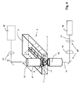
図1は、本発明による方法の可能な実施形態を説明するために、多数のサンプル1の顕微鏡での調査のための本発明に係る光学装置の例示の実施形態の詳細図を示している。 FIG. 1 shows a detailed view of an exemplary embodiment of an optical device according to the invention for microscopic examination of a large number of samples 1 to illustrate a possible embodiment of the method according to the invention.
光学装置は、検査すべきサンプル1が、サンプルホルダ2の複数のサブホルダ3内に保持されているサンプルホルダ2を含んで構成されている。サブホルダ3はそれぞれ、鎖状の直方体として具現化される。
The optical device includes a
各サブホルダ3は、寸法的に安定する埋め込み媒体から作られており、例えばアガロースまたは、(好ましくは、類似の)ゲル状の透明媒体から作られており、各サブホルダ3によって保持されたサンプル1がその中に埋め込まれている。
Each
サブホルダ3は、浸漬液(図示せず)で満たされているサンプルホルダ2の透明な受け皿内で、一般的には、好ましくは、水平面内に配置され、そして、互いに平行である。
The
サンプルホルダ2の特別な実施例と、保持されているサンプル1の特別な配置の結果として、検出対物レンズ8によって保持されている2つの偏向ミラー7を備えている偏向手段6にとって、個別の隙間が、サンプル1の両側に、有利には存在する。
And special embodiment of a
検出対物レンズ8は、サンプル1のうちの1つが、顕微鏡で検査中に、浸漬液(図示せず)に浸漬されている。検出対物レンズ8が取り付けられている偏向手段6は、顕微鏡での検査中に、浸漬液中に位置している。
Detection
偏向手段6は、線状光11が照明対物レンズ10から射出して、照明位置5に向けて、照明対物レンズ10の光軸に対してゼロ度とは異なる角度で、特に望ましくは直角で伝播するように、線状光11を偏向することを提供する。このように、照明位置5に位置されたサンプル1のレイヤーは、照明対物レンズ10によって焦点が合わせられた線状光11によって照明される。
The deflecting means 6 emits the linear light 11 from the
より明確にするために、線状光11は、図1では、部分的にしか、および概略的にしか示されていない。そして図2から図6および図7では、線状光11の経路の多少なりとも、より正確な描写が含まれている。
For more clarity, the
照明されたレイヤーから射出される、検出光、特に蛍光は、検出対物レンズ8を介して検出器(図1には示されていない)に導かれる。検出器は、2次元画像を取得するためのセンサ、例えば、CCDセンサを含むことができる。 It emitted from the illuminated layer, the detection light, in particular fluorescence, is guided to a detector through the detection objective lens 8 (not shown in Figure 1). The detector may include a sensor for acquiring a two-dimensional image, for example, a CCD sensor.
照明されたレイヤーに関する所望の画像情報が取得されると、サンプルホルダ2と、照明位置5に個別に位置されているサンプル1は、さらにサンプル1の異なるレイヤーを照明して、そして顕微鏡で検査するために、偏向された線状光11の平面に対して垂直に、および/または、照明対物レンズ10の光軸に対して平行に、互いに相対的に変位される。
Once the desired image information on the illuminated layer has been obtained, the
代わりに、偏向された線状光11で、サンプル1の異なるレイヤーを照明するためには、偏向手段6および/または、照明対物レンズ10を移動させることも可能である。例えば、照明対物レンズ10は、照明されるレイヤーを変更するために、その光軸方向に移動される。
Instead, linear light 11 deflected, in order to illuminate the different layers of the sample 1, the deflection means 6 and / or, it is also possible to move the
代わりに又は付加的には、例えば、偏向された線状光11で、サンプル1の異なるレイヤーを照明するために、偏向された線状光11の平面に対して平行に、および/または、照明対物レンズ10の光軸に対して垂直に偏向手段6を変位させることも可能である。
Alternatively or additionally, for example, to illuminate different layers of the sample 1 with the deflected linear light 11 parallel to the plane of the deflected
複数のレイヤーを順次走査することによって、サンプル照明位置5に存在している個別のサンプル1の3次元画像を取得すること、あるいは、サンプル照明位置5に位置している個別のサンプル1の3次元画像を可能にする画像データを取得することが可能となる。
By sequentially scanning a plurality of layers, it acquires a three-dimensional image of the sample lighting position 5 individual present in the
サンプル1を保持するサンプルホルダ2は、好ましくは、サンプル1の少なくとも一つがそれぞれ、サンプル照明位置5に連続的に位置されるようにサンプル照明位置に対して、特に電動式および/または自動で、移動可能に支持されている。
The
サンプルホルダ2は、好ましくは、サブホルダ3の長手方向の一方で、2つの相互に垂直な方向に、変位装置により、案内移動可能となるように配置されています。これは、二つの矢印9によって、示されている。
The
偏向手段6のための十分な隙間が、サブホルダ3の間に、外側に並んでいるために、次のサンプルが、照明位置5の中に、それぞれ搬送されていき、そして、照明対物レンズ10に対し相対的に、サンプルホルダ2を、特に水平でリニアに運動させる簡単な手段によって、顕微鏡での検査が行われる。
Sufficient clearance for deflection means 6, between the sub-holder 3, in order in a row on the outside, the next sample, in the illumination position 5, will be respectively conveyed, and, in the
有利には、同じサブホルダ3の1つのサンプル1から次のサンプル1への切り替えは、単に、排他的に、照明対物レンズ10に対して相対的なサンプルホルダ2の単一でリニアな運動を必要とするだけであり、それは、二つの矢印12によって示されている。
Advantageously, the switching from one sample 1 of the
偏向手段6と一緒の検出対物レンズ8の相対運動は、付加的に、垂直方向に、2つの矢印13によって図示されるように、1つのサブホルダ3からつぎのサブホルダ3へ切り替えるためにのみ必要とされる。
The relative movement of the deflection means 6 and with the
図2は、本発明に係る光学装置の別の例示の実施形態の詳細図を示している。 FIG. 2 shows a detailed view of another exemplary embodiment of the optical device according to the invention.
本実施形態では、サンプルホルダ2のサブホルダ3は、図1に示す実施形態のように、透明な受け皿4に配置されている。しかし、図1に示した実施形態とは異なり、サンプルホルダ2のサブホルダ3は、それぞれの中に少なくとも一つのサンプル1が配置されている、透明で、好ましくは液体の、埋め込み媒体が充填された、更なる受け皿として具現化される。更なる受け皿は、一つの共通面内でマトリクス状に、透明受け皿4内に配置されている。
In the present embodiment, the
照明位置5にサンプル1を位置決めするために、偏向手段6と一緒の検出対物レンズ8は、それぞれ、上方から、更なる受け皿の中に導入される。これは図において、湾曲した2つの矢印13によって図示されている。この実施形態では、サンプルホルダ2は、2つの相互に垂直な方向に、変位装置(図示せず)によって、案内移動可能に配置されている。これは、図面において、二つの矢印9によって示されている。
To position the sample 1 to the lighting position 5, the detection of the
図3は、本発明による光学装置のさらなる例示の実施形態の詳細図を示している。 FIG. 3 shows a detailed view of a further exemplary embodiment of the optical device according to the invention.
サンプルホルダ2は、サブホルダ3によってそれぞれのサンプル1が保持された多数のサンプル1を搬送する回転タレット14を含んで構成されている。
The
サブホルダ3は立方体状の構成であるが、このような形状に限定されるものではない。他の幾何学的形状も代わりに可能である。サブホルダ3は、それぞれ、寸法的に安定する埋め込み媒体から作られており、例えばアガロース、または、(好ましくは、類似の)ゲル状の透明媒体から作られており、少なくとも1つのサンプル1がそれぞれその中に埋め込まれている。
The
サンプル1は、順次、照明位置5に搬送され、タレット14が回転することにより、顕微鏡により検査される。 Sample 1 are sequentially conveyed to the lighting position 5, the turret 14 by rotating, is examined by microscope.
図3に示される例示の実施形態は、さらに、検査されるべきサンプル1を有するサブホルダ3を自動的にタレット14に配置し、すでに検査されたサンプル1を、このサンプル1のサブホルダ3と一緒に、タレット14から取り除くハンドリング装置15を備えている。
The example embodiment shown in FIG. 3 furthermore automatically places the
好ましくは、既に検査され、タレット14の回転によってサンプル照明位置5から既に移動されたサンプル1を、タレット14から自動的に取り除き、そして、さらに、まだ検査されていないサンプル1を、サブホルダ3と一緒に、タレット14に、特に、既に検査が行われたサンプル1が取り除かれて空になった位置に向けて搬送するハンドリング装置15が、ここでは、特に有利な態様で、供給を行う。
Preferably, the sample 1 already inspected and already moved from the sample illumination position 5 by the rotation of the turret 14 is automatically removed from the turret 14 and, furthermore, the sample 1 not yet inspected together with the
このようなやり方が有利に達成されることにより、サンプル1が連続的に、かつ継続して、絶え間なく検査されて、連続的な検査がなされる。 This is advantageously achieved in that the sample 1 is inspected continuously and continuously, continuously, so that a continuous inspection is performed.
より明確にするために、既に述べたように、線状光11が、図3に、一部のみ、概略的に示されている。加えて、より明確にするために、照明領域5におけるサブホルダ3のいくつかの輪郭線は、描かれていないか、または、部分的にのみ描かれている。
For clarity, as already mentioned, the
図4は、図1に示したサンプルキャリアと同様に構成されているサンプルキャリア2を有する、本発明の可能な光学装置の例示の実施形態を示している。しかし、サンプルキャリア2は、ただ一つのサブキャリア3を含んでいる。
FIG. 4 shows an exemplary embodiment of a possible optical device according to the invention with a
光学装置は、レーザとして具現化され、実質的に断面が円形の光束17を発光する光源16を備えている。光束17は、シリンドリカル光学素子18を用いて線状光11に整形して、照明対物レンズ10に進行する。光学要素19、例えばミラーやレンズは、光束17および線状光11を案内し、整形するために存在する。図1に示す実施形態を参照して上述したように、照明操作が実行される。
The optical device comprises a
サンプル1から射出される検出光20は、さらに光学素子21を介して検出器22に向けて進行する。
The detection light 20 emitted from the sample 1 further proceeds toward the
図5は、図4に示された実施形態に対する変形例の例示の実施形態を示している。 FIG. 5 shows an exemplary embodiment of a modification to the embodiment shown in FIG.
本実施形態では、断面が円形であって、光源16によって生成される光束17は、例えば、ガルバノミラーを含むことができるビーム偏向装置23の助けを借りて平面内で十分に迅速に偏向される。線状光11は、照明面で事実上、存在する。および/または前記照明は、サンプル1から射出される光の検出のために設けられた検出器22において、および顕微鏡の下流の評価装置において、シリンドリカル光学素子で発生した線状光11と識別することはできない。および/または取得された画像データは、連続する線状光11による照明の状況によって生成されるデータと、異ならないか、または実質的に異ならない。
In this embodiment, the
図6は、本発明の可能な光学装置の別の例示の実施形態を示している。 FIG. 6 shows another exemplary embodiment of a possible optical device of the present invention.
本例示実施形態では、サンプルホルダ2は、アガロースまたは類似の媒体からなる直方体のサブホルダ3を搬送する透明なサンプルキャリアプレート24で構成されている。
In the present exemplary embodiment, the
検査すべきサンプル1は、直方体の中に埋め込まれている。検査すべき個々のサンプル1を順次照明位置5に搬送するために、サンプルホルダ2は、サブホルダ3の長手方向の延長方向に段階的に移動される。
The sample 1 to be inspected is embedded in a rectangular parallelepiped. To carry the individual sample 1 to be examined sequentially lighting position 5, the
一つの特別な特徴は、サブホルダ3は、検査プロセスの過程で生成されるという事実である。整形手段26を備えたサブホルダ生成手段25は、このために存在している。
One special feature is the fact that the
サブホルダ生成手段25は、第1の供給管27を介して、アガロースまたは同様の透明な媒体を供給する一方で、埋め込むべきサンプル1を、第2の供給導管28を介して、供給する。
The sub-holder generating means 25 supplies the agarose or similar transparent medium via a
また、光源30と、第2の供給導管28を介して配送されるサンプル1の連続性を検出する受光部31を有する光バリア装置29が備えられる。
Further, a
成形手段26は、照明対物レンズ10に対して、固定した態様で相対配置され、サンプルキャリアプレート24に沿って移動することはない。
The shaping means 26 is arranged in a fixed manner relative to the
図7は、線状光11の可能な経路を図示している。この実施形態では、線状光11は、光束33が連続的に前後にビーム偏向装置(図示せず)により移動しているという事実によって生成される。これは湾曲した2つの矢印によって図面内で示されている。
FIG. 7 illustrates the possible paths of the
より明確にするために、図面は、この目的のみのために、簡単な「スナップショット」を示している。 For clarity, the drawings show a simple "snapshot" for this purpose only.
照明対物レンズ10から出る光束33は、前後に連続的に移動して、照明対物レンズ10によって焦点が合わせられて、偏向ミラー7に進行して、照明対物レンズ10の光軸に対してゼロ度とは異なる角度、現在の例では、90°で伝播するように、偏向ミラー7によって偏向される。
Lighting
光束33は、照明位置5に焦点32を有している。高速の前後の移動によって生成された擬似の線状光11は、結果的に、照明対物レンズ10の光軸に対して垂直な平面内に位置される。
The
照明位置5にそれぞれ位置されるサンプル1を、偏向後に好ましくは全てが同じ偏向面を伝播する複数の線状光11を用いて、別の方向(同時または連続的に)から照明することもまた可能であるが必ずしも必須ではない。しかし、より明確にするために、この場合は、図面には示されていない。
It is also possible to illuminate the sample 1 located at each of the illumination positions 5 from another direction (simultaneously or successively) with a plurality of
図8は、特殊なサンプルホルダの例示の実施形態を示している。 FIG. 8 shows an exemplary embodiment of a special sample holder.
参照番号34は、偏向手段6または偏向ミラー7とサンプルストリップまたはサブホルダ3との間で衝突が発生しないための検出対物レンズ8(概略的にのみ示す)の移動方向を示している。
サンプルストリップは、例えば、寒天から構成されており、1から複数のサンプルを含むことができる。描かれている点線35は、偏向ミラー7の移動経路を示している。
The sample strip is composed of, for example, agar and can include one to a plurality of samples. The drawn
偏向ミラー7は、サンプルストリップまたはサブホルダ3と衝突することなく、隙間または定義可能な領域に移動させることができる。原理的には、隙間または定義可能な領域は、2つの偏向ミラー7の間隔およびサンプルストリップまたはサブホルダ3の寸法に依存している。
The deflecting
加えて、2つの隣接するサブホルダ3の間の間隔は、サブホルダ3と、偏向手段6または偏向ミラー7または他の検出対物レンズ8上に配置されている他のコンポーネントとの間の衝突を回避するのに十分でなければならない。
In addition, the spacing between two
中央の点線36は、検出対物レンズ8が、サンプルストリップまたはサブホルダ3と交差することなく移動することができる安全領域38内で可能な移動経路を示している。
Central
サンプルストリップまたはサンプルホルダ3が位置することを許容する、制限された運動領域38は、灰色の背景で示されている。
The restricted
制限された運動領域38では、サンプルホルダ2と、検出対物レンズ8との間の相対運動は、とりわけ、サンプル又はサブホルダ3が、検出対物レンズ8によって損傷することがないことを常に保証するように、サブホルダ3に平行な特定の運動軌道にのみ生じることを許容する。
In
サンプルホルダ2は、統合されたキャリブレーションオブジェクトまたはマーカ39を含んでおり、それは、定義された位置での顕著なポイント、または蛍光ドット、または蛍光パターン(ビーズの房)、または顕微鏡での透過光モードにおける可視的な微細構造を備えている。
The
この種の統合されたマーカ39は、また、特に、キャリブレーションの目的を提供する。これは、照明対物レンズ10及び/又は検出対物レンズ8とサンプルホルダ2との間の相対的な位置の決定を、例えば、許容するためである。
Such an
図9は、受け皿4内で、概略長い構成のサブホルダ3を有するサンプルホルダ2の例示実施形態を示す斜視図である。サブホルダ3は、互いに実質的に平行に配置されている。
FIG. 9 is a perspective view showing an exemplary embodiment of the
検出対物レンズ(図9には図示せず)の運動軌跡37は、蛇行形状を有するか、またはサンプルホルダ2の長手方向側および横側に沿った安全領域に延びている。特別なサンプルホルダ2と一緒に、サブホルダ3の位置は、事前に定義することができる。このサブホルダ3の位置は、サンプルが特別なサンプルホルダ2上で検出されたことをシステムが認識したときに、メモリから読み出される。
図10は、受け皿4内で、サブホルダ3を有するサンプルホルダ2のさらなる例示実施形態を示す斜視図である。
FIG. 10 is a perspective view showing a further exemplary embodiment of the
サブホルダ3は、異なる長さを有することができ、互いに実質的に平行に配置されている。しかしながら、サブホルダ3の長手方向は、他の方向(図示せず)に配向することができ、また、平行でない態様で配置することもできる。
The
図10は、検出対物レンズ8(図10では示せず)の最適化された様式で算出された運動経路37を示している。これは、検出対物レンズ8/偏向手段6とサンプル1との間の衝突を回避するようにしながらも、検出対物レンズ8の最短の運動経路および/または最短の検出期間とすることができる。
Figure 10 shows the
例えば、1つのサブホルダ3の終点40と、つぎのサブホルダ3の出発点41との間の最短の運動経路は、制限された運動領域38内に確認される。終点42が、制限された運動領域38の端部の近くに位置されている場合は、次のサブホルダ3は、安全領域37を介して移動される。
For example, the shortest movement path between the
Claims (28)
a.サンプルの少なくとも一つが、それぞれ連続的にサンプル照明位置に位置決め可能であるように、前記サンプル照明位置に対して、相対的に電動式または自動で移動可能なサンプルホルダにサンプルを配置し、偏向手段のための隙間が、現在、前記サンプル照明位置に位置しているサンプルに隣接しており、
b.照明対物レンズによって線状光の焦点を合わせ、
c.前記線状光が前記照明対物レンズを通過した後に、前記偏向手段によって、前記線状光が前記照明対物レンズの光軸に対してゼロ度とは異なる角度、または10度よりも大きい角度で、または直角で伝播し、前記サンプル照明位置に焦点を有するように前記線状光を偏向し、
d.前記サンプルホルダに保持されたサンプルを、前記サンプル照明位置に連続的に位置決めし、前記サンプル照明位置にそれぞれ位置されるサンプルから出される検出光を検出し、
e.前記サンプルを、少なくとも一つの直列に、前記サンプルホルダに保持し、または、
f.前記サンプルを、環状の列若しくは湾曲した列で、前記サンプルホルダに保持し、
g.前記サンプルホルダを、3つの異なる方向または、互いに直交する方向に変位させ、
それぞれ使用される前記サンプルホルダの種類は、自動的に認識され、
前記サンプル照明位置における前記サンプルの連続的な位置決めは、前記認識されたサンプルホルダの種類を考慮して、および/または前記認識されたサンプルホルダの種類に関連付けられた、および/またはソフトウェアのメモリに記憶されている位置変更ルーチンを使用して達成される、
ことを特徴とする方法。 A method for inspecting a plurality of samples with a microscope, comprising the following steps:
a. Deflecting means for arranging the sample in a motorized or automatically movable sample holder relative to the sample illumination position so that at least one of the samples can each be continuously positioned at the sample illumination position; A gap for the sample that is currently located at the sample lighting position,
b. Focus the linear light with the illumination objective lens,
c. After the linear light has passed through the illumination objective, the deflecting means causes the linear light to be at an angle different from zero degrees with respect to the optical axis of the illumination objective, or at an angle greater than 10 degrees, Or propagating at a right angle, deflecting the linear light to have a focus at the sample illumination location,
d. The sample held in the sample holder is continuously positioned at the sample illumination position, and detects detection light emitted from the sample located at each of the sample illumination positions,
e. Holding said sample in said sample holder in at least one series, or
f. Holding the sample in an annular or curved row in the sample holder,
g. Displacing the sample holder in three different directions or directions orthogonal to each other ,
The type of sample holder used for each is automatically recognized,
The continuous positioning of the sample at the sample illumination location may take into account the recognized sample holder type and / or be associated with the recognized sample holder type and / or in software memory. Achieved using a stored repositioning routine,
A method comprising:
ことを特徴とする請求項1記載の方法。 The method according to claim 1, wherein the sample is held in a matrix and / or in a common plane by the sample holder.
b.前記サンプルホルダは、少なくとも一つのサンプルがそれぞれ保持されている複数のサブホルダを含んでいる、または、
c.前記サンプルホルダは、少なくとも一つのサンプルが、またはサンプルの列が、それぞれ保持されている少なくとも一つの鎖状のサブホルダを含んでいる、または、
d.前記サンプルホルダは、共通の平面および/または互いに平行に配向された複数の鎖状のサブホルダを含んでいる、または、
e.前記サンプルホルダは、前記サンプルの少なくとも一つがそれぞれ保持されている複数の立方体形状のサブホルダを含んでいる、または、
f.前記サンプルホルダは、少なくとも一つのサンプルがそれぞれ配置されている受け皿として具現化されるサブホルダを含んでいる、または、
g.前記サンプルホルダは、前記サンプルの少なくとも一つが保持されているか、または前記サンプルの複数個が配置されているまたは並列させられている管を含んでいる、または、
h.前記サンプル照明位置は、前記照明対物レンズの外側に配置されているが、前記照明対物レンズの延長された光軸上に配置されている、
ことを特徴とする請求項1または2記載の方法。 a. one or more of the samples is held in a sub-holder of the sample holder; or
b. the sample holder includes a plurality of sub-holders each holding at least one sample; or
c. the sample holder comprises at least one chain-like sub-holder in which at least one sample or a row of samples is respectively held, or
d. said sample holder comprises a plurality of chain-like sub-holders oriented in a common plane and / or parallel to each other, or
e. said sample holder comprises a plurality of cubic sub-holders each holding at least one of said samples, or
f. said sample holder comprises a sub-holder embodied as a saucer on which at least one sample is respectively arranged, or
g. the sample holder comprises a tube in which at least one of the samples is held or in which a plurality of the samples are arranged or juxtaposed, or
h. the sample illumination position is located outside the illumination objective, but on the extended optical axis of the illumination objective;
3. The method according to claim 1, wherein the method comprises:
b.既に検査されて、既に前記サンプル照明位置から遠ざけられている前記サンプルが、前記サンプルホルダから取り除かれ、そして、検査すべき更なるサンプルが前記サンプルホルダに、または、空となった前記サンプルホルダの位置に引き渡される、
ことを特徴とする請求項1から4のいずれか一項に記載の方法。 a. the sample already inspected and already removed from the sample illumination position is removed from the sample holder, or
b. the sample which has already been examined and which has already been moved away from the sample illumination position has been removed from the sample holder and the further sample to be examined has been emptied into the sample holder or emptied Delivered to the position of the holder,
A method according to any one of claims 1 to 4, characterized in that:
b.前記サンプルホルダは、検査すべき次のサンプルを、前記サンプル照明位置に、それぞれ位置決めするために、前記照明対物レンズの光軸の周りに、または前記照明対物レンズの光軸に平行な軸の周りに回転される、または、
c.前記サンプルホルダは、検査すべき次のサンプルを、前記サンプル照明位置に、それぞれ位置決めするために、前記サンプル照明位置に対して相対的に少なくとも一つの方向に直線的に変位される、または、
d.前記サンプルホルダを2つの異なる方向または、互いに直交する方向に変位可能な変位装置が存在している、
ことを特徴とする請求項1から5のいずれか一項に記載の方法。 the sample holder is rotated to position the next sample to be inspected at the sample illumination position, respectively; or
b. the sample holder has an axis around or parallel to the optical axis of the illumination objective for respectively positioning the next sample to be examined at the sample illumination position, Rotated around, or
c. the sample holder is linearly displaced in at least one direction relative to the sample illumination position to position a next sample to be examined at the sample illumination position, respectively; or ,
d. there is a displacement device capable of displacing the sample holder in two different directions or directions orthogonal to each other;
A method according to any one of claims 1 to 5, characterized in that:
または、
b.前記サンプル照明位置と前記偏向手段が配置されている平面の中に、サンプルを前記サンプル照明位置に搬送して、そこから遠ざけることができる少なくとも一つの領域の余地がある、
ことを特徴とする請求項1から6までのいずれか一項に記載の方法。 a. The deflecting means and the sample located at the sample illumination position are arranged in a common plane, and the deflecting means moves the sample located at the sample illumination position on one side in this plane. Or covering on two opposite sides,
Or
b. in the plane in which the sample illumination position and the deflecting means are arranged, there is room for at least one area where a sample can be transported to and away from the sample illumination position;
The method according to any one of claims 1 to 6, characterized in that:
b.前記偏向手段は、前記照明対物レンズに移動可能に取り付けられている、または、
c.前記偏向手段は、前記検出対物レンズに移動可能に取り付けられている、
ことを特徴とする請求項12又は13に記載の方法。 a. the illumination objective lens and the deflection means are arranged so as to be movable relative to each other; or
b. the deflecting means is movably mounted on the illumination objective, or
c. the deflecting means is movably attached to the detection objective lens;
14. A method according to claim 12 or claim 13 , wherein:
線状光の焦点を合わせて出る照明対物レンズと、
前記線状光を前記サンプルに向けて偏向する偏向手段と、
を備えた光学装置であって、
前記偏向手段のための隙間が、現在、前記サンプル照明位置に位置しているサンプルにそれぞれ隣接して存在しており、
前記偏向手段は、前記線状光が、前記照明対物レンズの光軸に対してゼロ度とは異なる角度、または直角で伝播するように、前記照明対物レンズから出される前記線状光を偏向するものであり、前記サンプル照明位置にそれぞれ位置されるサンプルから出される検出光を検出する検出器を備え、
前記サンプルホルダは、前記サンプルを少なくとも一つの直列に、または環状の列若しくは湾曲した列で保持しており、
前記サンプルホルダを3つの異なる方向または、互いに直交する方向に変位させる変位装置を備えており、
それぞれ使用されるサンプルホルダの種類を、自動的に認識する制御装置を備え、
前記サンプル照明位置における前記サンプルの連続的な位置決めを、前記認識されたサンプルホルダの種類を考慮して、および/または前記認識されたサンプルホルダの種類に関連付けられた、および/またはソフトウェアのメモリに記憶されている位置変更ルーチンを使用して達成する
ことを特徴とする光学装置。 Holding a plurality of samples, each motorized and / or automatically movable relative to the sample illumination position such that at least one of the samples is each continuously positionable at the sample illumination position; A supported or movable sample holder;
An illumination objective lens that focuses and outputs the linear light;
Deflecting means for deflecting the linear light toward the sample,
An optical device comprising:
Gaps for the deflecting means are present respectively adjacent to the sample located at the sample illumination position,
The deflecting unit deflects the linear light emitted from the illumination objective lens such that the linear light propagates at an angle different from zero degrees with respect to the optical axis of the illumination objective lens, or at a right angle. And a detector for detecting detection light emitted from a sample located at each of the sample illumination positions,
The sample holder holds the samples in at least one series or in an annular or curved row;
A displacement device for displacing the sample holder in three different directions or directions orthogonal to each other ,
Equipped with a control device that automatically recognizes the type of sample holder used,
A continuous positioning of the sample at the sample illumination location is performed in consideration of the recognized sample holder type and / or associated with the recognized sample holder type and / or in software memory. An optical device, achieved using a stored repositioning routine .
ことを特徴とする請求項15に記載の光学装置。 The optical device according to claim 15 , wherein the sample is held in a matrix and / or in a common plane by the sample holder.
b.前記サンプルホルダは、少なくとも一つのサンプルがそれぞれ保持されている複数のサブホルダを含んでいる、または、
c.前記サンプルホルダは、少なくとも一つのサンプルが、または、サンプルの列が、それぞれ保持されている少なくとも一つの鎖状のサブホルダを含んでいる、または、
d.前記サンプルホルダは、共通の平面および/または互いに平行に配向された複数の鎖状のサブホルダを含んでいる、または、
e.前記サンプルホルダは、前記サンプルの少なくとも一つがそれぞれ保持されている複数の立方体形状のサブホルダを含んでいる、または、
f.前記サンプルホルダは、少なくとも一つのサンプルがそれぞれ配置されている受け皿として具現化されるサブホルダを含んでいる、または、
g.前記サンプルホルダは、前記サンプルの少なくとも一つが保持されているか、または前記サンプルの複数個が配置されているまたは並列させられている管を含んでいる、または、
h.前記サンプル照明位置は、前記照明対物レンズの外側に配置されているが、前記照明対物レンズの延長された光軸上に配置されている
ことを特徴とする請求項15または16に記載の光学装置。 a. one or more of the samples is held in a sub-holder of a sample holder, or
b. the sample holder includes a plurality of sub-holders each holding at least one sample; or
c. said sample holder comprises at least one chain-like sub-holder, wherein at least one sample or a row of samples is respectively retained, or
d. said sample holder comprises a plurality of chain-like sub-holders oriented in a common plane and / or parallel to each other, or
e. said sample holder comprises a plurality of cubic sub-holders each holding at least one of said samples, or
f. said sample holder comprises a sub-holder embodied as a saucer on which at least one sample is respectively arranged, or
g. the sample holder comprises a tube in which at least one of the samples is held or in which a plurality of the samples are arranged or juxtaposed, or
h. The sample illumination position, wherein at lighting is arranged outside the objective lens, according to claim 15 or 16, characterized in that disposed in extended on the optical axis of the illumination objective lens Optical device.
b.既に検査されて、既に前記サンプル照明位置から遠ざけられている前記サンプルを、前記サンプルホルダから取り除き、そして、検査すべき更なるサンプルを前記サンプルホルダに、または、空となった前記サンプルホルダの位置に引き渡すハンドリング装置を備える、
ことを特徴とする請求項17から18のいずれか一項に記載の光学装置。 a. comprising a handling device for removing from the sample holder the sample that has been inspected and has already been moved away from the sample illumination position, or
b. remove from the sample holder the sample that has already been inspected and has been moved away from the sample illumination position, and further sample to be inspected in the sample holder or the empty sample holder Equipped with a handling device to be delivered to the position of
The optical device according to any one of claims 17 to 18 , wherein:
b.検査すべき次のサンプルを、前記サンプル照明位置に、それぞれ位置決めするために、前記照明対物レンズの光軸の周りに、または前記照明対物レンズの光軸に平行な軸の周りに、前記サンプルホルダを、回転させる制御装置を備える、または、
c.検査すべき次のサンプルを、前記サンプル照明位置に、それぞれ位置決めするために、前記サンプル照明位置に対して相対的に少なくとも一つの方向に変位する前記サンプルホルダを、変位装置によって直線的に変位させる制御装置を備える、または、
d.前記サンプルホルダが、2つの異なる方向または、互いに直交する方向に変位させることができる変位装置を備える
ことを特徴とする請求項15から19のいずれか一項に記載の光学装置。 a control device for rotating the rotatably supported sample holder to position the next sample to be inspected at each of the sample illumination positions, or
b. around the optical axis of the illumination objective or around an axis parallel to the optical axis of the illumination objective, for positioning the next sample to be examined at the sample illumination position, respectively; A control device for rotating the sample holder, or
c. The following sample to be examined, the sample illumination position, in order to position respectively, the sample holder to be displaced relatively at least one direction relative to the sample illumination position, linearly by a displacement device Equipped with a control device for displacing, or
20. The optical device according to any one of claims 15 to 19 , wherein the sample holder comprises a displacement device that can be displaced in two different directions or directions orthogonal to each other.
または、
b.前記サンプル照明位置と前記偏向手段が配置されている平面の中に、サンプルが前記サンプル照明位置に搬送されて、そこから遠ざけることができる少なくとも一つの領域の余地がある
ことを特徴とする請求項15から20のいずれか一項に記載の光学装置。 a. The deflecting means and the sample located at the sample illumination position are arranged in a common plane, and the deflecting means moves the sample located at the sample illumination position on one side in this plane. Or it covers on two opposite sides.
Or
b. in the plane in which the sample illumination position and the deflection means are arranged, there is room for at least one area in which a sample can be transported to and away from the sample illumination position. The optical device according to any one of claims 15 to 20 .
前記サンプルから出る前記検出光は、前記検出対物レンズを介して進行、および/または、検出対物レンズにコリメートされる、請求項15から25のいずれか一項に記載の光学装置。 A detection objective lens for guiding the detection light to the detector,
26. The optical device according to any one of claims 15 to 25 , wherein the detection light emerging from the sample travels through the detection objective and / or is collimated to the detection objective.
b.前記偏向手段は、前記照明対物レンズに移動可能に取り付けられている、または、
c.前記偏向手段は、前記検出対物レンズに移動可能に取り付けられている、
ことを特徴とする請求項26又は27に記載の光学装置。 a. the illumination objective lens and the deflection means are arranged so as to be movable relative to each other; or
b. the deflecting means is movably mounted on the illumination objective, or
c. the deflecting means is movably attached to the detection objective lens;
The optical device according to claim 26 or 27 , wherein:
Applications Claiming Priority (3)
| Application Number | Priority Date | Filing Date | Title |
|---|---|---|---|
| DE102013211426.5A DE102013211426A1 (en) | 2013-06-18 | 2013-06-18 | Method and optical device for microscopically examining a plurality of samples |
| DE102013211426.5 | 2013-06-18 | ||
| PCT/EP2014/062907 WO2014202704A1 (en) | 2013-06-18 | 2014-06-18 | Method and optical device for microscopically examining a multiplicity of specimens |
Publications (3)
| Publication Number | Publication Date |
|---|---|
| JP2016535861A JP2016535861A (en) | 2016-11-17 |
| JP2016535861A5 JP2016535861A5 (en) | 2019-03-07 |
| JP6632523B2 true JP6632523B2 (en) | 2020-01-22 |
Family
ID=51022841
Family Applications (1)
| Application Number | Title | Priority Date | Filing Date |
|---|---|---|---|
| JP2016520481A Active JP6632523B2 (en) | 2013-06-18 | 2014-06-18 | Optical apparatus and method for inspecting multiple samples with a microscope |
Country Status (5)
| Country | Link |
|---|---|
| US (1) | US10458899B2 (en) |
| EP (1) | EP3011379B1 (en) |
| JP (1) | JP6632523B2 (en) |
| DE (1) | DE102013211426A1 (en) |
| WO (1) | WO2014202704A1 (en) |
Families Citing this family (17)
| Publication number | Priority date | Publication date | Assignee | Title |
|---|---|---|---|---|
| DE102013213781A1 (en) * | 2013-03-20 | 2014-09-25 | Leica Microsystems Cms Gmbh | Method and optical arrangement for manipulating and imaging a microscopic sample |
| DE102013226277A1 (en) * | 2013-12-17 | 2015-06-18 | Leica Microsystems Cms Gmbh | Method and device for examining a sample by means of optical projection tomography |
| LU92505B1 (en) * | 2014-07-22 | 2016-01-25 | Leica Microsystems | METHOD AND DEVICE FOR MICROSCOPICALLY EXAMINING A SAMPLE |
| US11085901B2 (en) * | 2014-08-19 | 2021-08-10 | Dan Slater | Acoustical microscope |
| DE102015114756B4 (en) * | 2014-09-25 | 2021-07-22 | Leica Microsystems Cms Gmbh | Mirror device |
| LU93022B1 (en) * | 2016-04-08 | 2017-11-08 | Leica Microsystems | Method and microscope for examining a sample |
| US10310248B2 (en) * | 2016-08-18 | 2019-06-04 | Olympus Corporation | Microscope including a medium container containing an immersion medium in which a specimen container containing an immersion medium and a sample is immersed |
| US10690898B2 (en) * | 2016-09-15 | 2020-06-23 | Molecular Devices (Austria) GmbH | Light-field microscope with selective-plane illumination |
| JP2018096703A (en) * | 2016-12-08 | 2018-06-21 | オリンパス株式会社 | Microplate and microscopic system |
| LU100024B1 (en) * | 2017-01-20 | 2018-07-30 | Leica Microsystems | A method for sequentially examining a plurality of samples, sample carrier unit, and light sheet microscopic imaging unit |
| EP3495865A1 (en) * | 2017-12-07 | 2019-06-12 | European Molecular Biology Laboratory | A sample holder for imaging a plurality of samples |
| JP7329113B2 (en) * | 2018-04-09 | 2023-08-17 | 浜松ホトニクス株式会社 | Sample observation device |
| JP7207860B2 (en) | 2018-04-09 | 2023-01-18 | 浜松ホトニクス株式会社 | Sample observation device |
| DE102018128264B4 (en) * | 2018-11-12 | 2020-08-20 | Leica Microsystems Cms Gmbh | Light sheet microscope |
| DE102018222271A1 (en) * | 2018-12-19 | 2020-06-25 | Carl Zeiss Microscopy Gmbh | Method for operating a sample chamber for microscopic imaging and device and sample chamber |
| JP7108564B2 (en) * | 2019-03-06 | 2022-07-28 | アンリツ株式会社 | X-ray inspection device |
| EP4341664A1 (en) * | 2021-05-19 | 2024-03-27 | Leica Microsystems CMS GmbH | Method and apparatus for imaging a biological sample |
Family Cites Families (12)
| Publication number | Priority date | Publication date | Assignee | Title |
|---|---|---|---|---|
| US5002377A (en) | 1988-07-07 | 1991-03-26 | City Of Hope | Multi-specimen slides for immunohistologic procedures |
| DE19950225A1 (en) | 1998-10-24 | 2000-05-18 | Leica Microsystems | Arrangement for the optical scanning of an object |
| US20030002148A1 (en) | 1998-10-24 | 2003-01-02 | Johann Engelhardt | Arrangement for optically scanning an object |
| DE10257423A1 (en) | 2002-12-09 | 2004-06-24 | Europäisches Laboratorium für Molekularbiologie (EMBL) | Microscope used in molecular biology comprises a focussing arrangement producing an extended planar object illumination region, a detection device, and a movement arrangement |
| WO2005036451A1 (en) * | 2003-10-08 | 2005-04-21 | Lifespan Biosciences, Inc. | Automated microspcope slide tissue sample mapping and image acquisition |
| DE102004034957A1 (en) | 2004-07-16 | 2006-02-02 | Carl Zeiss Jena Gmbh | Arrangement for microscopic observation and / or detection and use |
| WO2007065711A1 (en) * | 2005-12-09 | 2007-06-14 | Europäisches Laboratorium für Molekularbiologie (EMBL) | Miscroscope specimen holder |
| CA2815953A1 (en) * | 2010-11-08 | 2012-05-18 | Reametrix Inc. | Sample assembly for a measurement device |
| DE102011000835C5 (en) * | 2011-02-21 | 2019-08-22 | Leica Microsystems Cms Gmbh | Scanning microscope and method for light microscopic imaging of an object |
| US9446411B2 (en) * | 2011-02-24 | 2016-09-20 | Reametrix, Inc. | Sample assembly for a measurement device |
| US9316824B2 (en) * | 2011-03-04 | 2016-04-19 | The United States Of America, As Represented By The Secretary, Department Of Health And Human Services | Optomechanical module for converting a microscope to provide selective plane illumination microscopy |
| DE102011054914A1 (en) * | 2011-10-28 | 2013-05-02 | Leica Microsystems Cms Gmbh | Method and arrangement for illuminating a sample |
-
2013
- 2013-06-18 DE DE102013211426.5A patent/DE102013211426A1/en active Pending
-
2014
- 2014-06-18 WO PCT/EP2014/062907 patent/WO2014202704A1/en active Application Filing
- 2014-06-18 EP EP14733586.3A patent/EP3011379B1/en active Active
- 2014-06-18 US US14/899,157 patent/US10458899B2/en active Active
- 2014-06-18 JP JP2016520481A patent/JP6632523B2/en active Active
Also Published As
| Publication number | Publication date |
|---|---|
| US20160153892A1 (en) | 2016-06-02 |
| DE102013211426A1 (en) | 2014-12-18 |
| EP3011379B1 (en) | 2021-08-18 |
| US10458899B2 (en) | 2019-10-29 |
| EP3011379A1 (en) | 2016-04-27 |
| WO2014202704A1 (en) | 2014-12-24 |
| JP2016535861A (en) | 2016-11-17 |
Similar Documents
| Publication | Publication Date | Title |
|---|---|---|
| JP6632523B2 (en) | Optical apparatus and method for inspecting multiple samples with a microscope | |
| JP2016535861A5 (en) | ||
| JP7055793B2 (en) | Brightfield microscope with selective planar illumination | |
| CN108700518B (en) | Automated analysis tool for biological samples | |
| JP6685977B2 (en) | microscope | |
| EP2801855B1 (en) | A microscope module for imaging a sample | |
| CN107526156B (en) | Light sheet microscope and method for operating a light sheet microscope | |
| US8350230B2 (en) | Method and optical assembly for analysing a sample | |
| US10634888B2 (en) | Light microscope with inner focusing objective and microscopy method for examining a plurality of microscopic objects | |
| JP6676613B2 (en) | Method and apparatus for microscopic inspection of a sample | |
| US7982170B2 (en) | Microscope system | |
| JP2013519908A (en) | Scanning microscope and method for optically scanning one or more samples | |
| ES2928577T3 (en) | 2D and 3D Fixed Z-Scan | |
| CN111093830A (en) | Object picking device with imaging-based pipette tip positioning | |
| JP2022000648A (en) | High-throughput biochemical screening | |
| JP2018128604A (en) | Microscope device | |
| CN105319695A (en) | Transmitted-light microscope and method for transmitted-light microscopy | |
| CN111492295A (en) | Microscope for imaging a sample and sample holder for such a microscope | |
| EP3435136B1 (en) | Multi-surface image acquisition system | |
| JP6602855B2 (en) | Mirror device | |
| CN116802463A (en) | Universal multi-functional detection system for microwell plates with confocal imaging | |
| US20230251480A1 (en) | Method and apparatus for localizing objects by means of a light sheet | |
| JP2015203708A (en) | Microscope device |
Legal Events
| Date | Code | Title | Description |
|---|---|---|---|
| A521 | Request for written amendment filed |
Free format text: JAPANESE INTERMEDIATE CODE: A523 Effective date: 20160216 |
|
| A621 | Written request for application examination |
Free format text: JAPANESE INTERMEDIATE CODE: A621 Effective date: 20170619 |
|
| RD03 | Notification of appointment of power of attorney |
Free format text: JAPANESE INTERMEDIATE CODE: A7423 Effective date: 20180509 |
|
| A131 | Notification of reasons for refusal |
Free format text: JAPANESE INTERMEDIATE CODE: A131 Effective date: 20180709 |
|
| A601 | Written request for extension of time |
Free format text: JAPANESE INTERMEDIATE CODE: A601 Effective date: 20181005 |
|
| A601 | Written request for extension of time |
Free format text: JAPANESE INTERMEDIATE CODE: A601 Effective date: 20181205 |
|
| A524 | Written submission of copy of amendment under article 19 pct |
Free format text: JAPANESE INTERMEDIATE CODE: A524 Effective date: 20190109 |
|
| A02 | Decision of refusal |
Free format text: JAPANESE INTERMEDIATE CODE: A02 Effective date: 20190624 |
|
| A521 | Request for written amendment filed |
Free format text: JAPANESE INTERMEDIATE CODE: A523 Effective date: 20191023 |
|
| A911 | Transfer to examiner for re-examination before appeal (zenchi) |
Free format text: JAPANESE INTERMEDIATE CODE: A911 Effective date: 20191031 |
|
| TRDD | Decision of grant or rejection written | ||
| A01 | Written decision to grant a patent or to grant a registration (utility model) |
Free format text: JAPANESE INTERMEDIATE CODE: A01 Effective date: 20191118 |
|
| A61 | First payment of annual fees (during grant procedure) |
Free format text: JAPANESE INTERMEDIATE CODE: A61 Effective date: 20191210 |
|
| R150 | Certificate of patent or registration of utility model |
Ref document number: 6632523 Country of ref document: JP Free format text: JAPANESE INTERMEDIATE CODE: R150 |
|
| R250 | Receipt of annual fees |
Free format text: JAPANESE INTERMEDIATE CODE: R250 |
|
| R250 | Receipt of annual fees |
Free format text: JAPANESE INTERMEDIATE CODE: R250 |