DE102015114756B4 - Mirror device - Google Patents
Mirror device Download PDFInfo
- Publication number
- DE102015114756B4 DE102015114756B4 DE102015114756.4A DE102015114756A DE102015114756B4 DE 102015114756 B4 DE102015114756 B4 DE 102015114756B4 DE 102015114756 A DE102015114756 A DE 102015114756A DE 102015114756 B4 DE102015114756 B4 DE 102015114756B4
- Authority
- DE
- Germany
- Prior art keywords
- mirror
- holding component
- fastened
- deflection
- deflecting
- Prior art date
- Legal status (The legal status is an assumption and is not a legal conclusion. Google has not performed a legal analysis and makes no representation as to the accuracy of the status listed.)
- Active
Links
- 238000000386 microscopy Methods 0.000 claims abstract description 9
- 230000003287 optical effect Effects 0.000 claims description 46
- 238000005286 illumination Methods 0.000 claims description 21
- 238000001514 detection method Methods 0.000 claims description 16
- 239000000463 material Substances 0.000 claims description 4
- 230000013011 mating Effects 0.000 claims description 4
- 235000015097 nutrients Nutrition 0.000 claims description 4
- 230000007797 corrosion Effects 0.000 claims description 2
- 238000005260 corrosion Methods 0.000 claims description 2
- 239000002184 metal Substances 0.000 claims description 2
- 229910001220 stainless steel Inorganic materials 0.000 claims description 2
- 239000010935 stainless steel Substances 0.000 claims description 2
- 238000013461 design Methods 0.000 description 8
- 238000000034 method Methods 0.000 description 7
- 230000005284 excitation Effects 0.000 description 6
- 238000004519 manufacturing process Methods 0.000 description 6
- 238000005516 engineering process Methods 0.000 description 5
- 238000002474 experimental method Methods 0.000 description 5
- 230000005540 biological transmission Effects 0.000 description 3
- 230000000694 effects Effects 0.000 description 3
- 230000002186 photoactivation Effects 0.000 description 3
- 238000002679 ablation Methods 0.000 description 2
- 238000006243 chemical reaction Methods 0.000 description 2
- 238000002376 fluorescence recovery after photobleaching Methods 0.000 description 2
- 238000003384 imaging method Methods 0.000 description 2
- 238000007654 immersion Methods 0.000 description 2
- 238000011835 investigation Methods 0.000 description 2
- 239000003921 oil Substances 0.000 description 2
- 210000001747 pupil Anatomy 0.000 description 2
- 238000002310 reflectometry Methods 0.000 description 2
- 238000010521 absorption reaction Methods 0.000 description 1
- 238000004061 bleaching Methods 0.000 description 1
- 239000012141 concentrate Substances 0.000 description 1
- 238000005520 cutting process Methods 0.000 description 1
- 238000006073 displacement reaction Methods 0.000 description 1
- 238000009826 distribution Methods 0.000 description 1
- 239000012530 fluid Substances 0.000 description 1
- 238000000799 fluorescence microscopy Methods 0.000 description 1
- 239000007850 fluorescent dye Substances 0.000 description 1
- 230000003760 hair shine Effects 0.000 description 1
- 238000009434 installation Methods 0.000 description 1
- 239000007788 liquid Substances 0.000 description 1
- 238000012576 optical tweezer Methods 0.000 description 1
- 238000012545 processing Methods 0.000 description 1
- 230000000717 retained effect Effects 0.000 description 1
- 239000000126 substance Substances 0.000 description 1
- 238000012360 testing method Methods 0.000 description 1
- XLYOFNOQVPJJNP-UHFFFAOYSA-N water Substances O XLYOFNOQVPJJNP-UHFFFAOYSA-N 0.000 description 1
Images


Classifications
-
- G—PHYSICS
- G02—OPTICS
- G02B—OPTICAL ELEMENTS, SYSTEMS OR APPARATUS
- G02B21/00—Microscopes
- G02B21/06—Means for illuminating specimens
-
- G—PHYSICS
- G02—OPTICS
- G02B—OPTICAL ELEMENTS, SYSTEMS OR APPARATUS
- G02B7/00—Mountings, adjusting means, or light-tight connections, for optical elements
- G02B7/18—Mountings, adjusting means, or light-tight connections, for optical elements for prisms; for mirrors
- G02B7/182—Mountings, adjusting means, or light-tight connections, for optical elements for prisms; for mirrors for mirrors
-
- G—PHYSICS
- G02—OPTICS
- G02B—OPTICAL ELEMENTS, SYSTEMS OR APPARATUS
- G02B21/00—Microscopes
- G02B21/36—Microscopes arranged for photographic purposes or projection purposes or digital imaging or video purposes including associated control and data processing arrangements
- G02B21/362—Mechanical details, e.g. mountings for the camera or image sensor, housings
Landscapes
- Physics & Mathematics (AREA)
- General Physics & Mathematics (AREA)
- Optics & Photonics (AREA)
- Chemical & Material Sciences (AREA)
- Analytical Chemistry (AREA)
- Engineering & Computer Science (AREA)
- Multimedia (AREA)
- Microscoopes, Condenser (AREA)
Abstract
Spiegelvorrichtung (17) zum Umlenken von Beleuchtungslicht bei der SPIM-Mikroskopie, gekennzeichnet durch ein Haltebauteil (1), das ein Verbindungselement (2) zum Befestigen des Haltebauteils an einem Mikroskopobjektiv (18) aufweist, wobei an dem Haltebauteil wenigstens ein Umlenkspiegel (10) wieder lösbar befestigt ist, wobei das Haltebauteil mehrere Aufnahmen (4) aufweist, in und/oder an denen jeweils ein Umlenkspiegel befestigt ist oder befestigbar ist, wobei jede Aufnahme wenigstens einen Anschlag (12, 13) aufweist, der im Zusammenwirken mit einem Gegenanschlag (14, 15) eines Umlenkspiegels jeweils eine eindeutige Befestigungsposition des Umlenkspiegels definiert.Mirror device (17) for deflecting illuminating light in SPIM microscopy, characterized by a holding component (1) which has a connecting element (2) for attaching the holding component to a microscope objective (18), with at least one deflecting mirror (10) on the holding component is releasably fastened again, the holding component having several receptacles (4) in and / or on each of which a deflecting mirror is fastened or can be fastened, each receptacle having at least one stop (12, 13) which, in cooperation with a counter stop ( 14, 15) of a deflection mirror each define a unique fastening position of the deflection mirror.
Description
Die Erfindung betrifft eine Spiegelvorrichtung zum Umlenken von Beleuchtungslicht bei der SPIM-Mikroskopie.The invention relates to a mirror device for deflecting illuminating light in SPIM microscopy.
Die Erfindung betrifft außerdem eine optische Vorrichtung, eine Anordnung zum Beleuchten einer Probe bei der SPIM-Mikroskopie, sowie ein Mikroskop mit einer solchen Spiegelvorrichtung.The invention also relates to an optical device, an arrangement for illuminating a sample in SPIM microscopy, and a microscope with such a mirror device.
Die SPIM-Technik (Single Plane Illumination Microscopy), bei der eine schichtweise Beleuchtung der Probe erfolgt, erlaubt eine schnellere und probenschonendere Erfassung von Bilddaten, als beispielsweise bei einer punktweisen Abtastung einer Probe. Ein bekanntes Einsatzgebiet der SPIM-Technologie ist der Bereich der Fluoreszenz-Mikroskopie, wobei Fluorophore in der Probe mit Laserlicht angeregt werden. Bei der SPIM-Technologie findet hierbei eine Anregung nur in einer von einem Beleuchtungslichtblatt (auch „Lichtstreifen“ genannt) durchstrahlten Ebene statt. Eine Schädigung der Probe durch Beleuchtungslicht in anderen Ebenen ist hierdurch vermieden.The SPIM technology (Single Plane Illumination Microscopy), in which the sample is illuminated in layers, enables faster and more gentle acquisition of image data than, for example, point-by-point scanning of a sample. A well-known area of application for SPIM technology is in fluorescence microscopy, where fluorophores in the sample are excited with laser light. With SPIM technology, excitation takes place only in a plane through which an illuminating light sheet (also known as a “light strip”) shines through. This avoids damage to the sample by illuminating light in other planes.
Ein nach dem SPIM-Prinzip arbeitendes Mikroskop (Selective Plane Illumination Microscope) ist beispielsweise in Lindek et al;
Eine nach dem SPIM-Verfahren arbeitende optische Vorrichtung ist in
Aus
Die
Die
Aus
Derartige Umlenkeinrichtungen wurden bislang aufwändig einstückig hergestellt und sind zumeist sehr umständlich gehaltert. Insbesondere sind die bislang hergestellten Umlenkeinrichtungen zumeist mit sehr aufwändigen und für eine Serienfertigung nicht geeigneten Fertigungsverfahren hergestellt.Such deflection devices have hitherto been produced in a complex, one-piece manner and are mostly held in a very cumbersome manner. In particular, the deflection devices produced so far are mostly very complex and for one Series production not made suitable manufacturing processes.
Es ist daher die Aufgabe der vorliegenden Erfindung eine Spiegelvorrichtung der eingangs genannten Art anzugeben, die einfach, flexibel und zuverlässig handhabbar ist und die darüber hinaus einfach, insbesondere auch mit Serienherstellungsverfahren, herstellbar ist.It is therefore the object of the present invention to specify a mirror device of the type mentioned at the outset which can be handled simply, flexibly and reliably and which, moreover, can be produced simply, in particular also using mass production methods.
Die Aufgabe wird durch eine Spiegelvorrichtung gemäß Patentanspruch 1 gelöst.The object is achieved by a mirror device according to
Die erfindungsgemäße Spiegelvorrichtung hat den ganz besonderen Vorteil, dass sie einfach und zuverlässig an einem Mikroskopobjektiv und/oder in einer optischen Anordnung zum Beleuchten einer Probe befestigt werden kann. Insbesondere hat die erfindungsgemäße Spiegelvorrichtung den Vorteil, dass keine großen zusätzlichen Stativteile erforderlich sind, um den Umlenkspiegel zu halten, die von außen in den Probenbereich ragen und selbst Platz wegnehmen würden. Außerdem gewährleistet eine Anordnung an dem Objektiv oder dem weiteren Objektiv eine große Stabilität, weil die Objektive selbst bereits stabil gehalten sein müssen.The mirror device according to the invention has the very special advantage that it can be attached simply and reliably to a microscope objective and / or in an optical arrangement for illuminating a sample. In particular, the mirror device according to the invention has the advantage that no large additional stand parts are required to hold the deflecting mirror, which protrude from the outside into the sample area and would themselves take up space. In addition, an arrangement on the objective or the further objective ensures great stability, because the objectives themselves must already be held in a stable manner.
Darüber hinaus hat die erfindungsgemäße Spiegelvorrichtung den ganz besonderen Vorteil, dass ihre wesentlichen Bauteile unabhängig voneinander gemäß den jeweils für Sie spezifischen Anforderungen hergestellt werden können. So ist es beispielsweise sogar möglich, Umlenkspiegel mit besonderen Spiegeloberflächen, wie beispielsweise einer dielektrischen Spiegeloberfläche, zu verwenden, was bei einer einstückigen Herstellung weitgehend unmöglich ist.In addition, the mirror device according to the invention has the very special advantage that its essential components can be manufactured independently of one another in accordance with your specific requirements. For example, it is even possible to use deflecting mirrors with special mirror surfaces, such as a dielectric mirror surface, which is largely impossible in the case of a one-piece production.
Darüber hinaus hat die erfindungsgemäße Spiegelvorrichtung den Vorteil, dass sie in Einzelteile zerlegt sehr einfach, beispielsweise von Nährflüssigkeiten und/oder Immersionsöl, gereinigt werden kann.In addition, the mirror device according to the invention has the advantage that, broken down into individual parts, it can be cleaned very easily, for example from nutrient fluids and / or immersion oil.
Ein ganz besonderer Vorteil der erfindungsgemäßen Spiegelvorrichtung besteht darin, in Abhängigkeit von den Anforderungen des Experiments und/oder in Abhängigkeit von der Art der zu untersuchenden Methode und/oder in Abhängigkeit von der gewählten Untersuchungsmethode einfach, effizient und zuverlässig den hierfür geeigneten Umlenkspiegel zum Einsatz bringen zu können.A very particular advantage of the mirror device according to the invention is that the suitable deflecting mirror can be used simply, efficiently and reliably depending on the requirements of the experiment and / or depending on the type of method to be examined and / or depending on the selected examination method to be able to.
Insbesondere ist es sogar möglich, gleichzeitig mehrere Umlenkspiegel verwenden zu können, wobei der Benutzer die Art der verwendeten Umlenkspiegel individuell zusammenstellen kann.In particular, it is even possible to use several deflecting mirrors at the same time, the user being able to put together the type of deflecting mirror used individually.
Bei einer besonderen Ausführung ist das Haltebauteil ringförmig ausgebildet. Insbesondere hierbei kann vorteilhaft vorgesehen sein, dass das Haltebauteil dazu ausgebildet und bestimmt ist, hinsichtlich seiner Axialrichtung koaxial zur optischen Achse an einem Mikroskopobjektiv befestigt zu werden. Insbesondere kann eine solche Ausführung derart ausgebildet sein, dass das ringförmige Haltebauteil im Frontbereich eines Mikroskopobjektivs, insbesondere am Objektivgehäuse, befestigt, insbesondere angeschraubt, wird.In a special embodiment, the holding component is annular. In particular, it can advantageously be provided here that the holding component is designed and intended to be fastened to a microscope objective coaxially to the optical axis with regard to its axial direction. In particular, such an embodiment can be designed in such a way that the ring-shaped holding component is fastened, in particular screwed, in the front region of a microscope objective, in particular on the objective housing.
Das Verbindungselement kann in unterschiedlichster Weise ausgeführt sein. Insbesondere kann vorteilhaft vorgesehen sein, dass das Verbindungselement dazu ausgebildet und bestimmt ist, mit einem Gegenverbindungselement des Mikroskopobjektivs, insbesondere mit einem Gegenverbindungselement des Objektivgehäuses, zusammen zu wirken, um die Spiegelvorrichtung an dem Mikroskopobjektiv zu befestigen.The connecting element can be designed in the most varied of ways. In particular, it can advantageously be provided that the connecting element is designed and intended to interact with a mating connection element of the microscope objective, in particular with a mating connection element of the objective housing, in order to fasten the mirror device to the microscope objective.
In besonders vorteilhafter Weise kann das Verbindungselement beispielsweise ein Gewinde, insbesondere ein Innengewinde, aufweisen, das dazu ausgebildet und bestimmt ist, mit einem Gegengewinde eines Mikroskopobjektivs eine Schraubverbindung zu bilden. Alternativ oder zusätzlich kann auch vorgesehen sein, dass das Haltebauteil wenigstens teilweise als Schraubring ausgebildet ist.In a particularly advantageous manner, the connecting element can, for example, have a thread, in particular an internal thread, which is designed and intended to form a screw connection with a mating thread of a microscope objective. As an alternative or in addition, it can also be provided that the holding component is at least partially designed as a screw ring.
Alternativ oder zusätzlich zu einer Schraubverbindung kann das Verbindungselement als Klemmverbindungselement oder als Rastverbindungselement ausgebildet sein. Beispielsweise kann das Gehäuse des Mikroskopobjektivs eine umlaufende Rastnut aufweisen, in die eine oder mehrere Rastnasen der Spiegelvorrichtung eingreifen.As an alternative or in addition to a screw connection, the connection element can be designed as a clamp connection element or as a snap-in connection element. For example, the housing of the microscope objective can have a circumferential latching groove into which one or more latching lugs of the mirror device engage.
Unabhängig von der Art des Verbindungselements und von der Art der Befestigung der Spiegelvorrichtung an dem Mikroskopobjektiv ist es von besonderem Vorteil, wenn Mittel vorhanden sind, die gewährleisten, dass die Spiegelvorrichtung in der aus optischen Gründen jeweils erforderlichen Position angebracht wird. Insbesondere kann beispielsweise ein Befestigungsanschlag oder können mehrere Befestigungsanschläge vorhanden sein, die eine Befestigungsposition für die Spiegelvorrichtung relativ zu dem Mikroskopobjektiv definieren, so dass der Benutzer beim Befestigen der Spiegelvorrichtung diese Befestigungsposition nicht selbst zu finden und einzujustieren braucht.Regardless of the type of connecting element and the type of attachment of the mirror device to the microscope objective, it is particularly advantageous if means are available which ensure that the mirror device is attached in the position required in each case for optical reasons. In particular, for example one fastening stop or several fastening stops can be present which define a fastening position for the mirror device relative to the microscope objective, so that the user does not need to find and adjust this fastening position himself when fastening the mirror device.
In vorteilhafter Weise kann jedoch auch vorgesehen sein, dass die an dem Mikroskopobjektiv befestigte Spiegelvorrichtung relativ zu dem Mikroskopobjektiv, insbesondere in z-Richtung, beweglich ist.In an advantageous manner, however, it can also be provided that the mirror device attached to the microscope objective is movable relative to the microscope objective, in particular in the z-direction.
Bei einer besonders vorteilhaften Ausführung kann die Drehstellung relativ zu dem Mikroskopobjektiv in der die Spiegelvorrichtung befestigt wird, vom Benutzer eingestellt werden. Dies ist insbesondere dafür von Vorteil, die Ausrichtung der Umlenkspiegel, insbesondere die Position in einer Ebene senkrecht zur optischen Achse, individuell einstellen zu können. Alternativ oder zusätzlich kann bei einer Anordnung zum Beleuchten einer Probe auch vorgesehen sein, dass das Mikroskopobjektiv oder wenigstens das Bauteil des Objektivs, an dem die Spiegelvorrichtung befestigt ist, zusammen mit der Spiegelvorrichtung um die optische Achse gedreht werden kann, um die Drehstellung des Umlenkspiegels oder der mehreren Umlenkspiegel, die an dem Haltebauteil befestigt sein können, individuell festlegen zu können.In a particularly advantageous embodiment, the rotational position relative to the microscope objective in which the mirror device is attached can be from User can be set. This is particularly advantageous for being able to individually adjust the alignment of the deflection mirrors, in particular the position in a plane perpendicular to the optical axis. Alternatively or additionally, it can also be provided in an arrangement for illuminating a sample that the microscope objective or at least the component of the objective to which the mirror device is attached can be rotated together with the mirror device about the optical axis, about the rotary position of the deflecting mirror or to be able to individually set the multiple deflection mirrors that can be attached to the holding component.
Bei einer vorteilhaften Ausführung weist das Haltebauteil eine Aufnahme auf, in und/oder an der der wenigstens eine Umlenkspiegel befestigt ist, wobei die Aufnahme wenigstens einen Anschlag aufweist, der eine eindeutige Befestigungsposition des Umlenkspiegel definiert. Der Vorteil dieser Ausführung besteht insbesondere darin, dass ein sicheres und zuverlässiges Befestigen des Umlenkspiegels an dem Haltebauteil, beispielsweise nach einem Austausch des Umlenkspiegels, ermöglicht ist. Hierbei kann der Benutzer, falls für sein Experiment oder seine Untersuchung von Vorteil, das Haltebauteil sogar in seiner Einbauposition am Mikroskopobjektiv belassen.In an advantageous embodiment, the holding component has a receptacle in and / or to which the at least one deflection mirror is attached, the receptacle having at least one stop which defines a clear fastening position of the deflection mirror. The advantage of this embodiment is, in particular, that the deflection mirror can be securely and reliably fastened to the holding component, for example after the deflection mirror has been replaced. If this is advantageous for his experiment or his investigation, the user can even leave the holding component in its installation position on the microscope objective.
Erfindungsgemäß ist an dem Haltebauteil eine Aufnahme für den Umlenkspiegel vorhanden, die wenigstens einen Anschlag aufweist, der im Zusammenwirken mit einem Gegenanschlag des Umlenkspiegels eine eindeutige Befestigungsposition des Umlenkspiegels definiert. Insbesondere kann vorteilhaft vorgesehen sein, dass die Aufnahme derart ausgebildet und angeordnet ist, dass der Umlenkspiegel während er an dem Haltebauteil befestigt wird automatisch in einer vorgegebenen Befestigungsposition positioniert wird. Bei diesen Ausführungen hat der Benutzer den ganz besonderen Vorteil, dass er sich allein auf das Festlegen des Umlenkspiegels an dem Haltebauteil zu konzentrieren braucht, während sich der Umlenkspiegel relativ zu dem Haltebauteil beim Befestigungsvorgang gewissermaßen selbst justiert und in die erforderliche Befestigungsposition gelangt.According to the invention, a receptacle for the deflection mirror is present on the holding component, which has at least one stop which, in cooperation with a counter-stop of the deflection mirror, defines a clear fastening position of the deflection mirror. In particular, it can advantageously be provided that the receptacle is designed and arranged in such a way that the deflecting mirror is automatically positioned in a predetermined fastening position while it is being fastened to the holding component. With these designs, the user has the particular advantage that he has to concentrate solely on fixing the deflection mirror to the holding component, while the deflection mirror adjusts itself to a certain extent relative to the holding component during the fastening process and moves into the required fastening position.
Bei einer ganz besonders vorteilhaften Ausführung sind an dem Haltebauteil mehrere Umlenkspiegel befestigt und/oder befestigbar. Eine solche Ausführung hat den besonderen Vorteil, dass die Probe aus unterschiedlichen Richtungen beleuchtet werden kann, was wiederum den Vorteil hat, dass auch Bereiche, die bei Beleuchtung aus lediglich einer Richtung durch Teile der Probe abgeschattet sind, durch eine Beleuchtung aus einer anderen Richtung, nämlich über einen anderen der Umlenkspiegel, mit Beleuchtungslicht beaufschlagt werden können.In a particularly advantageous embodiment, several deflecting mirrors are fastened and / or can be fastened to the holding component. Such a design has the particular advantage that the sample can be illuminated from different directions, which in turn has the advantage that areas that are shaded by parts of the sample when illuminated from only one direction can be illuminated from another direction, namely via another of the deflecting mirrors, can be acted upon with illuminating light.
Insbesondere im Hinblick auf diesen Aspekt ist es von besonderem Vorteil, wenn an dem Haltebauteil mehrere, paarweise einander gegenüberliegende Umlenkspiegel befestigt sind, insbesondere um die Probe, bezogen auf eine Projektion in die X-Y Ebene, aus entgegengesetzten Richtungen beleuchten zu können.In particular with regard to this aspect, it is particularly advantageous if several deflecting mirrors lying opposite one another in pairs are attached to the holding component, in particular in order to be able to illuminate the sample from opposite directions in relation to a projection into the X-Y plane.
Insoweit sind bei einer besonders vorteilhaften und vielfältig einsetzbaren Ausführung an dem Haltebauteil sechs paarweise einander gegenüberliegende Umlenkspiegel befestigt und/oder befestigbar. Eine solche Ausführung erlaubt es, den „Schattenwurf“ der Proben und oder von Teilen der Probe gezielt zu beeinflussen und/oder auszunutzen.In this respect, in a particularly advantageous and versatile embodiment, six deflecting mirrors lying opposite one another in pairs are fastened and / or can be fastened to the holding component. Such a design allows the “shadow cast” of the samples and / or parts of the sample to be influenced and / or exploited in a targeted manner.
Bei einer vorteilhaften Ausführung sind an dem Haltebauteil mehrere, in einer gemeinsamen Ebene angeordnete Umlenkspiegel befestigt und/oder befestigbar Alternativ oder zusätzlich kann vorgesehen sein, dass die Umlenkspiegel konzentrisch um eine Probe, bzw. um eine Probensollposition herum angeordnet sind.In an advantageous embodiment, several deflecting mirrors arranged in a common plane are fastened and / or can be fastened to the holding component. Alternatively or additionally, it can be provided that the deflecting mirrors are arranged concentrically around a sample or around a target sample position.
Von ganz besonderem Vorteil ist eine Ausführung, bei der mehrere Umlenkspiegel vorhanden sind, die hinsichtlich ihres mechanischen Aufbaus, nicht jedoch zwingend hinsichtlich ihrer Spiegeloberfläche, identisch aufgebaut sind. Dies hat den ganz besonderen Vorteil, dass die Umlenkspiegel untereinander ausgetauscht werden können oder auch in unterschiedlichen von mehreren Aufnahmen des Haltebauteils befestigt werden können.An embodiment is particularly advantageous in which there are several deflecting mirrors which are constructed identically with regard to their mechanical structure, but not necessarily with regard to their mirror surface. This has the very special advantage that the deflection mirrors can be interchanged with one another or can also be fastened in different of several receptacles of the holding component.
Bei einer ganz besonders vorteilhaften Ausführung sind an dem Haltebauteil mehrere Umlenkspiegel separat und unabhängig voneinander befestigt oder befestigbar. Eine solche Ausführung hat den ganz besonderen Vorteil, dass der Benutzer individuell entscheiden kann, welche Kombination von Umlenkspiegeln gegebenenfalls unterschiedlicher Art er in welchen Aufnahmen des Haltebauteils befestigen will. Insbesondere kann der Benutzer einen der Umlenkspiegel austauschen, ohne dass dies einen Einfluss auf einen anderen der Umlenkspiegel hätte.In a particularly advantageous embodiment, several deflecting mirrors are fastened or can be fastened separately and independently of one another on the holding component. Such a design has the very special advantage that the user can decide individually which combination of deflection mirrors, possibly of different types, he wants to attach in which receptacles of the holding component. In particular, the user can exchange one of the deflection mirrors without this having an effect on another of the deflection mirrors.
Besonders universell einsetzbar und besonders vorteilhaft auch im Hinblick auf das beschriebene Problem der Abschaltung ist eine Ausführung, bei der an dem Haltebauteil mehrere Umlenkspiegel befestigt sind und/oder befestigbar sind, wobei mindestens zwei einander benachbarte Umlenkspiegel zueinander einen Winkel von 45 Grad aufweisen und oder wobei die Orthogonalprojektionen wenigstens zweier einander benachbarter Umlenkspiegel auf eine zur Axialrichtung senkrechte Ebene einen Winkel von 45 Grad aufweisen.Particularly universally applicable and particularly advantageous also with regard to the described problem of disconnection is an embodiment in which several deflecting mirrors are attached and / or can be fastened to the holding component, at least two adjacent deflecting mirrors having an angle of 45 degrees to one another and or where the orthogonal projections of at least two adjacent deflecting mirrors on a plane perpendicular to the axial direction have an angle of 45 degrees.
Das Haltebauteil der Spiegelvorrichtung weist mehrere Aufnahmen für jeweils einen Umlenkspiegel auf. Hierbei kann vorteilhaft vorgesehen sein, dass die mehreren Aufnahmen identisch ausgebildet sind, was den ganz besonderen Vorteil hat, dass, wie bereits beschrieben, die Umlenkspiegel, insbesondere wenn diese hinsichtlich ihres mechanischen Aufbaus (jedoch nicht zwingend hinsichtlich ihrer Spiegeloberfläche) identisch ausgebildet sind, beliebig in unterschiedlichen Aufnahmen und den in unterschiedlichen Kombinationen verwendet werden können.The holding component of the mirror device has several receptacles for one each Deflecting mirror on. Here, it can advantageously be provided that the multiple receptacles are designed identically, which has the very special advantage that, as already described, the deflecting mirrors, especially if they are designed identically with regard to their mechanical structure (but not necessarily with regard to their mirror surface), are arbitrary can be used in different recordings and in different combinations.
Um eine paarweise einander gegenüberliegende Anordnung von Umlenkspiegeln zu ermöglichen kann vorteilhaft insbesondere vorgesehen sein, dass das Haltebauteil mehrere, paarweise einander gegenüberliegende Aufnahmen für jeweils einen Umlenkspiegel aufweist. Insbesondere kann vorteilhaft vorgesehen sein, dass das Haltebauteil drei paarweise einander gegenüberliegende Aufnahmen für jeweils einen Umlenkspiegel aufweist.In order to enable deflection mirrors to be arranged opposite one another in pairs, it can advantageously be provided in particular that the holding component has several receptacles, opposite one another in pairs, for one deflection mirror in each case. In particular, it can advantageously be provided that the holding component has three receptacles opposite one another in pairs, each for a deflecting mirror.
Wie ebenfalls bereits in Bezug auf die Anordnung der Umlenkspiegel beschrieben kann auch hinsichtlich der Aufnahmen vorgesehen sein, dass das Haltebauteil mehrere, in einer gemeinsamen Ebene angeordnete Aufnahmen für jeweils einen Umlenkspiegel aufweist, und/oder dass das Haltebauteil mehrere Aufnahmen für jeweils einen Umlenkspiegel aufweist, wobei die Umlenkspiegel separat und unabhängig voneinander in und/oder an den Aufnahmen befestigt sind oder befestigbar sind, und/oder dass das Haltebauteil mehrere Aufnahmen aufweist, wobei mindestens zwei einander benachbarte Aufnahmen zueinander einen Winkel von 45 Grad aufweisen und oder wobei die Orthogonalprojektionen wenigstens zweier einander benachbarter Aufnahmen auf eine zur Axialrichtung senkrechte Ebene einen Winkel von 45 Grad aufweisen.As already described with regard to the arrangement of the deflecting mirrors, it can also be provided with regard to the receptacles that the holding component has several receptacles arranged in a common plane for one deflecting mirror each, and / or that the holding component has several receptacles for one deflecting mirror each, wherein the deflection mirrors are fastened or can be fastened separately and independently of one another in and / or on the receptacles, and / or that the holding component has several receptacles, with at least two adjacent receptacles at an angle of 45 degrees to each other and / or with the orthogonal projections of at least two Adjacent recordings have an angle of 45 degrees on a plane perpendicular to the axial direction.
Eine derartige Spiegelvorrichtung, an der mehrere Umlenkspiegel angebracht sind hat den weiteren Vorteil, dass mehrere Lichtbündel, beispielsweise ein Beleuchtungslichtbündel und ein Manipulationslichtbündel simultan oder gleichzeitig über jeweils einen der mehreren Umlenkspiegel auf die Probe gelenkt werden. Alternativ oder zusätzlich ist es auch möglich, ein Beleuchtungslichtbündel und/oder ein Manipulationslichtbündel mithilfe einer einstellbaren Strahlablenkeinrichtung nacheinander auf unterschiedliche der Umlenkspiegel zu lenken, um die Probe aus unterschiedlichen Richtungen zu beleuchten oder zu manipulieren.Such a mirror device to which several deflecting mirrors are attached has the further advantage that several light bundles, for example an illuminating light bundle and a manipulation light bundle, are directed onto the sample simultaneously or simultaneously via one of the several deflecting mirrors in each case. Alternatively or additionally, it is also possible to direct an illuminating light bundle and / or a manipulation light bundle with the aid of an adjustable beam deflection device one after the other onto different of the deflecting mirrors in order to illuminate or manipulate the sample from different directions.
Insbesondere hierbei aber auch ganz allgemein kann mithilfe der Spiegelvorrichtung eine Probe mit Manipulationslicht manipuliert werden, wobei die Probe mittels SPIM-Technik unter Beleuchtung mit Beleuchtungslicht, insbesondere Anregungslicht zur Fluoreszenzanregung, in Form eines Beleuchtungslichtblatts abgebildet wird. Hierbei kann insbesondere vorgesehen sein, dass sowohl das Manipulationslicht, als auch das Beleuchtungslicht durch dasselbe Objektiv, das in einer Objektivarbeitsposition angeordnet ist, oder durch unterschiedliche Objektive, die nacheinander in eine Objektivarbeitsposition gebracht werden, fokussiert wird und dass das Manipulationslicht und/oder das Beleuchtungslicht nach dem Durchlaufen des Objektivs mittels der Spiegelvorrichtung derart umgelenkt wird, dass es sich unter einem von Null Grad verschiedenen Winkel zur optischen Achse des Objektivs ausbreitet.In particular, but also very generally, the mirror device can be used to manipulate a sample with manipulation light, the sample being imaged in the form of an illuminating light sheet using SPIM technology under illumination with illuminating light, in particular excitation light for fluorescence excitation. In particular, it can be provided that both the manipulation light and the illumination light are focused by the same objective, which is arranged in an objective working position, or by different objectives which are brought into an objective working position one after the other, and that the manipulation light and / or the illumination light after passing through the objective is deflected by means of the mirror device in such a way that it spreads at an angle different from zero degrees to the optical axis of the objective.
Zur Manipulation der Probe kann Licht unterschiedlichster Wellenlängen eingesetzt werden. Ultraviolettes Licht (UV-Licht) ist ein sehr energiereiches Licht, das beispielsweise für die Zellablation, das DNA-Schneiden und die Mikrosektion verwendet werden kann. Übliche Wellenlängen von 405nm können aber auch für eine Fotoaktivierung und Fotokonversion verwendet werden. Sichtbares Licht (VIS) kann für Bleichexperimente von fluoreszierenden Farbstoffen (FRAP - Fluorescence Recovery After Photobleaching) verwendet werden. Sichtbares Licht kann jedoch ebenfalls für die Fotoaktivierung und Fotokonversion verwendet werden. Mit infrarotem Licht (IR-Licht), können ganz gezielt, sehr schonend und lokal begrenzt Schäden zugefügt werden, indem durch eine Beaufschlagung mit infrarotem Licht innerhalb eines sehr kleinen Volumens die Temperatur, beispielsweise eine Wassertemperatur, schlagartig erhöht wird. Eine direkte Absorption durch das Gewebe ist ebenfalls möglich. IR-Licht kann auch in Verbindung mit optischen Pinzetten verwendet werden. Außerdem kann infrarotes Manipulationslicht für die oben bereits beschriebenen Prozesse, wie Zellablation, Photobleaching, die Fotoaktivierung und Fotokonversion, verwendet werden, indem die biologischen Strukturen über das Prinzip der Multiphotonenanregung (MP) mit dem infraroten Manipulationslicht interagieren.Light of various wavelengths can be used to manipulate the sample. Ultraviolet light (UV light) is a very high-energy light that can be used, for example, for cell ablation, DNA cutting and microsection. The usual wavelengths of 405 nm can also be used for photo activation and photo conversion. Visible light (VIS) can be used for fluorescent dye bleaching experiments (FRAP - Fluorescence Recovery After Photobleaching). However, visible light can also be used for photo activation and photo conversion. With infrared light (IR light), damage can be inflicted in a very targeted, very gentle and locally limited manner by suddenly increasing the temperature, for example a water temperature, within a very small volume by exposure to infrared light. Direct absorption through the tissue is also possible. IR light can also be used in conjunction with optical tweezers. In addition, infrared manipulation light can be used for the processes already described above, such as cell ablation, photobleaching, photo activation and photoconversion, in that the biological structures interact with the infrared manipulation light via the principle of multiphoton excitation (MP).
In vorteilhafter Weise ist es erfindungsgemäß insbesondere ermöglicht, anders als bei den aus dem Stand der Technik bekannten Vorrichtungen, bei Bedarf eine Probe auch aus deutlich mehr als nur zwei Richtungen zu manipulieren. Durch den Einsatz einer einstellbaren Strahlablenkvorrichtung (beispielsweise zwei in Reihe geschaltete Galvanometerspiegel, von denen einer in x-Richtung und einer in y-Richtung ablenkt) können Manipulationen beispielsweise durch punktförmige, linienförmige und frei wählbare flächenförmige Manipulations-Beleuchtung erfolgen. Insbesondere ist es möglich, beliebig geformte Probenbereiche (ROI, Region of Interest) gezielt durch Beaufschlagung mit Manipulationslicht zu manipulieren.According to the invention, it is advantageously possible, in contrast to the devices known from the prior art, to manipulate a sample from significantly more than just two directions if necessary. By using an adjustable beam deflection device (for example two galvanometer mirrors connected in series, one of which deflects in the x-direction and one in the y-direction), manipulations can take place, for example, by punctiform, linear and freely selectable area-shaped manipulation lighting. In particular, it is possible to specifically manipulate sample areas (ROI, Region of Interest) of any shape by exposure to manipulation light.
Erfindungsgemäß weist das Haltebauteil mehrere Aufnahmen auf in und/oder an denen jeweils ein Umlenkspiegel befestigt ist oder befestigbar ist, wobei jede Aufnahme wenigstens einen Anschlag aufweist, der eine eindeutige Befestigungsposition für einen Umlenkspiegel definiert. Hierbei weist das Haltebauteil mehrere Aufnahmen auf, in und/oder an der jeweils ein Umlenkspiegel befestigt ist oder befestigbar ist, wobei jede Aufnahme wenigstens einen Anschlag aufweist, der im Zusammenwirken mit einem Gegenanschlag eines Umlenkspiegels jeweils eine eindeutige Befestigungsposition des Umlenkspiegels definiert. Wie weiter oben bereits angedeutet, ist es von besonderem Vorteil, wenn das Haltebauteil mehrere Aufnahmen aufweist, die derart ausgebildet und angeordnet ist, dass ein Umlenkspiegel während er in und/oder an einer der Aufnahmen befestigt wird automatisch in einer für diese Aufnahme vorgegebenen Befestigungsposition positioniert wird, weil der Benutzer den zu befestigenden Umlenkspiegel nicht selbst einzujustieren braucht, sondern sich dieser einem Befestigungsvorgang automatisch in die erforderliche Befestigungsposition begibt.According to the invention, the holding component has a plurality of receptacles in and / or on each of which a deflecting mirror is fastened or can be fastened is, wherein each receptacle has at least one stop which defines a unique fastening position for a deflection mirror. Here, the holding component has several receptacles in and / or on which a deflecting mirror is or can be fastened, each receptacle having at least one stop which, in cooperation with a counter-stop of a deflecting mirror, defines a clear fastening position of the deflecting mirror. As already indicated above, it is particularly advantageous if the holding component has a plurality of receptacles which are designed and arranged in such a way that a deflecting mirror is automatically positioned in a fastening position specified for this receptacle while it is fastened in and / or on one of the receptacles because the user does not need to adjust the deflecting mirror to be fastened himself, but this automatically moves into the required fastening position during a fastening process.
Der Umlenkspiegel kann beispielsweise mit wenigstens einer Schraube an dem Haltebauteil befestigt sein. Insbesondere kann vorgesehen sein, dass der Umlenkspiegel einen Befestigungsdurchgang aufweist, durch den eine Befestigungsschraube verläuft, die in ein Befestigungsgewinde des Haltebauteils eingeschraubt ist. Eine solche Ausführung erlaubt ein schnelles und zuverlässiges Befestigen und falls erforderlich ein schnelles und effizientes Austauschen des Umlenkspiegels, ohne dass aufwändiges Spezialwerkzeug erforderlich ist.The deflection mirror can be fastened to the holding component with at least one screw, for example. In particular, it can be provided that the deflection mirror has a fastening passage through which a fastening screw runs, which is screwed into a fastening thread of the holding component. Such a design allows quick and reliable fastening and, if necessary, quick and efficient replacement of the deflecting mirror without the need for complex special tools.
Wie bereits erwähnt gibt es hinsichtlich der Spiegeloberfläche keine Beschränkungen, insbesondere keine herstellungsbedingten Einschränkungen. Vielmehr können nur sämtliche zur Herstellung von Spiegeloberflächen gängigen Verfahren eingesetzt werden. Beispielsweise kann der Umlenkspiegel oder wenigstens einer der mehreren Umlenkspiegel eine die dielektrische Spiegeloberfläche aufweisen. Eine solche Ausführung hat den ganz besonderen Vorteil, dass eine besonders hohe Reflexivität für spezielle Wellenlängen und/oder eine besonders niedrige Reflexivität für andere Wellenlängen erreicht werden kann.As already mentioned, there are no restrictions with regard to the mirror surface, in particular no production-related restrictions. Rather, only all of the methods that are common for the production of mirror surfaces can be used. For example, the deflection mirror or at least one of the plurality of deflection mirrors can have the dielectric mirror surface. Such an embodiment has the very special advantage that a particularly high reflectivity for specific wavelengths and / or a particularly low reflectivity for other wavelengths can be achieved.
Beispielsweise ist es auch möglich, dass der Umlenkspiegel oder wenigstens einer der mehreren Umlenkspiegel eine Metall-Spiegeloberfläche aufweist oder dass der Umlenkspiegel oder wenigstens einer der mehreren Umlenkspiegel eine optisch polierte Spiegeloberfläche aufweist.For example, it is also possible for the deflection mirror or at least one of the plurality of deflection mirrors to have a metal mirror surface or for the deflection mirror or at least one of the plurality of deflection mirrors to have an optically polished mirror surface.
Auch hinsichtlich der Form der Spiegeloberfläche gibt es keine grundsätzlichen Beschränkungen. Beispielsweise kann der Umlenkspiegel eben ausgebildet sein. Es ist jedoch auch möglich, dass der Umlenkspiegel gekrümmt ist, beispielsweise wenn eine zusätzliche Fokussierung gewünscht ist.There are also no fundamental restrictions with regard to the shape of the mirror surface. For example, the deflection mirror can be flat. However, it is also possible for the deflection mirror to be curved, for example if additional focusing is desired.
Bei einer ganz besonders vorteilhaften Ausführung weist die Spiegelvorrichtung wenigstens einen Durchgang auf, durch den hindurch eine Probe in eine Untersuchungsposition überführbar und/oder aus einer Untersuchungsposition entfernbar ist. Insbesondere kann vorteilhaft vorgesehen sein, dass die Spiegelvorrichtung wenigstens einen Durchgang aufweist, durch den hindurch eine Probe in eine Untersuchungsposition überführbar und/oder aus einer Untersuchungsposition entfernbar ist, wobei der Durchgang einen Transportweg definiert, der in einer von Null Grad verschiedenen Richtung, insbesondere unter einem Winkel von 90 Grad, zur Axialrichtung und/oder zur optischen Achse eines Mikroskopobjektivs, an dem die Spiegelvorrichtung befestigt ist, verläuft.In a particularly advantageous embodiment, the mirror device has at least one passage through which a sample can be transferred into an examination position and / or removed from an examination position. In particular, it can advantageously be provided that the mirror device has at least one passage through which a sample can be transferred into an examination position and / or removed from an examination position, the passage defining a transport path that extends in a direction other than zero degrees, in particular below at an angle of 90 degrees to the axial direction and / or to the optical axis of a microscope objective to which the mirror device is attached.
Derartige Ausführungen haben den ganz besonderen Vorteil, dass eine Probe, beispielsweise auch für Massenuntersuchungen, bei denen Proben entlang eines geraden Strangs in einer Reihe angeordnet sind, in der X-Y-Ebene, beispielsweise mittels eines in X-Y Richtung verschiebbaren Probentisches, in eine Untersuchungsposition zwischen die Umlenkspiegel gebracht werden können, ohne dass die Spiegelvorrichtung und/oder dass Mikroskopobjektiv samt der daran angebrachten Spiegelvorrichtung in Z-Richtung bewegt werden muss. Dies hat beispielsweise den ganz besonderen Vorteil, dass eine einmal eingestellte Fokussierung auch dann erhalten bleibt, wenn die Probe gewechselt wird.Such designs have the very special advantage that a sample, for example also for mass examinations in which samples are arranged along a straight line in a row, in the XY plane, for example by means of a sample table that can be displaced in the XY direction, in an examination position between the Deflection mirrors can be brought without the mirror device and / or the microscope objective together with the mirror device attached to it having to be moved in the Z direction. This has the particular advantage, for example, that once the focus has been set, it is retained even when the sample is changed.
Insbesondere kann vorteilhaft vorgesehen sein, dass die Spiegelvorrichtung zwei, insbesondere in Radialrichtung, einander gegenüberliegende Durchgänge aufweist, durch die hindurch eine Probe in eine Untersuchungsposition überführbar und/oder aus einer Untersuchungsposition entfernbar ist. Eine solche Ausführung hat den besonderen Vorteil, dass eine erste Probe durch einen der Durchgänge aus der Untersuchungsposition entfernt werden kann, während gleichzeitig durch den anderen der Durchgänge bereits die nächste Probe in die Untersuchungsposition überführt wird.In particular, it can advantageously be provided that the mirror device has two passages lying opposite one another, in particular in the radial direction, through which a sample can be transferred into an examination position and / or removed from an examination position. Such an embodiment has the particular advantage that a first sample can be removed from the examination position through one of the passages, while at the same time the next sample is already being transferred into the examination position through the other of the passages.
Bei einer besonders vorteilhaften Ausführung sind das Haltebauteil und/oder der Umlenkspiegel und/oder wenigstens einer von mehreren Umlenkspiegeln, insbesondere sämtliche Umlenkspiegel, aus einem korrosionsbeständigen Material und/oder aus einem gegen wässrige Nährmedien inerten Material und/oder aus Edelstahl gefertigt. Eine solche Ausführung hat den ganz besonderen Vorteil, dass die Spiegelvorrichtung im Einsatz, beispielsweise durch die im Experiment eingesetzten Flüssigkeiten, wie Nährlösungen oder Immersionsöle oder andere Chemikalien, nicht beschädigt werden.In a particularly advantageous embodiment, the holding component and / or the deflection mirror and / or at least one of several deflection mirrors, in particular all deflection mirrors, are made from a corrosion-resistant material and / or from a material inert to aqueous nutrient media and / or from stainless steel. Such a design has the very special advantage that the mirror device is not damaged during use, for example by the liquids used in the experiment, such as nutrient solutions or immersion oils or other chemicals.
Von besonderem Vorteil ist eine optische Vorrichtung, die ein Mikroskopobjektiv und eine erfindungsgemäße, an dem Mikroskopobjektiv befestigte Spiegelvorrichtung aufweist. Hierbei kann insbesondere vorteilhaft vorgesehen sein, dass die Ebene der Spiegeloberfläche des Umlenkspiegels in einem Winkel im Bereich von 30 bis 60 Grad, insbesondere unter einem Winkel von 45 Grad zur optischen Achse des Mikroskopobjektivs ausgerichtet ist. Eine solche Ausführung ist insbesondere dazu geeignet, ein Lichtstreifen und/oder ein Beleuchtungslichtbündel und/oder ein Manipulationslichtbündel derart umzulenken, dass es nach der Umlenkung quer zur optischen Achse verläuft und/oder dass der umgelenkte Lichtstreifen sich unter einem von Null Grad verschiedenen Winkel, insbesondere unter einem Winkel größer 10 Grad, ganz insbesondere unter einem rechten Winkel, zur optischen Achse des Beleuchtungsobjektivs und/oder des Detektionsobjektivs ausbreitet. Insbesondere kann vorteilhaft vorgesehen sein, dass die Spiegelvorrichtung mehrere Umlenkspiegel aufweist, wobei jeweils die Ebene der Spiegeloberfläche jedes Umlenkspiegels in einem Winkel im Bereich von 30 bis 60 Grad, insbesondere unter einem Winkel von 45 Grad zur optischen Achse des Mikroskopobjektivs ausgerichtet ist.An optical device that has a microscope objective and one according to the invention on the microscope objective is particularly advantageous having attached mirror device. It can be particularly advantageous here that the plane of the mirror surface of the deflection mirror is aligned at an angle in the range from 30 to 60 degrees, in particular at an angle of 45 degrees, to the optical axis of the microscope objective. Such an embodiment is particularly suitable for deflecting a light strip and / or an illuminating light bundle and / or a manipulation light bundle in such a way that after the deflection it runs transversely to the optical axis and / or that the deflected light strip is at an angle other than zero degrees, in particular at an angle greater than 10 degrees, in particular at a right angle, to the optical axis of the illumination objective and / or the detection objective. In particular, it can advantageously be provided that the mirror device has several deflecting mirrors, the plane of the mirror surface of each deflecting mirror being oriented at an angle in the range of 30 to 60 degrees, in particular at an angle of 45 degrees, to the optical axis of the microscope objective.
Von besonderem Vorteil ist eine Anordnung zum Beleuchten einer Probe bei der SPIM-Mikroskopie, mit wenigstens einer Lichtquelle zum Erzeugen eines Beleuchtungslichtbündels, mit Mitteln zum Erzeugen eines Lichtstreifens aus dem Beleuchtungslichtbündel, mit einem Beleuchtungsobjektiv zum Fokussieren des Lichtstreifens, mit einem Detektionsobjektiv, durch das hindurch das von einer beleuchteten Probe ausgehende Detektionslicht verläuft, wobei an dem Beleuchtungsobjektiv oder an dem Detektionsobjektiv eine erfindungsgemäße Spiegelvorrichtung befestigt ist, die den aus dem Beleuchtungsobjektiv austretenden Lichtstreifen zu einer zu untersuchenden Probe umlenkt. Hierbei kann insbesondere vorteilhaft vorgesehen sein, dass der umgelenkte Lichtstreifen in der Probe fokussiert ist.An arrangement for illuminating a sample in SPIM microscopy is particularly advantageous, with at least one light source for generating an illuminating light beam, with means for generating a light strip from the illuminating light beam, with an illumination objective for focusing the light strip, with a detection objective through which the detection light emanating from an illuminated specimen runs, with a mirror device according to the invention being attached to the illumination objective or the detection objective, which deflects the light strip emerging from the illumination objective to a specimen to be examined. In this case, it can particularly advantageously be provided that the deflected light strip is focused in the sample.
Von besonderem Vorteil ist darüber hinaus ein Mikroskop, insbesondere SPIM-Mikroskop, das eine erfindungsgemäße Spiegelvorrichtung und/oder eine erfindungsgemäße optische Vorrichtung und/oder eine erfindungsgemäße optische Anordnung beinhaltet. Das Mikroskop kann wenigstens teilweise aus einem Scanmikroskop oder aus einem konfokalen Scanmikroskop gebildet sein. Hierbei kann insbesondere ein möglicherweise ohnehin vorhandener NDD-Detektor (Non-Descan-Detector) als Transmissionslichtdetektor und/oder, insbesondere wenn der NDD-Detektor als Flächendetektor ausgebildet ist, als SPIM-Detektor verwendet werden. Darüber hinaus kann eine bei einem Scanmikroskop ohnehin vorhandene einstellbare Strahlablenkeinrichtung beispielsweise dazu verwendet werden, einen Lichtstreifen und/oder ein Beleuchtungslichtbündel und/oder Manipulationslichtbündel abwechselnd auf einen von mehreren der Umlenkspiegel zu lenken.In addition, a microscope, in particular a SPIM microscope, which contains a mirror device according to the invention and / or an optical device according to the invention and / or an optical arrangement according to the invention is of particular advantage. The microscope can be formed at least partially from a scanning microscope or from a confocal scanning microscope. In particular, an NDD detector (non-descan detector) that may be present anyway can be used as a transmission light detector and / or, in particular if the NDD detector is designed as an area detector, as a SPIM detector. In addition, an adjustable beam deflection device already present in a scanning microscope can be used, for example, to alternately direct a light strip and / or an illumination light bundle and / or manipulation light bundle onto one of several of the deflecting mirrors.
Die erfindungsgemäße Spiegelvorrichtung ist hinsichtlich ihrer Verwendung nicht auf SPIM-Anwendungen beschränkt. Vielmehr kann die erfindungsgemäße Spiegelvorrichtung auch für andere optische Untersuchungen und/oder Experimente verwendet werden, bei denen ein Lichtbündel quer zur optischen Achse verlaufen soll. Beispielsweise ist es auch möglich, eine projektionstomografischen Untersuchung durchzuführen, wobei eine Probe mit einem Beleuchtungslichtbündel beleuchtet wird und bei dem ein Transmissionslichtbündel, das das durch die Probe hindurch transmittierte Licht des Beleuchtungslichtbündels beinhaltet, mit einem Transmissionsdetektor detektiert wird. Hierbei wird das Beleuchtungslichtbündel, nachdem es das Objektiv durchlaufen hat, mit der Spiegelvorrichtung derart umgelenkt, dass es sich nach der Umlenkung in einem von Null Grad verschiedenen Winkel zur optischen Achse des Objektivs ausbreitet und/oder zu der zu untersuchenden Probe verläuft.With regard to its use, the mirror device according to the invention is not restricted to SPIM applications. Rather, the mirror device according to the invention can also be used for other optical investigations and / or experiments in which a light beam is intended to run transversely to the optical axis. For example, it is also possible to carry out a projection tomographic examination, wherein a sample is illuminated with an illuminating light bundle and in which a transmission light bundle, which contains the light of the illuminating light bundle transmitted through the sample, is detected with a transmission detector. After it has passed through the objective, the illuminating light bundle is deflected with the mirror device in such a way that after the deflection it spreads at an angle different from zero degrees to the optical axis of the objective and / or runs towards the sample to be examined.
In der Zeichnung ist der Erfindungsgegenstand beispielhaft und schematisch dargestellt und wird anhand der Figuren nachfolgend beschrieben, wobei gleiche oder gleich wirkende Elemente zumeist mit denselben Bezugszeichen versehen sind. Dabei zeigen:
-
1 in mehreren Seitenansichten und einer perspektivischen Darstellung das Haltebauteil eines Ausführungsbeispiels einer erfindungsgemäßen Spiegelvorrichtung, -
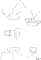
2 in mehreren Ansichten einen Umlenkspiegel der Spiegelvorrichtung, -
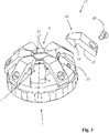
3 in einer perspektivischen Darstellung das Ausführungsbeispiel der Spiegelvorrichtung, -
4 in einer Schnittdarstellung ein Ausführungsbeispiel einer erfindungsgemäßen optischen Vorrichtung mit einem Mikroskopobjektiv und einer daran befestigten Spiegelvorrichtung mit sechs Umlenkspiegeln, -
5 das Ausführungsbeispiel der optischen Vorrichtung in einer ersten Seitendarstellung, -
6 das Ausführungsbeispiel der optischen Vorrichtung in einer zweiten Seitendarstellung, -
7 das Ausführungsbeispiel der optischen Vorrichtung in einer perspektivischen Darstellung, -
8 in einer ersten Seitendarstellung ein weiteres Ausführungsbeispiel einer erfindungsgemäßen optischen Vorrichtung mit einem Mikroskopobjektiv und einer daran befestigten Spiegelvorrichtung mit zwei Umlenkspiegeln, -
9 das weitere Ausführungsbeispiel der optischen Vorrichtung in einer zweiten Seitendarstellung, -
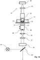
10 ein Ausführungsbeispiel eines erfindungsgemäßen Mikroskops.
-
1 in several side views and a perspective illustration, the holding component of an embodiment of a mirror device according to the invention, -
2 in several views a deflecting mirror of the mirror device, -
3 in a perspective view the embodiment of the mirror device, -
4th in a sectional view an embodiment of an optical device according to the invention with a microscope objective and a mirror device with six deflecting mirrors attached to it, -
5 the embodiment of the optical device in a first side view, -
6th the embodiment of the optical device in a second side view, -
7th the embodiment of the optical device in a perspective view, -
8th In a first side view, a further embodiment of an optical device according to the invention with a microscope objective and a mirror device with two deflecting mirrors attached to it, -
9 the further embodiment of the optical device in a second side view, -
10 an embodiment of a microscope according to the invention.
Das Haltebauteil
Das Haltebauteil
Jede Aufnahme
Die Strahlablenkvorrichtung
Vorzugsweise ist das Beleuchtungslichtblatt
Das von der mit dem Beleuchtungslichtblatt
Beispielsweise kann auf diese Weise zunächst eine erste Abbildung der Probe
Das Mikroskop weist eine weitere Lichtquelle
Hierbei ist zu berücksichtigen, dass die Foki von Beleuchtungslicht und Manipulationslicht unterschiedliche Positionen innerhalb der Probe
Dies wird durch Verschieben des Objektivs
BezugszeichenlisteList of reference symbols
- 11
- HaltebauteilRetaining component
- 22
- VerbindungselementConnecting element
- 33
- Innengewindeinner thread
- 44th
- AufnahmenRecordings
- 55
- BefestigungsgewindeFastening thread
- 66th
- erster Durchgangfirst try
- 77th
- zweiter Durchgangsecond pass
- 88th
- UntersuchungspositionExamination position
- 99
- TransportwegTransport route
- 1010
- UmlenkspiegelDeflection mirror
- 1212th
- erster Anschlagfirst stop
- 1313th
- zweiter Anschlagsecond stop
- 1414th
- erste Gegenanschlagflächefirst counter stop surface
- 1515th
- zweite Gegenanschlagflächesecond counter stop surface
- 1616
- BefestigungsdurchgangFastening passage
- 1717th
- SpiegelvorrichtungMirror device
- 1818th
- MikroskopobjektivMicroscope objective
- 1919th
- AußengewindeExternal thread
- 2020th
- Schraubescrew
- 2121
- SpiegeloberflächeMirror surface
- 2222nd
- Probesample
- 2323
- BeleuchtungslichtblattIlluminating light sheet
- 2424
- LichtquelleLight source
- 2525th
- StrahlteilerBeam splitter
- 2626th
- StrahlablenkvorrichtungBeam deflector
- 2727
- ScanlinseScanning lens
- 2828
- TubuslinseTube lens
- 2929
- EintrittspupilleEntrance pupil
- 3030th
- Objektivlens
- 3131
- DetektionsvorrichtungDetection device
- 3232
- DetektionsobjektivDetection lens
- 3333
- Optikoptics
- 3434
- Detektordetector
Claims (20)
Priority Applications (5)
| Application Number | Priority Date | Filing Date | Title |
|---|---|---|---|
| DE102015114756.4A DE102015114756B4 (en) | 2014-09-25 | 2015-09-03 | Mirror device |
| US15/513,087 US10768399B2 (en) | 2014-09-25 | 2015-09-25 | Mirror device |
| CN201580051949.7A CN107076963B (en) | 2014-09-25 | 2015-09-25 | Mirror device |
| PCT/EP2015/072144 WO2016046384A1 (en) | 2014-09-25 | 2015-09-25 | Mirror device |
| JP2017516460A JP6602855B2 (en) | 2014-09-25 | 2015-09-25 | Mirror device |
Applications Claiming Priority (3)
| Application Number | Priority Date | Filing Date | Title |
|---|---|---|---|
| DE102014113939.9 | 2014-09-25 | ||
| DE102014113939 | 2014-09-25 | ||
| DE102015114756.4A DE102015114756B4 (en) | 2014-09-25 | 2015-09-03 | Mirror device |
Publications (2)
| Publication Number | Publication Date |
|---|---|
| DE102015114756A1 DE102015114756A1 (en) | 2016-03-31 |
| DE102015114756B4 true DE102015114756B4 (en) | 2021-07-22 |
Family
ID=55485928
Family Applications (1)
| Application Number | Title | Priority Date | Filing Date |
|---|---|---|---|
| DE102015114756.4A Active DE102015114756B4 (en) | 2014-09-25 | 2015-09-03 | Mirror device |
Country Status (5)
| Country | Link |
|---|---|
| US (1) | US10768399B2 (en) |
| JP (1) | JP6602855B2 (en) |
| CN (1) | CN107076963B (en) |
| DE (1) | DE102015114756B4 (en) |
| WO (1) | WO2016046384A1 (en) |
Families Citing this family (2)
| Publication number | Priority date | Publication date | Assignee | Title |
|---|---|---|---|---|
| DE102013213781A1 (en) * | 2013-03-20 | 2014-09-25 | Leica Microsystems Cms Gmbh | Method and optical arrangement for manipulating and imaging a microscopic sample |
| DE102017107733B4 (en) | 2017-04-10 | 2019-01-31 | Leica Microsystems Cms Gmbh | Light sheet microscope and retrofit kit for this |
Citations (5)
| Publication number | Priority date | Publication date | Assignee | Title |
|---|---|---|---|---|
| DE10257423A1 (en) | 2002-12-09 | 2004-06-24 | Europäisches Laboratorium für Molekularbiologie (EMBL) | Microscope used in molecular biology comprises a focussing arrangement producing an extended planar object illumination region, a detection device, and a movement arrangement |
| DE102004034957A1 (en) | 2004-07-16 | 2006-02-02 | Carl Zeiss Jena Gmbh | Arrangement for microscopic observation and / or detection and use |
| DE202011110077U1 (en) | 2011-10-28 | 2012-11-29 | Leica Microsystems Cms Gmbh | Arrangement for illuminating a sample |
| DE102011054914A1 (en) | 2011-10-28 | 2013-05-02 | Leica Microsystems Cms Gmbh | Method and arrangement for illuminating a sample |
| DE102012214568A1 (en) | 2012-08-16 | 2014-02-20 | Leica Microsystems Cms Gmbh | Optical arrangement and a microscope |
Family Cites Families (27)
| Publication number | Priority date | Publication date | Assignee | Title |
|---|---|---|---|---|
| US2741153A (en) | 1951-09-18 | 1956-04-10 | Kapella Ltd | Optical projection systems |
| JPS5719647A (en) * | 1980-07-11 | 1982-02-01 | Hitachi Ltd | Inspecting device for sample of face plate |
| JPS6044014U (en) * | 1983-09-03 | 1985-03-28 | 網本 均 | Screw and spring adjustment focusing mirror |
| DE3427592A1 (en) * | 1984-07-26 | 1986-02-06 | Fa. Carl Zeiss, 7920 Heidenheim | Coaxial illuminating system for surgical microscopes |
| US4714327A (en) * | 1986-03-14 | 1987-12-22 | Westinghouse Electric Corp. | Oblique observation attachment for microscopes |
| US5253106A (en) * | 1992-03-20 | 1993-10-12 | Amarel Precision Instruments, Inc. | Oblique viewing system for microscopes |
| JPH0894812A (en) * | 1994-09-21 | 1996-04-12 | Sumitomo Electric Ind Ltd | Segment mirror and manufacturing method thereof |
| JP3797704B2 (en) * | 1996-04-05 | 2006-07-19 | 株式会社ミツトヨ | Optical measuring device |
| WO1998034094A1 (en) * | 1997-01-31 | 1998-08-06 | The Horticulture & Food Research Institute Of New Zealand Ltd. | Optical apparatus |
| US6179439B1 (en) * | 1998-06-10 | 2001-01-30 | Optical Gaging Products, Inc. | High-incidence programmable surface illuminator for video inspection systems |
| US6853448B2 (en) * | 2002-06-14 | 2005-02-08 | Karl J. Lenz | Multi-directional mirror device and method for optical inspection and autofocus measurement of objects |
| JP4216028B2 (en) * | 2002-09-20 | 2009-01-28 | 富士通株式会社 | Mirror fixing method and optical device |
| DE10320529B4 (en) * | 2003-04-30 | 2017-09-07 | Carl Zeiss Microscopy Gmbh | Dark field illumination system |
| JP2004361589A (en) * | 2003-06-03 | 2004-12-24 | Matsushita Electric Ind Co Ltd | Mirror adjustment mechanism and mirror adjustment holding method |
| US7234824B2 (en) * | 2003-09-22 | 2007-06-26 | Langley Nicholas M | Glare-elimination device for surgical microscopes |
| JP4532930B2 (en) * | 2004-02-20 | 2010-08-25 | オリンパス株式会社 | Dark field illumination device |
| JP2005321509A (en) * | 2004-05-07 | 2005-11-17 | Olympus Corp | Optical element |
| JP4687248B2 (en) | 2005-05-31 | 2011-05-25 | Nok株式会社 | Appearance inspection device |
| JP2007017699A (en) | 2005-07-07 | 2007-01-25 | Olympus Corp | Objective lens and mounting method thereof |
| JP2010127897A (en) * | 2008-12-01 | 2010-06-10 | Tech Vision:Kk | Ring type lighting system |
| DE102009028149B4 (en) * | 2009-07-31 | 2011-12-08 | Leica Instruments (Singapore) Pte. Ltd. | Illumination device for a microscope |
| US20130170024A1 (en) * | 2010-09-14 | 2013-07-04 | Applied Precision, Inc. | Oblique-illumination systems and methods |
| WO2012053241A1 (en) * | 2010-10-22 | 2012-04-26 | 株式会社ニコン | Microscope apparatus |
| DE102011051949B4 (en) | 2011-07-19 | 2017-05-18 | Leica Microsystems Cms Gmbh | Changing device for a microscope |
| DE102012211943A1 (en) * | 2012-07-09 | 2014-06-12 | Carl Zeiss Microscopy Gmbh | microscope |
| DE102013213781A1 (en) * | 2013-03-20 | 2014-09-25 | Leica Microsystems Cms Gmbh | Method and optical arrangement for manipulating and imaging a microscopic sample |
| DE102013211426A1 (en) * | 2013-06-18 | 2014-12-18 | Leica Microsystems Cms Gmbh | Method and optical device for microscopically examining a plurality of samples |
-
2015
- 2015-09-03 DE DE102015114756.4A patent/DE102015114756B4/en active Active
- 2015-09-25 WO PCT/EP2015/072144 patent/WO2016046384A1/en not_active Ceased
- 2015-09-25 CN CN201580051949.7A patent/CN107076963B/en active Active
- 2015-09-25 JP JP2017516460A patent/JP6602855B2/en active Active
- 2015-09-25 US US15/513,087 patent/US10768399B2/en active Active
Patent Citations (5)
| Publication number | Priority date | Publication date | Assignee | Title |
|---|---|---|---|---|
| DE10257423A1 (en) | 2002-12-09 | 2004-06-24 | Europäisches Laboratorium für Molekularbiologie (EMBL) | Microscope used in molecular biology comprises a focussing arrangement producing an extended planar object illumination region, a detection device, and a movement arrangement |
| DE102004034957A1 (en) | 2004-07-16 | 2006-02-02 | Carl Zeiss Jena Gmbh | Arrangement for microscopic observation and / or detection and use |
| DE202011110077U1 (en) | 2011-10-28 | 2012-11-29 | Leica Microsystems Cms Gmbh | Arrangement for illuminating a sample |
| DE102011054914A1 (en) | 2011-10-28 | 2013-05-02 | Leica Microsystems Cms Gmbh | Method and arrangement for illuminating a sample |
| DE102012214568A1 (en) | 2012-08-16 | 2014-02-20 | Leica Microsystems Cms Gmbh | Optical arrangement and a microscope |
Non-Patent Citations (1)
| Title |
|---|
| Journal of modern optics, 1999, vol. 46, no. 5, 843-858 beschrieben |
Also Published As
| Publication number | Publication date |
|---|---|
| DE102015114756A1 (en) | 2016-03-31 |
| CN107076963B (en) | 2020-03-06 |
| CN107076963A (en) | 2017-08-18 |
| US10768399B2 (en) | 2020-09-08 |
| US20170293131A1 (en) | 2017-10-12 |
| JP2017530408A (en) | 2017-10-12 |
| WO2016046384A1 (en) | 2016-03-31 |
| JP6602855B2 (en) | 2019-11-06 |
Similar Documents
| Publication | Publication Date | Title |
|---|---|---|
| EP2976669B1 (en) | Method and optical arrangement for manipulating and imaging a microscopic sample | |
| EP2587295B1 (en) | Method and device for illuminating a sample | |
| EP3532885B1 (en) | Optical arrangement, multi-spot scanning microscope and method for operating a microscope | |
| DE102012017917B4 (en) | Microscope module and light microscope as well as methods and data storage media | |
| WO2014063764A1 (en) | Microscope with at least one illuminating beam in the form of a light sheet | |
| WO2014009080A1 (en) | Microscope | |
| DE102017122718A1 (en) | Method and apparatus for optically examining a plurality of microscopic samples | |
| EP1423746A2 (en) | Microscope | |
| DE10356826B4 (en) | Scanning microscope | |
| EP3044567B1 (en) | Cuvette for an inverted fluorescence analysis | |
| DE202011110077U1 (en) | Arrangement for illuminating a sample | |
| DE102013211426A1 (en) | Method and optical device for microscopically examining a plurality of samples | |
| DE10115589A1 (en) | Arrangement for investigating microscopic preparations, has optical component between scanning laser and imaging optical arrangement to spectrally expand laser light during single pass | |
| EP2977810A1 (en) | Method and device for microscopically examining a sample | |
| EP1664888A1 (en) | Scanning microscope with evanescent wave illumination | |
| DE102014110575B4 (en) | Microscope and method for optically examining and / or manipulating a microscopic sample | |
| EP1141761A1 (en) | System for introducing optical tweezers and/or a treatment beam into a microscope | |
| EP1946173B1 (en) | Sample manipulation device | |
| DE102015114756B4 (en) | Mirror device | |
| DE102014118025B4 (en) | Light sheet microscopy device | |
| WO2016166374A1 (en) | Method and device for the spim analysis of a sample | |
| DE102017116892B4 (en) | Light source module for generating a light sheet plane, microscope and method for the sequential examination of several samples by means of a light sheet plane microscope | |
| EP3341781B1 (en) | Illumination arrangement for a light sheet microscope | |
| DE102014110341A1 (en) | Method and apparatus for microscopically examining a sample | |
| EP1407308A2 (en) | Microscope lens and the use of a microscope lens of this type in a microscope |
Legal Events
| Date | Code | Title | Description |
|---|---|---|---|
| R012 | Request for examination validly filed | ||
| R082 | Change of representative |
Representative=s name: DEHNS GERMANY PARTNERSCHAFT MBB, DE Representative=s name: KUDLEK GRUNERT & PARTNER PATENTANWAELTE MBB, DE Representative=s name: DEHNSGERMANY PARTNERSCHAFT VON PATENTANWAELTEN, DE |
|
| R016 | Response to examination communication | ||
| R018 | Grant decision by examination section/examining division | ||
| R082 | Change of representative |
Representative=s name: DEHNS GERMANY PARTNERSCHAFT MBB, DE Representative=s name: DEHNSGERMANY PARTNERSCHAFT VON PATENTANWAELTEN, DE |
|
| R020 | Patent grant now final |