EP3010813B1 - Device for extracting pills from a blister and method for adjusting the device - Google Patents
Device for extracting pills from a blister and method for adjusting the device Download PDFInfo
- Publication number
- EP3010813B1 EP3010813B1 EP14737337.7A EP14737337A EP3010813B1 EP 3010813 B1 EP3010813 B1 EP 3010813B1 EP 14737337 A EP14737337 A EP 14737337A EP 3010813 B1 EP3010813 B1 EP 3010813B1
- Authority
- EP
- European Patent Office
- Prior art keywords
- blister pack
- partitions
- cassette
- pills
- side boundary
- Prior art date
- Legal status (The legal status is an assumption and is not a legal conclusion. Google has not performed a legal analysis and makes no representation as to the accuracy of the status listed.)
- Active
Links
Images


Classifications
-
- B—PERFORMING OPERATIONS; TRANSPORTING
- B65—CONVEYING; PACKING; STORING; HANDLING THIN OR FILAMENTARY MATERIAL
- B65B—MACHINES, APPARATUS OR DEVICES FOR, OR METHODS OF, PACKAGING ARTICLES OR MATERIALS; UNPACKING
- B65B69/00—Unpacking of articles or materials, not otherwise provided for
- B65B69/005—Unpacking of articles or materials, not otherwise provided for by expelling contents, e.g. by squeezing the container
- B65B69/0058—Solid contents
-
- A—HUMAN NECESSITIES
- A61—MEDICAL OR VETERINARY SCIENCE; HYGIENE
- A61J—CONTAINERS SPECIALLY ADAPTED FOR MEDICAL OR PHARMACEUTICAL PURPOSES; DEVICES OR METHODS SPECIALLY ADAPTED FOR BRINGING PHARMACEUTICAL PRODUCTS INTO PARTICULAR PHYSICAL OR ADMINISTERING FORMS; DEVICES FOR ADMINISTERING FOOD OR MEDICINES ORALLY; BABY COMFORTERS; DEVICES FOR RECEIVING SPITTLE
- A61J1/00—Containers specially adapted for medical or pharmaceutical purposes
- A61J1/03—Containers specially adapted for medical or pharmaceutical purposes for pills or tablets
- A61J1/035—Blister-type containers
Definitions
- the invention relates to a device for extracting pills from a blister pack provided with a push-through foil according to the preamble of claim 1 and to a method for adjusting said device.
- the device according to the preamble of claim 1 is known in the field and is described in the international patent application WO 2013/072579 .
- the device is referred to in technical terms as a deblistering machine.
- the known device has a number of drawbacks.
- the drawback of the known device is that in the known device the push-through foil of the blister pack is not tensioned during pushing-through of the pills, whereby it occurs that one or more pills remain behind in the blister pack. Tensioning of the foil is for that matter an operation which a person often also performs when pressing a pill manually out of the blister pack.
- the known device has the drawback that, due to the form of the extracting surface, the blister pack is placed unstably in the device so that automatic feed of the blister packs is difficult. It is hereby difficult or impossible to automate the known device.
- the known device moreover has the drawback that not all pills pressed out of the blister pack drop directly into the collecting means but onto or alongside components of the known device. These are components which are difficult to access, whereby these components cannot be cleaned effectively. The pills can as a result become contaminated with substances from previous blister packs.
- the object of the invention to provide a device according to the preamble of claim 1 which wholly or largely obviates the above drawbacks.
- the device according to the invention has for this purpose the feature that the at least partially curved extracting surface takes a concave form. This measure ensures that the push-through foil is tensioned when the pills are pressed out, whereby the pills no longer remain behind in the blister pack. As a result of the measure taken the blister pack moreover remains lying in stable manner in the device.
- the one or more pressure rollers are arranged for rotation around a rotation shaft, wherein the longitudinal direction of each pressure roller runs parallel to the rotation shaft and the rotation shaft is arranged substantially above the extracting surface.
- the pressure roller is no longer limited to a reciprocating movement but can also make a rotating movement, whereby there are more possibilities for automating the device according to the invention.
- the extracting surface preferably takes an at least partially cylindrical form and the rotation shaft coincides with the axis of the cylindrically formed part of the extracting surface. Owing to these measures the pressure rollers will roll more easily over the extracting surface, wherein the pressure exerted by the pressure roller is substantially the same over all parts of the blister pack.
- the rolling pressure of at least one pressure roller is preferably adjustable. It is however most recommended to make the rolling pressure of all pressure rollers adjustable.
- the pressure rollers are disposed in pairs such that during operation each pair of pressure rollers rolls over a blister pack. Pressing out of the pills can hereby be performed in two steps, wherein the first pressure roller of the pair of pressure rollers breaks the push-through foil, preferably at a high rolling pressure, and the second pressure roller of the pair of pressure rollers presses the pills out of the blister pack. It is of course also possible here that the first pressure roller of the pair of pressure rollers will have pressed pills out of the blister pack.
- the device according to the invention is preferably provided with one or more sweeping means which are each arranged rotatably around the rotation shaft such that during operation one of the sweeping means sweeps over at least a part of the extracting surface after the pills have been pressed out of a placed blister pack by the one or more pressure rollers. With these measures an empty blister pack will be automatically removed from the extracting surface by the sweeping means. Once the pills have been pressed out of a blister pack the device is hereby ready for the following blister pack, and the blister pack does not first have to be removed manually.
- the extracting surface is preferably provided with a stop member for holding the blister pack in position during rolling of one of the pressure rollers over the blister pack during operation.
- the device is provided with one or more brushes and means for rotating the brushes, wherein the one or more brushes are arranged rotatably around the rotation shaft and the longitudinal direction of each brush runs parallel to the rotation shaft and wherein the brushes brush over at least a part of the blister pack during operation.
- the device is preferably provided with motors for rotating the brushes. The technical effect of these measures is that the blister pack is set into vibration, whereby the pills present in the blister pack are vibrated out of the blister pack.
- the partitions are substantially flat and run parallel, and the partitions are arranged such that the pills pressed through the blister pack can drop without interruption via the drop openings into the collecting means.
- an extracting surface is created on the upper side thereof which can be adapted to the type of blister pack. It is important here that the pills can drop unimpeded into the collecting means without being obstructed by components for arranging the partitions in the device.
- the preferred embodiment of the device is for this purpose preferably further provided with at least two first guides which run parallel and which each lie substantially transversely of the partitions and which are intended for the purpose of supporting the partitions and adjusting the mutual distance between the partitions.
- the first guides are mounted here such that the pills are not obstructed by the first guides when dropping into the collecting means.
- each first guide is preferably provided with a series of first grooves into which a partition can be locked.
- the first grooves of the first guides correspond to each other, wherein the mutual distance between the partitions can be adjusted discretely in a simple manner.
- the series of partitions is preferably arranged substantially transversely of the longitudinal direction of each of the pressure rollers, whereby the pressure rollers are supported over the whole extracting surface.
- the first partition in the series of partitions is preferably arranged such that, when the pressure roller rolls over the blister pack, the pressure roller does not make contact with the first partition and forms a first side boundary for the blister pack.
- the device is further provided with a second side boundary for the blister pack which is arranged on the device such that, when each of the pressure rollers rolls over the blister pack, the second side boundary is pressed aside by the relevant pressure roller.
- the device In order to automate the device, the device is provided with an automatic feed and discharge of blister packs.
- the device is preferably provided with a removable cassette in which the series of partitions, the at least two parallel first guides and the second side boundary are arranged.
- the device is preferably provided with a plurality of cassettes, each adapted to a different type of blister pack. It is hereby possible to make the device quickly suitable for a different type of blister pack by simply exchanging the cassette.
- the cassette is preferably provided with first locking means which are configured for co-action with placed partitions and the second side boundary and are intended for the purpose of locking the partitions and the second side boundary in the cassette. This prevents the setting of the partitions and the second side boundary becoming inaccurate.
- the device comprises a separate template in which a cassette taken out of the device can be received and wherein the template comprises two bearing surfaces mounted on either side of the template and intended for placing and adjustment of the partitions and the second side boundary in the first guides, wherein each bearing surface is provided with a first edge such that, following placing of the cassette in the template, the first edge lies in line with the first side boundary and each bearing surface is provided with a second edge which during operation lies at right angles to the partitions, and which second edge is provided with a series of second grooves lying in line with the series of first grooves.
- the device is provided with second locking means configured for co-action with the cassette and intended for the purpose of locking the cassette in the device.
- At least one pressure roller is removable from the device and provided with one or more pressure rings which are each arranged round a periphery of a pressure roller and wherein the position of each pressure ring is such that during operation of the device the pressure ring makes contact with an upper side of the blister pack under which at least one pill is located.
- the invention also relates to a method for adjusting a cassette in the device, said method having the features of claim 15. The invention will be discussed in more detail hereinbelow with reference to the following figures, in which:
- Figure 1 shows a cross-sectional view of the preferred embodiment of device 1 according to the invention provided with automatic blister pack feed means 2 and an automatic discharge 3 for pills.
- the automatic blister pack feed means 2 comprise a conveyor belt 7 and a blister pack supply holder 8.
- the automatic blister pack feed means 2 are configured such that a blister pack 5 is deposited from blister pack supply holder 8 onto conveyor belt 7, after which conveyor belt 7 transports blister pack 5 further.
- Deblistering machine 1 is provided with an at least partially curved extracting surface 6 which takes a concave form and onto which the blister pack 5 is deposited by the automatic blister pack feed means 2.
- the push-through foil lies here against extracting surface 6.
- Extracting surface 6 is provided on the underside thereof with drop openings corresponding to positions of pills 4 in blister pack 5. The drop openings are more readily visible in the other figures.
- Deblistering machine 1 also comprises four rotatable pressure rollers 7A, 7B, 7C, 7D which are preferably each provided with a rubber layer.
- Pressure rollers 7A, 7B, 7C, 7D are arranged rotatably around a rotation shaft 8, this rotation shaft lying perpendicularly of the plane of Figure 1 .
- the longitudinal direction of each pressure roller 7A, 7B, 7C, 7D runs parallel here to rotation shaft 8 and also lies perpendicularly of the plane of Figure 1 . It is important that rotation shaft 8 is arranged above extracting surface 6.
- Pressure rollers 7A, 7B, 7C, 7D are disposed in pairs such that during operation each pair of pressure rollers 7A, 7B; 7C, 7D rolls over one blister pack.
- Pressure rollers 7A, 7B, 7C, 7D are each mounted on a rotating plate 9 which is arranged rotatably about rotation shaft 8. Each of the pressure rollers 7A, 7B, 7C, 7D can rotate here about its own pressure roller shaft 10A, 10B, 10C and 10D.
- the rolling pressure at which each pressure roller 7A, 7B, 7C, 7D is rollable during operation over at least a part of the surface of blister pack 5 is adjustable by means of spring device 11A, 11B, 11C, 11D.
- Collecting means 12 can be a container, but also a conveyor belt.
- Collecting means 12 is shown in figure 1 as a conveyor belt which transports the pills further to a conveyor belt 13 and conveyor belt 14. Because conveyor belt 13 has a higher rotational speed than conveyor belt 12 and conveyor belt 14 has a higher rotational speed than conveyor belt 13, the pills 4 are singulated.
- Device 1 can hereby be provided with a counting mechanism which counts the pills at the end of conveyor belt 14 before pills 4 drop into a container 15.
- Extracting surface 6 takes a partially cylindrical form, wherein rotation shaft 8 coincides with the axis of the cylindrically formed portion of extracting surface 6.
- Pressure rollers 7A, 7B, 7C, 7D can hereby roll better over extracting surface 6.
- Each pair of pressure rollers 7A, 7B; 7C, 7D is provided with sweeping means 15A, 15B which are arranged fixedly on rotating plate 9. Sweeping means 15A, 15B are hereby rotatable around rotation shaft 8, whereby during operation of device 1 the sweeping means 15A, 15B sweep over at least a part of extracting surface 6. The sweeping takes place after the pills have been pressed out of a placed blister pack by one of the pairs of pressure rollers 7A, 7B; 7C, 7D, whereby blister pack 5 is swept off extracting surface 6.
- Device 1 operates with the following automated steps:
- Figure 2 is a 3-D side view of the preferred embodiment of device 1 according to the invention of Figure 1 . Extracting surface 6 and conveyor belts 7, 12, 13, 14 are (partially) guarded by side plate 25. The outer ends of first guides 18A, 18B and second guide 22 are arranged in side plate 25.
- a guide 25 Arranged on conveyor belt 7 is a guide 25 which can be adjusted with guide adjusting means 23. Guide 25 forms a side boundary for blister packs 5 so that blister packs 5 can be transported parallel to conveyor belt 7 to extracting surface 6.
- Figure 3 is a 3-D top view of the preferred embodiment of the device according to the invention close to pressure rollers 7A, 7B, 7C, 7D and gives a better view of how pressure rollers 7A, 7B, 7C, 7D roll over extracting surface 6.
- Device 1 is provided with a series of substantially flat partitions 16 which run parallel, wherein at least a portion of an upper side thereof forms the extracting surface 6.
- the mutual distance between partitions 6 is adjustable, wherein the drop openings 17 are formed by one or more spaces between partitions 16.
- Partitions 16 are supported by means of two first guides 18A, 18B which run parallel and which each lie substantially transversely of partitions 16.
- Both first guides 18A, 18B are provided with corresponding first grooves 19, wherein each first groove is at least as wide as the thickness of each of the partitions 16.
- the mutual distance between the partitions can hereby be changed in simple manner by placing each of the partitions in the correct first grooves 19 of first guides 18A, 18B.
- the first partition in the series of partitions 16 does not make contact with pressure rollers 7A, 7B, 7C, 7D and lies slightly higher than the other partitions 16.
- the first partition hereby forms a first side boundary 20 for blister pack 5.
- Device 1 is further provided with a second side boundary 21 for blister pack 5.
- Side boundary 21 is arranged displaceably and rotatably on one side thereof on a second guide 22 such that, when one of the pressure rollers 7A, 7B, 7C, 7D rolls over blister pack 5, the second side boundary 21 is pressed aside by the relevant pressure roller 7A, 7B, 7C, 7D.
- Side boundary 21 is provided for this purpose with a resilient mechanism 22, such as a torsion spring, which ensures that side boundary 21 re-places itself after one of the pairs of pressure rollers 7A, 7B; 7C, 7D has rolled over the extracting surface.
- Figure 4 is a 3-D side view of the preferred embodiment of device 1 according to the invention close to pressure rollers 7A, 7B, 7C, 7D wherein the assembly of partitions 16 in device 1 is made apparent.
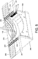
- FIG. 5 shows a removable cassette 100 for use in the device according to the invention.
- Removable cassette 100 is box-like and can be received in the device according to the invention.
- Cassette 100 comprises a series of partitions 117, a series of first grooves 119 (only one side visible) and at least two first guides 118 (only one side visible) which run parallel and are each provided with a series of first grooves 119 (only one side visible) and a first 120 and second side boundary 121.
- the operation and function of partitions 117, grooves 119, first guides 118 and first 120 and second side boundary 121 are the same as those of partitions 17, grooves 19, first guides 20 and first 20 and second side boundary 21 of the previous figures.
- the cassette is provided with first locking means which are configured for co-action with placed partitions 117 and the second side boundary 121 and which are intended for the purpose of locking the partitions 117 and the second side boundary 121 in cassette 100.
- first locking means which are configured for co-action with placed partitions 117 and the second side boundary 121 and which are intended for the purpose of locking the partitions 117 and the second side boundary 121 in cassette 100.
- the cassette 100 can be placed and received in a separate template 200.
- Template 200 comprises two bearing surfaces 201 mounted on either side of template 200 and intended for the purpose of placing and adjusting the partitions 117 and second side boundary 121 in first guides 118.
- Each bearing surface 201 is provided for this purpose with a first edge 102 which, after placing of cassette 100 in template 200, lies in line with first side boundary 120.
- Each bearing surface 201 is also provided with a second edge 203 which lies at right angles to partitions 117.
- Second edge 203 is provided with a series of second grooves 204 which lie in line with
- the method for adjusting a cassette 100 for a determined type of blister pack comprises the following steps of:
- Figure 6 shows a cassette 100 placed in device 1 according to the invention, wherein parts of device 1 have been omitted for the sake of clarity.
- cassette 100 is placed in device 1 under pressure rollers 10A, 10B, 10C.
- device 1 is embodied with four pressure rollers 10A, 10B, 10C, 10D. Later tests have shown that three pressure rollers are sufficient in the configuration of Figure 6 .
- Spring device 11A, 11B, 11C, 11D of Figure 1 can be omitted here, provided use is made of flexible pressure rings which are each arranged round a periphery of at least one pressure roller and wherein the position of each pressure ring is such that during operation of device 1 the pressure ring makes contact with a blister pack adjacently of a series of pills of the blister pack. It is essential here that the relevant pressure roller is removable from the device.
- Device 1 is provided with second locking means 30 which are configured for co-action with cassette 100 and intended for the purpose of locking the cassette 100 in device 1.
- Figure 7 shows the flexible pressure rings 300 which are arranged on at least one pressure roller 10A, 10B, 10C or 10D.
- Pressure rings 300 are each arranged round a periphery of a pressure roller.
- the position of each pressure ring 300 on pressure roller 10A, 10B, 10C or 10D is such that during operation of device 1 pressure ring 300 makes contact with an upper side of blister pack 5 under which at least one pill 4 is located.
- the number of pressure rings 300 is determined by the number of series of pills 4 on blister pack 5.
- the position of each pressure ring 300 preferably lies in the area D for each series of pills 4.
- the thickness and height of each pressure ring 300 is preferably adapted to the type of pill 4.
Landscapes
- Health & Medical Sciences (AREA)
- Engineering & Computer Science (AREA)
- Mechanical Engineering (AREA)
- Life Sciences & Earth Sciences (AREA)
- Animal Behavior & Ethology (AREA)
- General Health & Medical Sciences (AREA)
- Public Health (AREA)
- Veterinary Medicine (AREA)
- Pharmacology & Pharmacy (AREA)
- Control And Other Processes For Unpacking Of Materials (AREA)
- Medical Preparation Storing Or Oral Administration Devices (AREA)
- Auxiliary Devices For And Details Of Packaging Control (AREA)
Description
- The invention relates to a device for extracting pills from a blister pack provided with a push-through foil according to the preamble of
claim 1 and to a method for adjusting said device. The device according to the preamble ofclaim 1 is known in the field and is described in the international patent applicationWO 2013/072579 . The device is referred to in technical terms as a deblistering machine. - The known device has a number of drawbacks.
- The drawback of the known device is that in the known device the push-through foil of the blister pack is not tensioned during pushing-through of the pills, whereby it occurs that one or more pills remain behind in the blister pack. Tensioning of the foil is for that matter an operation which a person often also performs when pressing a pill manually out of the blister pack.
- In addition, the known device has the drawback that, due to the form of the extracting surface, the blister pack is placed unstably in the device so that automatic feed of the blister packs is difficult. It is hereby difficult or impossible to automate the known device.
- The known device moreover has the drawback that not all pills pressed out of the blister pack drop directly into the collecting means but onto or alongside components of the known device. These are components which are difficult to access, whereby these components cannot be cleaned effectively. The pills can as a result become contaminated with substances from previous blister packs.
- It is the object of the invention to provide a device according to the preamble of
claim 1 which wholly or largely obviates the above drawbacks. The device according to the invention has for this purpose the feature that the at least partially curved extracting surface takes a concave form. This measure ensures that the push-through foil is tensioned when the pills are pressed out, whereby the pills no longer remain behind in the blister pack. As a result of the measure taken the blister pack moreover remains lying in stable manner in the device. - In an embodiment of the device according to the invention which is highly suitable for automation the one or more pressure rollers are arranged for rotation around a rotation shaft, wherein the longitudinal direction of each pressure roller runs parallel to the rotation shaft and the rotation shaft is arranged substantially above the extracting surface. In contrast to the known device, the pressure roller is no longer limited to a reciprocating movement but can also make a rotating movement, whereby there are more possibilities for automating the device according to the invention.
- The extracting surface preferably takes an at least partially cylindrical form and the rotation shaft coincides with the axis of the cylindrically formed part of the extracting surface. Owing to these measures the pressure rollers will roll more easily over the extracting surface, wherein the pressure exerted by the pressure roller is substantially the same over all parts of the blister pack.
- The rolling pressure of at least one pressure roller is preferably adjustable. It is however most recommended to make the rolling pressure of all pressure rollers adjustable.
- In a first embodiment of the device according to the invention the pressure rollers are disposed in pairs such that during operation each pair of pressure rollers rolls over a blister pack. Pressing out of the pills can hereby be performed in two steps, wherein the first pressure roller of the pair of pressure rollers breaks the push-through foil, preferably at a high rolling pressure, and the second pressure roller of the pair of pressure rollers presses the pills out of the blister pack. It is of course also possible here that the first pressure roller of the pair of pressure rollers will have pressed pills out of the blister pack.
- The device according to the invention is preferably provided with one or more sweeping means which are each arranged rotatably around the rotation shaft such that during operation one of the sweeping means sweeps over at least a part of the extracting surface after the pills have been pressed out of a placed blister pack by the one or more pressure rollers. With these measures an empty blister pack will be automatically removed from the extracting surface by the sweeping means. Once the pills have been pressed out of a blister pack the device is hereby ready for the following blister pack, and the blister pack does not first have to be removed manually.
- The extracting surface is preferably provided with a stop member for holding the blister pack in position during rolling of one of the pressure rollers over the blister pack during operation.
- In an alternative embodiment of the device according to the invention the device is provided with one or more brushes and means for rotating the brushes, wherein the one or more brushes are arranged rotatably around the rotation shaft and the longitudinal direction of each brush runs parallel to the rotation shaft and wherein the brushes brush over at least a part of the blister pack during operation. The device is preferably provided with motors for rotating the brushes. The technical effect of these measures is that the blister pack is set into vibration, whereby the pills present in the blister pack are vibrated out of the blister pack.
- In the preferred embodiment of the device the partitions are substantially flat and run parallel, and the partitions are arranged such that the pills pressed through the blister pack can drop without interruption via the drop openings into the collecting means. Using the flat partitions an extracting surface is created on the upper side thereof which can be adapted to the type of blister pack. It is important here that the pills can drop unimpeded into the collecting means without being obstructed by components for arranging the partitions in the device.
- The preferred embodiment of the device is for this purpose preferably further provided with at least two first guides which run parallel and which each lie substantially transversely of the partitions and which are intended for the purpose of supporting the partitions and adjusting the mutual distance between the partitions. The first guides are mounted here such that the pills are not obstructed by the first guides when dropping into the collecting means.
- In order to adjust the mutual distance between the partitions each first guide is preferably provided with a series of first grooves into which a partition can be locked. In the mounted situation of the first grooves, the first grooves of the first guides correspond to each other, wherein the mutual distance between the partitions can be adjusted discretely in a simple manner.
- The series of partitions is preferably arranged substantially transversely of the longitudinal direction of each of the pressure rollers, whereby the pressure rollers are supported over the whole extracting surface.
- In the preferred embodiment of the device the first partition in the series of partitions is preferably arranged such that, when the pressure roller rolls over the blister pack, the pressure roller does not make contact with the first partition and forms a first side boundary for the blister pack.
- In the preferred embodiment of the device according to the invention the device is further provided with a second side boundary for the blister pack which is arranged on the device such that, when each of the pressure rollers rolls over the blister pack, the second side boundary is pressed aside by the relevant pressure roller.
- In order to automate the device, the device is provided with an automatic feed and discharge of blister packs.
- The device is preferably provided with a removable cassette in which the series of partitions, the at least two parallel first guides and the second side boundary are arranged. The device is preferably provided with a plurality of cassettes, each adapted to a different type of blister pack. It is hereby possible to make the device quickly suitable for a different type of blister pack by simply exchanging the cassette.
- In order to secure the setting of a cassette for a determined type of blister pack, the cassette is preferably provided with first locking means which are configured for co-action with placed partitions and the second side boundary and are intended for the purpose of locking the partitions and the second side boundary in the cassette. This prevents the setting of the partitions and the second side boundary becoming inaccurate.
- In order to facilitate adjustment of the cassette, the device comprises a separate template in which a cassette taken out of the device can be received and wherein the template comprises two bearing surfaces mounted on either side of the template and intended for placing and adjustment of the partitions and the second side boundary in the first guides, wherein each bearing surface is provided with a first edge such that, following placing of the cassette in the template, the first edge lies in line with the first side boundary and each bearing surface is provided with a second edge which during operation lies at right angles to the partitions, and which second edge is provided with a series of second grooves lying in line with the series of first grooves.
- In order to secure the cassette in the device, the device is provided with second locking means configured for co-action with the cassette and intended for the purpose of locking the cassette in the device.
- In order to improve pressing-out of the pills from the blister pack, at least one pressure roller is removable from the device and provided with one or more pressure rings which are each arranged round a periphery of a pressure roller and wherein the position of each pressure ring is such that during operation of the device the pressure ring makes contact with an upper side of the blister pack under which at least one pill is located. The invention also relates to a method for adjusting a cassette in the device, said method having the features of claim 15. The invention will be discussed in more detail hereinbelow with reference to the following figures, in which:
-
Figure 1 is a schematic cross-sectional view of the preferred embodiment of the device according to the invention provided with automatic blister pack feed means and an automatic discharge for empty blister packs and pills; -
Figure 2 is a 3-D side view of the preferred embodiment of the device according to the invention ofFigure 1 ; -
Figure 3 is a 3-D top view of the preferred embodiment of the device according to the invention close to the pressure rollers; -
Figure 4 is a 3-D side view of the preferred embodiment of the device according to the invention close to the pressure rollers; -
Figure 5 shows a removable cassette for use in the device according to the invention; -
Figure 6 shows a cassette placed in the device according to the invention; -
Figure 7 shows the flexible pressure rings arranged on at least one pressure roller. - Similar components are designated in the figure with the same numerals.
-
Figure 1 shows a cross-sectional view of the preferred embodiment ofdevice 1 according to the invention provided with automatic blister pack feed means 2 and an automatic discharge 3 for pills. The automatic blister pack feed means 2 comprise aconveyor belt 7 and a blisterpack supply holder 8. The automatic blister pack feed means 2 are configured such that ablister pack 5 is deposited from blisterpack supply holder 8 ontoconveyor belt 7, after whichconveyor belt 7 transportsblister pack 5 further. -
Deblistering machine 1 is provided with an at least partially curved extractingsurface 6 which takes a concave form and onto which theblister pack 5 is deposited by the automatic blister pack feed means 2. The push-through foil lies here against extractingsurface 6. Extractingsurface 6 is provided on the underside thereof with drop openings corresponding to positions ofpills 4 inblister pack 5. The drop openings are more readily visible in the other figures. -
Deblistering machine 1 also comprises fourrotatable pressure rollers Pressure rollers rotation shaft 8, this rotation shaft lying perpendicularly of the plane ofFigure 1 . The longitudinal direction of eachpressure roller rotation shaft 8 and also lies perpendicularly of the plane ofFigure 1 . It is important thatrotation shaft 8 is arranged above extractingsurface 6.Pressure rollers pressure rollers -
Pressure rollers rotating plate 9 which is arranged rotatably aboutrotation shaft 8. Each of thepressure rollers pressure roller shaft pressure roller blister pack 5 is adjustable by means ofspring device - The
pills 4 pressed out ofblister pack 5 drop through the drop openings into collecting means 12. Collecting means 12 can be a container, but also a conveyor belt. Collecting means 12 is shown infigure 1 as a conveyor belt which transports the pills further to aconveyor belt 13 andconveyor belt 14. Becauseconveyor belt 13 has a higher rotational speed thanconveyor belt 12 andconveyor belt 14 has a higher rotational speed thanconveyor belt 13, thepills 4 are singulated.Device 1 can hereby be provided with a counting mechanism which counts the pills at the end ofconveyor belt 14 beforepills 4 drop into a container 15. - Extracting
surface 6 takes a partially cylindrical form, whereinrotation shaft 8 coincides with the axis of the cylindrically formed portion of extractingsurface 6.Pressure rollers surface 6. - Each pair of
pressure rollers sweeping means plate 9. Sweeping means 15A, 15B are hereby rotatable aroundrotation shaft 8, whereby during operation ofdevice 1 thesweeping means surface 6. The sweeping takes place after the pills have been pressed out of a placed blister pack by one of the pairs ofpressure rollers blister pack 5 is swept off extractingsurface 6. -
Device 1 operates with the following automated steps: - a) A
blister pack 5 is deposited from blisterpack supply holder 8 ontoconveyor belt 7. - b) The conveyor belt transports the blister pack to extracting
surface 6 and deposits theblister pack 5 thereon.Pressure rollers blister pack 5. - c) Rotating
plate 9 is rotated such that one of the pressure roller pairs 7A, 7B; 7C, 7D rolls over theblister pack 5 lying on extractingsurface 6. - d) Rotating
plate 9 is then rotated such that one of thesweeping means blister pack 5 off extractingsurface 6. - e) The pills pressed out of
blister pack 5 drop throughdrop openings 17 ontoconveyor belt 12, after which the pills are singulated on thefurther conveyor belts - f) Step a) is then performed again.
-
Figure 2 is a 3-D side view of the preferred embodiment ofdevice 1 according to the invention ofFigure 1 . Extractingsurface 6 andconveyor belts side plate 25. The outer ends offirst guides second guide 22 are arranged inside plate 25. - Arranged on
conveyor belt 7 is aguide 25 which can be adjusted with guide adjusting means 23.Guide 25 forms a side boundary forblister packs 5 so thatblister packs 5 can be transported parallel toconveyor belt 7 to extractingsurface 6. -
Figure 3 is a 3-D top view of the preferred embodiment of the device according to the invention close topressure rollers pressure rollers surface 6. -
Device 1 is provided with a series of substantiallyflat partitions 16 which run parallel, wherein at least a portion of an upper side thereof forms the extractingsurface 6. The mutual distance betweenpartitions 6 is adjustable, wherein thedrop openings 17 are formed by one or more spaces betweenpartitions 16.Partitions 16 are supported by means of twofirst guides partitions 16. Bothfirst guides first grooves 19, wherein each first groove is at least as wide as the thickness of each of thepartitions 16. The mutual distance between the partitions can hereby be changed in simple manner by placing each of the partitions in the correctfirst grooves 19 offirst guides guides pills 4 pressed out ofblister pack 5 can drop without interruption viadrop openings 20 ontoconveyor belt 12 without making contact with further components ofdevice 1. - When one of the
pressure rollers blister pack 5, the first partition in the series ofpartitions 16 does not make contact withpressure rollers other partitions 16. The first partition hereby forms afirst side boundary 20 forblister pack 5. -
Device 1 is further provided with asecond side boundary 21 forblister pack 5.Side boundary 21 is arranged displaceably and rotatably on one side thereof on asecond guide 22 such that, when one of thepressure rollers blister pack 5, thesecond side boundary 21 is pressed aside by therelevant pressure roller Side boundary 21 is provided for this purpose with aresilient mechanism 22, such as a torsion spring, which ensures thatside boundary 21 re-places itself after one of the pairs ofpressure rollers -
Figure 4 is a 3-D side view of the preferred embodiment ofdevice 1 according to the invention close topressure rollers partitions 16 indevice 1 is made apparent. -
Figure 5 shows aremovable cassette 100 for use in the device according to the invention.Removable cassette 100 is box-like and can be received in the device according to the invention.Cassette 100 comprises a series ofpartitions 117, a series of first grooves 119 (only one side visible) and at least two first guides 118 (only one side visible) which run parallel and are each provided with a series of first grooves 119 (only one side visible) and a first 120 andsecond side boundary 121. The operation and function ofpartitions 117,grooves 119,first guides 118 and first 120 andsecond side boundary 121 are the same as those ofpartitions 17,grooves 19, first guides 20 and first 20 andsecond side boundary 21 of the previous figures. The cassette is provided with first locking means which are configured for co-action with placedpartitions 117 and thesecond side boundary 121 and which are intended for the purpose of locking thepartitions 117 and thesecond side boundary 121 incassette 100. For the purpose of adjusting thecassette 100 for a determined type of blister pack, thecassette 100 can be placed and received in aseparate template 200.Template 200 comprises two bearingsurfaces 201 mounted on either side oftemplate 200 and intended for the purpose of placing and adjusting thepartitions 117 andsecond side boundary 121 in first guides 118. Each bearingsurface 201 is provided for this purpose with a first edge 102 which, after placing ofcassette 100 intemplate 200, lies in line withfirst side boundary 120. Each bearingsurface 201 is also provided with asecond edge 203 which lies at right angles topartitions 117.Second edge 203 is provided with a series ofsecond grooves 204 which lie in line with the series offirst grooves 119 onfirst guides 118. - The method for adjusting a
cassette 100 for a determined type of blister pack comprises the following steps of: - a) placing
cassette 100 intemplate 200. In order to facilitate placing ofcassette 100 intemplate 200, pins are preferably arranged on the template which correspond to holes incassette 100; - b) placing a blister pack of the determined type on each of the bearing surfaces 201;
- c) placing an elongate aligning
member 205 along a first series of pills in each of the blister packs, wherein the aligning member is placed in corresponding second grooves of the parallel second edge; - d) placing a
partition 117 in corresponding first grooves of the parallelfirst guides 118 along aligningmember 205; - e) repeating steps c) and d) for each following series of pills;
- f) placing a blister pack of the determined type on the
partitions 117 placed in step d) such that a first long side of the blister pack lies againstfirst side boundary 120; - g) placing
second side boundary 121 into correspondingfirst grooves 119 of the parallelfirst guides 118 such that a second long side of the blister pack lies againstsecond side boundary 121; - h) locking the placed partitions and the second side boundary to the cassette using the first locking means;
- i) taking
cassette 100 out oftemplate 200. -
Figure 6 shows acassette 100 placed indevice 1 according to the invention, wherein parts ofdevice 1 have been omitted for the sake of clarity. Oncecassette 100 has been set for a determined type of blister pack using the template according toFigure 5 ,cassette 100 is placed indevice 1 underpressure rollers previous figures device 1 is embodied with fourpressure rollers Figure 6 .Spring device Figure 1 can be omitted here, provided use is made of flexible pressure rings which are each arranged round a periphery of at least one pressure roller and wherein the position of each pressure ring is such that during operation ofdevice 1 the pressure ring makes contact with a blister pack adjacently of a series of pills of the blister pack. It is essential here that the relevant pressure roller is removable from the device. -
Device 1 is provided with second locking means 30 which are configured for co-action withcassette 100 and intended for the purpose of locking thecassette 100 indevice 1. -
Figure 7 shows the flexible pressure rings 300 which are arranged on at least onepressure roller pressure ring 300 onpressure roller device 1pressure ring 300 makes contact with an upper side ofblister pack 5 under which at least onepill 4 is located. The number of pressure rings 300 is determined by the number of series ofpills 4 onblister pack 5. The position of eachpressure ring 300 preferably lies in the area D for each series ofpills 4. The thickness and height of eachpressure ring 300 is preferably adapted to the type ofpill 4.
Claims (15)
- Device (1) for extracting pills (4) from a blister pack (5) provided with a push-through foil, comprising:- an at least partially curved extracting surface (6) for stationary placing of the blister pack (5), wherein the push-through foil lies against the extracting surface (6) and wherein the extracting surface (6) is formed by at least a portion of an upper side of a series of partitions (16) and drop openings (17) are formed by one or more spaces between the partitions (16) wherein the distance between partitions (16) is adjustable to correspond to the positions of the pills (4) in the blister pack (5),- one or more rotatable pressure rollers (7A;7B;7C;7D), wherein each pressure roller (7A;7B;7C;7D) is rollable with predetermined rolling pressure over at least a part of the surface of the blister pack (5) during operation for the purpose of pressing the pills (4) out of the blister pack (5) through the push-through foil and through the drop openings (17), and- a collecting means (12) placed under the extracting surface (6) for collecting pills (4) which have dropped through the drop openings (17),characterized in that
the at least partially curved extracting surface (6) takes a concave form. - Device (1) as claimed in claim 1, wherein the one or more pressure rollers (7A;7B;7C;7D) are arranged for rotation around a rotation shaft (8), wherein the longitudinal direction of each pressure roller (7A;7B;7C;7D) runs parallel to the rotation shaft (8) and the rotation shaft (8) is arranged substantially above the extracting surface (6).
- Device (1) as claimed in claim 2, wherein the extracting surface (6) takes an at least partially cylindrical form and wherein the rotation shaft (8) coincides with the axis of the cylindrically formed part of the extracting surface (6).
- Device (1) as claimed in any of the foregoing claims, wherein the partitions (16) are substantially flat and run parallel, and the partitions (16) are arranged such that the pills (4) pressed through the blister pack (5) can drop without interruption via the drop openings (17) into the collecting means (12).
- Device (1) as claimed in claim 4, wherein the device (1) is further provided with at least two first guides (18A;18B) which run parallel and which each lie substantially transversely of the partitions (16) and which are intended for the purpose of supporting the partitions (16) and adjusting the mutual distance between the partitions (16).
- Device (1) as claimed in claim 5, wherein each guide (18A;18B) is provided with a series of first grooves (19) intended for the purpose of adjusting the mutual distance between the partitions (16).
- Device (1) as claimed in claim 4, 5 or 6, wherein the series of partitions (16) is arranged substantially transversely of the longitudinal direction of each of the pressure rollers (7A;7B;7C;7D).
- Device (1) as claimed in claim 4, 5, 6 or 7, wherein the first partition in the series of partitions (16) is arranged such that, when the pressure roller (7A;7B;7C;7D) rolls over the blister pack (5), the pressure roller (7A;7B;7C;7D) does not make contact with the first partition and forms a first side boundary (20) for the blister pack (5).
- Device (1) as claimed in claim 8, wherein the device (1) is further provided with a second side boundary (21) for the blister pack (5) which is arranged on the device (1) such that, when one of the pressure rollers (7A;7B;7C;7D) rolls over the blister pack (5), the second side boundary (21) is pressed aside by the relevant pressure roller (7A;7B;7C;7D).
- Device (1) as claimed in any of the claims 4 to 9, wherein the device (1) is provided with a removable cassette (100) in which the series of partitions (117), the series of first grooves (119) and the at least two parallel first guides (118A;118B) and the second side boundary (121) are arranged.
- Device (1) as claimed in claim 10, wherein the cassette (100) is provided with first locking means which are configured for co-action with placed partitions (117) and the second side boundary (121) and are intended for the purpose of locking the partitions (117) and the second side boundary (121) in the cassette (100).
- Device (1) as claimed in claim 10 or 11, wherein the device (1) is provided with second locking means configured for co-action with the cassette (100) and intended for the purpose of locking the cassette (100) in the device (1).
- Device (1) as claimed in claim 10, 11 or 12, comprising a separate template (200) in which a cassette (100) taken out of the device (1) can be received and wherein the template (200) comprises two bearing surfaces (201) mounted on either side of the template (200) and intended for placing and adjustment of the partitions (117) and the second side boundary (121) in the first guides (118A;118B), wherein each bearing surface (201) is provided with a first edge (102) such that, following placing of the cassette (100) in the template (200), the first edge (102) lies in line with the first side boundary (120), and each bearing surface (201) is provided with a second edge (203) which lies at right angles to the partitions (117), and which second edge (203) is provided with a series of second grooves (204) lying in line with the series of first grooves (119).
- Device (1) as claimed in any of the foregoing claims, wherein at least one pressure roller (10A;10B;10C;10D) is removable from the device (1) and provided with one or more flexible pressure rings (300) which are each arranged round a periphery of a pressure roller (10A;10B;10C;10D) and wherein the position of each pressure ring (300) on the pressure roller (10A;10B;10C;10D) is such that during operation of the device (1) the pressure ring (300) makes contact with an upper side of the blister pack (5) under which at least one pill (4) is located.
- Method for adjusting a cassette (100) for a determined type of blister pack (5) in a device (1) as claimed in claim 13 or 14, comprising the following steps of:a) placing the cassette (100) in the template (200);b) placing a blister pack (5) of the determined type on each of the bearing surfaces (201);c) placing an elongate aligning member along a first series of pills (4) in each of the blister packs (5), wherein the aligning member is placed in corresponding first grooves (119) of the parallel first guides (118A;118B);d) placing a partition in corresponding first grooves (119) of the parallel first guides (118A;118B) along the aligning member;e) repeating steps c) and d) for each following series of pills (4);f) placing a blister pack (5) of the determined type on the partitions (16) such that a first side of the blister pack (5) lies against the first side boundary (20);g) placing the second side boundary (121) in corresponding first grooves (119) of the parallel first guides (118A;118B) such that a second side of the blister pack (5) remote from the first side lies against the second side boundary (121);h) locking the placed partitions (117) and the second side boundary (121) to the cassette (100) using the first locking means;i) removing the cassette (100) from the template (200).
Applications Claiming Priority (2)
| Application Number | Priority Date | Filing Date | Title |
|---|---|---|---|
| NL2010987A NL2010987C2 (en) | 2013-06-17 | 2013-06-17 | DEVICE FOR EXTRACTING PILLS FROM A BLISTER. |
| PCT/NL2014/050397 WO2014204305A1 (en) | 2013-06-17 | 2014-06-17 | Device for extracting pills from a blister and method for adjusting the device |
Publications (2)
| Publication Number | Publication Date |
|---|---|
| EP3010813A1 EP3010813A1 (en) | 2016-04-27 |
| EP3010813B1 true EP3010813B1 (en) | 2018-02-14 |
Family
ID=51168315
Family Applications (1)
| Application Number | Title | Priority Date | Filing Date |
|---|---|---|---|
| EP14737337.7A Active EP3010813B1 (en) | 2013-06-17 | 2014-06-17 | Device for extracting pills from a blister and method for adjusting the device |
Country Status (8)
| Country | Link |
|---|---|
| US (1) | US10099810B2 (en) |
| EP (1) | EP3010813B1 (en) |
| JP (1) | JP6552486B2 (en) |
| CN (1) | CN105307945B (en) |
| AU (1) | AU2014281917B2 (en) |
| CA (1) | CA2915023A1 (en) |
| NL (1) | NL2010987C2 (en) |
| WO (1) | WO2014204305A1 (en) |
Families Citing this family (2)
| Publication number | Priority date | Publication date | Assignee | Title |
|---|---|---|---|---|
| JP5840171B2 (en) * | 2013-05-14 | 2016-01-06 | 中洲電機株式会社 | PTP sheet guide device and tablet take-out device |
| JP6056910B2 (en) * | 2014-08-27 | 2017-01-11 | キヤノンマーケティングジャパン株式会社 | Tablet extraction device and tablet extraction method |
Family Cites Families (15)
| Publication number | Priority date | Publication date | Assignee | Title |
|---|---|---|---|---|
| US2587289A (en) * | 1945-08-24 | 1952-02-26 | Harold H Cook | Threshing machine |
| US2589440A (en) * | 1946-08-21 | 1952-03-18 | Robert H Sharpe | Thresher with suction and blast fans mounted in housing |
| US5038968A (en) * | 1990-11-01 | 1991-08-13 | Albetski Donald N | Medication deblistering apparatus and method |
| US5368187A (en) * | 1993-01-19 | 1994-11-29 | Poncetta; Stanley | Method and apparatus for dispensing materials from blister packages |
| US6024247A (en) | 1997-01-10 | 2000-02-15 | Apotex Inc. | Deblistering machine |
| GB9718783D0 (en) * | 1997-09-05 | 1997-11-12 | Sepha Pharmaceutics Ltd | Deblistering machine |
| DE29907976U1 (en) * | 1999-05-05 | 1999-09-16 | RBP Bauer GmbH, 52156 Monschau | Device for removing pharmaceutical and other products from blister packs |
| US6474500B1 (en) * | 2000-05-12 | 2002-11-05 | Gary W. Clem, Inc. | Method and means for planting field seeds in rows with different varieties of seeds |
| JP4427683B2 (en) * | 2002-10-11 | 2010-03-10 | 中洲電機株式会社 | Tablet take-out device |
| US8157125B2 (en) | 2007-04-19 | 2012-04-17 | Mts Medication Technologies, Inc. | Systems and methods for removing medication from packaging |
| JP2010006382A (en) | 2008-06-24 | 2010-01-14 | Naigai Kisho Kk | Opening apparatus for press through pack sheet |
| GB0914743D0 (en) | 2009-08-24 | 2009-09-30 | Pakrasi Sanjeet | Automated universal medication dispenser |
| FR2982847B1 (en) * | 2011-11-17 | 2014-01-24 | Jacques Touren | MACHINE FOR EXTRACTING PILLS FROM A BLISTER |
| JP5596760B2 (en) | 2012-09-21 | 2014-09-24 | 株式会社エルクエスト | Tablet supply device and unpacking system |
| US20140241838A1 (en) * | 2013-02-28 | 2014-08-28 | Linda Beck | Apparatus and Methods for Removal of Pills from Packaging |
-
2013
- 2013-06-17 NL NL2010987A patent/NL2010987C2/en active
-
2014
- 2014-06-17 JP JP2016519473A patent/JP6552486B2/en active Active
- 2014-06-17 AU AU2014281917A patent/AU2014281917B2/en active Active
- 2014-06-17 EP EP14737337.7A patent/EP3010813B1/en active Active
- 2014-06-17 WO PCT/NL2014/050397 patent/WO2014204305A1/en not_active Ceased
- 2014-06-17 CA CA2915023A patent/CA2915023A1/en not_active Abandoned
- 2014-06-17 CN CN201480034421.4A patent/CN105307945B/en active Active
- 2014-06-17 US US14/896,240 patent/US10099810B2/en active Active
Also Published As
| Publication number | Publication date |
|---|---|
| WO2014204305A1 (en) | 2014-12-24 |
| CN105307945B (en) | 2018-01-16 |
| US10099810B2 (en) | 2018-10-16 |
| US20160137329A1 (en) | 2016-05-19 |
| EP3010813A1 (en) | 2016-04-27 |
| CA2915023A1 (en) | 2014-12-24 |
| JP2016521619A (en) | 2016-07-25 |
| NL2010987C2 (en) | 2014-12-18 |
| HK1217934A1 (en) | 2017-01-27 |
| AU2014281917B2 (en) | 2017-10-19 |
| JP6552486B2 (en) | 2019-07-31 |
| AU2014281917A1 (en) | 2015-12-17 |
| CN105307945A (en) | 2016-02-03 |
Similar Documents
| Publication | Publication Date | Title |
|---|---|---|
| US8887603B2 (en) | Tablet feeder | |
| EP2535035B1 (en) | Medicine dispenser and method of discharging medicine | |
| CN103004942B (en) | Shell and meat separation method for shellfish product | |
| EP3010813B1 (en) | Device for extracting pills from a blister and method for adjusting the device | |
| US20140241838A1 (en) | Apparatus and Methods for Removal of Pills from Packaging | |
| PL95720B1 (en) | DEVICE FOR CHANGING THE POSITION OF BOXES OF CIGARETTES SLIDING ALONG THE CHANNEL, ESPECIALLY THE PACKING MACHINE CHANNEL | |
| CN102770348A (en) | Powder removal device of medicine dispenser | |
| WO2012144915A1 (en) | Conveyor device and method for aligning rod -like elements and the use of the conveyor device | |
| KR102910532B1 (en) | Tofu packing device | |
| JP5052934B2 (en) | Sliced bread dividing and carrying device | |
| US5328323A (en) | Stack making machine | |
| KR101076727B1 (en) | Cutting apparatus for the instant kimchi of rotation type | |
| CN110900384B (en) | A non-equal thickness drum brake pad outer arc grinding production line with automatic feeding and discharging | |
| HK1217934B (en) | Device for extracting pills from a blister and method for adjusting the device | |
| US9215879B2 (en) | Apparatus for producing pillow-shaped hollow bodies | |
| CN211020831U (en) | Sugar rod anti-blocking conveying mechanism for lollipop machine | |
| JP2018140502A5 (en) | ||
| CN119976423B (en) | A capacitor core feeding device | |
| JP4812398B2 (en) | Pot-type seedling container sowing device and pot-type seedling container sowing method | |
| DK2743046T3 (en) | Serving device for bread slices | |
| JP2004195641A (en) | Raw tea leaf cutting device | |
| JPH05112336A (en) | Pillow type packaged body delivering device | |
| US502311A (en) | Labeling-machine | |
| KR20120002810A (en) | Straw Collector |
Legal Events
| Date | Code | Title | Description |
|---|---|---|---|
| PUAI | Public reference made under article 153(3) epc to a published international application that has entered the european phase |
Free format text: ORIGINAL CODE: 0009012 |
|
| 17P | Request for examination filed |
Effective date: 20160111 |
|
| AK | Designated contracting states |
Kind code of ref document: A1 Designated state(s): AL AT BE BG CH CY CZ DE DK EE ES FI FR GB GR HR HU IE IS IT LI LT LU LV MC MK MT NL NO PL PT RO RS SE SI SK SM TR |
|
| AX | Request for extension of the european patent |
Extension state: BA ME |
|
| DAX | Request for extension of the european patent (deleted) | ||
| STAA | Information on the status of an ep patent application or granted ep patent |
Free format text: STATUS: EXAMINATION IS IN PROGRESS |
|
| 17Q | First examination report despatched |
Effective date: 20170406 |
|
| GRAP | Despatch of communication of intention to grant a patent |
Free format text: ORIGINAL CODE: EPIDOSNIGR1 |
|
| STAA | Information on the status of an ep patent application or granted ep patent |
Free format text: STATUS: GRANT OF PATENT IS INTENDED |
|
| INTG | Intention to grant announced |
Effective date: 20170810 |
|
| GRAS | Grant fee paid |
Free format text: ORIGINAL CODE: EPIDOSNIGR3 |
|
| GRAA | (expected) grant |
Free format text: ORIGINAL CODE: 0009210 |
|
| STAA | Information on the status of an ep patent application or granted ep patent |
Free format text: STATUS: THE PATENT HAS BEEN GRANTED |
|
| AK | Designated contracting states |
Kind code of ref document: B1 Designated state(s): AL AT BE BG CH CY CZ DE DK EE ES FI FR GB GR HR HU IE IS IT LI LT LU LV MC MK MT NL NO PL PT RO RS SE SI SK SM TR |
|
| REG | Reference to a national code |
Ref country code: GB Ref legal event code: FG4D |
|
| REG | Reference to a national code |
Ref country code: CH Ref legal event code: EP |
|
| REG | Reference to a national code |
Ref country code: IE Ref legal event code: FG4D |
|
| REG | Reference to a national code |
Ref country code: DE Ref legal event code: R096 Ref document number: 602014020950 Country of ref document: DE Ref country code: AT Ref legal event code: REF Ref document number: 969690 Country of ref document: AT Kind code of ref document: T Effective date: 20180315 |
|
| REG | Reference to a national code |
Ref country code: CH Ref legal event code: NV Representative=s name: SCHNEIDER FELDMANN AG PATENT- UND MARKENANWAEL, CH |
|
| REG | Reference to a national code |
Ref country code: NL Ref legal event code: FP |
|
| REG | Reference to a national code |
Ref country code: FR Ref legal event code: PLFP Year of fee payment: 5 |
|
| REG | Reference to a national code |
Ref country code: AT Ref legal event code: MK05 Ref document number: 969690 Country of ref document: AT Kind code of ref document: T Effective date: 20180214 |
|
| PG25 | Lapsed in a contracting state [announced via postgrant information from national office to epo] |
Ref country code: LT Free format text: LAPSE BECAUSE OF FAILURE TO SUBMIT A TRANSLATION OF THE DESCRIPTION OR TO PAY THE FEE WITHIN THE PRESCRIBED TIME-LIMIT Effective date: 20180214 Ref country code: CY Free format text: LAPSE BECAUSE OF FAILURE TO SUBMIT A TRANSLATION OF THE DESCRIPTION OR TO PAY THE FEE WITHIN THE PRESCRIBED TIME-LIMIT Effective date: 20180214 Ref country code: HR Free format text: LAPSE BECAUSE OF FAILURE TO SUBMIT A TRANSLATION OF THE DESCRIPTION OR TO PAY THE FEE WITHIN THE PRESCRIBED TIME-LIMIT Effective date: 20180214 Ref country code: NO Free format text: LAPSE BECAUSE OF FAILURE TO SUBMIT A TRANSLATION OF THE DESCRIPTION OR TO PAY THE FEE WITHIN THE PRESCRIBED TIME-LIMIT Effective date: 20180514 Ref country code: ES Free format text: LAPSE BECAUSE OF FAILURE TO SUBMIT A TRANSLATION OF THE DESCRIPTION OR TO PAY THE FEE WITHIN THE PRESCRIBED TIME-LIMIT Effective date: 20180214 Ref country code: FI Free format text: LAPSE BECAUSE OF FAILURE TO SUBMIT A TRANSLATION OF THE DESCRIPTION OR TO PAY THE FEE WITHIN THE PRESCRIBED TIME-LIMIT Effective date: 20180214 |
|
| PG25 | Lapsed in a contracting state [announced via postgrant information from national office to epo] |
Ref country code: RS Free format text: LAPSE BECAUSE OF FAILURE TO SUBMIT A TRANSLATION OF THE DESCRIPTION OR TO PAY THE FEE WITHIN THE PRESCRIBED TIME-LIMIT Effective date: 20180214 Ref country code: AT Free format text: LAPSE BECAUSE OF FAILURE TO SUBMIT A TRANSLATION OF THE DESCRIPTION OR TO PAY THE FEE WITHIN THE PRESCRIBED TIME-LIMIT Effective date: 20180214 Ref country code: LV Free format text: LAPSE BECAUSE OF FAILURE TO SUBMIT A TRANSLATION OF THE DESCRIPTION OR TO PAY THE FEE WITHIN THE PRESCRIBED TIME-LIMIT Effective date: 20180214 Ref country code: SE Free format text: LAPSE BECAUSE OF FAILURE TO SUBMIT A TRANSLATION OF THE DESCRIPTION OR TO PAY THE FEE WITHIN THE PRESCRIBED TIME-LIMIT Effective date: 20180214 Ref country code: GR Free format text: LAPSE BECAUSE OF FAILURE TO SUBMIT A TRANSLATION OF THE DESCRIPTION OR TO PAY THE FEE WITHIN THE PRESCRIBED TIME-LIMIT Effective date: 20180515 Ref country code: BG Free format text: LAPSE BECAUSE OF FAILURE TO SUBMIT A TRANSLATION OF THE DESCRIPTION OR TO PAY THE FEE WITHIN THE PRESCRIBED TIME-LIMIT Effective date: 20180514 |
|
| PG25 | Lapsed in a contracting state [announced via postgrant information from national office to epo] |
Ref country code: AL Free format text: LAPSE BECAUSE OF FAILURE TO SUBMIT A TRANSLATION OF THE DESCRIPTION OR TO PAY THE FEE WITHIN THE PRESCRIBED TIME-LIMIT Effective date: 20180214 Ref country code: EE Free format text: LAPSE BECAUSE OF FAILURE TO SUBMIT A TRANSLATION OF THE DESCRIPTION OR TO PAY THE FEE WITHIN THE PRESCRIBED TIME-LIMIT Effective date: 20180214 Ref country code: IT Free format text: LAPSE BECAUSE OF FAILURE TO SUBMIT A TRANSLATION OF THE DESCRIPTION OR TO PAY THE FEE WITHIN THE PRESCRIBED TIME-LIMIT Effective date: 20180214 Ref country code: PL Free format text: LAPSE BECAUSE OF FAILURE TO SUBMIT A TRANSLATION OF THE DESCRIPTION OR TO PAY THE FEE WITHIN THE PRESCRIBED TIME-LIMIT Effective date: 20180214 Ref country code: RO Free format text: LAPSE BECAUSE OF FAILURE TO SUBMIT A TRANSLATION OF THE DESCRIPTION OR TO PAY THE FEE WITHIN THE PRESCRIBED TIME-LIMIT Effective date: 20180214 |
|
| REG | Reference to a national code |
Ref country code: DE Ref legal event code: R097 Ref document number: 602014020950 Country of ref document: DE |
|
| PG25 | Lapsed in a contracting state [announced via postgrant information from national office to epo] |
Ref country code: SK Free format text: LAPSE BECAUSE OF FAILURE TO SUBMIT A TRANSLATION OF THE DESCRIPTION OR TO PAY THE FEE WITHIN THE PRESCRIBED TIME-LIMIT Effective date: 20180214 Ref country code: SM Free format text: LAPSE BECAUSE OF FAILURE TO SUBMIT A TRANSLATION OF THE DESCRIPTION OR TO PAY THE FEE WITHIN THE PRESCRIBED TIME-LIMIT Effective date: 20180214 Ref country code: CZ Free format text: LAPSE BECAUSE OF FAILURE TO SUBMIT A TRANSLATION OF THE DESCRIPTION OR TO PAY THE FEE WITHIN THE PRESCRIBED TIME-LIMIT Effective date: 20180214 Ref country code: DK Free format text: LAPSE BECAUSE OF FAILURE TO SUBMIT A TRANSLATION OF THE DESCRIPTION OR TO PAY THE FEE WITHIN THE PRESCRIBED TIME-LIMIT Effective date: 20180214 |
|
| PLBE | No opposition filed within time limit |
Free format text: ORIGINAL CODE: 0009261 |
|
| STAA | Information on the status of an ep patent application or granted ep patent |
Free format text: STATUS: NO OPPOSITION FILED WITHIN TIME LIMIT |
|
| 26N | No opposition filed |
Effective date: 20181115 |
|
| PG25 | Lapsed in a contracting state [announced via postgrant information from national office to epo] |
Ref country code: SI Free format text: LAPSE BECAUSE OF FAILURE TO SUBMIT A TRANSLATION OF THE DESCRIPTION OR TO PAY THE FEE WITHIN THE PRESCRIBED TIME-LIMIT Effective date: 20180214 |
|
| PG25 | Lapsed in a contracting state [announced via postgrant information from national office to epo] |
Ref country code: MC Free format text: LAPSE BECAUSE OF FAILURE TO SUBMIT A TRANSLATION OF THE DESCRIPTION OR TO PAY THE FEE WITHIN THE PRESCRIBED TIME-LIMIT Effective date: 20180214 Ref country code: LU Free format text: LAPSE BECAUSE OF NON-PAYMENT OF DUE FEES Effective date: 20180617 |
|
| PG25 | Lapsed in a contracting state [announced via postgrant information from national office to epo] |
Ref country code: MT Free format text: LAPSE BECAUSE OF NON-PAYMENT OF DUE FEES Effective date: 20180617 |
|
| PG25 | Lapsed in a contracting state [announced via postgrant information from national office to epo] |
Ref country code: TR Free format text: LAPSE BECAUSE OF FAILURE TO SUBMIT A TRANSLATION OF THE DESCRIPTION OR TO PAY THE FEE WITHIN THE PRESCRIBED TIME-LIMIT Effective date: 20180214 |
|
| PG25 | Lapsed in a contracting state [announced via postgrant information from national office to epo] |
Ref country code: PT Free format text: LAPSE BECAUSE OF FAILURE TO SUBMIT A TRANSLATION OF THE DESCRIPTION OR TO PAY THE FEE WITHIN THE PRESCRIBED TIME-LIMIT Effective date: 20180214 |
|
| PG25 | Lapsed in a contracting state [announced via postgrant information from national office to epo] |
Ref country code: HU Free format text: LAPSE BECAUSE OF FAILURE TO SUBMIT A TRANSLATION OF THE DESCRIPTION OR TO PAY THE FEE WITHIN THE PRESCRIBED TIME-LIMIT; INVALID AB INITIO Effective date: 20140617 Ref country code: MK Free format text: LAPSE BECAUSE OF NON-PAYMENT OF DUE FEES Effective date: 20180214 |
|
| PG25 | Lapsed in a contracting state [announced via postgrant information from national office to epo] |
Ref country code: IS Free format text: LAPSE BECAUSE OF FAILURE TO SUBMIT A TRANSLATION OF THE DESCRIPTION OR TO PAY THE FEE WITHIN THE PRESCRIBED TIME-LIMIT Effective date: 20180614 |
|
| REG | Reference to a national code |
Ref country code: CH Ref legal event code: PFA Owner name: LANGEMAAT, WILLEM, NL Free format text: FORMER OWNER: LANGEMAAT, WILLEM, NL |
|
| REG | Reference to a national code |
Ref country code: DE Ref legal event code: R082 Ref document number: 602014020950 Country of ref document: DE Representative=s name: PATENTANWALTSKANZLEI VIEL UND WIESKE PARTGMBB, DE Ref country code: DE Ref legal event code: R081 Ref document number: 602014020950 Country of ref document: DE Owner name: LO&T BEHEER B.V., NL Free format text: FORMER OWNER: LANGEMAAT, WILLEM, EMMEN, NL |
|
| REG | Reference to a national code |
Ref country code: CH Ref legal event code: PUE Owner name: LO&T BEHEER B.V., NL Free format text: FORMER OWNER: LANGEMAAT, WILLEM, NL |
|
| REG | Reference to a national code |
Ref country code: NL Ref legal event code: PD Owner name: LO&T BEHEER B.V.; NL Free format text: DETAILS ASSIGNMENT: CHANGE OF OWNER(S), ASSIGNMENT; FORMER OWNER NAME: LANGEMAAT, WILLEM Effective date: 20201201 |
|
| REG | Reference to a national code |
Ref country code: GB Ref legal event code: 732E Free format text: REGISTERED BETWEEN 20210107 AND 20210113 Ref country code: BE Ref legal event code: PD Owner name: LO&T BEHEER B.V.; NL Free format text: DETAILS ASSIGNMENT: CHANGE OF OWNER(S), CESSION; FORMER OWNER NAME: LANGEMAAT, WILLEM Effective date: 20201202 |
|
| P01 | Opt-out of the competence of the unified patent court (upc) registered |
Effective date: 20230531 |
|
| PGFP | Annual fee paid to national office [announced via postgrant information from national office to epo] |
Ref country code: NL Payment date: 20250402 Year of fee payment: 12 |
|
| PGFP | Annual fee paid to national office [announced via postgrant information from national office to epo] |
Ref country code: DE Payment date: 20250402 Year of fee payment: 12 |
|
| PGFP | Annual fee paid to national office [announced via postgrant information from national office to epo] |
Ref country code: GB Payment date: 20250402 Year of fee payment: 12 |
|
| PGFP | Annual fee paid to national office [announced via postgrant information from national office to epo] |
Ref country code: BE Payment date: 20250402 Year of fee payment: 12 |
|
| PGFP | Annual fee paid to national office [announced via postgrant information from national office to epo] |
Ref country code: FR Payment date: 20250402 Year of fee payment: 12 |
|
| PGFP | Annual fee paid to national office [announced via postgrant information from national office to epo] |
Ref country code: IE Payment date: 20250402 Year of fee payment: 12 |
|
| PGFP | Annual fee paid to national office [announced via postgrant information from national office to epo] |
Ref country code: CH Payment date: 20250701 Year of fee payment: 12 |