EP3009923B1 - Capteur de pression discret et dispositif électronique - Google Patents
Capteur de pression discret et dispositif électronique Download PDFInfo
- Publication number
- EP3009923B1 EP3009923B1 EP14885854.1A EP14885854A EP3009923B1 EP 3009923 B1 EP3009923 B1 EP 3009923B1 EP 14885854 A EP14885854 A EP 14885854A EP 3009923 B1 EP3009923 B1 EP 3009923B1
- Authority
- EP
- European Patent Office
- Prior art keywords
- force
- board component
- sensing
- pressure sensor
- force concentration
- Prior art date
- Legal status (The legal status is an assumption and is not a legal conclusion. Google has not performed a legal analysis and makes no representation as to the accuracy of the status listed.)
- Active
Links
- 239000000853 adhesive Substances 0.000 claims description 15
- 230000001070 adhesive effect Effects 0.000 claims description 15
- 239000000758 substrate Substances 0.000 claims description 14
- 238000001514 detection method Methods 0.000 claims description 13
- 238000003825 pressing Methods 0.000 claims description 3
- 239000012141 concentrate Substances 0.000 claims 1
- 238000009434 installation Methods 0.000 description 6
- 239000000919 ceramic Substances 0.000 description 5
- 230000006870 function Effects 0.000 description 5
- 239000000463 material Substances 0.000 description 5
- 238000005516 engineering process Methods 0.000 description 4
- 238000012545 processing Methods 0.000 description 4
- 230000001419 dependent effect Effects 0.000 description 3
- VYPSYNLAJGMNEJ-UHFFFAOYSA-N Silicium dioxide Chemical compound O=[Si]=O VYPSYNLAJGMNEJ-UHFFFAOYSA-N 0.000 description 2
- 239000011248 coating agent Substances 0.000 description 2
- 238000000576 coating method Methods 0.000 description 2
- 238000013461 design Methods 0.000 description 2
- 229920006335 epoxy glue Polymers 0.000 description 2
- 239000006260 foam Substances 0.000 description 2
- 238000003475 lamination Methods 0.000 description 2
- 238000000034 method Methods 0.000 description 2
- 229920002635 polyurethane Polymers 0.000 description 2
- 239000004814 polyurethane Substances 0.000 description 2
- 239000000741 silica gel Substances 0.000 description 2
- 229910002027 silica gel Inorganic materials 0.000 description 2
- 230000001052 transient effect Effects 0.000 description 2
- 238000005452 bending Methods 0.000 description 1
- 238000005524 ceramic coating Methods 0.000 description 1
- 238000006243 chemical reaction Methods 0.000 description 1
- 239000002131 composite material Substances 0.000 description 1
- 230000007423 decrease Effects 0.000 description 1
- 238000011161 development Methods 0.000 description 1
- 230000018109 developmental process Effects 0.000 description 1
- 239000011521 glass Substances 0.000 description 1
- 238000004519 manufacturing process Methods 0.000 description 1
- 238000005259 measurement Methods 0.000 description 1
- 239000002184 metal Substances 0.000 description 1
- 239000004033 plastic Substances 0.000 description 1
- 229920003023 plastic Polymers 0.000 description 1
- 229920000642 polymer Polymers 0.000 description 1
- 238000003672 processing method Methods 0.000 description 1
- 229910001220 stainless steel Inorganic materials 0.000 description 1
- 239000010935 stainless steel Substances 0.000 description 1
- 239000012780 transparent material Substances 0.000 description 1
- 230000005641 tunneling Effects 0.000 description 1
Images


Classifications
-
- H—ELECTRICITY
- H03—ELECTRONIC CIRCUITRY
- H03K—PULSE TECHNIQUE
- H03K17/00—Electronic switching or gating, i.e. not by contact-making and –breaking
- H03K17/94—Electronic switching or gating, i.e. not by contact-making and –breaking characterised by the way in which the control signals are generated
- H03K17/96—Touch switches
- H03K17/9625—Touch switches using a force resistance transducer
-
- G—PHYSICS
- G01—MEASURING; TESTING
- G01L—MEASURING FORCE, STRESS, TORQUE, WORK, MECHANICAL POWER, MECHANICAL EFFICIENCY, OR FLUID PRESSURE
- G01L5/00—Apparatus for, or methods of, measuring force, work, mechanical power, or torque, specially adapted for specific purposes
-
- H—ELECTRICITY
- H03—ELECTRONIC CIRCUITRY
- H03K—PULSE TECHNIQUE
- H03K17/00—Electronic switching or gating, i.e. not by contact-making and –breaking
- H03K17/94—Electronic switching or gating, i.e. not by contact-making and –breaking characterised by the way in which the control signals are generated
- H03K17/96—Touch switches
- H03K17/964—Piezo-electric touch switches
-
- G—PHYSICS
- G06—COMPUTING; CALCULATING OR COUNTING
- G06F—ELECTRIC DIGITAL DATA PROCESSING
- G06F2203/00—Indexing scheme relating to G06F3/00 - G06F3/048
- G06F2203/041—Indexing scheme relating to G06F3/041 - G06F3/045
- G06F2203/04102—Flexible digitiser, i.e. constructional details for allowing the whole digitising part of a device to be flexed or rolled like a sheet of paper
Definitions
- the present invention relates to the field of pressure sensor technologies, and in particular, to a discrete pressure sensor and an electronic device including the discrete pressure sensor.
- pressure sensors are gradually applied in various fields.
- the pressure sensors mainly increase an amount of detected information, and provide a possibility for strength control.
- By means of pressure operations, switch actions, information encryption, and the like can be controlled effectively.
- the pressure sensors in the prior art are generally capacitive sensors, or piezoelectric ceramic sensors, or the like. All the pressure sensors in the prior art are sensors formed by using complex circuit design and structure design. For example, a capacitive sensor needs to strictly control a distance between each capacitive point and a front panel, and obtain pressure information through a change of the distance. Therefore, a pressure sensor needs to have very high processing precision and assembly precision for implementation.
- a piezoelectric ceramic sensor obtains a magnitude of pressure by exerting a transient impact on a piezoelectric ceramic and obtaining a transient voltage change. In manufacturing, the piezoelectric ceramic sensor requires unified consistent piezoelectric ceramic components, and needs to be installed in a designated structure by using a special installation method. This greatly increases the use cost of pressure sensors and reduces the use scope thereof, and hinders large-scale promotion of pressure sensors, causing limitations on the use of the pressure sensors.
- the US 2009/134966 A1 discloses a force sensing resistor, which includes a substrate having separated electrically conductive traces and another substrate having a resistive layer in which the substrates are subjected to a biasing force such that the substrates contact one another with the resistive layer electrically connecting the traces with a resistance inversely dependent on the biasing force.
- a force sensing resistor output which is a function of the resistance is measured. Whether a change in magnitude of the force sensing resistor output during a time interval is greater than a threshold is determined.
- a touch applied on the force sensing resistor is detected during the time interval if the change is greater than the threshold.
- the EP 0489344 A1 discloses a keyboard, which consists of a grid of individual keys, each associated with a force sensor whose electrical resistance decreases proportionally with a force applied to its surface. To identify an activated key, identification signals are injected onto the rows and the sought-after row is identified from the signals collected on the terminals. The sought-after column is determined similarly by injecting identification signals into the columns.
- US 2012/144932 A1 discloses a pre-loaded force sensing resistor.
- An objective of the present invention is to provide a discrete pressure sensor to solve the problem that a pressure sensor in the prior art has a high use cost and that it is difficult to promote the use thereof because very high processing precision and assembly precision are required for implementation and a special installation method is required before the pressure sensor can be used.
- the discrete pressure sensor In comparison with the prior art, in the discrete pressure sensor provided by the present invention, after pressure is applied in the hollowed area of the force centralization sensing board component, force is centralized to the force centralization position, conveyed to the pressure sensing chip in a centralized manner, and converted into control information to control the external electronic device through a circuit or the like of the electronic device.
- the discrete pressure sensor has a simple structure, and does not have a high requirement on assembly precision. In an actual application, the discrete pressure sensor may be directly bonded onto an inner side of a front panel of the electronic device, and a user may control the electronic device through the discrete pressure sensor by touching and pressing positions in the hollowed area corresponding to the front panel.
- the discrete pressure sensor has a low requirement on installation, and is applicable in a wide scope.
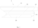
- FIG. 1 to FIG. 8 show exemplary embodiments provided by the present invention.
- a discrete pressure sensor 1 provided by an embodiment includes a force centralization sensing board component 12 and a pressure sensing chip 14, where the force centralization sensing board component 12 is bonded onto the pressure sensing chip 14, and the two are disposed in a lamination manner.
- the force centralization sensing board component 12 may be directly bonded onto an upper surface of the pressure sensing chip 14, or the two are bonded by using an adhesive or the like, which may be determined according to an actual requirement.
- the force centralization sensing board component 12 defines therein a hollowed area 122.
- the hollowed area 122 is located right above the pressure sensing chip 14.
- the hollowed area 122 has a force centralization position 1221.
- the force centralization position 1221 may centralize a force applied to a position of the force centralization sensing board component 12 corresponding to the hollowed area 122.
- the force centralization sensing board component 12 is bonded onto the upper surface of the pressure sensing chip 14, and thereby the force centralized in the force centralization position 1221 may be conveyed to the pressure sensing chip 14, and the pressure sensing chip 14 may sense the pressure applied in the corresponding hollowed area 122 and correspondingly convert the pressure into control information.
- the control information is transferred to an external control circuit or the like through a line or the like to further control corresponding operations of an electronic device or the like through the control circuit, for example, control a switch action and information encryption.
- the discrete pressure sensor 1 may be directly bonded onto an inner side of a front panel 10 of the electronic device, that is, the force centralization sensing board component 12 is bonded onto the inner side of the front panel 10.
- the force centralization sensing board component 12 is bonded onto the inner side of the front panel 10.
- keys or other positions for a marking pattern are disposed on the front panel 10 corresponding to the hollowed area on the force centralization sensing board component 12.
- the user may directly press the keys and the like on the front panel 10, and further, the pressure applied on the front panel 10 is conveyed to the hollowed area 122 of the force centralization sensing board component 12 and centralized in the force centralization position 1221 of the hollowed area 122, and by sensing the pressure in the force centralization position 1221, the pressure sensing chip 14 converts the pressure into control information and further controls the electronic device.
- the pressure sensor 1 uses the force centralization sensing board component 12 and the pressure sensing chip 14 that are disposed in a lamination manner, and does not require high processing precision and assembly precision for implementing pressure sensing. Its structure is simple. When it needs to be used, it may be directly bonded onto the inner side of the front panel 10 and used without special installation. Therefore, with low use cost, it may be used in various electronic devices having a front panel 10, and widely applicable.
- the force centralization sensing board component 12 and the pressure sensing chip 14 may be in a shape of a flat plate, or may be in a shape of a curved plate, or may be in other shapes of plates.
- the specific shape may be determined according to an actual requirement.
- the hollowed area 122 defined in the force centralization sensing board component 12 includes the force centralization position 1221 and bar-shaped external vacant positions 1222 formed by external extension of the force centralization position 1221.
- convex portions are located between adjacent bar-shaped external vacant positions 1222, the bar-shaped external vacant positions 1222 converge at the force centralization position 1221, and cantilever structures are formed by the convex portions between the adjacent bar-shaped external vacant positions 1222. Therefore, after pressure is applied on the hollowed area 122 of the force centralization sensing board component 12, the pressure is centralized to the force centralization position 1221 of the hollowed area 122.
- the force centralization position 1221 of the force centralization sensing board component 12 provided by this embodiment extends externally to form four bar-shaped external vacant positions 1222, and the end of each bar-shaped external vacant position 1222 extends towards two sides to form bar-shaped vacant positions 1223, and the bar-shaped vacant positions 1223 formed by the ends of the bar-shaped external vacant positions 1222 are closed to take on a shape of a broken square.
- an embodiment provides another force centralization sensing board component 12.
- a force centralization position in the force centralization sensing board component 12 extends externally to form six bar-shaped external vacant positions 1222, ends of the six bar-shaped external vacant positions 1222 form arc-shaped vacant positions 1224, and the six arc-shaped vacant positions 1224 are closed to take on a shape of a broken circle.
- a hollowed area 122 may also be in other shapes, so long as bar-shaped external vacant positions 1222 are formed by external extension of a force centralization position 1221.
- the shapes and paths of external extension of the bar-shaped external vacant positions 1222 may be diversified, and are not limited to the shapes in this embodiment.
- positions corresponding to the keys of the front panel 10 in the force centralization sensing board component 12 are divided into several portions, and in each portion, a short convex portion is reserved and connected to the force centralization sensing board component 12.
- a fixing structure is disposed at edges of the force centralization sensing board component 12, so that after the force centralization sensing board component 12 is disposed on the pressure sensing chip 14, its position may be fixed.
- the fixing structure includes fixing edge strips 121.
- the fixing edge strips 121 are disposed at the edges of the force centralization sensing board component 12, and bend downward, and take on a bending shape with the force centralization sensing board component 12. Therefore, the entire force centralization sensing board component 12 takes on a shape of a reversely worn cap.
- the fixing structure on the force centralization sensing board component 12 may be a plurality of other structures, for example, supporting ribs disposed at the edges of the force centralization sensing board component 12.
- the force centralization sensing board component 12 can also be substantially a planar board, that is, there is no protruding structure disposed at a periphery of the force centralization sensing board component 12.
- the pressure sensing chip includes a substrate and a sensing component disposed on the substrate.
- a pressure sensing chip14 is configured to implement a pressure sensing function.
- the pressure sensing chip 14 specifically includes a film substrate and a sensing component disposed on the film substrate.
- the film substrate may be made up of materials of PET, PC, PI, and the like.
- the sensing component on the substrate is disposed in alignment with the hollowed area 122 in the force centralization sensing board component 12.
- the sensing component is a coating or a line printed on a pressure sensing layer and capable of sensing pressure.
- the pressure sensing chip 14 may be a printed polymer coating that has pressure sensing performance, or may be a sintered piezoelectric ceramic coating, or the like, but is not limited thereto.
- the pressure sensing chip 14 may be a single independent pressure sensor, or may be any measurement apparatus capable of sensing pressure.
- the pressure sensing chip 14 may employ other technologies, for example, quantum tunneling composite, capacitive sensor, or other pressure sensing resistor technologies.
- the discrete pressure sensor 1 further includes a detection circuit 16.
- the pressure sensing chip 14 is connected to the detection circuit 16 by using a connecting line 15.
- the connecting line 15 is connected to the detection circuit 16.
- the connecting line 15 is merely used to describe a manner of connection between the pressure sensing chip 14 and the detection circuit 16, and in other embodiments, the pressure sensing chip 14 may also be electrically connected to the detection circuit 16 directly or indirectly in other manners.
- the detection circuit 16 may act as a control center.
- the detection circuit 16 receives control information transferred from the pressure sensing chip 14, and further controls the electronic device or the like.
- the detection circuit 16 is generally described as a combination of hardware and software having a plurality of processing methods.
- the hardware and software are configured to feed back the control information input by the pressure sensing chip 14, or communicate with a system associated with a customer, and execute additional related tasks or functions.
- the detection circuit 16 may be implemented as a general processor, a content addressable memory, a digital signal processor, a digital-to-analog conversion switch, a programmable logic device, a discrete hardware assembly, or other combinations.
- algorithm and software information related to a pressure touch screen or a pressure sensing system is embedded in the detection circuit 16.
- the hardware and software in the detection circuit 16 are configured to execute a plurality of functions, technologies, feedback, and processing tasks associated with the system of the customer.
- the force centralization sensing board component 12 and the pressure sensing chip 14 are directly bonded by using a first adhesive 11.
- the first adhesive 11 may be a double-sided adhesive, a VHB acrylic foam adhesive, an epoxy glue, a polyurethane adhesive, a silica gel, or other similar objects.
- the selection and thickness of these adhesive materials are decided according to materials of the force centralization sensing board component 12 and the pressure sensing chip 14.
- the pressure sensor 1 may be directly bonded onto the inner side of the front panel 10 of the electronic device, and a second adhesive 13 is disposed on the upper surface of the force centralization sensing board component 12.
- the second adhesive 13 may also be a double-sided adhesive, a VHB acrylic foam adhesive, an epoxy glue, a polyurethane adhesive, a silica gel, or other similar objects. In this manner, the user may directly bond the pressure sensor 1 onto the inner side of the front panel 10 of the electronic device by using the second adhesive 13 on the force centralization sensing board component 12.
- the discrete pressure sensor 1 further includes the front panel 10.
- the front panel 10 is bonded onto the upper surface of the force centralization sensing board component 12.
- the front panel 10 is a board component that has performance of flexibility and deformability. It is available for user operations, and maintains structural rigidity for the user. That the front panel 10 has performance of flexibility and deformability means that the front panel 10 is flexible and deformable, and capable of recovering to an original status, which includes maintaining electronic and structural functions of the front panel.
- the front panel 10 may be bent and deformed along a central axis; or the front panel 10 may be collapsed and formed along one point; or the front panel 10 has enough flexibility and deformability to adapt to the lower-layer force centralization sensing board component 12 and pressure sensing chip 14, that is, the front panel 10, the force centralization sensing board component 12, and the pressure sensing chip 14 are deformed synchronously, and a phenomenon of misalignment will not occur.
- the front panel 10 can maintain its rigid structure, because the front panel 10 itself will not be deformed and collapsed without external force.
- the front panel 10 may be made up of stainless steel, metal, glass, or plastic of a certain thickness; or the front panel 10 may be made up of a transparent material, and the thickness of the material is sufficient for maintaining flatness of the front panel 10.
- the front panel 10 may be made up of any material, so long as it has enough rigidity and has flexibility and deformability and can recover to the original status.
- a marking pattern is disposed on the outer surface of the front panel 10, and thereby, after the force centralization sensing board component 12 is bonded onto the front panel, the hollowed area 122 on the force centralization sensing board component 12 may be aligned with the marking pattern to identify preset press positions.
- An embodiment of the present invention further provides an electronic device, where the electronic device includes the discrete pressure sensor 1 provided above.
- the discrete pressure sensor 1 is bonded onto an inner side of a front panel of the electronic device, and thereby by means of touching and pressing a marking pattern such as keys on the surface of the front panel, pressure may be centralized by the force centralization sensing board component 12 and conveyed to a pressure sensing chip 14, and thereby the pressure is converted into control information to further control operations of the electronic device.
- the discrete pressure sensor 1 may be directly bonded onto the inner side of the front panel. It does not have a high requirement on installation precision. With a simple structure, the discrete pressure sensor 1 has advantages of low cost, ease of installation, and wide applicability.
Claims (9)
- Capteur de pression discret (1), comprenant un circuit de détection (16), une puce de captage de pression (14) et un composant de carte de captage de concentration de force (12) qui est collé sur la puce de captage de pression (14),le circuit de détection (16) étant relié électriquement à la puce de captage de pression (14) ;la puce de captage de pression (14) comprenant un substrat et un composant de captage placé sur le substrat, le composant de captage étant placé en alignement avec une région creuse (122) ;le composant de carte de captage de concentration de force (12) étant pourvu de la région creuse (122) et de structures en porte-à-faux, la région creuse (122) comprenant une position de concentration de force (1221) et une pluralité de parties évidées (1222) s'étendant vers la position de concentration de force (1221) à partir du composant de carte de captage de concentration de force (12), et une extrémité de chacune de la pluralité de parties évidées (1222) formant une intersection au niveau de la position de concentration de force (1221) ;les structures en porte-à-faux étant configurées pour concentrer une force de pression s'exerçant sur les structures en porte-à-faux du composant de carte de captage de force (12) vers la position de concentration de force (1221), et la position de concentration de force (1221) étant placée contre la puce de captage de pression (14),les structures en porte-à-faux étant formées par des parties du composant de carte de captage de concentration de force (12) qui sont définies par deux parties évidées (1222) adjacentes, une extrémité de chacune des parties étant fixée au composant de carte de captage de concentration de force (12).
- Capteur de pression discret (1) selon la revendication 1, dans lequel des bandes de bord de fixation (121) sont placées au niveau de bords du composant de carte de captage de concentration de force (12) .
- Capteur de pression discret (1) selon la revendication 1, dans lequel le composant de carte de captage de concentration de force (12) et la puce de captage de pression (14) sont collés au moyen d'un premier adhésif (11).
- Capteur de pression discret (1) selon la revendication 1, le capteur de pression discret (1) comprenant en outre un panneau avant (10), le panneau avant (10) étant collé sur le composant de carte de captage de concentration de force (12).
- Capteur de pression discret (1) selon la revendication 4, dans lequel le panneau avant (10) et le composant de carte de captage de concentration de force (12) sont collés au moyen d'un deuxième adhésif (13).
- Capteur de pression discret (1) selon la revendication 4, dans lequel le panneau avant (10) est un composant de carte présentant des qualités de souplesse et de déformabilité.
- Capteur de pression discret (1) selon la revendication 4, dans lequel un motif de marquage aligné avec la région creuse (122) dans le composant de carte de captage de concentration de force (12) est placé sur le panneau avant (10).
- Capteur de pression discret (1) selon la revendication 1, dans lequel le composant de carte de captage de concentration de force (12) est une carte plane.
- Dispositif électronique, comprenant le capteur de pression discret (1) selon l'une quelconque des revendications 1 à 8.
Applications Claiming Priority (1)
| Application Number | Priority Date | Filing Date | Title |
|---|---|---|---|
| PCT/CN2014/085168 WO2016029354A1 (fr) | 2014-08-26 | 2014-08-26 | Capteur de pression discret et dispositif électronique |
Publications (3)
| Publication Number | Publication Date |
|---|---|
| EP3009923A1 EP3009923A1 (fr) | 2016-04-20 |
| EP3009923A4 EP3009923A4 (fr) | 2017-03-01 |
| EP3009923B1 true EP3009923B1 (fr) | 2023-05-31 |
Family
ID=55398571
Family Applications (1)
| Application Number | Title | Priority Date | Filing Date |
|---|---|---|---|
| EP14885854.1A Active EP3009923B1 (fr) | 2014-08-26 | 2014-08-26 | Capteur de pression discret et dispositif électronique |
Country Status (5)
| Country | Link |
|---|---|
| US (1) | US9645023B2 (fr) |
| EP (1) | EP3009923B1 (fr) |
| JP (1) | JP6129424B2 (fr) |
| CN (1) | CN105518586B (fr) |
| WO (1) | WO2016029354A1 (fr) |
Families Citing this family (23)
| Publication number | Priority date | Publication date | Assignee | Title |
|---|---|---|---|---|
| WO2013165601A1 (fr) | 2012-05-03 | 2013-11-07 | Yknots Industries Llc | Capteur à poutres incurvées compensé en moment pour la mesure de charge sur une plateforme supportée par des poutres incurvées |
| WO2014098946A1 (fr) | 2012-12-17 | 2014-06-26 | Changello Enterprise Llc | Détection de force dans des dispositifs tactiles utilisant des capteurs piézoélectriques |
| US9952703B2 (en) | 2013-03-15 | 2018-04-24 | Apple Inc. | Force sensing of inputs through strain analysis |
| US10120478B2 (en) | 2013-10-28 | 2018-11-06 | Apple Inc. | Piezo based force sensing |
| AU2015100011B4 (en) | 2014-01-13 | 2015-07-16 | Apple Inc. | Temperature compensating transparent force sensor |
| US9612170B2 (en) | 2015-07-21 | 2017-04-04 | Apple Inc. | Transparent strain sensors in an electronic device |
| US10055048B2 (en) | 2015-07-31 | 2018-08-21 | Apple Inc. | Noise adaptive force touch |
| US9874965B2 (en) | 2015-09-11 | 2018-01-23 | Apple Inc. | Transparent strain sensors in an electronic device |
| US9886118B2 (en) | 2015-09-30 | 2018-02-06 | Apple Inc. | Transparent force sensitive structures in an electronic device |
| US10006820B2 (en) | 2016-03-08 | 2018-06-26 | Apple Inc. | Magnetic interference avoidance in resistive sensors |
| US10209830B2 (en) | 2016-03-31 | 2019-02-19 | Apple Inc. | Electronic device having direction-dependent strain elements |
| US10133418B2 (en) | 2016-09-07 | 2018-11-20 | Apple Inc. | Force sensing in an electronic device using a single layer of strain-sensitive structures |
| EP3379222B1 (fr) | 2017-03-22 | 2020-12-30 | Methode Electronics Malta Ltd. | Ensemble de capteur à base magnétoélastique |
| US10444091B2 (en) | 2017-04-11 | 2019-10-15 | Apple Inc. | Row column architecture for strain sensing |
| US10309846B2 (en) | 2017-07-24 | 2019-06-04 | Apple Inc. | Magnetic field cancellation for strain sensors |
| US11014417B2 (en) | 2018-02-27 | 2021-05-25 | Methode Electronics, Inc. | Towing systems and methods using magnetic field sensing |
| US11491832B2 (en) | 2018-02-27 | 2022-11-08 | Methode Electronics, Inc. | Towing systems and methods using magnetic field sensing |
| US11084342B2 (en) | 2018-02-27 | 2021-08-10 | Methode Electronics, Inc. | Towing systems and methods using magnetic field sensing |
| US11221262B2 (en) | 2018-02-27 | 2022-01-11 | Methode Electronics, Inc. | Towing systems and methods using magnetic field sensing |
| US10670479B2 (en) | 2018-02-27 | 2020-06-02 | Methode Electronics, Inc. | Towing systems and methods using magnetic field sensing |
| US11135882B2 (en) | 2018-02-27 | 2021-10-05 | Methode Electronics, Inc. | Towing systems and methods using magnetic field sensing |
| US10782818B2 (en) | 2018-08-29 | 2020-09-22 | Apple Inc. | Load cell array for detection of force input to an electronic device enclosure |
| KR20210020489A (ko) * | 2019-08-14 | 2021-02-24 | 삼성전자주식회사 | 개구부를 포함하는 전자장치 |
Family Cites Families (21)
| Publication number | Priority date | Publication date | Assignee | Title |
|---|---|---|---|---|
| US4166998A (en) * | 1977-06-22 | 1979-09-04 | Gould Inc., Statham Instrument Division | Force transducer |
| DE3232817C1 (de) * | 1982-09-03 | 1988-09-08 | Endress U. Hauser Gmbh U. Co, 7867 Maulburg | Biegefeder |
| US4994781A (en) * | 1988-04-07 | 1991-02-19 | Sahagen Armen N | Pressure sensing transducer employing piezoresistive elements on sapphire |
| EP0489344A1 (fr) * | 1990-12-03 | 1992-06-10 | I.E.E. International Electronics & Engineering S.à.r.l. | Procédé d'identification d'une touche activée d'un clavier à touches |
| JP3149544B2 (ja) * | 1992-06-22 | 2001-03-26 | 株式会社デンソー | 半導体圧力検出装置 |
| US5402666A (en) * | 1994-07-26 | 1995-04-04 | Scanivalve Corporation | Method and apparatus for precise measurement of differential pressures |
| US5600071A (en) * | 1995-09-05 | 1997-02-04 | Motorola, Inc. | Vertically integrated sensor structure and method |
| JP4295883B2 (ja) * | 1999-12-13 | 2009-07-15 | 株式会社ワコー | 力検出装置 |
| JP2004177343A (ja) * | 2002-11-28 | 2004-06-24 | Fujikura Ltd | 圧力センサ |
| EP2026178A1 (fr) * | 2007-08-10 | 2009-02-18 | IEE INTERNATIONAL ELECTRONICS & ENGINEERING S.A. | Pavé tactile à entrées en forme de bande |
| US7772960B2 (en) * | 2007-11-27 | 2010-08-10 | Interlink Electronics, Inc. | Pre-loaded force sensing resistor and method |
| JP5286153B2 (ja) * | 2009-04-28 | 2013-09-11 | アズビル株式会社 | 圧力センサの製造方法 |
| CN102375586B (zh) * | 2010-08-19 | 2014-12-03 | 苏州敏芯微电子技术有限公司 | 识别指向与力度的操纵系统 |
| JP2012122823A (ja) * | 2010-12-08 | 2012-06-28 | Seiko Epson Corp | 検出装置、電子機器、及びロボット |
| US8693200B2 (en) * | 2012-02-07 | 2014-04-08 | International Business Machines Corporation | Semiconductor device cooling module |
| US9684382B2 (en) | 2012-06-13 | 2017-06-20 | Microsoft Technology Licensing, Llc | Input device configuration having capacitive and pressure sensors |
| CN202887136U (zh) * | 2012-10-24 | 2013-04-17 | 深圳纽迪瑞科技开发有限公司 | 一种新型金属面板触摸屏 |
| CN202887103U (zh) * | 2012-10-30 | 2013-04-17 | 深圳纽迪瑞科技开发有限公司 | 一种新型超薄键盘 |
| US9222509B2 (en) * | 2013-09-11 | 2015-12-29 | Xdot Engineering And Analysis Pllc | Wing foil bearings and methods of manufacturing same |
| CN203721565U (zh) * | 2014-02-21 | 2014-07-16 | 博罗承创精密工业有限公司 | 按键用弹性触片 |
| CN103854903B (zh) * | 2014-02-21 | 2016-01-06 | 博罗承创精密工业有限公司 | 按键用弹性触片 |
-
2014
- 2014-08-26 US US14/779,820 patent/US9645023B2/en active Active
- 2014-08-26 WO PCT/CN2014/085168 patent/WO2016029354A1/fr active Application Filing
- 2014-08-26 CN CN201480004304.3A patent/CN105518586B/zh active Active
- 2014-08-26 JP JP2016544705A patent/JP6129424B2/ja active Active
- 2014-08-26 EP EP14885854.1A patent/EP3009923B1/fr active Active
Also Published As
| Publication number | Publication date |
|---|---|
| EP3009923A1 (fr) | 2016-04-20 |
| WO2016029354A1 (fr) | 2016-03-03 |
| US20160238474A1 (en) | 2016-08-18 |
| US9645023B2 (en) | 2017-05-09 |
| JP2016534372A (ja) | 2016-11-04 |
| EP3009923A4 (fr) | 2017-03-01 |
| CN105518586B (zh) | 2018-08-03 |
| CN105518586A (zh) | 2016-04-20 |
| JP6129424B2 (ja) | 2017-05-17 |
Similar Documents
| Publication | Publication Date | Title |
|---|---|---|
| EP3009923B1 (fr) | Capteur de pression discret et dispositif électronique | |
| JP6359143B2 (ja) | タッチスクリーンパネル用配線電極 | |
| KR102330585B1 (ko) | 터치 스크린 장치와 그의 구동 방법, 및 이를 포함하는 휴대용 전자 기기 | |
| EP2983067B1 (fr) | Dispositif d'entrée et appareil électronique | |
| TWI667595B (zh) | 輸入裝置、感測器、鍵盤及電子機器 | |
| JP6777068B2 (ja) | 入力装置および電気機器 | |
| KR101140954B1 (ko) | 투명 전도성 기판과 그 제조방법, 및 이를 이용한 터치스크린 | |
| US10198116B2 (en) | Pressure sensing device, pressure measuring apparatus, touch control board, and display apparatus | |
| JP6309055B2 (ja) | 抵抗膜式タッチパネルからのデータ取得方法、及び抵抗膜式タッチパネル装置 | |
| EP2323025A2 (fr) | Panneau tactile résistif à surface plane | |
| KR20110121662A (ko) | 터치패널 및 그 제조방법 | |
| EP3147947A1 (fr) | Dispositif à affichage électroluminescent organique et son procédé de fabrication | |
| KR101077433B1 (ko) | 터치스크린의 제조방법 | |
| US20150082897A1 (en) | Touch sensor module | |
| JP2012064211A (ja) | 静電容量方式タッチスクリーンの製造方法 | |
| US20170364161A1 (en) | Input device with key input and touch input, and operating method thereof | |
| CN208922223U (zh) | 一种触摸面板及显示装置 | |
| US20180107323A1 (en) | Display panel and display device | |
| US10275067B2 (en) | Pressure sensor, display apparatus and electronic device | |
| KR102070588B1 (ko) | 비전도성 물체로 터치입력이 가능한 스마트기기용 보호필름 | |
| WO2020129567A1 (fr) | Capteur sensible à la pression et instrument électronique | |
| KR102212879B1 (ko) | 터치 패널 | |
| KR20120038823A (ko) | 터치스크린 | |
| KR20110111333A (ko) | 터치스크린의 제조방법 | |
| TWM519275U (zh) | 功能玻璃罩蓋 |
Legal Events
| Date | Code | Title | Description |
|---|---|---|---|
| PUAI | Public reference made under article 153(3) epc to a published international application that has entered the european phase |
Free format text: ORIGINAL CODE: 0009012 |
|
| 17P | Request for examination filed |
Effective date: 20150924 |
|
| AK | Designated contracting states |
Kind code of ref document: A1 Designated state(s): AL AT BE BG CH CY CZ DE DK EE ES FI FR GB GR HR HU IE IS IT LI LT LU LV MC MK MT NL NO PL PT RO RS SE SI SK SM TR |
|
| AX | Request for extension of the european patent |
Extension state: BA ME |
|
| A4 | Supplementary search report drawn up and despatched |
Effective date: 20170126 |
|
| RIC1 | Information provided on ipc code assigned before grant |
Ipc: H03K 17/96 20060101AFI20170120BHEP |
|
| DAX | Request for extension of the european patent (deleted) | ||
| STAA | Information on the status of an ep patent application or granted ep patent |
Free format text: STATUS: EXAMINATION IS IN PROGRESS |
|
| 17Q | First examination report despatched |
Effective date: 20200228 |
|
| STAA | Information on the status of an ep patent application or granted ep patent |
Free format text: STATUS: EXAMINATION IS IN PROGRESS |
|
| STAA | Information on the status of an ep patent application or granted ep patent |
Free format text: STATUS: EXAMINATION IS IN PROGRESS |
|
| GRAP | Despatch of communication of intention to grant a patent |
Free format text: ORIGINAL CODE: EPIDOSNIGR1 |
|
| STAA | Information on the status of an ep patent application or granted ep patent |
Free format text: STATUS: GRANT OF PATENT IS INTENDED |
|
| INTG | Intention to grant announced |
Effective date: 20230220 |
|
| RIN1 | Information on inventor provided before grant (corrected) |
Inventor name: LI, HAO |
|
| GRAS | Grant fee paid |
Free format text: ORIGINAL CODE: EPIDOSNIGR3 |
|
| GRAA | (expected) grant |
Free format text: ORIGINAL CODE: 0009210 |
|
| STAA | Information on the status of an ep patent application or granted ep patent |
Free format text: STATUS: THE PATENT HAS BEEN GRANTED |
|
| AK | Designated contracting states |
Kind code of ref document: B1 Designated state(s): AL AT BE BG CH CY CZ DE DK EE ES FI FR GB GR HR HU IE IS IT LI LT LU LV MC MK MT NL NO PL PT RO RS SE SI SK SM TR |
|
| REG | Reference to a national code |
Ref country code: GB Ref legal event code: FG4D Ref country code: CH Ref legal event code: EP |
|
| REG | Reference to a national code |
Ref country code: AT Ref legal event code: REF Ref document number: 1571572 Country of ref document: AT Kind code of ref document: T Effective date: 20230615 Ref country code: DE Ref legal event code: R096 Ref document number: 602014087094 Country of ref document: DE |
|
| REG | Reference to a national code |
Ref country code: IE Ref legal event code: FG4D |
|
| REG | Reference to a national code |
Ref country code: LT Ref legal event code: MG9D |
|
| REG | Reference to a national code |
Ref country code: NL Ref legal event code: MP Effective date: 20230531 |
|
| REG | Reference to a national code |
Ref country code: AT Ref legal event code: MK05 Ref document number: 1571572 Country of ref document: AT Kind code of ref document: T Effective date: 20230531 |
|
| PG25 | Lapsed in a contracting state [announced via postgrant information from national office to epo] |
Ref country code: SE Free format text: LAPSE BECAUSE OF FAILURE TO SUBMIT A TRANSLATION OF THE DESCRIPTION OR TO PAY THE FEE WITHIN THE PRESCRIBED TIME-LIMIT Effective date: 20230531 Ref country code: NO Free format text: LAPSE BECAUSE OF FAILURE TO SUBMIT A TRANSLATION OF THE DESCRIPTION OR TO PAY THE FEE WITHIN THE PRESCRIBED TIME-LIMIT Effective date: 20230831 Ref country code: ES Free format text: LAPSE BECAUSE OF FAILURE TO SUBMIT A TRANSLATION OF THE DESCRIPTION OR TO PAY THE FEE WITHIN THE PRESCRIBED TIME-LIMIT Effective date: 20230531 Ref country code: AT Free format text: LAPSE BECAUSE OF FAILURE TO SUBMIT A TRANSLATION OF THE DESCRIPTION OR TO PAY THE FEE WITHIN THE PRESCRIBED TIME-LIMIT Effective date: 20230531 |
|
| PG25 | Lapsed in a contracting state [announced via postgrant information from national office to epo] |
Ref country code: RS Free format text: LAPSE BECAUSE OF FAILURE TO SUBMIT A TRANSLATION OF THE DESCRIPTION OR TO PAY THE FEE WITHIN THE PRESCRIBED TIME-LIMIT Effective date: 20230531 Ref country code: PL Free format text: LAPSE BECAUSE OF FAILURE TO SUBMIT A TRANSLATION OF THE DESCRIPTION OR TO PAY THE FEE WITHIN THE PRESCRIBED TIME-LIMIT Effective date: 20230531 Ref country code: NL Free format text: LAPSE BECAUSE OF FAILURE TO SUBMIT A TRANSLATION OF THE DESCRIPTION OR TO PAY THE FEE WITHIN THE PRESCRIBED TIME-LIMIT Effective date: 20230531 Ref country code: LV Free format text: LAPSE BECAUSE OF FAILURE TO SUBMIT A TRANSLATION OF THE DESCRIPTION OR TO PAY THE FEE WITHIN THE PRESCRIBED TIME-LIMIT Effective date: 20230531 Ref country code: LT Free format text: LAPSE BECAUSE OF FAILURE TO SUBMIT A TRANSLATION OF THE DESCRIPTION OR TO PAY THE FEE WITHIN THE PRESCRIBED TIME-LIMIT Effective date: 20230531 Ref country code: IS Free format text: LAPSE BECAUSE OF FAILURE TO SUBMIT A TRANSLATION OF THE DESCRIPTION OR TO PAY THE FEE WITHIN THE PRESCRIBED TIME-LIMIT Effective date: 20230930 Ref country code: HR Free format text: LAPSE BECAUSE OF FAILURE TO SUBMIT A TRANSLATION OF THE DESCRIPTION OR TO PAY THE FEE WITHIN THE PRESCRIBED TIME-LIMIT Effective date: 20230531 Ref country code: GR Free format text: LAPSE BECAUSE OF FAILURE TO SUBMIT A TRANSLATION OF THE DESCRIPTION OR TO PAY THE FEE WITHIN THE PRESCRIBED TIME-LIMIT Effective date: 20230901 |
|
| PG25 | Lapsed in a contracting state [announced via postgrant information from national office to epo] |
Ref country code: FI Free format text: LAPSE BECAUSE OF FAILURE TO SUBMIT A TRANSLATION OF THE DESCRIPTION OR TO PAY THE FEE WITHIN THE PRESCRIBED TIME-LIMIT Effective date: 20230531 |
|
| PG25 | Lapsed in a contracting state [announced via postgrant information from national office to epo] |
Ref country code: SK Free format text: LAPSE BECAUSE OF FAILURE TO SUBMIT A TRANSLATION OF THE DESCRIPTION OR TO PAY THE FEE WITHIN THE PRESCRIBED TIME-LIMIT Effective date: 20230531 |
|
| PG25 | Lapsed in a contracting state [announced via postgrant information from national office to epo] |
Ref country code: SM Free format text: LAPSE BECAUSE OF FAILURE TO SUBMIT A TRANSLATION OF THE DESCRIPTION OR TO PAY THE FEE WITHIN THE PRESCRIBED TIME-LIMIT Effective date: 20230531 Ref country code: SK Free format text: LAPSE BECAUSE OF FAILURE TO SUBMIT A TRANSLATION OF THE DESCRIPTION OR TO PAY THE FEE WITHIN THE PRESCRIBED TIME-LIMIT Effective date: 20230531 Ref country code: RO Free format text: LAPSE BECAUSE OF FAILURE TO SUBMIT A TRANSLATION OF THE DESCRIPTION OR TO PAY THE FEE WITHIN THE PRESCRIBED TIME-LIMIT Effective date: 20230531 Ref country code: PT Free format text: LAPSE BECAUSE OF FAILURE TO SUBMIT A TRANSLATION OF THE DESCRIPTION OR TO PAY THE FEE WITHIN THE PRESCRIBED TIME-LIMIT Effective date: 20231002 Ref country code: EE Free format text: LAPSE BECAUSE OF FAILURE TO SUBMIT A TRANSLATION OF THE DESCRIPTION OR TO PAY THE FEE WITHIN THE PRESCRIBED TIME-LIMIT Effective date: 20230531 Ref country code: DK Free format text: LAPSE BECAUSE OF FAILURE TO SUBMIT A TRANSLATION OF THE DESCRIPTION OR TO PAY THE FEE WITHIN THE PRESCRIBED TIME-LIMIT Effective date: 20230531 Ref country code: CZ Free format text: LAPSE BECAUSE OF FAILURE TO SUBMIT A TRANSLATION OF THE DESCRIPTION OR TO PAY THE FEE WITHIN THE PRESCRIBED TIME-LIMIT Effective date: 20230531 |
|
| REG | Reference to a national code |
Ref country code: DE Ref legal event code: R119 Ref document number: 602014087094 Country of ref document: DE |
|
| PG25 | Lapsed in a contracting state [announced via postgrant information from national office to epo] |
Ref country code: MC Free format text: LAPSE BECAUSE OF FAILURE TO SUBMIT A TRANSLATION OF THE DESCRIPTION OR TO PAY THE FEE WITHIN THE PRESCRIBED TIME-LIMIT Effective date: 20230531 |
|
| REG | Reference to a national code |
Ref country code: CH Ref legal event code: PL |
|
| PG25 | Lapsed in a contracting state [announced via postgrant information from national office to epo] |
Ref country code: MC Free format text: LAPSE BECAUSE OF FAILURE TO SUBMIT A TRANSLATION OF THE DESCRIPTION OR TO PAY THE FEE WITHIN THE PRESCRIBED TIME-LIMIT Effective date: 20230531 |
|
| PLBE | No opposition filed within time limit |
Free format text: ORIGINAL CODE: 0009261 |
|
| STAA | Information on the status of an ep patent application or granted ep patent |
Free format text: STATUS: NO OPPOSITION FILED WITHIN TIME LIMIT |
|
| PG25 | Lapsed in a contracting state [announced via postgrant information from national office to epo] |
Ref country code: LU Free format text: LAPSE BECAUSE OF NON-PAYMENT OF DUE FEES Effective date: 20230826 |
|
| GBPC | Gb: european patent ceased through non-payment of renewal fee |
Effective date: 20230831 |
|
| PG25 | Lapsed in a contracting state [announced via postgrant information from national office to epo] |
Ref country code: LU Free format text: LAPSE BECAUSE OF NON-PAYMENT OF DUE FEES Effective date: 20230826 Ref country code: CH Free format text: LAPSE BECAUSE OF NON-PAYMENT OF DUE FEES Effective date: 20230831 |
|
| PG25 | Lapsed in a contracting state [announced via postgrant information from national office to epo] |
Ref country code: SI Free format text: LAPSE BECAUSE OF FAILURE TO SUBMIT A TRANSLATION OF THE DESCRIPTION OR TO PAY THE FEE WITHIN THE PRESCRIBED TIME-LIMIT Effective date: 20230531 |
|
| 26N | No opposition filed |
Effective date: 20240301 |