EP3009663A1 - Valve assembly and fluid injector - Google Patents
Valve assembly and fluid injector Download PDFInfo
- Publication number
- EP3009663A1 EP3009663A1 EP14188946.9A EP14188946A EP3009663A1 EP 3009663 A1 EP3009663 A1 EP 3009663A1 EP 14188946 A EP14188946 A EP 14188946A EP 3009663 A1 EP3009663 A1 EP 3009663A1
- Authority
- EP
- European Patent Office
- Prior art keywords
- damping element
- armature
- valve
- assembly
- valve needle
- Prior art date
- Legal status (The legal status is an assumption and is not a legal conclusion. Google has not performed a legal analysis and makes no representation as to the accuracy of the status listed.)
- Granted
Links
- 239000012530 fluid Substances 0.000 title claims abstract description 59
- 238000013016 damping Methods 0.000 claims abstract description 133
- 230000000149 penetrating effect Effects 0.000 claims abstract description 17
- 238000002485 combustion reaction Methods 0.000 description 6
- 230000001052 transient effect Effects 0.000 description 5
- 229910000831 Steel Inorganic materials 0.000 description 2
- 230000001419 dependent effect Effects 0.000 description 2
- 230000000694 effects Effects 0.000 description 2
- 238000003754 machining Methods 0.000 description 2
- 238000000034 method Methods 0.000 description 2
- 239000010959 steel Substances 0.000 description 2
- 238000003466 welding Methods 0.000 description 2
- 230000004913 activation Effects 0.000 description 1
- 230000009286 beneficial effect Effects 0.000 description 1
- 230000002860 competitive effect Effects 0.000 description 1
- 239000000446 fuel Substances 0.000 description 1
- 230000003116 impacting effect Effects 0.000 description 1
- 238000002347 injection Methods 0.000 description 1
- 239000007924 injection Substances 0.000 description 1
- 238000004519 manufacturing process Methods 0.000 description 1
- 239000007787 solid Substances 0.000 description 1
- 125000006850 spacer group Chemical group 0.000 description 1
- 230000006641 stabilisation Effects 0.000 description 1
Images


Classifications
-
- F—MECHANICAL ENGINEERING; LIGHTING; HEATING; WEAPONS; BLASTING
- F02—COMBUSTION ENGINES; HOT-GAS OR COMBUSTION-PRODUCT ENGINE PLANTS
- F02M—SUPPLYING COMBUSTION ENGINES IN GENERAL WITH COMBUSTIBLE MIXTURES OR CONSTITUENTS THEREOF
- F02M51/00—Fuel-injection apparatus characterised by being operated electrically
- F02M51/06—Injectors peculiar thereto with means directly operating the valve needle
- F02M51/061—Injectors peculiar thereto with means directly operating the valve needle using electromagnetic operating means
- F02M51/0625—Injectors peculiar thereto with means directly operating the valve needle using electromagnetic operating means characterised by arrangement of mobile armatures
- F02M51/0664—Injectors peculiar thereto with means directly operating the valve needle using electromagnetic operating means characterised by arrangement of mobile armatures having a cylindrically or partly cylindrically shaped armature, e.g. entering the winding; having a plate-shaped or undulated armature entering the winding
- F02M51/0671—Injectors peculiar thereto with means directly operating the valve needle using electromagnetic operating means characterised by arrangement of mobile armatures having a cylindrically or partly cylindrically shaped armature, e.g. entering the winding; having a plate-shaped or undulated armature entering the winding the armature having an elongated valve body attached thereto
- F02M51/0682—Injectors peculiar thereto with means directly operating the valve needle using electromagnetic operating means characterised by arrangement of mobile armatures having a cylindrically or partly cylindrically shaped armature, e.g. entering the winding; having a plate-shaped or undulated armature entering the winding the armature having an elongated valve body attached thereto the body being hollow and its interior communicating with the fuel flow
-
- F—MECHANICAL ENGINEERING; LIGHTING; HEATING; WEAPONS; BLASTING
- F02—COMBUSTION ENGINES; HOT-GAS OR COMBUSTION-PRODUCT ENGINE PLANTS
- F02M—SUPPLYING COMBUSTION ENGINES IN GENERAL WITH COMBUSTIBLE MIXTURES OR CONSTITUENTS THEREOF
- F02M51/00—Fuel-injection apparatus characterised by being operated electrically
- F02M51/06—Injectors peculiar thereto with means directly operating the valve needle
- F02M51/061—Injectors peculiar thereto with means directly operating the valve needle using electromagnetic operating means
- F02M51/0625—Injectors peculiar thereto with means directly operating the valve needle using electromagnetic operating means characterised by arrangement of mobile armatures
- F02M51/0664—Injectors peculiar thereto with means directly operating the valve needle using electromagnetic operating means characterised by arrangement of mobile armatures having a cylindrically or partly cylindrically shaped armature, e.g. entering the winding; having a plate-shaped or undulated armature entering the winding
- F02M51/0685—Injectors peculiar thereto with means directly operating the valve needle using electromagnetic operating means characterised by arrangement of mobile armatures having a cylindrically or partly cylindrically shaped armature, e.g. entering the winding; having a plate-shaped or undulated armature entering the winding the armature and the valve being allowed to move relatively to each other or not being attached to each other
-
- F—MECHANICAL ENGINEERING; LIGHTING; HEATING; WEAPONS; BLASTING
- F02—COMBUSTION ENGINES; HOT-GAS OR COMBUSTION-PRODUCT ENGINE PLANTS
- F02M—SUPPLYING COMBUSTION ENGINES IN GENERAL WITH COMBUSTIBLE MIXTURES OR CONSTITUENTS THEREOF
- F02M51/00—Fuel-injection apparatus characterised by being operated electrically
- F02M51/06—Injectors peculiar thereto with means directly operating the valve needle
- F02M51/061—Injectors peculiar thereto with means directly operating the valve needle using electromagnetic operating means
- F02M51/0625—Injectors peculiar thereto with means directly operating the valve needle using electromagnetic operating means characterised by arrangement of mobile armatures
- F02M51/0664—Injectors peculiar thereto with means directly operating the valve needle using electromagnetic operating means characterised by arrangement of mobile armatures having a cylindrically or partly cylindrically shaped armature, e.g. entering the winding; having a plate-shaped or undulated armature entering the winding
- F02M51/0671—Injectors peculiar thereto with means directly operating the valve needle using electromagnetic operating means characterised by arrangement of mobile armatures having a cylindrically or partly cylindrically shaped armature, e.g. entering the winding; having a plate-shaped or undulated armature entering the winding the armature having an elongated valve body attached thereto
-
- F—MECHANICAL ENGINEERING; LIGHTING; HEATING; WEAPONS; BLASTING
- F02—COMBUSTION ENGINES; HOT-GAS OR COMBUSTION-PRODUCT ENGINE PLANTS
- F02M—SUPPLYING COMBUSTION ENGINES IN GENERAL WITH COMBUSTIBLE MIXTURES OR CONSTITUENTS THEREOF
- F02M61/00—Fuel-injectors not provided for in groups F02M39/00 - F02M57/00 or F02M67/00
- F02M61/16—Details not provided for in, or of interest apart from, the apparatus of groups F02M61/02 - F02M61/14
- F02M61/20—Closing valves mechanically, e.g. arrangements of springs or weights or permanent magnets; Damping of valve lift
-
- F—MECHANICAL ENGINEERING; LIGHTING; HEATING; WEAPONS; BLASTING
- F02—COMBUSTION ENGINES; HOT-GAS OR COMBUSTION-PRODUCT ENGINE PLANTS
- F02M—SUPPLYING COMBUSTION ENGINES IN GENERAL WITH COMBUSTIBLE MIXTURES OR CONSTITUENTS THEREOF
- F02M2200/00—Details of fuel-injection apparatus, not otherwise provided for
- F02M2200/30—Fuel-injection apparatus having mechanical parts, the movement of which is damped
- F02M2200/304—Fuel-injection apparatus having mechanical parts, the movement of which is damped using hydraulic means
-
- F—MECHANICAL ENGINEERING; LIGHTING; HEATING; WEAPONS; BLASTING
- F02—COMBUSTION ENGINES; HOT-GAS OR COMBUSTION-PRODUCT ENGINE PLANTS
- F02M—SUPPLYING COMBUSTION ENGINES IN GENERAL WITH COMBUSTIBLE MIXTURES OR CONSTITUENTS THEREOF
- F02M2200/00—Details of fuel-injection apparatus, not otherwise provided for
- F02M2200/30—Fuel-injection apparatus having mechanical parts, the movement of which is damped
- F02M2200/306—Fuel-injection apparatus having mechanical parts, the movement of which is damped using mechanical means
Abstract
Description
- The invention relates to a valve assembly for a fluid injector and to a fluid injector.
- Injectors are in widespread use, in particular for combustion engines where they may be arranged in order to dose a fluid into an intake manifold of the combustion engine or directly into a combustion chamber of a cylinder of the combustion engine.
- In general, an injector has tough performance requirements to enable injection of accurate quantities of fluid and to fulfill pollution restrictions during operation of the injector and the corresponding combustion engine. Two main requirements are the ability to open at high pressures, for example higher than 200 bar in case of gasoline engines, and to enable fast closing times, for example less than 500 microseconds, in order to have a low flow and low actuation time.
- Such requirements, for example also concern hydraulic valves like solenoid actuated valves. Regarding a solenoid injector, the mentioned requirements can be fulfilled using a free lift concept in which an armature, for example, travels a small portion of a total lift without carrying a valve needle. In a next step the armature impacts the valve needle and opens the injector through an impulse that overcomes the necessary force to open the valve needle and the injector at high pressures and further allows for a fast opening transient.
- Due to the impact of the armature on the valve needle, a velocity of the valve needle is high during opening and travel phases. On the one hand, the opening of the injector is desirable to be fast but on the other hand it is requested that a remaining portion of the impact on the valve needle leads to a limited velocity in order to make an operation of the valve needle and the injector controllable during ballistic operations, for example. In this context, a controllability of the injector refers to a variation of flow of a fluid versus changes of time of activation.
- One object of the invention is to create a valve assembly for a fluid injector which enables a reliable and secure functioning of the injector with a particular good controllability.
- The object is achieved by a valve assembly having the features of the independent claim. Advantageous embodiments of the invention are given in the dependent claims.
- According to a first aspect of the invention a valve assembly for a fluid injector is specified. According to a second aspect, a fluid injector comprising the valve assembly is specified. The fluid injector is, for example, a fuel injector for a combustion engine.
- The valve assembly comprises a valve body, an armature, a valve needle having a needle tip and a damping element.
- The valve body has a longitudinal axis and comprises a wall, i.e. in particular a circumferential side wall, which forms a recess that enables a streaming fluid pass the assembly during an operation. In particular, the recess is a fluid channel which extends axially through the valve body from a fluid inlet end to a fluid outlet end.
- The armature and the damping element comprise penetrating first openings respectively in which the valve needle is arranged. The respective first openings in particular extend axially through the armature and through the damping element, respectively.
- Furthermore, the armature, the valve needle and the damping element are arranged axially movable in the recess with respect to the longitudinal axis and relatively to the valve body. The armature may be fixed to the valve needle or axially displaceable relative to the valve needle. In the latter case, the damping element is preferably operable to limit the axial displaceability of the armature relative to the valve needle in one axial direction. The valve needle may comprise an armature retainer for limiting the axial displaceability of the armature relative to the valve needle in the opposite axial direction. The armature retainer and the damping element may expediently be positioned on opposite axial sides of the armature.
- In a mounted configuration the damping element is connected to the valve needle. In particular, it is fixed to the valve needle, for example to a shaft of the valve needle. The damping element is, for example, connected to the valve needle by press fit, by welding or machining. The damping element is preferably arranged between the armature and the needle tip of the valve needle with respect to the longitudinal axis to attenuate a movement of the valve needle relative to the valve body during operation of the assembly. In particular, the damping element is shaped and positioned to generate fluid friction when the valve needle moves relative to the fluid with which the recess is filled during operation of the valve assembly and the fluid injector, respectively.
- Such a configuration of the assembly is a simple and reliable possibility to reduce a velocity of the valve needle at least temporary during an operation of the assembly. The damping element mounted on the valve needle decelerates the velocity of the valve needle due to enhanced flow resistance generated by the damping element and the streaming fluid. Hence, the deceleration is generated by a force which is induced by the velocity of the valve needle itself. The force may advantageously be dependent on the velocity of the movement of the valve needle, in particular it increases with increasing needle velocity. Therefore, using the assembly enables a reliable and secure functioning of an injector with improved controllability. In particular, the needle movement may be self-stabilizing.
- An absolute value of the decelerating force can be chosen by the configuration of the damping element, for example concerning a design or a shape of the damping element. Furthermore, the damping element may comprise one or more recesses or openings to vary the absolute value of the decelerating force.
- According to one embodiment, the damping element substantially has the shape of a disc.
- This embodiment of the invention describes one possible configuration of the damping element and realizes an appropriate flow resistance. For example, the disc shaped damping element comprise a rectangular, oval or circular shape with respect to a top view in direction of the longitudinal axis. Thereby, a circular disc shape of the damping element is advantageous for manufacturing reasons because of its radial symmetrical shape. Expediently, the disc may have an outer circumferential side surface which has the same shape as an inner circumferential side surface of the wall of the valve body in the region which axially overlaps the disc.
- According to a further embodiment, the damping element comprises at least one penetrating second opening to enable fluid to pass through the assembly during the operation. In one embodiment, the second opening or each of the second openings of the damping element has a central axis which is parallel and laterally offset to the longitudinal axis.
- The described configuration of the damping element comprising one or more second openings depicts one way to vary the flow resistance and the decelerating force induced by the damping element and the streaming fluid. For example, the second openings are designed as five circular holes which penetrate the damping element and hence enable the fluid to pass through the damping element and the assembly during the operation. But there are also other embodiments of the damping element and the assembly possible which comprise a different number of second openings and if necessary with different shapes.
- According to a further embodiment, the armature comprises at least one penetrating second opening to enable the fluid to pass through the assembly during the operation. In one embodiment, the second opening or each of the second openings of the armature has a central axis which is inclined or skew to the longitudinal axis.
- One or more second openings which penetrate the armature enable further guiding of the streaming fluid and have an influence on the resulting flow resistance and the decelerating force generated by the damping element.
- The positioning and design of the second openings of the damping element and/or the armature offer a variety of possibilities to adjust the decelerating force upon request to attenuate the movement of the valve needle during the operation of the assembly.
- According to a further embodiment, an outlet aperture of the second opening of the armature does not overlap - or at most partially overlaps - an inlet aperture of the second opening of the damping element in top view along the longitudinal axis. In case of a plurality of second openings of the armature and/or the damping element, each having a respective outlet aperture or inlet aperture, it is preferred that none of the outlet apertures completely overlaps with any of the inlet apertures. The outlet aperture(s) preferably overlap, in particular completely, with the damping element in top view along the longitudinal axis. With advantage, the fluid stream may be guided in this way by the outlet apertures to impinge on the damping element and may be further guided laterally along the damping element by means of the relative positions of the outlet opening(s) and the inlet opening(s) so that a particular large fluid friction is achievable.
- According to a further embodiment, a number of second openings of the damping element differs from a number of second openings of the armature. In the case that both the damping element and the armature comprise one or more second openings it is advantageous that the respective numbers of the second openings differs from one another. In this way, the above-described non-overlapping configuration of the outlet openings and the inlet openings is easily achievable. Additionally, phasing and hydraulic sticking of the damping element and the armature may be avoided or reduced in this way.
- If, for example, the armature comprises four second openings designed as penetrating channels whereas the damping element comprises three second openings designed as penetrating holes there is at least one channel which guides the fluid onto a surface of the damping element and not directly through the second opening of the damping element. Due to this part of streaming fluid the damping element is pushed away from the armature and a hydraulic sticking of the armature and the damping element may be prevented or greatly reduced. Further embodiments of the assembly may comprise more second openings of the damping element than second openings of the armature.
- According to a further embodiment, the valve needle comprises a penetrating opening to enable the fluid to pass through the assembly during the operation. The penetrating opening is in particular an axial channel. The axial channel extends, for example, at least through a portion of the shaft of the valve needle.
- This configuration of the assembly describes another possibility to enable the fluid to pass through the assembly even in the case that the damping element and the armature do not comprise second openings. For example, if the armature and the damping element do not comprise second openings and nearly fill in the recess of the valve body in radial direction, the opening of the valve needle defines a main fluid channel and the valve needle is configured as a hollow needle.
- According to a further embodiment, the damping element substantially fills in the recess of the valve body in radial direction, in particular to generate the fluid friction for attenuating the movement of the valve needle. For example, in a main plane of extension of the damping element, the damping element has an area which is 50% or more, preferably 75% or more, for example 85% or more of that portion of the area of the recess in said main plane of extension which is not occupied by the valve needle.
- This embodiment of the assembly and the damping element describes a possible shape of the damping element and influences the flow resistance and the decelerating force which attenuates the velocity and hence the motion of the valve needle during operation of the assembly. The damping element may have a particularly large flow resistance in this way. A main portion of the streaming fluid may then have to pass through the second openings of the armature and/or the damping element and/or through the opening of the valve needle to reach the needle tip.
- According to a further embodiment, an outer circumferential outline of the damping element is arranged flush with an outer circumferential outline of the armature, in particular with respect to a radial direction perpendicular to the longitudinal axis. The outer circumferential outline of the damping element is in particular defined by its outer circumferential side surface. In this way, a particularly large fluid friction is achievable. For example, the lateral path of the fluid along the damping element may be particularly large.
- According to a further embodiment, the damping element partially contacts the armature. In other words, the damping element has an upper surface and the armature has a lower surface which face towards each other and which are spaced apart from one another, apart from a region where the upper surface of the damping element has a protrusion which is engageable with the armature so that it enters into a form-fit connection with the lower surface of the armature. The protrusion is preferably in the basic shape of a ring, for example in the shape of a continuous ring which extends completely circumferentially around the longitudinal axis or in the shape of a plurality of ring segments which are circumferentially spaced apart from one another.
- This configuration of the damping element in reference to the armature describes a possible contact surface between the damping element and the armature. With advantage, the contact surface is particularly small hydraulic sticking of the armature and the damping element is particularly small. At the same time, a good contact between the armature and the damping element can be established. The stability of the contact surface of the damping element is in particular sufficient to avoid damages due temporary contact between the armature and the damping element.
- The protrusion may comprise a portion of the outer circumferential side surface of the damping element in one development. In this way, the risk of the armature and the damping element tilting relative to one another is particularly small.
- For example in case of a disc shape of the damping element the contact surface to the armature can be realized by a protrusion of the damping element that represents a slim ring, for example. In a longitudinal section view, the ring may have the shape of a nose.
- Exemplary embodiments of the invention are explained in the following with the aid of schematic drawings and reference numbers. Identical reference numbers designate elements or components with identical functions. In the figures:
- Figure 1
- shows an exemplary embodiment of a fluid injector;
- Figure 2
- shows an exemplary embodiment of an assembly for a fluid injector; and
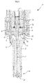
- Figure 3
- shows an exemplary embodiment of a damping element.
-
Figure 1 shows an exemplary embodiment of afluid injector 30 which comprises an O-ring or acirclip 32 for locking a spacer ring to avalve body 3, aspring element 34 in thevalve body 3 and acoil 36 in a housing which surrounds a portion of thevalve body 3. Thevalve body 3 has a longitudinal axis L. Thevalve body 3 has acircumferential side wall 5 which defines arecess 7. - The
injector 30 further comprises avalve needle 11 which is positioned in therecess 7. Thevalve needle 11 is connected to anarmature 9 and is axially movable relative to thevalve body 3 along the longitudinal axis L. In coaction with anozzle 38, thevalve needle 11 prevents a fluid flow through theinjector 30 in a closed position and is axially displaceable away from the closed position to enable it. - The
valve needle 11 is displaced away from the closed position ba means of a magnetic force generated by energizing thecoil 36 and is displaced towards the closing position by means of an elastic force generated by thespring element 34. A hydraulic force generated by the streaming fluid also influences the opening and closing process during an operation of theinjector 30, in particular when thevalve needle 11 is close to the closing position. Thevalve needle 11 and thearmature 9 are rigidly coupled or - as in the present embodiment - axially displaceable relative to one another. Specifically, thearmature 9 is axially arranged between an armature retainer of the valve needle and a dampingelement 13 which is fixed to a shaft of thevalve needle 11 so that it has an axial play. Thearmature 9, for example, is realized as a massive steel part from a magnetic steel. - A valve assembly 1 of the
fluid injector 30 comprises thearmature 9, thevalve needle 11, the dampingelement 13 and thevalve body 3. More detailed illustrations of the assembly 1 will be described below with respect tofigures 2 and3 . - In
figure 2 , one exemplary embodiment of the valve assembly 1 is illustrated wherein thearmature 9, the dampingelement 13 and thevalve needle 11 are arranged in therecess 7 of thevalve body 3. Thearmature 9 further comprises afirst opening 15 in which thevalve needle 11 is arranged as well as the dampingelement 13 comprises afirst opening 17 in which thevalve needle 11 is arranged. - In this exemplary embodiment of the assembly 1 in a cross section view with respect to the longitudinal axis L the
armature 9 comprises twosecond openings 16 which penetrate thearmature 9 axially from a first side - i.e. alower surface 24 of the armature 9 - to a second side - i.e. anupper surface 22 of thearmature 9. A central axis of each of thesecond openings 16 is inclined to the longitudinal axis L. - The damping
element 13 also comprises asecond opening 18 which penetrates the dampingelement 13 from a first side - i.e. anupper surface 25 of the damping element 13 - to asecond side 28 of the dampingelement 13. A central axis of thesecond opening 18 is parallel to and radially offset from the longitudinal axis L so that thesecond opening 18 is radially spaced apart from the longitudinal axis L. - In this exemplary embodiment the
valve needle 11 also comprises anopening 19 which extends axially through a portion of thevalve needle 11 and thus thevalve needle 11 acts as a hollow needle to enable fluid to pass through the assembly 1 during the operation of the assembly 1 or theinjector 30. Such a configuration of thevalve needle 11 is advantageous if for example the dampingelement 13 comprises nosecond openings 18 to let streaming fluid pass through. Alternatively, the streaming fluid can flow outside thearmature 9 and the dampingelement 13 if there is enough clearance left to thewall 5 of thevalve body 3. - This exemplary embodiment describes a combination of the
armature 9, thevalve needle 11 and the dampingelement 13 each comprising penetratingopenings second openings armature 9 and the dampingelement 13 arranged whereas thevalve needle 11 is substantially solid. Alternatively, there are only one or moresecond openings 16 arranged which penetrate thearmature 9 whereas thevalve needle 11 and the dampingelement 13 are substantially configures solidly. Hence, various combinations of thearmature 9, thevalve needle 11 and the dampingelement 13 are possible which do or do not comprise penetratingopenings - Furthermore, the damping
element 13 comprises a shape of a disc and is fixedly mounted on thevalve needle 11 for example by press fit, welding or machining. The dampingelement 13 further matches thearmature 9 concerning a lateral dimension of these components. This means that in this embodiment an outer outline of acircumferential side surface 21 of thearmature 9 is flush with an outer outline of acircumferential side surface 23 of the dampingelement 13 in top view along the longitudinal axis L. In addition, the dampingelement 13 nearly fills therecess 7 of thevalve body 3 in radial direction substantially perpendicular with respect to the longitudinal axis L. Preferably, only a small circumferential gap having a width - i.e. a radial dimension - of 0.5 mm or less, preferably of 0.2 mm or less, is established between theouter side surface 23 of the dampingelement 13 and an inner surface of thewall 5 of thevalve body 3. Such gap sizes are also useful for other embodiments of the valve assembly 1. - The
upper surface 25 of the dampingelement 13 has a ring-shapedprotrusion 27 which is engageable into a form-fit connection with thebottom surface 24 of thearmature 9. When theprotrusion 27 is in contact with thebottom surface 24 of thearmature 9, the rest of theupper surface 25 of the dampingelement 13 is spaced apart from thebottom surface 24 of thearmature 9 so that agap 26 is established between the twosurfaces protrusion 27. Theprotrusion 27 realizes a small contact surface to thearmature 9 in a shape of a slim ring. For example in a closed position of theinjector 30 theprotrusion 27 of the dampingelement 13 contacts thebottom surface 24 of thearmature 9. In this context, it is desirable that the contact surface is small enough to avoid hydraulic sticking of thearmature 9 and the dampingelement 13, but big enough to enable sufficient stability of the contact surface of the dampingelement 13 to avoid damages due temporary contact between thearmature 9 and the dampingelement 13. - In case of an opening transient, the
armature 9 moves upwards with respect to the longitudinal axis L, i.e. away from the dampingelement 13 due to the magnetic force generated by thecoil 36. For example after a preferred free lift of thearmature 9, thevalve needle 11 and the connected dampingelement 13 are also moved upwards due to the impact of thearmature 9 on the armature retainer. Thus, thevalve needle 11 is displaced away from the closing position and the streaming fluid mainly passes theopenings - Regarding this exemplary embodiment the
armature 9 comprises twosecond opening 16 whereas the dampingelement 13 comprises onesecond opening 18. It is advantageous that the respective number of thesecond openings element 13 and thearmature 9. For example, the twosecond openings 16 of thearmature 9 are designed as penetrating channels and the onesecond opening 18 of the dampingelement 13 is designed as a penetrating hole. Hence, there is at least one channel which guides the fluid into the recessedarea 26 and onto theupper surface 25 of the dampingelement 13 and not directly through thesecond opening 18. Due to this part of streaming fluid impacting on theupper surface 25 of the dampingelement 13 and being deflected in a lateral direction, fluid friction may be generated and/or the dampingelement 13 may be pushed away from thearmature 9 so that a hydraulic sticking of thearmature 9 and the dampingelement 13 is prevented. - The assembly 1 describes a simple, reliable and competitive possibility to reduce a velocity of the
valve needle 11 during an operation of the assembly 1 in reference to an opening process of theinjector 30 for example. The dampingelement 13 mounted on thevalve needle 11 decelerates the velocity of thevalve needle 11 due to enhanced flow resistance generated by the dampingelement 13 and the streaming fluid. Hence, the deceleration is generated by a force which is induced by the velocity of thevalve needle 11 itself. Therefore, using the assembly 1 enables a reliable and secure functioning of theinjector 30 with improved controllability. - An absolute value of the decelerating force can be chosen by the configuration of the damping
element 13, for example concerning a design or a shape of the dampingelement 13. Furthermore, the dampingelement 13 may comprise one or more recesses or openings like the describedsecond openings 18 to adjust the absolute value of the decelerating force. The dampingelement 13 is connected to thevalve needle 11. It may reduce the velocity of thevalve needle 11 during the opening and the closing transient. Theinjector 30 which comprises the valve assembly 1 exhibits an improved controllability in a ballistic phase of the opening transient or in a ballistic operation mode where thevalve needle 11 returns to the closing position without hitting a hard stop at the end of the opening transient. Hence, such a configuration allows for a fast opening of theinjector 30 also at high pressures combined with an enhanced controllability of thevalve needle 11 and the functioning of theinjector 30 which is advantageous to accurately dose the fluid for example. -
Figure 3 shows an exemplary embodiment of the dampingelement 13 which is similar to the one illustrated infigure 2 . The dampingelement 13 comprises five penetratingsecond openings 18 with circular shape which are arranged on a circle around the first penetratingopening 17 with respect to the longitudinal axis L. Thesecond openings 18 have a smaller diameter than thefirst opening 17 which is arranged for assembling thevalve needle 11 and which for example matches a diameter of the adjacentfirst opening 15 of thearmature 9. In this perspective view the contact surface between the dampingelement 13 and thearmature 9 given by theprotrusion 27 of the dampingelement 13 is apparent. This also concerns theupper surface 25 and its recessed area radially inward from theprotrusion 27, which recessed area shapes thegap 26 between the dampingelement 13 and thearmature 9. - Additionally, the damping
element 13 enables a stabilisation effect by guiding thevalve needle 11 in reference to thearmature 9 with respect to the longitudinal axis L. This is in particular effected by the outercircumferential side surface 23 of the dampingelement 13 being in sliding contact with thewall 5 of thevalve body 9. In this context, a large diameter of the disc shaped dampingelement 13 is advantageous because this enables a beneficial starting position of the connectedvalve needle 11 with respect to thearmature 9 due to leverage induced by the contact surface between thenose 27 of the dampingelement 13 and thefirst side 24 of thearmature 9. To enable a mentioned guiding effect, the dampingelement 13 of this embodiment comprise a small contact surface to thearmature 9 and nearly fills in therecess 7 of thevalve body 3, e.g. to realize an advantageous leverage.
Claims (11)
- Valve assembly (1) for a fluid injector comprising- a valve body (3) having a longitudinal axis (L) and comprising a wall (5) which forms a recess (7) that enables a streaming fluid pass the assembly (1) during an operation,- an armature (9),- a valve needle (11) having a needle tip (12) and- a damping element (13)
wherein- the armature (9) and the damping element (13) comprise penetrating first openings (15, 17) respectively, in which the valve needle (11) is arranged,- the armature (9), the valve needle (11) and the damping element (13) are arranged axially movable in the recess (7) with respect to the longitudinal axis (L) and relative to the valve body (3), and- the damping element (13) is fixed to the valve needle (11) and arranged between the armature (9) and the needle tip (12) with respect to the longitudinal axis (L) to attenuate a movement of the valve needle (11) relative to the valve body (3) during the operation of the assembly (1). - Valve assembly (1) in accordance with the preceding claim, wherein the damping element (13) substantially fills in the recess (7) of the valve body (3) in radial direction to generate a fluid friction for attenuating the movement of the valve needle (11).
- Valve assembly (1) in accordance with one of the preceding claims, wherein an outer circumferential outline (23) of the damping element (13) is arranged flush with an outer circumferential outline (21) of the armature (9).
- Valve assembly (1) according to one of the preceding claims, wherein the damping element (13) has an upper surface and the armature has a lower surface which face towards each other and which are spaced apart from one another apart from a region where the upper surface of the damping element (13) has a basically ring-shaped protrusion (27) which is engageable with the armature (9) so that it enters into a form-fit connection with the lower surface of the armature (9).
- Valve assembly (1) in accordance with one of the preceding claims, wherein the damping element (13) comprises at least one penetrating second opening (18) to enable the fluid to pass through the assembly (1) during the operation.
- Valve assembly (1) in accordance with one of the preceding claims, wherein the armature (9) comprises at least one penetrating second opening (16) to enable the fluid to pass through the assembly (1) during the operation.
- Valve assembly (1) in accordance with claims 5 and 6, wherein an outlet aperture of the second opening (16) of the armature (9) does not overlap or at most partially overlaps an inlet aperture of the second opening (18) of the damping element (13) in top view along the longitudinal axis (L).
- Valve assembly (1) in accordance with claim 7 or with claims 5 and 6, wherein a number of second openings (18) of the damping element (13) differs from a number of second openings (16) of the armature (9).
- Valve assembly (1) in accordance with one of the preceding claims, wherein the valve needle (11) comprises an axial channel (19) to enable the fluid passing the assembly (1) during the operation.
- Assembly (1) in accordance with one of the preceding claims, wherein the damping element (13) substantially has the shape of a disc.
- Fluid injector comprising a valve assembly according one of the preceding claims.
Priority Applications (6)
| Application Number | Priority Date | Filing Date | Title |
|---|---|---|---|
| EP14188946.9A EP3009663B1 (en) | 2014-10-15 | 2014-10-15 | Valve assembly and fluid injector |
| PCT/EP2015/068388 WO2016058726A1 (en) | 2014-10-15 | 2015-08-10 | Valve assembly and fluid injector |
| KR1020177010301A KR20170054515A (en) | 2014-10-15 | 2015-08-10 | Valve assembly and fluid injector |
| CN201580055695.6A CN107076078B (en) | 2014-10-15 | 2015-08-10 | Valve assembly and fluid injector |
| KR1020197004646A KR102072955B1 (en) | 2014-10-15 | 2015-08-10 | Valve assembly and fluid injector |
| US15/485,856 US10378498B2 (en) | 2014-10-15 | 2017-04-12 | Valve assembly and fluid injector |
Applications Claiming Priority (1)
| Application Number | Priority Date | Filing Date | Title |
|---|---|---|---|
| EP14188946.9A EP3009663B1 (en) | 2014-10-15 | 2014-10-15 | Valve assembly and fluid injector |
Publications (2)
| Publication Number | Publication Date |
|---|---|
| EP3009663A1 true EP3009663A1 (en) | 2016-04-20 |
| EP3009663B1 EP3009663B1 (en) | 2020-06-24 |
Family
ID=51690960
Family Applications (1)
| Application Number | Title | Priority Date | Filing Date |
|---|---|---|---|
| EP14188946.9A Active EP3009663B1 (en) | 2014-10-15 | 2014-10-15 | Valve assembly and fluid injector |
Country Status (5)
| Country | Link |
|---|---|
| US (1) | US10378498B2 (en) |
| EP (1) | EP3009663B1 (en) |
| KR (2) | KR102072955B1 (en) |
| CN (1) | CN107076078B (en) |
| WO (1) | WO2016058726A1 (en) |
Cited By (5)
| Publication number | Priority date | Publication date | Assignee | Title |
|---|---|---|---|---|
| WO2018001829A1 (en) * | 2016-06-30 | 2018-01-04 | Robert Bosch Gmbh | Valve for metering a fluid |
| EP3267026A1 (en) * | 2016-07-08 | 2018-01-10 | Continental Automotive GmbH | Valve assembly for an injection valve and injection valve |
| WO2018206382A1 (en) * | 2017-05-10 | 2018-11-15 | Robert Bosch Gmbh | Valve for metering a fluid |
| WO2019051767A1 (en) * | 2017-09-15 | 2019-03-21 | Robert Bosch Gmbh | Fuel injector and control valve thereof |
| EP3636911A1 (en) * | 2018-10-08 | 2020-04-15 | Continental Automotive GmbH | Valve assembly for an injection valve and fuel injection valve |
Families Citing this family (4)
| Publication number | Priority date | Publication date | Assignee | Title |
|---|---|---|---|---|
| DE102017222501A1 (en) * | 2017-12-12 | 2019-06-13 | Robert Bosch Gmbh | Valve for metering a fluid |
| JP6945743B2 (en) * | 2018-07-24 | 2021-10-06 | 日立Astemo株式会社 | Fuel injection valve |
| JP7143715B2 (en) | 2018-10-05 | 2022-09-29 | 株式会社デンソー | fuel injection valve and engine system |
| WO2022251503A1 (en) | 2021-05-28 | 2022-12-01 | Stanadyne Llc | Fuel injector |
Citations (5)
| Publication number | Priority date | Publication date | Assignee | Title |
|---|---|---|---|---|
| DE19927900A1 (en) * | 1999-06-18 | 2000-12-21 | Bosch Gmbh Robert | Fuel injection valve for direct injection IC engine has movement of armature limited by opposing stops attached to valve needle one of which is provided by spring element |
| EP1595072A1 (en) * | 2003-02-21 | 2005-11-16 | MAGNETI MARELLI POWERTRAIN S.p.A. | Fuel injector with an antirebound device |
| EP2436908A1 (en) * | 2010-09-30 | 2012-04-04 | Continental Automotive GmbH | Valve assembly for an injection valve and injection valve |
| EP2634413A1 (en) * | 2012-02-29 | 2013-09-04 | Robert Bosch Gmbh | Injector |
| WO2013167597A1 (en) * | 2012-05-08 | 2013-11-14 | Continental Automotive Gmbh | Valve assembly for an injection valve and injection valve |
Family Cites Families (9)
| Publication number | Priority date | Publication date | Assignee | Title |
|---|---|---|---|---|
| DE10118162B9 (en) * | 2001-04-11 | 2004-09-09 | Robert Bosch Gmbh | Fuel injector |
| EP1595972A1 (en) * | 2004-05-10 | 2005-11-16 | Precision Engineering AG | Process for treatment of metallic articles, particularly watch components |
| ATE423902T1 (en) * | 2006-12-12 | 2009-03-15 | Magneti Marelli Powertrain Spa | ELECTROMAGNETIC FUEL INJECTION VALVE FOR A DIRECT INJECTION INTERNAL COMBUSTION ENGINE |
| DE102010064105A1 (en) | 2010-12-23 | 2012-01-19 | Robert Bosch Gmbh | Valve for injecting fuel |
| EP2527637B1 (en) * | 2011-05-23 | 2014-10-08 | Continental Automotive GmbH | Injector for injecting fluid |
| EP2535552B1 (en) * | 2011-06-15 | 2015-02-25 | Continental Automotive GmbH | Valve assembly for an injection valve and injection valve |
| KR101345431B1 (en) * | 2011-12-09 | 2013-12-27 | 주식회사 현대케피코 | GDI fuel injector |
| ITBO20130169A1 (en) * | 2013-04-17 | 2014-10-18 | Magneti Marelli Spa | ELECTROMAGNETIC FUEL INJECTOR WITH BRAKING DEVICE |
| EP2949917B1 (en) | 2014-05-27 | 2017-01-04 | Continental Automotive GmbH | Fuel injector |
-
2014
- 2014-10-15 EP EP14188946.9A patent/EP3009663B1/en active Active
-
2015
- 2015-08-10 KR KR1020197004646A patent/KR102072955B1/en active IP Right Grant
- 2015-08-10 WO PCT/EP2015/068388 patent/WO2016058726A1/en active Application Filing
- 2015-08-10 CN CN201580055695.6A patent/CN107076078B/en active Active
- 2015-08-10 KR KR1020177010301A patent/KR20170054515A/en active Search and Examination
-
2017
- 2017-04-12 US US15/485,856 patent/US10378498B2/en active Active
Patent Citations (5)
| Publication number | Priority date | Publication date | Assignee | Title |
|---|---|---|---|---|
| DE19927900A1 (en) * | 1999-06-18 | 2000-12-21 | Bosch Gmbh Robert | Fuel injection valve for direct injection IC engine has movement of armature limited by opposing stops attached to valve needle one of which is provided by spring element |
| EP1595072A1 (en) * | 2003-02-21 | 2005-11-16 | MAGNETI MARELLI POWERTRAIN S.p.A. | Fuel injector with an antirebound device |
| EP2436908A1 (en) * | 2010-09-30 | 2012-04-04 | Continental Automotive GmbH | Valve assembly for an injection valve and injection valve |
| EP2634413A1 (en) * | 2012-02-29 | 2013-09-04 | Robert Bosch Gmbh | Injector |
| WO2013167597A1 (en) * | 2012-05-08 | 2013-11-14 | Continental Automotive Gmbh | Valve assembly for an injection valve and injection valve |
Cited By (18)
| Publication number | Priority date | Publication date | Assignee | Title |
|---|---|---|---|---|
| WO2018001829A1 (en) * | 2016-06-30 | 2018-01-04 | Robert Bosch Gmbh | Valve for metering a fluid |
| US10711750B2 (en) | 2016-06-30 | 2020-07-14 | Robert Bosch Gmbh | Valve for metering a fluid |
| EP3267026A1 (en) * | 2016-07-08 | 2018-01-10 | Continental Automotive GmbH | Valve assembly for an injection valve and injection valve |
| CN107587963A (en) * | 2016-07-08 | 2018-01-16 | 大陆汽车有限公司 | Valve module and injection valve for injection valve |
| KR20180006300A (en) * | 2016-07-08 | 2018-01-17 | 콘티넨탈 오토모티브 게엠베하 | Valve assembly for an injection valve and injection valve |
| US10550809B2 (en) | 2016-07-08 | 2020-02-04 | Vitesco Technologies GmbH | Valve assembly for an injection valve and injection valve |
| KR101967982B1 (en) | 2016-07-08 | 2019-04-10 | 콘티넨탈 오토모티브 게엠베하 | Valve assembly for an injection valve and injection valve |
| CN107587963B (en) * | 2016-07-08 | 2019-11-15 | 大陆汽车有限公司 | Valve module and injection valve for injection valve |
| CN110612390A (en) * | 2017-05-10 | 2019-12-24 | 罗伯特·博世有限公司 | Valve for metering a fluid |
| WO2018206382A1 (en) * | 2017-05-10 | 2018-11-15 | Robert Bosch Gmbh | Valve for metering a fluid |
| EP3779172A1 (en) * | 2017-05-10 | 2021-02-17 | Robert Bosch GmbH | Valve for metering a fluid |
| CN110612390B (en) * | 2017-05-10 | 2022-05-31 | 罗伯特·博世有限公司 | Valve for metering a fluid |
| EP4033087A1 (en) * | 2017-05-10 | 2022-07-27 | Robert Bosch GmbH | Valve for metering a fluid |
| CN114876689A (en) * | 2017-05-10 | 2022-08-09 | 罗伯特·博世有限公司 | Valve for metering a fluid |
| CN114876689B (en) * | 2017-05-10 | 2023-09-01 | 罗伯特·博世有限公司 | Valve for metering fluids |
| US11852106B2 (en) | 2017-05-10 | 2023-12-26 | Robert Bosch Gmbh | Valve for metering a fluid |
| WO2019051767A1 (en) * | 2017-09-15 | 2019-03-21 | Robert Bosch Gmbh | Fuel injector and control valve thereof |
| EP3636911A1 (en) * | 2018-10-08 | 2020-04-15 | Continental Automotive GmbH | Valve assembly for an injection valve and fuel injection valve |
Also Published As
| Publication number | Publication date |
|---|---|
| KR102072955B1 (en) | 2020-02-03 |
| WO2016058726A1 (en) | 2016-04-21 |
| US20170218902A1 (en) | 2017-08-03 |
| US10378498B2 (en) | 2019-08-13 |
| CN107076078B (en) | 2020-03-27 |
| EP3009663B1 (en) | 2020-06-24 |
| CN107076078A (en) | 2017-08-18 |
| KR20170054515A (en) | 2017-05-17 |
| KR20190018765A (en) | 2019-02-25 |
Similar Documents
| Publication | Publication Date | Title |
|---|---|---|
| US10378498B2 (en) | Valve assembly and fluid injector | |
| EP2796703B1 (en) | Valve assembly for an injection valve and injection valve | |
| KR20150136581A (en) | Fuel injector | |
| KR101967982B1 (en) | Valve assembly for an injection valve and injection valve | |
| US9995262B2 (en) | Fluid injection valve | |
| KR20150048207A (en) | Valve assembly for an injection valve and injection valve | |
| US10570862B2 (en) | Valve assembly and fluid injection valve | |
| CN107923354B (en) | Valve for metering a fluid | |
| EP3260695B1 (en) | Valve assembly for an injection valve and injection valve | |
| KR101949061B1 (en) | Injector for injecting fluid | |
| KR102170838B1 (en) | Valve assembly for injection valve and injection valve | |
| EP3279462B1 (en) | Filter assembly for an injection valve, valve assembly and injection valve | |
| EP3156638A1 (en) | Fuel injector | |
| CN110030131B (en) | Valve for metering a fluid | |
| JP6409068B2 (en) | Fuel injection nozzle | |
| KR20230043253A (en) | Valve for metering a fluid | |
| WO2015039859A1 (en) | Valve assembly for an injection valve and injection valve | |
| EP3339627A1 (en) | Valve assembly and fluid injection valve | |
| EP3636911A1 (en) | Valve assembly for an injection valve and fuel injection valve | |
| EP2241743B1 (en) | Valve assembly for an injection valve and injection valve | |
| KR20190039797A (en) | Valve assembly and injection valve for injection valve | |
| EP2703633A1 (en) | Valve assembly for an injection valve and injection valve |
Legal Events
| Date | Code | Title | Description |
|---|---|---|---|
| PUAI | Public reference made under article 153(3) epc to a published international application that has entered the european phase |
Free format text: ORIGINAL CODE: 0009012 |
|
| AK | Designated contracting states |
Kind code of ref document: A1 Designated state(s): AL AT BE BG CH CY CZ DE DK EE ES FI FR GB GR HR HU IE IS IT LI LT LU LV MC MK MT NL NO PL PT RO RS SE SI SK SM TR |
|
| AX | Request for extension of the european patent |
Extension state: BA ME |
|
| 17P | Request for examination filed |
Effective date: 20161020 |
|
| RBV | Designated contracting states (corrected) |
Designated state(s): AL AT BE BG CH CY CZ DE DK EE ES FI FR GB GR HR HU IE IS IT LI LT LU LV MC MK MT NL NO PL PT RO RS SE SI SK SM TR |
|
| STAA | Information on the status of an ep patent application or granted ep patent |
Free format text: STATUS: EXAMINATION IS IN PROGRESS |
|
| 17Q | First examination report despatched |
Effective date: 20180806 |
|
| GRAP | Despatch of communication of intention to grant a patent |
Free format text: ORIGINAL CODE: EPIDOSNIGR1 |
|
| STAA | Information on the status of an ep patent application or granted ep patent |
Free format text: STATUS: GRANT OF PATENT IS INTENDED |
|
| INTG | Intention to grant announced |
Effective date: 20200124 |
|
| RAP1 | Party data changed (applicant data changed or rights of an application transferred) |
Owner name: VITESCO TECHNOLOGIES GMBH |
|
| GRAS | Grant fee paid |
Free format text: ORIGINAL CODE: EPIDOSNIGR3 |
|
| GRAA | (expected) grant |
Free format text: ORIGINAL CODE: 0009210 |
|
| STAA | Information on the status of an ep patent application or granted ep patent |
Free format text: STATUS: THE PATENT HAS BEEN GRANTED |
|
| AK | Designated contracting states |
Kind code of ref document: B1 Designated state(s): AL AT BE BG CH CY CZ DE DK EE ES FI FR GB GR HR HU IE IS IT LI LT LU LV MC MK MT NL NO PL PT RO RS SE SI SK SM TR |
|
| REG | Reference to a national code |
Ref country code: GB Ref legal event code: FG4D |
|
| REG | Reference to a national code |
Ref country code: CH Ref legal event code: EP |
|
| REG | Reference to a national code |
Ref country code: AT Ref legal event code: REF Ref document number: 1284127 Country of ref document: AT Kind code of ref document: T Effective date: 20200715 |
|
| REG | Reference to a national code |
Ref country code: DE Ref legal event code: R096 Ref document number: 602014066925 Country of ref document: DE |
|
| REG | Reference to a national code |
Ref country code: IE Ref legal event code: FG4D |
|
| PG25 | Lapsed in a contracting state [announced via postgrant information from national office to epo] |
Ref country code: GR Free format text: LAPSE BECAUSE OF FAILURE TO SUBMIT A TRANSLATION OF THE DESCRIPTION OR TO PAY THE FEE WITHIN THE PRESCRIBED TIME-LIMIT Effective date: 20200925 Ref country code: NO Free format text: LAPSE BECAUSE OF FAILURE TO SUBMIT A TRANSLATION OF THE DESCRIPTION OR TO PAY THE FEE WITHIN THE PRESCRIBED TIME-LIMIT Effective date: 20200924 Ref country code: SE Free format text: LAPSE BECAUSE OF FAILURE TO SUBMIT A TRANSLATION OF THE DESCRIPTION OR TO PAY THE FEE WITHIN THE PRESCRIBED TIME-LIMIT Effective date: 20200624 Ref country code: LT Free format text: LAPSE BECAUSE OF FAILURE TO SUBMIT A TRANSLATION OF THE DESCRIPTION OR TO PAY THE FEE WITHIN THE PRESCRIBED TIME-LIMIT Effective date: 20200624 Ref country code: FI Free format text: LAPSE BECAUSE OF FAILURE TO SUBMIT A TRANSLATION OF THE DESCRIPTION OR TO PAY THE FEE WITHIN THE PRESCRIBED TIME-LIMIT Effective date: 20200624 |
|
| REG | Reference to a national code |
Ref country code: LT Ref legal event code: MG4D |
|
| PG25 | Lapsed in a contracting state [announced via postgrant information from national office to epo] |
Ref country code: LV Free format text: LAPSE BECAUSE OF FAILURE TO SUBMIT A TRANSLATION OF THE DESCRIPTION OR TO PAY THE FEE WITHIN THE PRESCRIBED TIME-LIMIT Effective date: 20200624 Ref country code: RS Free format text: LAPSE BECAUSE OF FAILURE TO SUBMIT A TRANSLATION OF THE DESCRIPTION OR TO PAY THE FEE WITHIN THE PRESCRIBED TIME-LIMIT Effective date: 20200624 Ref country code: BG Free format text: LAPSE BECAUSE OF FAILURE TO SUBMIT A TRANSLATION OF THE DESCRIPTION OR TO PAY THE FEE WITHIN THE PRESCRIBED TIME-LIMIT Effective date: 20200924 Ref country code: HR Free format text: LAPSE BECAUSE OF FAILURE TO SUBMIT A TRANSLATION OF THE DESCRIPTION OR TO PAY THE FEE WITHIN THE PRESCRIBED TIME-LIMIT Effective date: 20200624 |
|
| REG | Reference to a national code |
Ref country code: NL Ref legal event code: MP Effective date: 20200624 |
|
| REG | Reference to a national code |
Ref country code: AT Ref legal event code: MK05 Ref document number: 1284127 Country of ref document: AT Kind code of ref document: T Effective date: 20200624 |
|
| PG25 | Lapsed in a contracting state [announced via postgrant information from national office to epo] |
Ref country code: NL Free format text: LAPSE BECAUSE OF FAILURE TO SUBMIT A TRANSLATION OF THE DESCRIPTION OR TO PAY THE FEE WITHIN THE PRESCRIBED TIME-LIMIT Effective date: 20200624 Ref country code: AL Free format text: LAPSE BECAUSE OF FAILURE TO SUBMIT A TRANSLATION OF THE DESCRIPTION OR TO PAY THE FEE WITHIN THE PRESCRIBED TIME-LIMIT Effective date: 20200624 |
|
| PG25 | Lapsed in a contracting state [announced via postgrant information from national office to epo] |
Ref country code: CZ Free format text: LAPSE BECAUSE OF FAILURE TO SUBMIT A TRANSLATION OF THE DESCRIPTION OR TO PAY THE FEE WITHIN THE PRESCRIBED TIME-LIMIT Effective date: 20200624 Ref country code: ES Free format text: LAPSE BECAUSE OF FAILURE TO SUBMIT A TRANSLATION OF THE DESCRIPTION OR TO PAY THE FEE WITHIN THE PRESCRIBED TIME-LIMIT Effective date: 20200624 Ref country code: RO Free format text: LAPSE BECAUSE OF FAILURE TO SUBMIT A TRANSLATION OF THE DESCRIPTION OR TO PAY THE FEE WITHIN THE PRESCRIBED TIME-LIMIT Effective date: 20200624 Ref country code: SM Free format text: LAPSE BECAUSE OF FAILURE TO SUBMIT A TRANSLATION OF THE DESCRIPTION OR TO PAY THE FEE WITHIN THE PRESCRIBED TIME-LIMIT Effective date: 20200624 Ref country code: EE Free format text: LAPSE BECAUSE OF FAILURE TO SUBMIT A TRANSLATION OF THE DESCRIPTION OR TO PAY THE FEE WITHIN THE PRESCRIBED TIME-LIMIT Effective date: 20200624 Ref country code: AT Free format text: LAPSE BECAUSE OF FAILURE TO SUBMIT A TRANSLATION OF THE DESCRIPTION OR TO PAY THE FEE WITHIN THE PRESCRIBED TIME-LIMIT Effective date: 20200624 Ref country code: PT Free format text: LAPSE BECAUSE OF FAILURE TO SUBMIT A TRANSLATION OF THE DESCRIPTION OR TO PAY THE FEE WITHIN THE PRESCRIBED TIME-LIMIT Effective date: 20201026 |
|
| PG25 | Lapsed in a contracting state [announced via postgrant information from national office to epo] |
Ref country code: SK Free format text: LAPSE BECAUSE OF FAILURE TO SUBMIT A TRANSLATION OF THE DESCRIPTION OR TO PAY THE FEE WITHIN THE PRESCRIBED TIME-LIMIT Effective date: 20200624 Ref country code: PL Free format text: LAPSE BECAUSE OF FAILURE TO SUBMIT A TRANSLATION OF THE DESCRIPTION OR TO PAY THE FEE WITHIN THE PRESCRIBED TIME-LIMIT Effective date: 20200624 Ref country code: IS Free format text: LAPSE BECAUSE OF FAILURE TO SUBMIT A TRANSLATION OF THE DESCRIPTION OR TO PAY THE FEE WITHIN THE PRESCRIBED TIME-LIMIT Effective date: 20201024 |
|
| REG | Reference to a national code |
Ref country code: DE Ref legal event code: R097 Ref document number: 602014066925 Country of ref document: DE |
|
| PG25 | Lapsed in a contracting state [announced via postgrant information from national office to epo] |
Ref country code: DK Free format text: LAPSE BECAUSE OF FAILURE TO SUBMIT A TRANSLATION OF THE DESCRIPTION OR TO PAY THE FEE WITHIN THE PRESCRIBED TIME-LIMIT Effective date: 20200624 |
|
| PLBE | No opposition filed within time limit |
Free format text: ORIGINAL CODE: 0009261 |
|
| STAA | Information on the status of an ep patent application or granted ep patent |
Free format text: STATUS: NO OPPOSITION FILED WITHIN TIME LIMIT |
|
| REG | Reference to a national code |
Ref country code: CH Ref legal event code: PL |
|
| 26N | No opposition filed |
Effective date: 20210325 |
|
| PG25 | Lapsed in a contracting state [announced via postgrant information from national office to epo] |
Ref country code: LU Free format text: LAPSE BECAUSE OF NON-PAYMENT OF DUE FEES Effective date: 20201015 Ref country code: MC Free format text: LAPSE BECAUSE OF FAILURE TO SUBMIT A TRANSLATION OF THE DESCRIPTION OR TO PAY THE FEE WITHIN THE PRESCRIBED TIME-LIMIT Effective date: 20200624 |
|
| REG | Reference to a national code |
Ref country code: BE Ref legal event code: MM Effective date: 20201031 |
|
| PG25 | Lapsed in a contracting state [announced via postgrant information from national office to epo] |
Ref country code: CH Free format text: LAPSE BECAUSE OF NON-PAYMENT OF DUE FEES Effective date: 20201031 Ref country code: BE Free format text: LAPSE BECAUSE OF NON-PAYMENT OF DUE FEES Effective date: 20201031 Ref country code: SI Free format text: LAPSE BECAUSE OF FAILURE TO SUBMIT A TRANSLATION OF THE DESCRIPTION OR TO PAY THE FEE WITHIN THE PRESCRIBED TIME-LIMIT Effective date: 20200624 Ref country code: LI Free format text: LAPSE BECAUSE OF NON-PAYMENT OF DUE FEES Effective date: 20201031 |
|
| PG25 | Lapsed in a contracting state [announced via postgrant information from national office to epo] |
Ref country code: IE Free format text: LAPSE BECAUSE OF NON-PAYMENT OF DUE FEES Effective date: 20201015 |
|
| REG | Reference to a national code |
Ref country code: DE Ref legal event code: R081 Ref document number: 602014066925 Country of ref document: DE Owner name: VITESCO TECHNOLOGIES GMBH, DE Free format text: FORMER OWNER: VITESCO TECHNOLOGIES GMBH, 30165 HANNOVER, DE |
|
| PG25 | Lapsed in a contracting state [announced via postgrant information from national office to epo] |
Ref country code: TR Free format text: LAPSE BECAUSE OF FAILURE TO SUBMIT A TRANSLATION OF THE DESCRIPTION OR TO PAY THE FEE WITHIN THE PRESCRIBED TIME-LIMIT Effective date: 20200624 Ref country code: MT Free format text: LAPSE BECAUSE OF FAILURE TO SUBMIT A TRANSLATION OF THE DESCRIPTION OR TO PAY THE FEE WITHIN THE PRESCRIBED TIME-LIMIT Effective date: 20200624 Ref country code: CY Free format text: LAPSE BECAUSE OF FAILURE TO SUBMIT A TRANSLATION OF THE DESCRIPTION OR TO PAY THE FEE WITHIN THE PRESCRIBED TIME-LIMIT Effective date: 20200624 |
|
| PG25 | Lapsed in a contracting state [announced via postgrant information from national office to epo] |
Ref country code: MK Free format text: LAPSE BECAUSE OF FAILURE TO SUBMIT A TRANSLATION OF THE DESCRIPTION OR TO PAY THE FEE WITHIN THE PRESCRIBED TIME-LIMIT Effective date: 20200624 |
|
| P01 | Opt-out of the competence of the unified patent court (upc) registered |
Effective date: 20230530 |
|
| PGFP | Annual fee paid to national office [announced via postgrant information from national office to epo] |
Ref country code: GB Payment date: 20231020 Year of fee payment: 10 |
|
| PGFP | Annual fee paid to national office [announced via postgrant information from national office to epo] |
Ref country code: IT Payment date: 20231026 Year of fee payment: 10 Ref country code: FR Payment date: 20231026 Year of fee payment: 10 Ref country code: DE Payment date: 20231031 Year of fee payment: 10 |