EP3009582B1 - Dispositif d'entretoisement pour la fixation d'un profilé de support d'une cloison de doublage d'une paroi à isoler - Google Patents
Dispositif d'entretoisement pour la fixation d'un profilé de support d'une cloison de doublage d'une paroi à isoler Download PDFInfo
- Publication number
- EP3009582B1 EP3009582B1 EP15189652.9A EP15189652A EP3009582B1 EP 3009582 B1 EP3009582 B1 EP 3009582B1 EP 15189652 A EP15189652 A EP 15189652A EP 3009582 B1 EP3009582 B1 EP 3009582B1
- Authority
- EP
- European Patent Office
- Prior art keywords
- rod
- head
- wall
- supporting
- membrane
- Prior art date
- Legal status (The legal status is an assumption and is not a legal conclusion. Google has not performed a legal analysis and makes no representation as to the accuracy of the status listed.)
- Active
Links
- 238000005192 partition Methods 0.000 title claims description 5
- 125000006850 spacer group Chemical group 0.000 claims description 39
- 239000012528 membrane Substances 0.000 claims description 38
- 238000009413 insulation Methods 0.000 claims description 24
- 239000002184 metal Substances 0.000 claims description 12
- 239000000463 material Substances 0.000 claims description 6
- 230000004888 barrier function Effects 0.000 claims description 5
- 230000002093 peripheral effect Effects 0.000 claims description 5
- 239000011324 bead Substances 0.000 claims description 3
- 239000002991 molded plastic Substances 0.000 claims description 3
- 238000004873 anchoring Methods 0.000 claims description 2
- 230000003014 reinforcing effect Effects 0.000 claims description 2
- 238000000926 separation method Methods 0.000 claims 5
- 230000000903 blocking effect Effects 0.000 claims 1
- 238000007789 sealing Methods 0.000 description 15
- 238000009434 installation Methods 0.000 description 5
- BASFCYQUMIYNBI-UHFFFAOYSA-N platinum Chemical compound [Pt] BASFCYQUMIYNBI-UHFFFAOYSA-N 0.000 description 5
- 235000002790 Monstera deliciosa Nutrition 0.000 description 4
- 240000000987 Monstera deliciosa Species 0.000 description 4
- 239000002657 fibrous material Substances 0.000 description 4
- 239000012212 insulator Substances 0.000 description 3
- 239000004033 plastic Substances 0.000 description 3
- 229920003023 plastic Polymers 0.000 description 3
- XLYOFNOQVPJJNP-UHFFFAOYSA-N water Substances O XLYOFNOQVPJJNP-UHFFFAOYSA-N 0.000 description 3
- 101100219325 Phaseolus vulgaris BA13 gene Proteins 0.000 description 2
- 230000002411 adverse Effects 0.000 description 1
- 238000004378 air conditioning Methods 0.000 description 1
- 210000000080 chela (arthropods) Anatomy 0.000 description 1
- 238000010276 construction Methods 0.000 description 1
- 230000001627 detrimental effect Effects 0.000 description 1
- 238000005553 drilling Methods 0.000 description 1
- 230000005611 electricity Effects 0.000 description 1
- 238000005516 engineering process Methods 0.000 description 1
- 239000000835 fiber Substances 0.000 description 1
- 238000009432 framing Methods 0.000 description 1
- 239000011521 glass Substances 0.000 description 1
- 229910052602 gypsum Inorganic materials 0.000 description 1
- 239000010440 gypsum Substances 0.000 description 1
- 238000002513 implantation Methods 0.000 description 1
- 238000007373 indentation Methods 0.000 description 1
- 230000000977 initiatory effect Effects 0.000 description 1
- 239000012774 insulation material Substances 0.000 description 1
- 238000012423 maintenance Methods 0.000 description 1
- 238000004519 manufacturing process Methods 0.000 description 1
- 239000011490 mineral wool Substances 0.000 description 1
- 238000009418 renovation Methods 0.000 description 1
- 239000000725 suspension Substances 0.000 description 1
- 238000009423 ventilation Methods 0.000 description 1
- 238000004078 waterproofing Methods 0.000 description 1
Images


Classifications
-
- E—FIXED CONSTRUCTIONS
- E04—BUILDING
- E04F—FINISHING WORK ON BUILDINGS, e.g. STAIRS, FLOORS
- E04F13/00—Coverings or linings, e.g. for walls or ceilings
- E04F13/07—Coverings or linings, e.g. for walls or ceilings composed of covering or lining elements; Sub-structures therefor; Fastening means therefor
- E04F13/08—Coverings or linings, e.g. for walls or ceilings composed of covering or lining elements; Sub-structures therefor; Fastening means therefor composed of a plurality of similar covering or lining elements
- E04F13/0801—Separate fastening elements
- E04F13/0803—Separate fastening elements with load-supporting elongated furring elements between wall and covering elements
- E04F13/0805—Separate fastening elements with load-supporting elongated furring elements between wall and covering elements with additional fastening elements between furring elements and the wall
-
- E—FIXED CONSTRUCTIONS
- E04—BUILDING
- E04D—ROOF COVERINGS; SKY-LIGHTS; GUTTERS; ROOF-WORKING TOOLS
- E04D13/00—Special arrangements or devices in connection with roof coverings; Protection against birds; Roof drainage ; Sky-lights
- E04D13/16—Insulating devices or arrangements in so far as the roof covering is concerned, e.g. characterised by the material or composition of the roof insulating material or its integration in the roof structure
- E04D13/1606—Insulation of the roof covering characterised by its integration in the roof structure
- E04D13/1612—Insulation of the roof covering characterised by its integration in the roof structure the roof structure comprising a supporting framework of roof purlins or rafters
- E04D13/1637—Insulation of the roof covering characterised by its integration in the roof structure the roof structure comprising a supporting framework of roof purlins or rafters the roof purlins or rafters being mainly insulated from the interior, e.g. the insulating material being fixed under or suspended from the supporting framework
-
- E—FIXED CONSTRUCTIONS
- E04—BUILDING
- E04B—GENERAL BUILDING CONSTRUCTIONS; WALLS, e.g. PARTITIONS; ROOFS; FLOORS; CEILINGS; INSULATION OR OTHER PROTECTION OF BUILDINGS
- E04B1/00—Constructions in general; Structures which are not restricted either to walls, e.g. partitions, or floors or ceilings or roofs
- E04B1/62—Insulation or other protection; Elements or use of specified material therefor
- E04B1/74—Heat, sound or noise insulation, absorption, or reflection; Other building methods affording favourable thermal or acoustical conditions, e.g. accumulating of heat within walls
- E04B1/76—Heat, sound or noise insulation, absorption, or reflection; Other building methods affording favourable thermal or acoustical conditions, e.g. accumulating of heat within walls specifically with respect to heat only
- E04B1/7675—Insulating linings for the interior face of exterior walls
Definitions
- the present invention relates to a bracing device for the adjustable fixing of a support profile of a lining wall remote from a wall to be doubled by a thermal and / or sound insulation of fibrous type.
- these rails must be fixed to said wall to be insulated, for example to beams such as rafters or ceiling joists, using spacers that maintain the insulation and a membrane membrane -air (wind and / or vapor barrier) between the lining wall and the wall to be doubled.
- This membrane is most often interposed between the layer of fibrous material and the lining wall, typically contiguous to the partition, optionally interposed between two layers of fibrous material.
- multiple regularly spaced spacers are used.
- Each spacer typically comprises a rod-shaped main body extending transversely to the wall to be doubled and to the doubling wall, one end of which is provided with means for attachment to a structural element of the wall to be doubled and whose another end is provided with means for supporting the metal backing frame.
- a bracing accessory is for example known documents WO2006 / 061538 and FR2925929A1 .
- the insulation complex is socketed on the rod of each spacer accessory, which causes multiple piercing layers of fibrous material and, where appropriate, the air barrier membrane.
- This piercing is particularly detrimental with regard to the membranes, because their function sealing, permanent or selective, is then altered.
- the piercing of the membrane may further constitute a tear initiation likely to spread if too much tension is exerted.
- the membrane on the inner side of the metal frame, between the latter and the lining wall.
- the membrane is not pierced by a spacer and can remain intact, at least initially.
- the attachment of the lining wall to the metal frame involves the piercing of the membrane by fasteners (staples, or self-drilling screws for example), which, although to a lesser extent, adversely affects sealing of the membrane.
- An object of the present invention is therefore to solve the problems mentioned above, using a simple solution to manufacture, inexpensive, easy to implement and optimized in terms efficiency, particularly with respect to the integrity and sealing of the membrane while providing a sufficiently large space and accessible behind the lining wall to pass accessories such as cables or pipes.
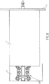
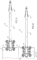
- the figures 1 and 2 represent a spacer 10 (also called suspension) according to the present invention and for adjustably fixing a support profile of a lining wall remote from a wall to be doubled by a thermal and / or acoustic insulation fibrous type .
- This spacer 10 comprises a mounting plate 20 extending at a rear end 11, by a main longitudinal rod 30 terminating at a front end 12 by a tip 32.
- the spacer 10 measures a few centimeters to a few tens of centimeters, preferably between about 10 cm and 40 cm, for example 20 cm, the rod alone measuring about 15 cm in this case.
- the tip 32 of the rod 30 has notches 33 distributed evenly around its periphery.
- the rod 30 consists of a metal core (not visible), for example a threaded rod, covered by overmolding with a thin layer of plastic material 31.
- the spacer 10 comprises, near its front end 12, two harpoons 40 arranged radially on the rod 30 and allowing, as will be described later, to be planted in a fibrous insulation to prevent it from moving and / or detaches from the wall to be insulated.
- the tip 41 of each harpoon 40 is oriented towards the rear end 11 of the spacer 10.
- the harpoons 40 are raised radially on the rod 30 by a few millimeters, for example 1 to 5 mm, preferably 2 to 3 mm.
- the two harpoons 40 are identical and located on either side of the rod 30, in the same radial plane parallel to the fixing plate 20.
- the spacer 10 also comprises, beyond the harpoons 40, a radial stop ring 50 formed by a molded plastic ring undeformable (that is to say non-elastic).
- a radial stop ring 50 formed by a molded plastic ring undeformable (that is to say non-elastic).
- the outer diameter of this ring 50 is greater by a few millimeters than that of the rod 30, for example from 0.5 to 3 mm and preferably from approximately 1 to 2 mm.
- the mounting plate 20 has two fins 22 arranged radially on the rod 30 and formed integrally therewith during overmoulding of plastics material.
- Each fin 22 comprises a first series of orifices 24 aligned parallel to the rod and two end lugs 25 each having an orifice 26 further from the rod than the first series of orifices 24.
- the mounting plate 20 also comprises pins 28 defining the positioning limits of the spacer 10 on the wall to be doubled, for example on a beam such as a chevron.
- These marks 28 are constituted by two lines of plastic material in overthickness oriented perpendicular to the rod 30 and spaced a few centimeters, for example between 1 and 8 cm, preferably about 2 to 5 cm, for example 4 cm. They allow to adjust the positioning of the spacer according to the dimensions of the structure on which it is fixed and the thickness of the insulation used.
- the spacer 10 finally comprises an independent head 60 (also called cap or key) provided for, in the use position, irreversibly clipping or dismountable around the rod 30, against the radial stop ring 50, like this will be described later.
- an independent head 60 also called cap or key
- the head 60 has a domed end portion 61 provided with a peripheral groove 62 in which can slide a support section 8 such as a metal rail "C" of known type on which is screwed a doubling wall such as a plasterboard.
- a support section 8 such as a metal rail "C" of known type on which is screwed a doubling wall such as a plasterboard.
- the head 60 is provided with a first annular seal 64 formed on a nip surface 65 facing the radial stop ring 50 and bearing on the latter in the active position of use.
- the head 60 is also provided on the nip surface 65 with a second annular seal 66 coaxial with the first seal 64 and disposed substantially at the periphery of said nip surface.
- Each seal 64 and 66 is constituted by an overmolded elastomeric bead protruding from the gripping surface 65 and ensuring a good airtightness.
- the head 60 further has an axial space 68 between the base 63 of the dome 61 and the nip surface 65, said gap 68 being between about 5 mm and 20 mm, preferably between 10 and 15 mm.
- the spacer 10 is fixed cantilevered on the wall to be insulated, in particular on a chevron 5 framing.
- the installer place the plate 20 perpendicular to the flank of the chevron 5 and positions it using the pins 28 to adjust the length that will exceed the chevron.
- the marks 28 thus make it possible to delimit the minimum and maximum distances for positioning the spacer 10 with respect to the edge of the chevron 5, as illustrated by the Figures 11 and 12 .
- the latter can take all possible positions between these two limits to adapt to the conditions of implantation of the insulation and the lining wall without harming its fixing. Beyond the limits, especially if the spacer 10 protrudes too much from the chevron 5, the attachment may be insufficient, or even detach or break.
- the installer fixes the spacer 10 in the side of the chevron 5 by placing screws (not shown) through the orifices 24 and 26. For this, it is advisable to distribute the screws longitudinally and on either side of the central rod 30.
- the screws are placed at the ends of each fin 22, that is to say in the orifices 26 of the lugs 25. Four screws are sufficient but it is possible to add in the other 24 holes available to strengthen the attachment.
- the installer repeats these positioning and screwing operations for each spacer 10 along the various rafters of the wall to be insulated.
- the installer is stuck on it fibrous insulation 2, for example based on rock wool or glass.
- fibrous insulation for example based on rock wool or glass.
- This operation illustrated by reference 2 of the figure 5 and by figure 7 , is facilitated by the notched tip 32 of the front end 12 of each spacer 10.
- the installer bears on the insulator 2 so that the harpoons 40 clings into the fibers.
- the fibrous insulation material 2 remains well held in place thanks to the points 41 of the harpoons 40. avoids falling, which could reduce the quality of the insulation.
- an air barrier membrane 3 By also attaching it to the pointed front end 32 of each spacer 10, as represented by the reference 3 of the figure 5 and by figure 8 .
- This membrane of known type has a permeance to water vapor varying according to the ambient humidity. During this operation, it is important to ensure that the sealing membrane 3 does not protrude through the radial stop ring 50 against which it must rest. Thus, the sealing membrane 3 is slightly spaced from the insulator 2.
- the orifice formed during the perforation by the spacer 10 closes around of the rod 30, which contributes to good thermal insulation.
- the thickness of this kind of membrane is typically between 5 and 600 micrometers.
- the assembly consisting of the layer of fibrous material and the sealing membrane is commonly called insulation complex.
- the sealing membrane 3 being placed, the installer comes to block it by clipping the head 60 of each spacer 10 on its rod 30.
- the gripping surface 65 comes into contact with the sealing membrane 3 and forms, with the radial stop ring 50, a jaw.
- the sealing membrane 3 is sandwiched between the radially stable stop ring 50 and the gripping surface 65 of the head 60 on a continuous contact surface.
- the two seals 64 and 66 of the gripping surface 65 of the head 60 make it possible to avoid heat losses (fresh or hot air).
- the smallest peripheral seal 64 is substantially of the same external diameter as that of the radial stop ring 50 so as to trap the sealing membrane 3 between them.
- the installer can position support rails 8 in "C” of known type (also called furs) by inserting the branches of the "C” in the peripheral groove 62 of each head, as shown in reference 5 of the figure 5 and on the figure 10 .
- sealing membrane 3 is disposed at a distance from the rails, and therefore the facing plates.
- the vacuum zone provided between the waterproofing membrane 3 and the rails / gypsum boards also significantly improves the thermal and / or acoustic insulation of the lining and thus of the part to be insulated.
- the present invention it is possible to thermally and / or acoustically insulate a wall such as a wall, a frame or a ceiling, using spacers 10 easy to use, robust and adjustable. Because of the design of these spacers 10, the fibrous insulation 2 is perfectly maintained in place thanks to the numerous harpoons 40.
- the sealing membrane 3 is also positioned in an optimized manner to ensure good insulation.
- the axial space 68 of the head 60 makes it possible to place various cables or pipes and to modify them or to add / remove them if need without risk of perforating the sealing membrane 3.
- this spacer 10 is adapted to the support rails usual.
- the head 60 can be removably attached to the rod 30 of the spacer 10.
- the head 60 is provided with through radial apertures 67 and 69 for receiving a key 70 illustrated in detail on the figure 16 ). More specifically, the head 60 has in its structure, at the axial space 68, a first inlet opening 67 and, on the opposite side, two smaller outlet openings 69 aligned with the inlet opening 67 The inlet opening 67 is substantially wider than the total width of the two outlet openings 69.
- the installer When the installer wishes to complete the installation of a spacer 10 whose rod 30 is fixed on a chevron as described above, it assembles the head 60 on the end of the rod 30 in order to abut the pinch surface 65 with the radial stop ring 50, then it introduces the key 70 in the inlet opening 67.
- the branches 72 of the key being elastically deformable, they move radially to the passage of the rod 30 and then come closing around the latter before coming out of the head 60 through the outlet openings 69.
- the key 70 comprises a hollow inner portion 75 with a circular section which engages the rod 30, which for this purpose has substantially the same diameter.
- the head 60 is locked axially on the rod 30 so that it is then possible to come up the support rails of the insulation plates.
- the rod may comprise more than two harpoons, for example four, or arranged on the same circumference and for example regularly spaced 90 °, or axially offset by a few centimeters.
- the pairs of harpoons can be aligned or offset angularly by 90 °.
- the spacer can also be attached to joists or ceiling beams.
Landscapes
- Engineering & Computer Science (AREA)
- Architecture (AREA)
- Civil Engineering (AREA)
- Structural Engineering (AREA)
- Building Environments (AREA)
Description
- La présente invention concerne un dispositif d'entretoisement pour la fixation réglable d'un profilé de support d'une cloison de doublage à distance d'une paroi à doubler par un isolant thermique et/ou phonique de type fibreux.
- Il existe actuellement différentes façons d'isoler de manière thermique et/ou phonique une paroi telle qu'un mur, un plafond ou un toit de bâtiment à l'aide d'un complexe d'isolation (isolant fibreux), que ce soit dans une construction neuve ou lors d'une rénovation.
- Pour cela, il est courant d'utiliser une cloison (contre cloison ou faux plafond) dite de doublage (par exemple une fine plaque de plâtre de type BA13 ou autre) que l'on vient fixer, le plus souvent pas vissage, sur une ossature métallique constitués de rails afin de la placer à distance de la paroi.
- Or, ces rails doivent être fixé à ladite paroi à isoler, par exemple à des poutres telles que des chevrons de charpente ou des solives de plafond, à l'aide d'entretoises qui permettent de maintenir l'isolant ainsi qu'une membrane pare-air (pare-vent et/ou pare-vapeur) entre la cloison de doublage et la paroi à doubler. Cette membrane est le plus souvent intercalée entre la couche de matériau fibreux et la cloison de doublage, typiquement accolée à la cloison, éventuellement intercalée entre deux couches de matériau fibreux. Ainsi, pour couvrir toute une surface à isoler, de multiples entretoises régulièrement espacées sont utilisées.
- Chaque entretoise comporte typiquement un corps principal en forme de tige s'étendant transversalement à la paroi à doubler et à la cloison de doublage, dont une extrémité est pourvue de moyens pour sa fixation à un élément de structure de la paroi à doubler et dont l'autre extrémité est pourvue de moyens pour supporter l'ossature métallique de doublage. Un tel accessoire d'entretoisement est par exemple connu des documents
WO2006/061538 etFR2925929A1 - Lors de l'installation, le complexe d'isolation est embroché sur la tige de chaque accessoire d'entretoisement, ce qui provoque un percement multiple des couches de matériau fibreux et le cas échéant de la membrane pare-air. Ce percement est particulièrement préjudiciable en ce qui concerne les membranes, car leur fonction d'étanchéité, permanente ou sélective, est alors altérée. Le percement de la membrane peut en outre constituer une amorce de déchirure de nature à se propager si une tension est trop importante est exercée.
- Pour éviter en partie ce problème, il est connu de disposer la membrane du côté intérieur de l'ossature métallique, entre cette dernière et la cloison de doublage. La membrane n'est ainsi pas percée par d'entretoise et peut ainsi rester intègre, du moins dans un premier temps. Cependant, la fixation de la cloison de doublage sur l'ossature métallique implique le percement de la membrane par des éléments de fixation (agrafes, ou vis auto-perforantes par exemple), ce qui nuit, bien que dans une moindre mesure, à l'étanchéité de la membrane.
- Le positionnement de la membrane devant l'ossature métallique soulève un autre problème technique. En effet, cette configuration ne laisse aucun espace (vide d'air) entre la membrane et la cloison de doublage. Or, il est souvent nécessaire d'insérer, derrière la cloison de doublage, différents câbles (électricité, ventilation, télécommunication, informatique) ou tuyaux (réseau d'eau, climatisation). Il est alors difficilement envisageable, voire impossible, de placer ces accessoires entre la membrane et la cloison de doublage.
- Ces câbles ou tuyaux peuvent être disposés derrière la membrane, mais il n'est alors plus possible d'y accéder pour la maintenance ou l'évolution de l'installation de câblage sans retirer la membrane ou y pratiquer une ouverture. En outre, les opérations de câblage peuvent, pour des raisons de logistique ou d'évolution des besoins ou des technologies, intervenir postérieurement au doublage de la paroi, ce qui nécessite également la dépose ou l'ouverture de la membrane par des intervenants qui ne sont généralement pas spécialisés dans le doublage de parois et l'isolation. Toutes ces opérations nuisent à l'intégrité et l'étanchéité de la membrane.
- Un but de la présente invention est donc de résoudre les problèmes cités précédemment, à l'aide d'une solution simple à fabriquer, peu coûteuse, facile à implanter et optimisée en termes d'efficacité, notamment en ce qui concerne le respect de l'intégrité et de l'étanchéité de la membrane tout en ménageant un espace suffisamment grand et accessible derrière la cloison de doublage pour passer des accessoires tels que des câbles ou des tuyaux.
- Ainsi, la présente invention a pour objet un dispositif d'entretoisement pour la fixation réglable d'un profilé de support d'une cloison de doublage à distance d'une paroi à doubler par un isolant thermique et/ou phonique de type fibreux, ledit dispositif comportant :
- une tige longitudinale s'étendant suivant une direction axiale et comportant une extrémité arrière pourvue d'une platine de fixation à ladite paroi à doubler et une extrémité avant se terminant en pointe et munie de moyens pour, en position active d'utilisation, pincer une membrane pare-air afin de la tenir à une distance souhaitée de ladite paroi,
- une tête creuse de support du profilé adaptée pour être positionnée à l'extrémité avant de la tige longitudinale,
- Selon des modes de réalisation préférés, le dispositif conforme à la présente invention comprend l'une au moins des caractéristiques suivantes :
- la tête de support est montée et maintenue autour de la tige par clipsage radial ;
- la tête de support est montée de manière démontable et maintenue en place autour de la tige à l'aide d'une clavette la traversant coopérant avec ladite tige ;
- la tête de support présente des ouvertures radiales traversantes pour le passage au travers elles de la clavette, laquelle est en forme de « U » comportant deux branches déformables élastiquement pour s'écarter puis se resserrer autour de la tige après avoir traversé les ouvertures ;
- le dispositif comporte au moins un harpon dressé radialement sur la tige, la pointe dudit harpon étant orientée en arrière vers la platine pour maintenir l'isolant thermique et/ou acoustique fibreux en position en s'ancrant dans celui-ci ;
- ledit harpon est disposée à proximité immédiate de la seconde extrémité et débute sensiblement au niveau de la bague radiale d'arrêt ;
- le dispositif est muni de deux harpons identiques situés de part et d'autre de la tige, dans un même plan radial parallèle à la platine de fixation ;
- la tête est pourvue d'au moins un premier joint d'étanchéité annulaire ménagé sur une surface de pincement faisant face à la bague radiale d'arrêt et prenant appui sur cette dernière dans la position active d'utilisation ;
- la tête est munie, sur la surface de pincement, d'un second joint d'étanchéité annulaire coaxial au premier joint et disposé sensiblement à la périphérie de ladite surface de pincement ;
- que chaque joint d'étanchéité est constitué par un cordon en élastomère faisant saillie de la surface de pincement ;
- la tête présente une partie en forme de dôme pourvu d'une gorge périphérique dans laquelle peut se glisser un profilé de support de paroi de doublage tel qu'un rail métallique ;
- la tête présente un espace axial entre la base de la partie en forme de dôme et la surface de pincement ;
- ledit espace mesure entre environ 5 mm et 20 mm, de préférence entre 10 et 15 mm ;
- la base de la pointe de la tige comporte des échancrures réparties de manière régulière sur sa périphérie ;
- la tige comporte une âme de renfort en métal, par exemple une tige filetée, recouverte de matière plastique moulée ;
- la platine est formée par deux ailettes dressées radialement sur la tige et formée d'une pièce avec celle-ci, chaque ailette comportant une première série d'orifices alignés parallèlement à la tige et deux oreilles d'extrémité comportant chacune un orifice plus éloigné de la tige que la première série d'orifices ; et
- la tige comporte en outre, au niveau de la platine, des repères définissant les limites de positionnement dudit dispositif sur la paroi à doubler, par exemple sur une poutre tel qu'un chevron.
- L'invention va maintenant être décrite plus en détail en référence à des modes de réalisation particuliers donnés à titre d'illustration uniquement et représentés sur les figures annexées dans lesquelles :
- La
figure 1 est une vue en perspective d'une partie principale d'une entretoise conforme à la présente invention ; - La
figure 2 est une vue en perspective de l'entretoise munie d'une tête de support, dans une position avant utilisation ; - Les
figures 3 et 4 sont des vues en perspective avant et arrière d'une tête de support appartenant à l'entretoise de la présente invention ; - La
figure 5 est une vue schématique des différentes étapes d'installation de l'entretoise ; - Les
figures 6 à 10 sont des vues de dessus reprenant chaque étape de lafigure 5 ; - Les
figures 11 et 12 sont des variantes de réalisation de lafigure 6 ; et - Les
figures 13 à 17 sont des variantes de réalisation de la tête de support et de ses moyens de montage et de maintien sur l'entretoise. - Les
figures 1 et2 représentent une entretoise 10 (également appelée suspente) conforme à la présente invention et permettant de fixer de manière réglable un profilé de support d'une cloison de doublage à distance d'une paroi à doubler par un isolant thermique et/ou acoustique de type fibreux. - Cette entretoise 10 comporte une platine 20 de fixation se prolongeant, au niveau d'une extrémité arrière 11, par une tige longitudinale principale 30 se terminant au niveau d'une extrémité avant 12 par une pointe 32. Typiquement l'entretoise 10 mesure de quelques centimètres à quelques dizaines de centimètres, de préférence entre environ 10 cm et 40 cm, par exemple 20 cm, la tige seule mesurant environ 15 cm dans ce cas là.
- La pointe 32 de la tige 30 comporte des échancrures 33 réparties de manière régulière sur sa périphérie.
- La tige 30 est constituée d'une âme métallique (non visible), par exemple une tige filetée, recouverte par surmoulage d'une fine couche de matière plastique 31.
- L'entretoise 10 comporte, proche de son extrémité avant 12, deux harpons 40 dressés radialement sur la tige 30 et permettant, comme cela sera décrit ultérieurement, de se planter dans un isolant fibreux afin d'empêcher qu'il se déplace et/ou se détache de la paroi à isoler. A cet effet, la pointe 41 de chaque harpon 40 est orientée vers l'extrémité arrière 11 de l'entretoise 10. Les harpons 40 se dressent radialement sur la tige 30 de quelques millimètres, par exemple 1 à 5 mm, de préférence 2 à 3 mm. Les deux harpons 40 sont identiques et situés de part et d'autre de la tige 30, dans un même plan radial parallèle à la platine de fixation 20.
- L'entretoise 10 comporte également, au-delà des harpons 40, une bague radiale d'arrêt 50 formée par un anneau de matière plastique surmoulée indéformable (c'est-à-dire non élastique). Avantageusement, le diamètre externe de cette bague 50 est supérieur de quelques millimètres à celui de la tige 30, par exemple de 0,5 à 3 mm et préférentiellement d'environ 1 à 2 mm.
- La platine de fixation 20 comporte deux ailettes 22 dressées radialement sur la tige 30 et formées d'une pièce avec celle-ci lors du surmoulage de matière plastique. Chaque ailette 22 comporte une première série d'orifices 24 alignés parallèlement à la tige et deux oreilles d'extrémité 25 comportant chacune un orifice 26 plus éloigné de la tige que la première série d'orifices 24.
- La platine de fixation 20 comporte également des repères 28 définissant les limites de positionnement de l'entretoise 10 sur la paroi à doubler, par exemple sur une poutre tel qu'un chevron. Ces repères 28 sont constitués par deux lignes de matière plastique en surépaisseurs orientées perpendiculairement à la tige 30 et espacées de quelques centimètres, par exemple entre 1 et 8 cm, de préférence environ 2 à 5 cm, par exemple 4 cm. Ils permettent de régler le positionnement de l'entretoise en fonction des dimensions de la structure sur laquelle elle est fixée et l'épaisseur de l'isolant utilisé.
- L'entretoise 10 comporte enfin une tête indépendante 60 (également appelée chapeau ou clef) prévue pour, en position d'utilisation, se clipser de manière irréversible ou démontable autour de la tige 30, contre la bague radiale d'arrêt 50, comme cela sera décrit ultérieurement.
- La tête 60 présente une partie d'extrémité 61 en forme de dôme pourvu d'une gorge périphérique 62 dans laquelle peut se glisser un profilé 8 de support tel qu'un rail métallique en « C » de type connu sur lequel on vient visser une paroi de doublage tel qu'une plaque de plâtre.
- La tête 60 est pourvue d'un premier joint d'étanchéité annulaire 64 ménagé sur une surface de pincement 65 faisant face à la bague radiale d'arrêt 50 et prenant appui sur cette dernière dans la position active d'utilisation.
- La tête 60 est également munie, sur la surface de pincement 65, d'un second joint d'étanchéité annulaire 66 coaxial au premier joint 64 et disposé sensiblement à la périphérie de ladite surface de pincement.
- Chaque joint d'étanchéité 64 et 66 est constitué par un cordon en élastomère surmoulé faisant saillie de la surface de pincement 65 et garantissant une bonne étanchéité à l'air.
- La tête 60 présente en outre un espace axial 68 entre la base 63 du dôme 61 et la surface de pincement 65, ledit espace 68 mesurant entre environ 5 mm et 20 mm, de préférence entre 10 et 15 mm.
- L'utilisation de l'entretoise conforme à la présente invention se fait en plusieurs étapes, illustrées par les
figures 5 à 10 . - Dans l'exemple présenté, il s'agira de réaliser un doublage intérieur d'isolation des combles d'une habitation, en particulier sa toiture.
- Dans un premier temps (repère 1
figure 5 ;figure 6 ) l'entretoise 10 est fixée en porte-à-faux sur la paroi à isoler, en particulier sur un chevron 5 de charpente. Pour cela, l'installateur place la platine 20 perpendiculairement au flanc du chevron 5 et la positionne l'aide des repères 28 afin d'ajuster la longueur qui dépassera du chevron. Les repères 28 permettent ainsi de délimiter les distances minimum et maximum de positionnement de l'entretoise 10 par rapport au bord du chevron 5, comme illustré par lesfigures 11 et 12 . Ainsi, cette dernière peut prendre toutes les positions possibles entre ces deux limites afin de s'adapter aux conditions d'implantation de l'isolant et de la paroi de doublage sans nuire à sa fixation. Au delà des limites, notamment si l'entretoise 10 dépasse trop du chevron 5, la fixation peut être insuffisante, voire se détacher ou se briser. - Une fois la platine 20 positionnée, l'installateur fixe l'entretoise 10 dans le flanc du chevron 5 en plaçant des vis (non représentées) au travers des orifices 24 et 26. Pour cela, il est conseillé de bien répartir les vis longitudinalement et de part et d'autre de la tige centrale 30. Avantageusement, les vis sont placées aux extrémités de chaque ailette 22, c'est-à-dire dans les orifices 26 des oreilles 25. Quatre vis suffisent mais il est possible d'en ajouter dans les autres orifices 24 disponibles pour renforcer la fixation.
- Cette solution évite les platines à zones de faiblesse sécables de l'art antérieur qui manquaient de précision au niveau de leur réglage.
- L'installateur répète ces opérations de positionnement et de vissage pour chaque entretoise 10 tout le long des différents chevrons de la paroi à isoler.
- Une fois toutes les entretoises 10 fixées, l'installateur vient embrocher sur celle-ci un isolant fibreux 2, par exemple à base de laine de roche ou de verre. Cette opération, illustrée par le repère 2 de la
figure 5 et par lafigure 7 , est facilitée par la pointe 32 échancrée de l'extrémité avant 12 de chaque entretoise 10. L'installateur appui sur l'isolant 2 de sorte que les harpons 40 s'accroche dans les fibres. Compte tenu du nombre important d'entretoises 10, le matériau fibreux d'isolation 2 reste bien maintenu en place grâce aux pointes 41 des harpons 40. Cela lui évite de retomber, ce qui pourrait avoir comme conséquence de réduire la qualité de l'isolation. - Quand l'isolant 2 est bien accroché et maintenu en place, l'installateur positionne alors une membrane d'étanchéité pare-air 3 en l'embrochant également sur l'extrémité avant pointue 32 de chaque entretoise 10, comme représenté par le repère 3 de la
figure 5 et par lafigure 8 . Cette membrane de type connu possède une perméance à la vapeur d'eau variant en fonction de l'humidité ambiante. Lors de cette opération, il est important de veiller à ce que la membrane d'étanchéité 3 ne dépasse par la bague radiale d'arrêt 50 contre laquelle il doit s'appuyer. Ainsi, la membrane d'étanchéité 3 est légèrement espacée de l'isolant 2. Compte tenue de l'élasticité intrinsèque du matériau constituant la membrane d'étanchéité 3, l'orifice formé lors de la perforation par l'entretoise 10 se referme autour de la tige 30, ce qui concoure à une bonne isolation thermique. L'épaisseur de ce genre de membrane est typiquement comprise entre 5 et 600 micromètres. L'ensemble constitué de la couche de matériau fibreux et de la membrane d'étanchéité est communément appelé complexe d'isolation. - La membrane d'étanchéité 3 étant placée, l'installateur vient la bloquer en venant clipser la tête 60 de chaque entretoise 10 sur sa tige 30. Lors de cette opération, illustrée par le repère 4 de la
figure 5 et par lafigure 9 , la surface de pincement 65 vient au contact de la membrane d'étanchéité 3 et forme, avec la bague radiale d'arrêt 50, une mâchoire. Ainsi, la membrane d'étanchéité 3 est prise en sandwich entre la bague radiale d'arrêt 50 indéformable et la surface de pincement 65 de la tête 60 sur une surface de contact continue. Les deux joints d'étanchéité 64 et 66 de la surface de pincement 65 de la tête 60 permettent d'éviter les pertes thermiques (air frais ou chaud). A cet effet, le plus petit joint périphérique 64 est sensiblement du même diamètre externe que celui de la bague radiale d'arrêt 50 de manière à bien emprisonner la membrane d'étanchéité 3 entre eux. - En dernière étape, une fois toutes les têtes 60 clipsées sur les tiges 30 des entretoises 10, l'installateur peut positionner des rails de support 8 en « C » de type connus (appelés également fourrures) en insérant les branches du « C » dans la gorge périphériques 62 de chaque têtes, comme cela est représenté sur le repère 5 de la
figure 5 et sur lafigure 10 . - Avant de visser les plaques de plâtre de type BA13 (ou autre) sur les rails métalliques 8, il est possible d'utiliser l'espace axial 68 pour positionner des câbles électriques divers ou des tuyaux d'eau sans détériorer le complexe d'isolation et en particulier la membrane d'étanchéité 3.
- On notera que la membrane d'étanchéité 3 est disposée à distance des rails, et donc des plaques de parement. La zone de vide prévue entre la membrane d'étanchéité 3 et les rails/plaques de plâtre améliore également notablement l'isolation thermique et/ou acoustique du doublage et donc de la pièce à isoler.
- Ainsi, grâce à la présente invention, il est possible d'isoler thermiquement et/ou acoustiquement une paroi tel qu'un mur, une charpente ou un plafond, à l'aide d'entretoises 10 faciles à utiliser, robustes et réglables. De part la conception de ces entretoises 10, l'isolant fibreux 2 est parfaitement maintenu en place grâce aux nombreux harpons 40. La membrane d'étanchéité 3 est également positionnée de manière optimisée pour garantir une bonne isolation. L'espace axial 68 de la tête 60 permet de placer des câbles ou tuyaux divers et de les modifier ou en ajouter/retirer si besoin sans risquer de perforer la membrane d'étanchéité 3. Enfin, cette entretoise 10 est adaptée aux rails de support habituels.
- Selon une variante de réalisation illustrée par les
figures 13 à 17 , la tête 60 peut être fixée de manière amovible à la tige 30 de l'entretoise 10. - A cet effet, la tête 60 est munie d'ouvertures radiales traversantes 67 et 69 destinées à recevoir une clavette 70 illustrée en détail sur la
figure 16 ). Plus précisément, la tête 60 comporte dans sa structure, au niveau de l'espace axial 68, une première ouverture d'entrée 67 et, à l'opposé, deux plus petites ouvertures de sortie 69 alignées avec l'ouverture d'entrée 67. L'ouverture d'entrée 67 est sensiblement plus large que la largeur totale des deux ouvertures de sorties 69. - Lorsque l'installateur souhaite terminer l'installation d'une entretoise 10 dont la tige 30 est fixée sur un chevron comme décrit précédemment, il monte la tête 60 sur l'extrémité de la tige 30 afin de faire venir en butée la surface de pincement 65 avec la bague radiale d'arrêt 50, puis il introduit la clavette 70 dans l'ouverture d'entrée 67. Les branches 72 de la clavette étant élastiquement déformable, celles-ci s'écartent radialement au passage de la tige 30 puis viennent se refermer autour de cette dernière avant de ressortir de la tête 60 par les ouvertures de sortie 69.
- Plus précisément, la clavette 70 comporte une portion intérieure creuse 75 à section circulaire qui vient enserrer la tige 30, laquelle présente à cet effet sensiblement le même diamètre.
- Ainsi la tête 60 est bloquée axialement sur la tige 30 de sorte qu'il est alors possible de venir monter les rails de support des plaques d'isolation.
- Il va de soi que la description détaillée de l'objet de l'Invention, donnée uniquement à titre d'illustration, ne constitue en aucune manière une limitation, les équivalents techniques étant également compris dans le champ de la présente invention, selon les revendications jointes.
- Ainsi, la tige peut comporter plus de deux harpons, par exemple quatre, soit disposés sur une même circonférence et par exemple régulièrement espacés de 90°, soit décalés axialement de quelques centimètres. Dans ce second cas, les couples de harpons peuvent être alignés ou décalés angulairement de 90°.
- L'entretoise peut également être fixée sur des solives ou des poutres de plafond.
Claims (17)
- Dispositif d'entretoisement (10) pour la fixation réglable d'un profilé de support (8) d'une cloison de doublage à distance d'une paroi à doubler par un isolant thermique et/ou phonique (2) de type fibreux, ledit dispositif comportant :- une tige longitudinale (30) s'étendant suivant une direction axiale et comportant une extrémité arrière (11) pourvue d'une platine de fixation (20) à ladite paroi à doubler et une extrémité avant (12) se terminant en pointe (32) et munie de moyens (50, 60) pour, en position active d'utilisation, pincer une membrane (3) pare-air afin de la tenir à une distance souhaitée de ladite paroi,- une tête creuse (60) de support du profilé (8) adaptée pour être positionnée à l'extrémité avant (12) de la tige longitudinale (30),caractérisé en ce que les moyens de pincement (50, 60) comportent une bague radiale d'arrêt (50), formée d'une pièce avec la tige longitudinale (30), et ladite tête de support (60) venant, en position active d'utilisation, se fixer autour de ladite tige (30) pour former, avec ladite bague radiale d'arrêt (50), une mâchoire de blocage axial de ladite membrane (3) dans lequel la tige est configurée pour s'étendre transversalement à la cloison de doublage et à la paroi à doubler.
- Dispositif (10) selon la revendication 1, caractérisé en ce que la tête de support (60) est montée et maintenue autour de la tige (30) par clipsage radial.
- Dispositif selon la revendication 1, caractérisé en ce que la tête de support (60) est montée de manière démontable et maintenue en place autour de la tige (30) à l'aide d'une clavette (70) la traversant coopérant avec ladite tige (30).
- Dispositif selon la revendication 3, caractérisé en ce que la tête de support (60) présente des ouvertures radiales traversantes (67, 69) pour le passage au travers elles de la clavette (70), laquelle est en forme de « U » comportant deux branches (72) déformables élastiquement pour s'écarter puis se resserrer autour de la tige (30) après avoir traversé les ouvertures (67, 69).
- Dispositif (10) selon l'une quelconque des revendications précédentes, caractérisé en ce qu' il comporte au moins un harpon (40) dressé radialement sur la tige (30), la pointe (41) dudit harpon (40) étant orientée en arrière vers la platine (20) pour maintenir l'isolant thermique et/ou acoustique fibreux (2) en position en s'ancrant dans celui-ci.
- Dispositif (10) selon la revendication 5, caractérisé en ce que ledit harpon (40) est disposée à proximité immédiate de l'extrémité avant (12) et débute sensiblement au niveau de la bague radiale d'arrêt (50).
- Dispositif (10) selon la revendication 6, caractérisé en ce qu' il est muni de deux harpons (40) identiques situés de part et d'autre de la tige (30), dans un même plan radial parallèle à la platine de fixation (20).
- Dispositif (10) selon l'une quelconque des revendications précédentes, caractérisé en ce que la tête (60) est pourvue d'au moins un premier joint d'étanchéité annulaire (64) ménagé sur une surface de pincement (65) faisant face à la bague radiale d'arrêt (50) et prenant appui sur cette dernière dans la position active d'utilisation.
- Dispositif (10) selon la revendication 8, caractérisé en ce que la tête (60) est munie, sur la surface de pincement (65), d'un second joint d'étanchéité annulaire (66) coaxial au premier joint (64) et disposé sensiblement à la périphérie de ladite surface de pincement (65).
- Dispositif (10) selon la revendication 8 ou 9, caractérisé en ce que chaque joint d'étanchéité (64, 66) est constitué par un cordon en élastomère faisant saillie de la surface de pincement (65).
- Dispositif (10) selon l'une quelconque des revendications précédentes, caractérisé en ce que la tête (60) présente une partie en forme de dôme (61) pourvu d'une gorge périphérique (62) dans laquelle peut se glisser un profilé (8) de support de paroi de doublage tel qu'un rail métallique.
- Dispositif (10) selon la revendication 10, caractérisé en ce que la tête présente un espace axial (68) entre la base (63) de la partie (61) en forme de dôme et la surface de pincement (65).
- Dispositif (10) selon la revendication 12, caractérisé en ce que ledit (68) espace mesure entre environ 5 mm et 20 mm, de préférence entre 10 et 15 mm.
- Dispositif (10) selon l'une quelconque des revendications précédentes, caractérisé en ce que la base de la pointe (32) de la tige comporte des échancrures (33) réparties de manière régulière sur sa périphérie.
- Dispositif (10) selon l'une quelconque des revendications précédentes, caractérisé en ce que la tige (30) comporte une âme de renfort en métal, par exemple une tige filetée, recouverte de matière plastique moulée.
- Dispositif (10) selon l'une quelconque des revendications précédentes, caractérisé en ce que la platine de fixation (20) est formée par deux ailettes (22) dressées radialement sur la tige (30) et formée d'une pièce avec celle-ci, chaque ailette (20) comportant une première série d'orifices (24) alignés parallèlement à la tige (30) et deux oreilles d'extrémité (25) comportant chacune un orifice (26) plus éloigné de la tige (30) que la première série d'orifices.
- Dispositif (10) selon l'une quelconque des revendications précédentes, caractérisé en ce que la tige (30) comporte en outre, au niveau de la platine (20), des repères (28) définissant les limites de positionnement dudit dispositif sur la paroi à doubler, par exemple sur une poutre tel qu'un chevron (5).
Applications Claiming Priority (1)
| Application Number | Priority Date | Filing Date | Title |
|---|---|---|---|
| FR1459946A FR3027326A1 (fr) | 2014-10-16 | 2014-10-16 | Dispositif d'entretoisement pour la fixation d'un profile de support d'une cloison de doublage d'une paroi a isoler |
Publications (2)
| Publication Number | Publication Date |
|---|---|
| EP3009582A1 EP3009582A1 (fr) | 2016-04-20 |
| EP3009582B1 true EP3009582B1 (fr) | 2019-02-20 |
Family
ID=52358929
Family Applications (1)
| Application Number | Title | Priority Date | Filing Date |
|---|---|---|---|
| EP15189652.9A Active EP3009582B1 (fr) | 2014-10-16 | 2015-10-13 | Dispositif d'entretoisement pour la fixation d'un profilé de support d'une cloison de doublage d'une paroi à isoler |
Country Status (2)
| Country | Link |
|---|---|
| EP (1) | EP3009582B1 (fr) |
| FR (2) | FR3027326A1 (fr) |
Families Citing this family (4)
| Publication number | Priority date | Publication date | Assignee | Title |
|---|---|---|---|---|
| FR3042521A1 (fr) * | 2015-10-16 | 2017-04-21 | Knauf Insulation | Systeme d'isolation |
| FR3104184B1 (fr) * | 2019-12-09 | 2023-08-04 | Knauf Insulation | Dispositif de fixation pour une isolation sous toiture. |
| FR3120101B1 (fr) * | 2021-02-24 | 2023-03-03 | Zifort | Dispositif de fixation de panneaux à distance d’une structure |
| FR3127238B1 (fr) * | 2021-09-22 | 2023-09-01 | Grangeon Herve | Dispositif d’aide notamment à la pose de panneaux isolants, et son procédé de mise en œuvre |
Citations (1)
| Publication number | Priority date | Publication date | Assignee | Title |
|---|---|---|---|---|
| FR2925929A1 (fr) * | 2007-12-28 | 2009-07-03 | Saint Gobain Isover Sa | Accessoire d'entretoisement pour le doublage d'une paroi, comportant des machoires de pincement d'une membrane isolante et dispositif de doublage de paroi comportant un tel accessoire |
Family Cites Families (4)
| Publication number | Priority date | Publication date | Assignee | Title |
|---|---|---|---|---|
| FR2634240B1 (fr) * | 1988-07-13 | 1993-04-16 | Sari | Procede de realisation d'un plafond suspendu; plafond suspendu susceptible d'etre realise par ce procede; moyen d'ancrage destine a la mise en oeuvre de ce procede |
| FR2878876B1 (fr) | 2004-12-06 | 2007-02-09 | Saint Gobain Isover Sa | Doublage de paroi a installation ergonomique |
| FR2994448B1 (fr) * | 2012-08-07 | 2015-02-20 | Lr Etanco Atel | Dispositif pour la fixation d'un element d'ossature a distance d'un element de structure d'une paroi. |
| FR3003585B1 (fr) * | 2013-03-22 | 2022-12-09 | Ateliers Lr Etanco | Dispositif de fixation d'une membrane etanche a un support sans percement de la membrane |
-
2014
- 2014-10-16 FR FR1459946A patent/FR3027326A1/fr active Pending
-
2015
- 2015-05-27 FR FR1554759A patent/FR3027327B1/fr active Active
- 2015-10-13 EP EP15189652.9A patent/EP3009582B1/fr active Active
Patent Citations (1)
| Publication number | Priority date | Publication date | Assignee | Title |
|---|---|---|---|---|
| FR2925929A1 (fr) * | 2007-12-28 | 2009-07-03 | Saint Gobain Isover Sa | Accessoire d'entretoisement pour le doublage d'une paroi, comportant des machoires de pincement d'une membrane isolante et dispositif de doublage de paroi comportant un tel accessoire |
Non-Patent Citations (1)
| Title |
|---|
| DAILY MOTION ET AL: "Suspente Integra", 4 July 2012 (2012-07-04), XP054977275, Retrieved from the Internet <URL:http://www.dailymotion.com/video/xryhyo_suspente-integra_lifestyle> [retrieved on 20170418] * |
Also Published As
| Publication number | Publication date |
|---|---|
| FR3027326A1 (fr) | 2016-04-22 |
| FR3027327A1 (fr) | 2016-04-22 |
| FR3027327B1 (fr) | 2019-07-12 |
| EP3009582A1 (fr) | 2016-04-20 |
Similar Documents
| Publication | Publication Date | Title |
|---|---|---|
| EP3009582B1 (fr) | Dispositif d'entretoisement pour la fixation d'un profilé de support d'une cloison de doublage d'une paroi à isoler | |
| EP2238303B2 (fr) | Dispositif de doublage d'une paroi | |
| EP3190242B1 (fr) | Systeme d'etancheite pour membrane | |
| EP3156556B1 (fr) | Systeme d'isolation | |
| FR3068998B1 (fr) | Systeme simplifie d'etancheite a l'air pour un mur double d'un isolant. | |
| FR3022935A1 (fr) | Systeme pour realiser une etancheite a l'air le long d'un mur. | |
| FR3002258A1 (fr) | Bouchon d'etancheite pour cable electrique contre les infiltrations d'air dans les batiments et procede de pose du cable electrique | |
| EP3916168B1 (fr) | Dispositif d'entretoisement pour le doublage d'une paroi | |
| FR3041007A1 (fr) | Dispositif de maintien d'un element de parement a distance d'une membrane pare-vapeur et systeme constructif a double armature comprenant un tel dispositif | |
| FR3100041A1 (fr) | Kit de fixation d’un système de doublage sur une structure à doubler | |
| EP3822427B1 (fr) | Accessoire d'entretoisement pour le doublage d'une paroi | |
| FR3020519A1 (fr) | Bouchon monobloc encastrable d'etancheite a l'air | |
| FR3110923A1 (fr) | Accessoire d'entretoisement pour le doublage d'une paroi | |
| FR3061998B1 (fr) | Dispositif d'ancrage d'une boite d'appareillage electrique | |
| EP2107181A1 (fr) | Dispositif de support d'ossature de parement d'un bâtiment | |
| EP2357368B1 (fr) | Pièce de fixation et système de fixation utilisant cette pièce | |
| FR2977603A1 (fr) | Support de lampe de plafond | |
| FR2958698A1 (fr) | Dispositif de fixation dans des materiaux creux d'elements de construction pour batiment | |
| WO2017046510A1 (fr) | Dispositif d'entretoisement pour doublage en particulier de plafond et procede de mise en oeuvre | |
| FR3033819A1 (fr) | Equerre pour la fixation en angle d'un bardage rapporte sur une isolation thermique par l'exterieur (ite) | |
| CH676899A5 (en) | Flush mounting for electrical distribution box in wall - uses support mounted on boxing forming rear of wall to hold distribution box in place while concrete is poured |
Legal Events
| Date | Code | Title | Description |
|---|---|---|---|
| PUAI | Public reference made under article 153(3) epc to a published international application that has entered the european phase |
Free format text: ORIGINAL CODE: 0009012 |
|
| AK | Designated contracting states |
Kind code of ref document: A1 Designated state(s): AL AT BE BG CH CY CZ DE DK EE ES FI FR GB GR HR HU IE IS IT LI LT LU LV MC MK MT NL NO PL PT RO RS SE SI SK SM TR |
|
| AX | Request for extension of the european patent |
Extension state: BA ME |
|
| 17P | Request for examination filed |
Effective date: 20160530 |
|
| RBV | Designated contracting states (corrected) |
Designated state(s): AL AT BE BG CH CY CZ DE DK EE ES FI FR GB GR HR HU IE IS IT LI LT LU LV MC MK MT NL NO PL PT RO RS SE SI SK SM TR |
|
| STAA | Information on the status of an ep patent application or granted ep patent |
Free format text: STATUS: EXAMINATION IS IN PROGRESS |
|
| 17Q | First examination report despatched |
Effective date: 20170425 |
|
| RAP1 | Party data changed (applicant data changed or rights of an application transferred) |
Owner name: KNAUF INSULATION |
|
| GRAP | Despatch of communication of intention to grant a patent |
Free format text: ORIGINAL CODE: EPIDOSNIGR1 |
|
| STAA | Information on the status of an ep patent application or granted ep patent |
Free format text: STATUS: GRANT OF PATENT IS INTENDED |
|
| INTG | Intention to grant announced |
Effective date: 20181004 |
|
| GRAJ | Information related to disapproval of communication of intention to grant by the applicant or resumption of examination proceedings by the epo deleted |
Free format text: ORIGINAL CODE: EPIDOSDIGR1 |
|
| STAA | Information on the status of an ep patent application or granted ep patent |
Free format text: STATUS: EXAMINATION IS IN PROGRESS |
|
| GRAR | Information related to intention to grant a patent recorded |
Free format text: ORIGINAL CODE: EPIDOSNIGR71 |
|
| GRAS | Grant fee paid |
Free format text: ORIGINAL CODE: EPIDOSNIGR3 |
|
| STAA | Information on the status of an ep patent application or granted ep patent |
Free format text: STATUS: GRANT OF PATENT IS INTENDED |
|
| GRAA | (expected) grant |
Free format text: ORIGINAL CODE: 0009210 |
|
| STAA | Information on the status of an ep patent application or granted ep patent |
Free format text: STATUS: THE PATENT HAS BEEN GRANTED |
|
| INTC | Intention to grant announced (deleted) | ||
| AK | Designated contracting states |
Kind code of ref document: B1 Designated state(s): AL AT BE BG CH CY CZ DE DK EE ES FI FR GB GR HR HU IE IS IT LI LT LU LV MC MK MT NL NO PL PT RO RS SE SI SK SM TR |
|
| INTG | Intention to grant announced |
Effective date: 20190115 |
|
| REG | Reference to a national code |
Ref country code: GB Ref legal event code: FG4D Free format text: NOT ENGLISH |
|
| REG | Reference to a national code |
Ref country code: CH Ref legal event code: EP |
|
| REG | Reference to a national code |
Ref country code: DE Ref legal event code: R096 Ref document number: 602015024775 Country of ref document: DE |
|
| REG | Reference to a national code |
Ref country code: AT Ref legal event code: REF Ref document number: 1098368 Country of ref document: AT Kind code of ref document: T Effective date: 20190315 |
|
| REG | Reference to a national code |
Ref country code: IE Ref legal event code: FG4D Free format text: LANGUAGE OF EP DOCUMENT: FRENCH |
|
| REG | Reference to a national code |
Ref country code: NL Ref legal event code: MP Effective date: 20190220 |
|
| REG | Reference to a national code |
Ref country code: LT Ref legal event code: MG4D |
|
| PG25 | Lapsed in a contracting state [announced via postgrant information from national office to epo] |
Ref country code: NL Free format text: LAPSE BECAUSE OF FAILURE TO SUBMIT A TRANSLATION OF THE DESCRIPTION OR TO PAY THE FEE WITHIN THE PRESCRIBED TIME-LIMIT Effective date: 20190220 Ref country code: SE Free format text: LAPSE BECAUSE OF FAILURE TO SUBMIT A TRANSLATION OF THE DESCRIPTION OR TO PAY THE FEE WITHIN THE PRESCRIBED TIME-LIMIT Effective date: 20190220 Ref country code: LT Free format text: LAPSE BECAUSE OF FAILURE TO SUBMIT A TRANSLATION OF THE DESCRIPTION OR TO PAY THE FEE WITHIN THE PRESCRIBED TIME-LIMIT Effective date: 20190220 Ref country code: FI Free format text: LAPSE BECAUSE OF FAILURE TO SUBMIT A TRANSLATION OF THE DESCRIPTION OR TO PAY THE FEE WITHIN THE PRESCRIBED TIME-LIMIT Effective date: 20190220 Ref country code: PT Free format text: LAPSE BECAUSE OF FAILURE TO SUBMIT A TRANSLATION OF THE DESCRIPTION OR TO PAY THE FEE WITHIN THE PRESCRIBED TIME-LIMIT Effective date: 20190620 Ref country code: NO Free format text: LAPSE BECAUSE OF FAILURE TO SUBMIT A TRANSLATION OF THE DESCRIPTION OR TO PAY THE FEE WITHIN THE PRESCRIBED TIME-LIMIT Effective date: 20190520 |
|
| PG25 | Lapsed in a contracting state [announced via postgrant information from national office to epo] |
Ref country code: BG Free format text: LAPSE BECAUSE OF FAILURE TO SUBMIT A TRANSLATION OF THE DESCRIPTION OR TO PAY THE FEE WITHIN THE PRESCRIBED TIME-LIMIT Effective date: 20190520 Ref country code: GR Free format text: LAPSE BECAUSE OF FAILURE TO SUBMIT A TRANSLATION OF THE DESCRIPTION OR TO PAY THE FEE WITHIN THE PRESCRIBED TIME-LIMIT Effective date: 20190521 Ref country code: LV Free format text: LAPSE BECAUSE OF FAILURE TO SUBMIT A TRANSLATION OF THE DESCRIPTION OR TO PAY THE FEE WITHIN THE PRESCRIBED TIME-LIMIT Effective date: 20190220 Ref country code: IS Free format text: LAPSE BECAUSE OF FAILURE TO SUBMIT A TRANSLATION OF THE DESCRIPTION OR TO PAY THE FEE WITHIN THE PRESCRIBED TIME-LIMIT Effective date: 20190620 Ref country code: RS Free format text: LAPSE BECAUSE OF FAILURE TO SUBMIT A TRANSLATION OF THE DESCRIPTION OR TO PAY THE FEE WITHIN THE PRESCRIBED TIME-LIMIT Effective date: 20190220 Ref country code: HR Free format text: LAPSE BECAUSE OF FAILURE TO SUBMIT A TRANSLATION OF THE DESCRIPTION OR TO PAY THE FEE WITHIN THE PRESCRIBED TIME-LIMIT Effective date: 20190220 |
|
| REG | Reference to a national code |
Ref country code: AT Ref legal event code: MK05 Ref document number: 1098368 Country of ref document: AT Kind code of ref document: T Effective date: 20190220 |
|
| PG25 | Lapsed in a contracting state [announced via postgrant information from national office to epo] |
Ref country code: CZ Free format text: LAPSE BECAUSE OF FAILURE TO SUBMIT A TRANSLATION OF THE DESCRIPTION OR TO PAY THE FEE WITHIN THE PRESCRIBED TIME-LIMIT Effective date: 20190220 Ref country code: AL Free format text: LAPSE BECAUSE OF FAILURE TO SUBMIT A TRANSLATION OF THE DESCRIPTION OR TO PAY THE FEE WITHIN THE PRESCRIBED TIME-LIMIT Effective date: 20190220 Ref country code: RO Free format text: LAPSE BECAUSE OF FAILURE TO SUBMIT A TRANSLATION OF THE DESCRIPTION OR TO PAY THE FEE WITHIN THE PRESCRIBED TIME-LIMIT Effective date: 20190220 Ref country code: ES Free format text: LAPSE BECAUSE OF FAILURE TO SUBMIT A TRANSLATION OF THE DESCRIPTION OR TO PAY THE FEE WITHIN THE PRESCRIBED TIME-LIMIT Effective date: 20190220 Ref country code: EE Free format text: LAPSE BECAUSE OF FAILURE TO SUBMIT A TRANSLATION OF THE DESCRIPTION OR TO PAY THE FEE WITHIN THE PRESCRIBED TIME-LIMIT Effective date: 20190220 Ref country code: SK Free format text: LAPSE BECAUSE OF FAILURE TO SUBMIT A TRANSLATION OF THE DESCRIPTION OR TO PAY THE FEE WITHIN THE PRESCRIBED TIME-LIMIT Effective date: 20190220 Ref country code: IT Free format text: LAPSE BECAUSE OF FAILURE TO SUBMIT A TRANSLATION OF THE DESCRIPTION OR TO PAY THE FEE WITHIN THE PRESCRIBED TIME-LIMIT Effective date: 20190220 Ref country code: DK Free format text: LAPSE BECAUSE OF FAILURE TO SUBMIT A TRANSLATION OF THE DESCRIPTION OR TO PAY THE FEE WITHIN THE PRESCRIBED TIME-LIMIT Effective date: 20190220 |
|
| REG | Reference to a national code |
Ref country code: DE Ref legal event code: R097 Ref document number: 602015024775 Country of ref document: DE |
|
| PG25 | Lapsed in a contracting state [announced via postgrant information from national office to epo] |
Ref country code: PL Free format text: LAPSE BECAUSE OF FAILURE TO SUBMIT A TRANSLATION OF THE DESCRIPTION OR TO PAY THE FEE WITHIN THE PRESCRIBED TIME-LIMIT Effective date: 20190220 Ref country code: SM Free format text: LAPSE BECAUSE OF FAILURE TO SUBMIT A TRANSLATION OF THE DESCRIPTION OR TO PAY THE FEE WITHIN THE PRESCRIBED TIME-LIMIT Effective date: 20190220 |
|
| PLBE | No opposition filed within time limit |
Free format text: ORIGINAL CODE: 0009261 |
|
| STAA | Information on the status of an ep patent application or granted ep patent |
Free format text: STATUS: NO OPPOSITION FILED WITHIN TIME LIMIT |
|
| PG25 | Lapsed in a contracting state [announced via postgrant information from national office to epo] |
Ref country code: AT Free format text: LAPSE BECAUSE OF FAILURE TO SUBMIT A TRANSLATION OF THE DESCRIPTION OR TO PAY THE FEE WITHIN THE PRESCRIBED TIME-LIMIT Effective date: 20190220 |
|
| 26N | No opposition filed |
Effective date: 20191121 |
|
| PG25 | Lapsed in a contracting state [announced via postgrant information from national office to epo] |
Ref country code: SI Free format text: LAPSE BECAUSE OF FAILURE TO SUBMIT A TRANSLATION OF THE DESCRIPTION OR TO PAY THE FEE WITHIN THE PRESCRIBED TIME-LIMIT Effective date: 20190220 |
|
| PG25 | Lapsed in a contracting state [announced via postgrant information from national office to epo] |
Ref country code: TR Free format text: LAPSE BECAUSE OF FAILURE TO SUBMIT A TRANSLATION OF THE DESCRIPTION OR TO PAY THE FEE WITHIN THE PRESCRIBED TIME-LIMIT Effective date: 20190220 |
|
| REG | Reference to a national code |
Ref country code: DE Ref legal event code: R119 Ref document number: 602015024775 Country of ref document: DE |
|
| PG25 | Lapsed in a contracting state [announced via postgrant information from national office to epo] |
Ref country code: MC Free format text: LAPSE BECAUSE OF FAILURE TO SUBMIT A TRANSLATION OF THE DESCRIPTION OR TO PAY THE FEE WITHIN THE PRESCRIBED TIME-LIMIT Effective date: 20190220 |
|
| REG | Reference to a national code |
Ref country code: CH Ref legal event code: PL |
|
| PG25 | Lapsed in a contracting state [announced via postgrant information from national office to epo] |
Ref country code: LI Free format text: LAPSE BECAUSE OF NON-PAYMENT OF DUE FEES Effective date: 20191031 Ref country code: CH Free format text: LAPSE BECAUSE OF NON-PAYMENT OF DUE FEES Effective date: 20191031 Ref country code: LU Free format text: LAPSE BECAUSE OF NON-PAYMENT OF DUE FEES Effective date: 20191013 Ref country code: DE Free format text: LAPSE BECAUSE OF NON-PAYMENT OF DUE FEES Effective date: 20200501 |
|
| GBPC | Gb: european patent ceased through non-payment of renewal fee |
Effective date: 20191013 |
|
| PG25 | Lapsed in a contracting state [announced via postgrant information from national office to epo] |
Ref country code: GB Free format text: LAPSE BECAUSE OF NON-PAYMENT OF DUE FEES Effective date: 20191013 Ref country code: IE Free format text: LAPSE BECAUSE OF NON-PAYMENT OF DUE FEES Effective date: 20191013 |
|
| PG25 | Lapsed in a contracting state [announced via postgrant information from national office to epo] |
Ref country code: CY Free format text: LAPSE BECAUSE OF FAILURE TO SUBMIT A TRANSLATION OF THE DESCRIPTION OR TO PAY THE FEE WITHIN THE PRESCRIBED TIME-LIMIT Effective date: 20190220 |
|
| PG25 | Lapsed in a contracting state [announced via postgrant information from national office to epo] |
Ref country code: MT Free format text: LAPSE BECAUSE OF FAILURE TO SUBMIT A TRANSLATION OF THE DESCRIPTION OR TO PAY THE FEE WITHIN THE PRESCRIBED TIME-LIMIT Effective date: 20190220 Ref country code: HU Free format text: LAPSE BECAUSE OF FAILURE TO SUBMIT A TRANSLATION OF THE DESCRIPTION OR TO PAY THE FEE WITHIN THE PRESCRIBED TIME-LIMIT; INVALID AB INITIO Effective date: 20151013 |
|
| PG25 | Lapsed in a contracting state [announced via postgrant information from national office to epo] |
Ref country code: MK Free format text: LAPSE BECAUSE OF FAILURE TO SUBMIT A TRANSLATION OF THE DESCRIPTION OR TO PAY THE FEE WITHIN THE PRESCRIBED TIME-LIMIT Effective date: 20190220 |
|
| P01 | Opt-out of the competence of the unified patent court (upc) registered |
Effective date: 20230421 |
|
| PGFP | Annual fee paid to national office [announced via postgrant information from national office to epo] |
Ref country code: FR Payment date: 20231025 Year of fee payment: 9 |
|
| PGFP | Annual fee paid to national office [announced via postgrant information from national office to epo] |
Ref country code: BE Payment date: 20231027 Year of fee payment: 9 |