EP3009362A1 - Dispositif de détection pour détecter un rayonnement UV - Google Patents
Dispositif de détection pour détecter un rayonnement UV Download PDFInfo
- Publication number
- EP3009362A1 EP3009362A1 EP14189314.9A EP14189314A EP3009362A1 EP 3009362 A1 EP3009362 A1 EP 3009362A1 EP 14189314 A EP14189314 A EP 14189314A EP 3009362 A1 EP3009362 A1 EP 3009362A1
- Authority
- EP
- European Patent Office
- Prior art keywords
- detecting
- detecting device
- chamber
- radiation
- sterilizing
- Prior art date
- Legal status (The legal status is an assumption and is not a legal conclusion. Google has not performed a legal analysis and makes no representation as to the accuracy of the status listed.)
- Withdrawn
Links
- 230000005855 radiation Effects 0.000 title claims abstract description 35
- 230000001954 sterilising effect Effects 0.000 claims description 41
- 239000005022 packaging material Substances 0.000 claims description 19
- 238000004659 sterilization and disinfection Methods 0.000 claims description 3
- 230000004323 axial length Effects 0.000 claims description 2
- 238000004806 packaging method and process Methods 0.000 description 12
- 235000013305 food Nutrition 0.000 description 9
- 239000000463 material Substances 0.000 description 9
- 239000003206 sterilizing agent Substances 0.000 description 9
- 239000007788 liquid Substances 0.000 description 4
- 239000004033 plastic Substances 0.000 description 4
- 229920003023 plastic Polymers 0.000 description 4
- MHAJPDPJQMAIIY-UHFFFAOYSA-N Hydrogen peroxide Chemical compound OO MHAJPDPJQMAIIY-UHFFFAOYSA-N 0.000 description 3
- 238000001035 drying Methods 0.000 description 3
- 239000002861 polymer material Substances 0.000 description 3
- 230000007704 transition Effects 0.000 description 3
- XLYOFNOQVPJJNP-UHFFFAOYSA-N water Substances O XLYOFNOQVPJJNP-UHFFFAOYSA-N 0.000 description 3
- 229920001774 Perfluoroether Polymers 0.000 description 2
- 239000004698 Polyethylene Substances 0.000 description 2
- 239000004743 Polypropylene Substances 0.000 description 2
- IKZZIQXKLWDPCD-UHFFFAOYSA-N but-1-en-2-ol Chemical compound CCC(O)=C IKZZIQXKLWDPCD-UHFFFAOYSA-N 0.000 description 2
- 238000001514 detection method Methods 0.000 description 2
- 229920002313 fluoropolymer Polymers 0.000 description 2
- -1 polypropylene Polymers 0.000 description 2
- 235000007688 Lycopersicon esculentum Nutrition 0.000 description 1
- 240000003768 Solanum lycopersicum Species 0.000 description 1
- 230000002411 adverse Effects 0.000 description 1
- 239000005030 aluminium foil Substances 0.000 description 1
- 230000007547 defect Effects 0.000 description 1
- 230000002950 deficient Effects 0.000 description 1
- 230000000249 desinfective effect Effects 0.000 description 1
- 239000002657 fibrous material Substances 0.000 description 1
- 239000011888 foil Substances 0.000 description 1
- 235000015203 fruit juice Nutrition 0.000 description 1
- QOSATHPSBFQAML-UHFFFAOYSA-N hydrogen peroxide;hydrate Chemical compound O.OO QOSATHPSBFQAML-UHFFFAOYSA-N 0.000 description 1
- 238000007654 immersion Methods 0.000 description 1
- 229910052500 inorganic mineral Inorganic materials 0.000 description 1
- 239000011810 insulating material Substances 0.000 description 1
- 235000020191 long-life milk Nutrition 0.000 description 1
- 230000013011 mating Effects 0.000 description 1
- 235000013336 milk Nutrition 0.000 description 1
- 239000008267 milk Substances 0.000 description 1
- 210000004080 milk Anatomy 0.000 description 1
- 239000011707 mineral Substances 0.000 description 1
- 238000005192 partition Methods 0.000 description 1
- 230000002093 peripheral effect Effects 0.000 description 1
- 150000002978 peroxides Chemical class 0.000 description 1
- 229920000573 polyethylene Polymers 0.000 description 1
- 229920000098 polyolefin Polymers 0.000 description 1
- 229920001155 polypropylene Polymers 0.000 description 1
- 230000001681 protective effect Effects 0.000 description 1
- 235000015067 sauces Nutrition 0.000 description 1
- 238000007789 sealing Methods 0.000 description 1
- 239000007779 soft material Substances 0.000 description 1
- 238000000825 ultraviolet detection Methods 0.000 description 1
- 235000014101 wine Nutrition 0.000 description 1
Images

Classifications
-
- B—PERFORMING OPERATIONS; TRANSPORTING
- B65—CONVEYING; PACKING; STORING; HANDLING THIN OR FILAMENTARY MATERIAL
- B65B—MACHINES, APPARATUS OR DEVICES FOR, OR METHODS OF, PACKAGING ARTICLES OR MATERIALS; UNPACKING
- B65B55/00—Preserving, protecting or purifying packages or package contents in association with packaging
- B65B55/02—Sterilising, e.g. of complete packages
- B65B55/04—Sterilising wrappers or receptacles prior to, or during, packaging
- B65B55/08—Sterilising wrappers or receptacles prior to, or during, packaging by irradiation
-
- A—HUMAN NECESSITIES
- A61—MEDICAL OR VETERINARY SCIENCE; HYGIENE
- A61L—METHODS OR APPARATUS FOR STERILISING MATERIALS OR OBJECTS IN GENERAL; DISINFECTION, STERILISATION OR DEODORISATION OF AIR; CHEMICAL ASPECTS OF BANDAGES, DRESSINGS, ABSORBENT PADS OR SURGICAL ARTICLES; MATERIALS FOR BANDAGES, DRESSINGS, ABSORBENT PADS OR SURGICAL ARTICLES
- A61L2/00—Methods or apparatus for disinfecting or sterilising materials or objects other than foodstuffs or contact lenses; Accessories therefor
- A61L2/02—Methods or apparatus for disinfecting or sterilising materials or objects other than foodstuffs or contact lenses; Accessories therefor using physical phenomena
- A61L2/08—Radiation
- A61L2/10—Ultra-violet radiation
-
- A—HUMAN NECESSITIES
- A61—MEDICAL OR VETERINARY SCIENCE; HYGIENE
- A61L—METHODS OR APPARATUS FOR STERILISING MATERIALS OR OBJECTS IN GENERAL; DISINFECTION, STERILISATION OR DEODORISATION OF AIR; CHEMICAL ASPECTS OF BANDAGES, DRESSINGS, ABSORBENT PADS OR SURGICAL ARTICLES; MATERIALS FOR BANDAGES, DRESSINGS, ABSORBENT PADS OR SURGICAL ARTICLES
- A61L2/00—Methods or apparatus for disinfecting or sterilising materials or objects other than foodstuffs or contact lenses; Accessories therefor
- A61L2/26—Accessories or devices or components used for biocidal treatment
- A61L2/28—Devices for testing the effectiveness or completeness of sterilisation, e.g. indicators which change colour
-
- B—PERFORMING OPERATIONS; TRANSPORTING
- B65—CONVEYING; PACKING; STORING; HANDLING THIN OR FILAMENTARY MATERIAL
- B65B—MACHINES, APPARATUS OR DEVICES FOR, OR METHODS OF, PACKAGING ARTICLES OR MATERIALS; UNPACKING
- B65B55/00—Preserving, protecting or purifying packages or package contents in association with packaging
- B65B55/02—Sterilising, e.g. of complete packages
- B65B55/04—Sterilising wrappers or receptacles prior to, or during, packaging
- B65B55/10—Sterilising wrappers or receptacles prior to, or during, packaging by liquids or gases
- B65B55/103—Sterilising flat or tubular webs
-
- G—PHYSICS
- G01—MEASURING; TESTING
- G01J—MEASUREMENT OF INTENSITY, VELOCITY, SPECTRAL CONTENT, POLARISATION, PHASE OR PULSE CHARACTERISTICS OF INFRARED, VISIBLE OR ULTRAVIOLET LIGHT; COLORIMETRY; RADIATION PYROMETRY
- G01J1/00—Photometry, e.g. photographic exposure meter
- G01J1/02—Details
- G01J1/04—Optical or mechanical part supplementary adjustable parts
- G01J1/0403—Mechanical elements; Supports for optical elements; Scanning arrangements
-
- G—PHYSICS
- G01—MEASURING; TESTING
- G01J—MEASUREMENT OF INTENSITY, VELOCITY, SPECTRAL CONTENT, POLARISATION, PHASE OR PULSE CHARACTERISTICS OF INFRARED, VISIBLE OR ULTRAVIOLET LIGHT; COLORIMETRY; RADIATION PYROMETRY
- G01J1/00—Photometry, e.g. photographic exposure meter
- G01J1/02—Details
- G01J1/04—Optical or mechanical part supplementary adjustable parts
- G01J1/0407—Optical elements not provided otherwise, e.g. manifolds, windows, holograms, gratings
- G01J1/0411—Optical elements not provided otherwise, e.g. manifolds, windows, holograms, gratings using focussing or collimating elements, i.e. lenses or mirrors; Aberration correction
-
- G—PHYSICS
- G01—MEASURING; TESTING
- G01J—MEASUREMENT OF INTENSITY, VELOCITY, SPECTRAL CONTENT, POLARISATION, PHASE OR PULSE CHARACTERISTICS OF INFRARED, VISIBLE OR ULTRAVIOLET LIGHT; COLORIMETRY; RADIATION PYROMETRY
- G01J1/00—Photometry, e.g. photographic exposure meter
- G01J1/42—Photometry, e.g. photographic exposure meter using electric radiation detectors
- G01J1/429—Photometry, e.g. photographic exposure meter using electric radiation detectors applied to measurement of ultraviolet light
-
- B—PERFORMING OPERATIONS; TRANSPORTING
- B65—CONVEYING; PACKING; STORING; HANDLING THIN OR FILAMENTARY MATERIAL
- B65B—MACHINES, APPARATUS OR DEVICES FOR, OR METHODS OF, PACKAGING ARTICLES OR MATERIALS; UNPACKING
- B65B9/00—Enclosing successive articles, or quantities of material, e.g. liquids or semiliquids, in flat, folded, or tubular webs of flexible sheet material; Subdividing filled flexible tubes to form packages
- B65B9/10—Enclosing successive articles, or quantities of material, in preformed tubular webs, or in webs formed into tubes around filling nozzles, e.g. extruded tubular webs
- B65B9/12—Subdividing filled tubes to form two or more packages by sealing or securing involving displacement of contents
Definitions
- the present invention relates to a detecting device for detecting UV radiation.
- the detecting device may be used in a sterilizing unit of a packaging machine to detect the UV radiation used to sterilize a packaging material.
- UV radiation has long been used in a wide range of applications. In the food industry, for example, it is commonly used for disinfecting or sterilizing packaging material, or for surface treating the food products themselves.
- packages are formed from a continuous tube of packaging material defined by a longitudinally sealed web.
- the packaging material has a multilayer structure comprising a strong, stiff base layer, which may comprise fibrous material, such as paper, or material such as mineral-filled polypropylene.
- the base layer is covered on both sides with layers of heat-seal plastic material, such as polyethylene films; in the case of aseptic packages for long-storage products, such as UHT milk, the packaging material also comprises a layer of oxygen-barrier material, such as an aluminium foil or an ethyl vinyl alcohol (EVOH) foil, which is superimposed on a layer of heat-seal plastic material, and is in turn covered with another layer of heat-seal plastic material defining the inner face of the package eventually contacting the food product.
- a layer of oxygen-barrier material such as an aluminium foil or an ethyl vinyl alcohol (EVOH) foil
- the web of packaging material is unwound off a reel and fed through a sterilizing unit, in which it is sterilized, for example, by immersion in a bath of liquid sterilizing agent, such as a concentrated solution of hydrogen peroxide and water.
- a sterilizing unit in which it is sterilized, for example, by immersion in a bath of liquid sterilizing agent, such as a concentrated solution of hydrogen peroxide and water.
- the web of packaging material may be treated by exposure to one or more sources of electromagnetic UV radiation.
- UV sterilizing devices substantially comprise a UV radiation source housed in a casing and protected at the front by a screen made of material resistant and permeable to UV radiation.
- the web of packaging material Downstream from the sterilizing unit, the web of packaging material is dried, folded into a cylinder, and sealed longitudinally to form a continuous vertical tube of packaging material.
- the tube is filled continuously with the pourable food product, and is then fed to a forming and (transverse) sealing unit for producing the individual packages, and in which the tube is gripped between pairs of jaws and sealed transversely to form aseptic pillow packs.
- the pillow packs are separated by cutting the sealed portions in between, and are then fed to a final folding station where they are folded mechanically into the final shape.
- the sterilizing units comprise a chamber positioned downstream of the bath of liquid sterilizing agent and through which the packaging material is advanced and exposed to the UV radiation.
- the machines comprise a detecting device arranged to detect the amount UV radiation in the chamber, i.e. the amount of radiation that interacts with the packaging material to sterilize the packaging material.
- the detecting device comprises a detecting sensor, i.e. a radiometer, fixed to a wall of the chamber.
- the detecting device also comprises a protecting screen made of a material resistant and permeable to the UV radiation emitted by the UV sterilizing device and arranged to protect a lens of the detecting sensor.
- the detecting device in case the detecting sensor detects a too low amount of UV radiation - stops the machine and generates an alarm.
- the chamber is delimited by a first wall having a window that receives the UV sterilizing device, so that the UV sterilizing device can emit the UV radiation into the chamber.
- the chamber is also delimited by a second wall having a through hole extending from the outside of the chamber to the inside of the chamber.
- the hole has a first end zone facing the outer environment, i.e. the outside of the chamber, and a second end zone facing the inside of the chamber.
- the detecting sensor is fixed to the first wall at the first end zone of the hole so that the lens of the detecting sensor looks into the hole and the protecting screen is interposed between the first wall and the lens of the detecting sensor.
- a drawback of the detecting device is that - especially at the start up of the machine, i.e. when the temperature inside the chamber is low - droplets of condensed vapor may accumulate on the protecting screen.
- the detecting device may detect an amount of UV radiation that is lower than a working threshold and so generate an alarm that stops the packaging machine.
- the packaging machine therefore, may be stopped due to a bad UV detection, even in case the UV sterilizing device works properly.
- Another object of the invention is to provide a detecting device in which bad reading, i.e. wrong detection, of a detecting sensor of the detecting device is reduced, or even eliminated.
- Another object of the invention is to provide a detecting device in which the risk that droplets of condensed vapor accumulate on a protecting screen of a detecting sensor of the detecting device is reduced, or even eliminated.
- a detecting device as claimed in claim 1.
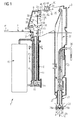
- FIG. 1 With reference to Figures 1 to 5 , there is shown a packaging machine 1 for continuously producing aseptic sealed packages of a pourable food product from a web of packaging material 2 (hereafter referred to simply as "web 2").
- the packaging machine 1 comprises a sterilizing unit 3, to which the web 2 is fed off a reel (not shown) along a path P1.
- the sterilizing unit 3 comprises a transition chamber 7, into which the web 2 is first fed, a sterilizing bath 8 containing a liquid sterilizing agent, e.g. a 30% solution of hydrogen peroxide (H2O2) and water, through which the web 2 is advanced, and an aseptic chamber 9, in which the web 2 is dried, as explained in detail below.
- a liquid sterilizing agent e.g. a 30% solution of hydrogen peroxide (H2O2) and water
- the bath 8 is substantially defined by a U-shaped conduit filled, in use, with the sterilizing agent to a predetermined level.
- the U-shaped conduit is defined by an inlet branch 10 and by an outlet branch 11 having, respectively, a first top opening 12 and a second top opening 13, which define the inlet and outlet of the web 2 into and out of the bath 8, and communicate respectively with the transition chamber 7 and the aseptic chamber 9.
- the inlet branch 10 and the outlet branch 11 are connected at the bottom by a bottom portion 14 of the bath 8 housing a horizontal-axis guide roller 15, on which the web 2 is partially wound.
- the web 2 therefore describes a U-shaped path P2 of such a length as to keep the packaging material long enough inside the sterilizing agent.
- the bath 8 is connected to a peroxide control circuit 16 - known and therefore not shown in detail - and is maintained, in use, at a controlled temperature, e.g. of around 70°C - 80°C.
- the aseptic chamber 9 is separated from the transition chamber 7 by a partition 17 and has an inlet for web 2, coincident with the outlet (second top opening 13) of the bath 8.
- the aseptic chamber 9 comprises a top portion 20, housing drying means 21 for removing residual sterilizing agent from the web 2, and a bottom portion 22 extending vertically and parallel to the bath 8, and in which the web 2 is folded longitudinally into a cylinder and sealed longitudinally to form a continuous cylindrical tube 23 having a vertical axis A.
- the aseptic chamber 9 is maintained slightly above ambient pressure, so that any leakage through the seals occurs outwards as opposed to inwards of the chamber.
- the web 2 describes first a vertical path P3 extending on the prolongation of the vertical portion of path P2 in the outlet branch 11 and is then diverted by a first roller 24 and a second roller 25 onto a substantially horizontal path P4 and onto a vertical path P5 in the bottom portion 22, parallel to axis A of the tube 23.
- the tube 23, formed downstream from the second roller 25, is filled continuously with the food product for packaging by means of a fill conduit 26, and comes out downwards through a bottom opening 27 of the aseptic chamber 9, of which it substantially forms an extension.
- the packaging machine 1 comprises a known transverse form-and-seal unit 28, not shown in detail, in which the tube 23 is gripped between pairs of jaws 28a, which seal the tube 23 transversely to form aseptic pillow packs 29 eventually formed by known cutting and folding operations into individual packages.
- the drying means 21 comprise two idle squeeze rollers 30 having parallel horizontal axes, located close to the inlet of the aseptic chamber 9, on opposite sides of web 2, and at least one of which is covered with relatively soft material.
- the squeeze rollers 30 exert pressure on respective opposite faces of the web 2 to squeeze the drops of sterilizing agent out and back into the bath 8.
- drying means 21 also comprise two so-called "air knives" 35 located on opposite sides of the web 2, downstream from the squeeze rollers 30 with reference to path P3 and therefore above the squeeze rollers 30.
- Each air knife 35 comprises a nozzle 36 for directing a stream of air downwards (i.e. towards the bath 8) and on a respective face of the web 2 and, and a respective guide wall 38 that guides the respective stream of air, in use, in a direction substantially parallel to the web 2 but opposite to the travelling direction thereof.
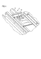
- the sterilizing unit 3 further comprises a UV sterilizing device 40 positioned downstream of the sterilizing bath 8 and arranged to further sterilize the web 2.
- the UV sterilizing device 40 is positioned along path P4.
- the UV sterilizing device 40 comprises a casing 41 extending crosswise to the web 2 and open on the side of the web 2 so as to form a window 42.
- the UV sterilizing device 40 also comprises a UV radiation source 43 housed longitudinally in the casing 41, which is provided with a reflecting element 44.
- the UV radiation source 6 emits UV radiation, for example of a wavelength of 222 nm.
- the window 42 faces an aperture 45 of an upper wall 46 of the aseptic chamber 9 so that the UV radiation is directed - through the window 42 and the aperture 45 - onto the web 2.
- the sterilizing unit 3 further comprises a detecting device 50 for detecting the amount of UV radiation emitted by the UV sterilizing device 40 that interacts with the web 2.
- the detecting 50 device in case it detects an amount of UV radiation that is below a certain threshold - generates an error signal and possibly stops the packaging machine 1, since the level of UV radiation may be not sufficient to assure a proper sterilization of the web 2.
- the low amount of UV radiation may be due to a defect, or a problem, in the UV sterilizing device.
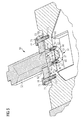
- the detecting device 50 is positioned in a lateral wall 51 of the aseptic chamber.
- the detecting device 50 comprises a detecting sensor 52, for example a radiometer, for detecting UV radiation and a protecting screen 53 transparent to UV radiation for protecting a lens 54 of the detecting sensor 52.
- the protecting screen 53 may be made of a polymer material.
- the polymer material may be of any type, provided it is transparent to UV radiation (T ⁇ 80%) and resistant to the UV radiation.
- the polymer material may, for example, be in the polyolefin group, such as PE or PP.
- the material is a fluorinated polymer, or a completely fluorinated polymer in the perfluoroalkoxy (PFA) class.
- the material is an MFA, e.g. the MFA available on the market under the trade name HYFLON® MFA.
- the detecting device 50 comprises an extension arrangement 55 provided with an elongated element 56 interposed between the detecting sensor 52 and the protecting screen 53 and defining a through channel 57.
- the channel 57 has a first end 58 covered by the protecting screen 53 and a second end 59 facing the lens 54.
- the extension arrangement 55 also comprises a supporting body 60 provided with a through bore 61 that receives a portion 62 of the detecting sensor 52 supporting the lens 54, or comprising the lens 54.
- the bore 61 is connected with the channel 57.
- the channel 57 and the bore 61 are substantially coaxial, the bore 61 having a diameter that is greater than a diameter of the channel 57.
- the elongated element 56 is distinct from the supporting body 60 and comprises a flange 63 fixed to the supporting body 60.
- the protecting screen 53 is distinct from the elongated element 56 and is fixed to the elongated element 56 at the first end 58.
- the detecting device 50 comprises a fixing frame 64 for fixing the protecting screen 53 to the elongated element 56 and having a peripheral body 65 defining a window element 66.
- the fixing frame 64 and the protecting screen 53 are connected to the elongated element 56 by means of screws 67.
- the lateral wall 51 has a first side 68 delimiting the inside of the aseptic chamber 9 and a second side 69, opposite to the first side 68, delimiting the outside of the aseptic chamber 9.
- a hole 70 extends through the lateral wall 51 from the first side 68 to the second side 69, i.e. between the outside of the aseptic chamber 9 and the inside of the aseptic chamber 9.
- the elongated element 56 is received in the hole 70.
- first end 58 is close to the first wall 68 and the second end 59 is close to the second wall 59.
- first end 58 is aligned with the first wall 68 and the second end 59 is aligned with the second wall 59.
- the flange 63 abuts against the second wall 69.
- the elongated element 56 has an axial length L that is substantially equal to a width W of the lateral wall 51.
- the protecting screen 53 is arranged inside the aseptic chamber 9. In particular, the protecting screen 53 abuts against the first side 68.
- the supporting body 60 has first holes 71 and the flange 63 has second holes 72.
- the lateral wall 51 has threaded holes 73.
- the supporting body 60 and the elongated element 56 are fixed to the lateral wall 51 by means of screw elements 74 passing through the first holes 71 and the second holes 72 and mating with the threaded holes 73.
- the supporting body 60 is made of heat insulating material, for example plastics, to protect the detecting sensor 52 from the heat generated by the hot air in the sterilizing unit 3.
- the web 2 is fed through the bath 8.
- the web 2 On entering the aseptic chamber 9 the web 2 is fed through the squeeze rollers 30, which squeeze the drops of residual sterilizing agent out and back into the bath 8.
- the web 2 enters the air knives 35 and is swept by sterile-air streams ejected from the nozzles 36 and guided along the opposite faces of the web 2 by the guide walls 38.
- the web 2 Downstream of the the air knives 35, the web 2 is diverted by the roller 24 along path P4 and is further sterilized by the UV radiation generated by the UV sterilization device 40.
- the web is diverted by roller 25 along path P5 and is then folded into a cylinder and sealed longitudinally to form the tube 23, which is filled continuously with the pourable food product from the conduit 26, and is gripped and sealed transversely by jaws 28a to form a succession of pillow packs 29.
- the protecting screen 53 is placed inside the aseptic chamber 9. In this way, the protecting screen 53 is continuously cleaned, or swept, by the stream of hot hair flowing in the aseptic chamber 9, as shown by the arrows F in Figure 4 . In this way, droplets of condensed vapor are prevented from accumulating on the protecting screen 53. In any case, the droplets of condensed vapor - which may have formed on the protecting screen 53 - are immediately removed by the stream of hot air. In this way, the droplets of condensed water do not adversely affect the detecting capability of the detecting sensor 52. Therefore, no false alarm - due to a wrong detection caused by the droplets of condensed vapor - is generated by the detecting device 50.
Landscapes
- Health & Medical Sciences (AREA)
- Physics & Mathematics (AREA)
- General Physics & Mathematics (AREA)
- Spectroscopy & Molecular Physics (AREA)
- General Health & Medical Sciences (AREA)
- Animal Behavior & Ethology (AREA)
- Life Sciences & Earth Sciences (AREA)
- Epidemiology (AREA)
- Public Health (AREA)
- Veterinary Medicine (AREA)
- Engineering & Computer Science (AREA)
- Mechanical Engineering (AREA)
- Toxicology (AREA)
- Apparatus For Disinfection Or Sterilisation (AREA)
- Containers And Plastic Fillers For Packaging (AREA)
Priority Applications (1)
| Application Number | Priority Date | Filing Date | Title |
|---|---|---|---|
| EP14189314.9A EP3009362A1 (fr) | 2014-10-17 | 2014-10-17 | Dispositif de détection pour détecter un rayonnement UV |
Applications Claiming Priority (1)
| Application Number | Priority Date | Filing Date | Title |
|---|---|---|---|
| EP14189314.9A EP3009362A1 (fr) | 2014-10-17 | 2014-10-17 | Dispositif de détection pour détecter un rayonnement UV |
Publications (1)
| Publication Number | Publication Date |
|---|---|
| EP3009362A1 true EP3009362A1 (fr) | 2016-04-20 |
Family
ID=51730408
Family Applications (1)
| Application Number | Title | Priority Date | Filing Date |
|---|---|---|---|
| EP14189314.9A Withdrawn EP3009362A1 (fr) | 2014-10-17 | 2014-10-17 | Dispositif de détection pour détecter un rayonnement UV |
Country Status (1)
| Country | Link |
|---|---|
| EP (1) | EP3009362A1 (fr) |
Cited By (4)
| Publication number | Priority date | Publication date | Assignee | Title |
|---|---|---|---|---|
| CN107224596A (zh) * | 2017-04-28 | 2017-10-03 | 广东久量股份有限公司 | 一种紫外线人体感应杀菌灯 |
| WO2019025979A1 (fr) * | 2017-07-31 | 2019-02-07 | Liquibox Spain Sl | Machine et procédé de préparation de poches souples stérilisées pour l'emballage de produits |
| CN112004561A (zh) * | 2018-04-03 | 2020-11-27 | 利乐拉瓦尔集团及财务有限公司 | 灭菌设备、具有灭菌设备的包装机以及灭菌方法 |
| CN114555478A (zh) * | 2019-11-29 | 2022-05-27 | 京洛株式会社 | 制袋填充方法以及制袋填充系统 |
Citations (6)
| Publication number | Priority date | Publication date | Assignee | Title |
|---|---|---|---|---|
| US4396582A (en) * | 1980-03-31 | 1983-08-02 | Dai Nippon Insatsu Kabushiki Kaisha | Method and apparatus for sterilizing food packages or the like |
| DE19903259C1 (de) * | 1999-01-28 | 2000-07-13 | Hassia Verpackung Ag | Vorrichtung zum Entkeimen von Packstoffbahnen |
| US20020104290A1 (en) * | 2001-02-03 | 2002-08-08 | Hassia Verpackungsmaschinen Gmbh | Process and machine for dividing a multi-layered web utilized in aseptic packaging into a plurality of individual webs of equal width |
| US6592816B1 (en) * | 1999-03-01 | 2003-07-15 | Johnson & Johnson Vision Care, Inc. | Sterilization system |
| US20080286424A1 (en) * | 2005-02-10 | 2008-11-20 | Wyeth | Apparatus and Method For Radiation Processing of Fluent Food Products |
| WO2014086675A2 (fr) * | 2012-12-03 | 2014-06-12 | Tetra Laval Holdings & Finance S.A. | Dispositif et procédé d'irradiation de récipients de conditionnement avec un faisceau d'électrons |
-
2014
- 2014-10-17 EP EP14189314.9A patent/EP3009362A1/fr not_active Withdrawn
Patent Citations (6)
| Publication number | Priority date | Publication date | Assignee | Title |
|---|---|---|---|---|
| US4396582A (en) * | 1980-03-31 | 1983-08-02 | Dai Nippon Insatsu Kabushiki Kaisha | Method and apparatus for sterilizing food packages or the like |
| DE19903259C1 (de) * | 1999-01-28 | 2000-07-13 | Hassia Verpackung Ag | Vorrichtung zum Entkeimen von Packstoffbahnen |
| US6592816B1 (en) * | 1999-03-01 | 2003-07-15 | Johnson & Johnson Vision Care, Inc. | Sterilization system |
| US20020104290A1 (en) * | 2001-02-03 | 2002-08-08 | Hassia Verpackungsmaschinen Gmbh | Process and machine for dividing a multi-layered web utilized in aseptic packaging into a plurality of individual webs of equal width |
| US20080286424A1 (en) * | 2005-02-10 | 2008-11-20 | Wyeth | Apparatus and Method For Radiation Processing of Fluent Food Products |
| WO2014086675A2 (fr) * | 2012-12-03 | 2014-06-12 | Tetra Laval Holdings & Finance S.A. | Dispositif et procédé d'irradiation de récipients de conditionnement avec un faisceau d'électrons |
Cited By (8)
| Publication number | Priority date | Publication date | Assignee | Title |
|---|---|---|---|---|
| CN107224596A (zh) * | 2017-04-28 | 2017-10-03 | 广东久量股份有限公司 | 一种紫外线人体感应杀菌灯 |
| WO2019025979A1 (fr) * | 2017-07-31 | 2019-02-07 | Liquibox Spain Sl | Machine et procédé de préparation de poches souples stérilisées pour l'emballage de produits |
| CN111107883A (zh) * | 2017-07-31 | 2020-05-05 | 利奎保克斯西班牙公司 | 用于制备用于包装产品的灭菌柔性袋的机器和工艺 |
| CN112004561A (zh) * | 2018-04-03 | 2020-11-27 | 利乐拉瓦尔集团及财务有限公司 | 灭菌设备、具有灭菌设备的包装机以及灭菌方法 |
| CN112004561B (zh) * | 2018-04-03 | 2021-10-12 | 利乐拉瓦尔集团及财务有限公司 | 灭菌设备、具有灭菌设备的包装机以及灭菌方法 |
| US11390409B2 (en) | 2018-04-03 | 2022-07-19 | Tetra Laval Holdings & Finance S.A. | Sterilization apparatus, packaging machine having a sterilization apparatus and a method for sterilizing |
| CN114555478A (zh) * | 2019-11-29 | 2022-05-27 | 京洛株式会社 | 制袋填充方法以及制袋填充系统 |
| CN114555478B (zh) * | 2019-11-29 | 2024-01-26 | 京洛株式会社 | 制袋填充方法以及制袋填充系统 |
Similar Documents
| Publication | Publication Date | Title |
|---|---|---|
| RU2413663C2 (ru) | Модуль стерилизации упаковочного материала для устройства упаковки разливаемого пищевого продукта | |
| US10077127B2 (en) | Method and arrangement for treating bags to be filled with a product prior to filling the bags with a product | |
| EP3009362A1 (fr) | Dispositif de détection pour détecter un rayonnement UV | |
| KR100958236B1 (ko) | 유동성 식품을 포장하는 기계상에서 웹-피드된 재료를살균하는 유닛 | |
| JP2000335525A (ja) | ストリップ包装材料を殺菌するユニット | |
| US11383869B2 (en) | Packaging machine and method for producing sealed packages | |
| KR20040086335A (ko) | 유출 가능한 식료품 포장용 기계상의 웹 공급 재료를멸균하는 장치 | |
| US20110203221A1 (en) | Apparatus and method for detecting the position of application of a sealing strip onto a web of packaging material for food products | |
| JP2000355310A (ja) | ストリップ包装材料を殺菌するユニット | |
| EP3427757A2 (fr) | Appareil de stérilisation permettant de stériliser une bande de matériau d'emballage et procédé de stérilisation | |
| JP7402815B2 (ja) | 殺菌装置、殺菌装置を有するパッケージ機、及び殺菌するための方法 | |
| JP4034920B2 (ja) | 妨害材料が存在する試料中の物質濃度の決定方法および装置 | |
| US9408932B2 (en) | Unit for sterilizing a web of packaging material for a machine for packaging pourable food products | |
| CN208453350U (zh) | 从包装材料的卷材中去除灭菌剂的干燥单元和干燥构件 | |
| JP2009083857A (ja) | 密封袋の製造管理方法及び装置 | |
| US20020197184A1 (en) | System and method for sterilizing a continuously moving web for forming, filling, and sealing flexible packages | |
| US7145158B2 (en) | Device for treating a packaging material by means of UV radiation | |
| JP2024505771A (ja) | パッケージ製造機及びパッケージ製造機用の無菌チャンバ | |
| EP4368521A1 (fr) | Machine d'emballage pour produire des emballages scellés d'un produit pouvant être versé à partir d'une bande de matériau d'emballage | |
| US20070176118A1 (en) | Apparatus and method for sterilizing a spout assembly of a container | |
| WO2024099924A1 (fr) | Appareil de stérilisation, machine d'emballage présentant un appareil de stérilisation et procédé de stérilisation | |
| EP4219321A1 (fr) | Machine d'emballage et procédé de formation d'emballages | |
| WO2024099925A1 (fr) | Machine d'emballage permettant de produire des emballages scellés d'un produit fluide à partir d'une bande de matériau d'emballage | |
| AU2002322018A1 (en) | Apparatus for sterilizing web material in a form-fill-seal machine |
Legal Events
| Date | Code | Title | Description |
|---|---|---|---|
| PUAI | Public reference made under article 153(3) epc to a published international application that has entered the european phase |
Free format text: ORIGINAL CODE: 0009012 |
|
| AK | Designated contracting states |
Kind code of ref document: A1 Designated state(s): AL AT BE BG CH CY CZ DE DK EE ES FI FR GB GR HR HU IE IS IT LI LT LU LV MC MK MT NL NO PL PT RO RS SE SI SK SM TR |
|
| AX | Request for extension of the european patent |
Extension state: BA ME |
|
| 17P | Request for examination filed |
Effective date: 20161020 |
|
| RBV | Designated contracting states (corrected) |
Designated state(s): AL AT BE BG CH CY CZ DE DK EE ES FI FR GB GR HR HU IE IS IT LI LT LU LV MC MK MT NL NO PL PT RO RS SE SI SK SM TR |
|
| 17Q | First examination report despatched |
Effective date: 20161220 |
|
| STAA | Information on the status of an ep patent application or granted ep patent |
Free format text: STATUS: THE APPLICATION IS DEEMED TO BE WITHDRAWN |
|
| 18D | Application deemed to be withdrawn |
Effective date: 20170503 |