EP3007803B1 - Procédé de décarbonatation d'un gaz hydrocarboné - Google Patents
Procédé de décarbonatation d'un gaz hydrocarboné Download PDFInfo
- Publication number
- EP3007803B1 EP3007803B1 EP14811587.6A EP14811587A EP3007803B1 EP 3007803 B1 EP3007803 B1 EP 3007803B1 EP 14811587 A EP14811587 A EP 14811587A EP 3007803 B1 EP3007803 B1 EP 3007803B1
- Authority
- EP
- European Patent Office
- Prior art keywords
- absorbent solution
- amino
- methyl
- gas
- propanol
- Prior art date
- Legal status (The legal status is an assumption and is not a legal conclusion. Google has not performed a legal analysis and makes no representation as to the accuracy of the status listed.)
- Active
Links
Images

Classifications
-
- B—PERFORMING OPERATIONS; TRANSPORTING
- B01—PHYSICAL OR CHEMICAL PROCESSES OR APPARATUS IN GENERAL
- B01D—SEPARATION
- B01D53/00—Separation of gases or vapours; Recovering vapours of volatile solvents from gases; Chemical or biological purification of waste gases, e.g. engine exhaust gases, smoke, fumes, flue gases, aerosols
- B01D53/14—Separation of gases or vapours; Recovering vapours of volatile solvents from gases; Chemical or biological purification of waste gases, e.g. engine exhaust gases, smoke, fumes, flue gases, aerosols by absorption
- B01D53/1418—Recovery of products
-
- B—PERFORMING OPERATIONS; TRANSPORTING
- B01—PHYSICAL OR CHEMICAL PROCESSES OR APPARATUS IN GENERAL
- B01D—SEPARATION
- B01D53/00—Separation of gases or vapours; Recovering vapours of volatile solvents from gases; Chemical or biological purification of waste gases, e.g. engine exhaust gases, smoke, fumes, flue gases, aerosols
- B01D53/14—Separation of gases or vapours; Recovering vapours of volatile solvents from gases; Chemical or biological purification of waste gases, e.g. engine exhaust gases, smoke, fumes, flue gases, aerosols by absorption
- B01D53/1425—Regeneration of liquid absorbents
-
- B—PERFORMING OPERATIONS; TRANSPORTING
- B01—PHYSICAL OR CHEMICAL PROCESSES OR APPARATUS IN GENERAL
- B01D—SEPARATION
- B01D53/00—Separation of gases or vapours; Recovering vapours of volatile solvents from gases; Chemical or biological purification of waste gases, e.g. engine exhaust gases, smoke, fumes, flue gases, aerosols
- B01D53/14—Separation of gases or vapours; Recovering vapours of volatile solvents from gases; Chemical or biological purification of waste gases, e.g. engine exhaust gases, smoke, fumes, flue gases, aerosols by absorption
- B01D53/1456—Removing acid components
- B01D53/1475—Removing carbon dioxide
-
- B—PERFORMING OPERATIONS; TRANSPORTING
- B01—PHYSICAL OR CHEMICAL PROCESSES OR APPARATUS IN GENERAL
- B01D—SEPARATION
- B01D53/00—Separation of gases or vapours; Recovering vapours of volatile solvents from gases; Chemical or biological purification of waste gases, e.g. engine exhaust gases, smoke, fumes, flue gases, aerosols
- B01D53/14—Separation of gases or vapours; Recovering vapours of volatile solvents from gases; Chemical or biological purification of waste gases, e.g. engine exhaust gases, smoke, fumes, flue gases, aerosols by absorption
- B01D53/1493—Selection of liquid materials for use as absorbents
-
- C—CHEMISTRY; METALLURGY
- C10—PETROLEUM, GAS OR COKE INDUSTRIES; TECHNICAL GASES CONTAINING CARBON MONOXIDE; FUELS; LUBRICANTS; PEAT
- C10L—FUELS NOT OTHERWISE PROVIDED FOR; NATURAL GAS; SYNTHETIC NATURAL GAS OBTAINED BY PROCESSES NOT COVERED BY SUBCLASSES C10G OR C10K; LIQUIFIED PETROLEUM GAS; USE OF ADDITIVES TO FUELS OR FIRES; FIRE-LIGHTERS
- C10L3/00—Gaseous fuels; Natural gas; Synthetic natural gas obtained by processes not covered by subclass C10G, C10K; Liquefied petroleum gas
- C10L3/06—Natural gas; Synthetic natural gas obtained by processes not covered by C10G, C10K3/02 or C10K3/04
- C10L3/10—Working-up natural gas or synthetic natural gas
- C10L3/101—Removal of contaminants
-
- C—CHEMISTRY; METALLURGY
- C10—PETROLEUM, GAS OR COKE INDUSTRIES; TECHNICAL GASES CONTAINING CARBON MONOXIDE; FUELS; LUBRICANTS; PEAT
- C10L—FUELS NOT OTHERWISE PROVIDED FOR; NATURAL GAS; SYNTHETIC NATURAL GAS OBTAINED BY PROCESSES NOT COVERED BY SUBCLASSES C10G OR C10K; LIQUIFIED PETROLEUM GAS; USE OF ADDITIVES TO FUELS OR FIRES; FIRE-LIGHTERS
- C10L3/00—Gaseous fuels; Natural gas; Synthetic natural gas obtained by processes not covered by subclass C10G, C10K; Liquefied petroleum gas
- C10L3/06—Natural gas; Synthetic natural gas obtained by processes not covered by C10G, C10K3/02 or C10K3/04
- C10L3/10—Working-up natural gas or synthetic natural gas
- C10L3/101—Removal of contaminants
- C10L3/102—Removal of contaminants of acid contaminants
- C10L3/104—Carbon dioxide
-
- E—FIXED CONSTRUCTIONS
- E21—EARTH OR ROCK DRILLING; MINING
- E21B—EARTH OR ROCK DRILLING; OBTAINING OIL, GAS, WATER, SOLUBLE OR MELTABLE MATERIALS OR A SLURRY OF MINERALS FROM WELLS
- E21B43/00—Methods or apparatus for obtaining oil, gas, water, soluble or meltable materials or a slurry of minerals from wells
- E21B43/16—Enhanced recovery methods for obtaining hydrocarbons
- E21B43/164—Injecting CO2 or carbonated water
-
- E—FIXED CONSTRUCTIONS
- E21—EARTH OR ROCK DRILLING; MINING
- E21B—EARTH OR ROCK DRILLING; OBTAINING OIL, GAS, WATER, SOLUBLE OR MELTABLE MATERIALS OR A SLURRY OF MINERALS FROM WELLS
- E21B43/00—Methods or apparatus for obtaining oil, gas, water, soluble or meltable materials or a slurry of minerals from wells
- E21B43/34—Arrangements for separating materials produced by the well
- E21B43/40—Separation associated with re-injection of separated materials
-
- B—PERFORMING OPERATIONS; TRANSPORTING
- B01—PHYSICAL OR CHEMICAL PROCESSES OR APPARATUS IN GENERAL
- B01D—SEPARATION
- B01D2252/00—Absorbents, i.e. solvents and liquid materials for gas absorption
- B01D2252/20—Organic absorbents
- B01D2252/204—Amines
- B01D2252/20478—Alkanolamines
- B01D2252/20489—Alkanolamines with two or more hydroxyl groups
-
- C—CHEMISTRY; METALLURGY
- C10—PETROLEUM, GAS OR COKE INDUSTRIES; TECHNICAL GASES CONTAINING CARBON MONOXIDE; FUELS; LUBRICANTS; PEAT
- C10L—FUELS NOT OTHERWISE PROVIDED FOR; NATURAL GAS; SYNTHETIC NATURAL GAS OBTAINED BY PROCESSES NOT COVERED BY SUBCLASSES C10G OR C10K; LIQUIFIED PETROLEUM GAS; USE OF ADDITIVES TO FUELS OR FIRES; FIRE-LIGHTERS
- C10L2290/00—Fuel preparation or upgrading, processes or apparatus therefore, comprising specific process steps or apparatus units
- C10L2290/06—Heat exchange, direct or indirect
-
- C—CHEMISTRY; METALLURGY
- C10—PETROLEUM, GAS OR COKE INDUSTRIES; TECHNICAL GASES CONTAINING CARBON MONOXIDE; FUELS; LUBRICANTS; PEAT
- C10L—FUELS NOT OTHERWISE PROVIDED FOR; NATURAL GAS; SYNTHETIC NATURAL GAS OBTAINED BY PROCESSES NOT COVERED BY SUBCLASSES C10G OR C10K; LIQUIFIED PETROLEUM GAS; USE OF ADDITIVES TO FUELS OR FIRES; FIRE-LIGHTERS
- C10L2290/00—Fuel preparation or upgrading, processes or apparatus therefore, comprising specific process steps or apparatus units
- C10L2290/12—Regeneration of a solvent, catalyst, adsorbent or any other component used to treat or prepare a fuel
-
- C—CHEMISTRY; METALLURGY
- C10—PETROLEUM, GAS OR COKE INDUSTRIES; TECHNICAL GASES CONTAINING CARBON MONOXIDE; FUELS; LUBRICANTS; PEAT
- C10L—FUELS NOT OTHERWISE PROVIDED FOR; NATURAL GAS; SYNTHETIC NATURAL GAS OBTAINED BY PROCESSES NOT COVERED BY SUBCLASSES C10G OR C10K; LIQUIFIED PETROLEUM GAS; USE OF ADDITIVES TO FUELS OR FIRES; FIRE-LIGHTERS
- C10L2290/00—Fuel preparation or upgrading, processes or apparatus therefore, comprising specific process steps or apparatus units
- C10L2290/54—Specific separation steps for separating fractions, components or impurities during preparation or upgrading of a fuel
- C10L2290/541—Absorption of impurities during preparation or upgrading of a fuel
-
- Y—GENERAL TAGGING OF NEW TECHNOLOGICAL DEVELOPMENTS; GENERAL TAGGING OF CROSS-SECTIONAL TECHNOLOGIES SPANNING OVER SEVERAL SECTIONS OF THE IPC; TECHNICAL SUBJECTS COVERED BY FORMER USPC CROSS-REFERENCE ART COLLECTIONS [XRACs] AND DIGESTS
- Y02—TECHNOLOGIES OR APPLICATIONS FOR MITIGATION OR ADAPTATION AGAINST CLIMATE CHANGE
- Y02C—CAPTURE, STORAGE, SEQUESTRATION OR DISPOSAL OF GREENHOUSE GASES [GHG]
- Y02C20/00—Capture or disposal of greenhouse gases
- Y02C20/40—Capture or disposal of greenhouse gases of CO2
Definitions
- the present invention relates to the field of decarbonation by washing with a solvent a hydrocarbon gas, for example a natural gas.
- the invention provides a method for separating, during regeneration, most of the hydrocarbons co-absorbed by the solvent from most of the acid gases absorbed by the solvent. The method thus makes it possible to control the hydrocarbon content at the top of the regenerator.
- thermally regenerable liquid solvents to extract the acidic compounds contained in a gas, in particular in a natural gas.
- solvents include aqueous solutions of amines, and some physical solvents such as sulfolane, methanol, N-formyl morpholine, acetyl morpholine, propylene carbonate.
- These processes generally comprise a step of extracting the CO 2 contained in the gas to be treated by contacting this gas with the regenerated solvent, in an absorber operating at the pressure of the gas to be treated, followed by a regeneration step thermal, generally operating at a pressure slightly above atmospheric pressure, generally between 1 and 5 bar, preferably between 1.5 and 3 bar.
- This thermal regeneration is generally carried out in a column equipped at the bottom of a reboiler and at the top of a condenser for cooling the acidic compounds released by the regeneration and to recycle the condensates at the top of the regenerator as reflux.
- the solvent rich in acid gases obtained in the bottom of the The absorber may contain significant amounts of dissolved hydrocarbons. It is then common to use a step of releasing these vaporized dissolved hydrocarbons by simply relaxing the solvent rich in acidic gases. This expansion is carried out at a pressure intermediate between that of the raw gas to be treated and that of the regeneration thermal step, typically of the order of 5 to 15 bars. Thus, a CO 2 -rich solvent is separated, a gas containing the lightest and predominantly dissolved hydrocarbons. volumes, which can be used as flue gas.
- This gas is sometimes washed with a stream of regenerated solvent from the thermal step so as to reabsorb the acidic compounds released during the expansion.
- This washing of the gas released by the expansion is generally carried out in a column placed directly on the separation tank between the gas and the expanded liquid.
- the solvent thus loaded with acid compounds is directly mixed with the expanded solvent and sent to the thermal regeneration step.
- a heat exchange step is generally carried out between the rich solvent, after expansion, and the regenerated solvent obtained hot at the bottom of the regeneration column.
- Regeneration of these solvents produces a gaseous effluent rich in acidic compounds.
- the raw gas contains significant amounts of heavy hydrocarbons (for example, a few hundred ppmV)
- these gases are found in significant amounts in the acid gas at the top of the regenerator.
- the step of expanding the solvent rich in acid gas obtained in the bottom of the absorber if it makes it possible to release most of the light hydrocarbons (methane, ethane, etc.) dissolved in the solvent at the bottom of the absorber, does not allow to extract most of the heavier compounds. It is then common to obtain an acid gas at the top of the regenerator that can contain several hundred ppmv of hydrocarbons.
- VOC Volatile Organic Compounds
- the VOCs consist of the following hydrocarbon compounds: Linear alkanes (methane is sometimes excluded); cycloalkanes, aromatics (benzene, toluene, ethyl benzene and xylenes). It is then necessary to provide a step of post-treatment of the acid gas, such as an incineration which can be expensive in equipment and very energy-intensive (consumption of combustion gases).
- the present invention proposes a simple and inexpensive method, because requiring only a small number of additional equipment, to separate, during the regeneration, the majority of the hydrocarbons co-absorbed by the solvent of the majority of the acid gases absorbed by the solvent.
- the method achieves this by using a flash system BP (low pressure), thus controlling the hydrocarbon content at the top of the regenerator.
- the pressure and the temperature can be chosen so that the gaseous fraction comprises at least 70% of the hydrocarbons contained in the absorbent solution loaded with CO 2 and less than 30% of CO 2 contained in the absorbent solution loaded with CO 2 .
- the temperature may be between that of the absorbent solution loaded with CO 2 obtained after step a) and that of the regenerated absorbent solution obtained after step c), and the pressure may be greater than atmospheric pressure.
- the temperature may for example be between 50 ° C and 140 ° C, and the pressure between 1.5 and 6 bar.
- At least a part of the regenerated absorbent solution obtained in step c) can be recycled in step a) as an absorbent solution.
- the absorbent solution loaded with CO 2 is expanded at a pressure P2 between the pressure used in step b) and a pressure used in step a), and at a temperature of substantially identical to that of the absorbent solution loaded with CO 2 obtained after step a).
- the pressure P2 may be between 5 and 15 bar.
- the absorbent solution may comprise an amine or a mixture of amines in solution in water.
- the amine may be selected from the group consisting of primary amines, secondary amines, sterically hindered secondary amines, tertiary amines and mixtures of tertiary amines and primary or secondary amines.
- the primary amine may be chosen, alone or as a mixture, from monoethanolamine (MEA), aminoethylethanolamine (AEEA), diglycolamine, 2-amino-2-methyl-1-propanol and its non-N-substituted derivatives.
- MEA monoethanolamine
- AEEA aminoethylethanolamine
- diglycolamine 2-amino-2-methyl-1-propanol and its non-N-substituted derivatives.
- the secondary amine may be chosen, alone or as a mixture, from diethanolamine (DEA), diisopropanolamine (DIPA), piperazine and its derivatives in which at least one nitrogen atom is not substituted, morpholine and its derivatives. non-substituted derivatives, piperidine and its non-N-substituted derivatives, N- (2'-hydroxyethyl) -2-amino-2-methyl-1-propanol, N- (2'-hydroxypropyl) -2-amino- 2-methyl-1-propanol, N- (2'-hydroxybutyl) -2-amino-2-methyl-1-propanol.
- DEA diethanolamine
- DIPA diisopropanolamine
- the tertiary amine may be chosen, alone or as a mixture, from methyldiethanolamine (MDEA), triethanolamine (TEA), ethyldiethanolamine, diethylethanolamine, dimethylethanolamine, 1-methyl-4- (3-dimethylaminopropyl) - piperazine, 1-ethyl-4- (diethylaminoethyl), 1-methyl-4-hydroxy-piperidine, 1-methyl-2-hydroxymethyl-piperidine, 1,2-bis (2-dimethylaminoethoxy) -ethane, Bis (dimethylamino-3-propyl) ether, bis (diethylamino-3-propyl) ether, (dimethylamino-2-ethyl) - (dimethylamino-3-propyl) -ether, (diethylamino-2-ethyl) - (dimethylamino-3-propyl) -ether, (dimethylamino-2-ethy
- the hindered secondary amine may be chosen, alone or as a mixture, from N- (2'-hydroxyethyl) -2-amino-2-methyl-1-propanol, N- (2'-hydroxypropyl) -2-amino -2-methyl-1-propanol, N- (2'-hydroxybutyl) -2-amino-2-methyl-1-propanol.
- the mixtures of tertiary amines and primary or secondary amines, the primary or secondary amines may be chosen from the group comprising monoethanolamine, diethanolamine, n-butylethanolamine, aminoethylethanolamine, diglycolamine, piperazine, Methylpiperazine, 2-methylpiperazine, N- (2-hydroxyethyl) piperazine, N- (2-aminoethyl) piperazine, Morpholine, 3- (methylamino) propylamine, 1,6-hexanediamine and all its various derivatives N -alkylated such for example the N, N'-dimethyl-1,6-hexanediamine, N-methyl-1,6-hexanediamine or N, N ', N'-trimethyl-1,6-hexanediamine.
- the absorbent solution may be selected from the group consisting of sulfolane, methanol, N-formyl morpholine, acetyl morpholine, propylene carbonate, dimethyl ether polyethylene glycol or N-methyl pyrrolidone or a mixture of amine with a physical solvent and water.
- the gas can be a natural gas.
- the gas may comprise at least 50 ppmv of hydrocarbons. It may comprise less than 100 ppmv of H 2 S.
- the invention also relates to a method in which the CO 2 -rich gaseous effluent obtained at the end of step c) is injected into an underground medium in a process for the enhanced recovery of hydrocarbons.
- the present invention proposes a simple and inexpensive method because requiring only a small number of additional equipment, to separate most of the hydrocarbons co-absorbed by the solvent from the major part of the acid gases absorbed by the solvent and so check the hydrocarbon content at the top of the regenerator.
- At least a portion of the regenerated absorbent solution obtained in step c) is recycled in step a) as an absorbent solution.
- the absorbent solution is preferably heated by exchanging with a process fluid through a heat exchanger, but any other means of heating to obtain a suitable temperature can be used.
- the absorbent solution thus heated undergoes expansion at a pressure and a temperature determined so as to release a gaseous fraction comprising predominantly hydrocarbons and to obtain a hydrocarbon-depleted absorbent solution.
- the pressure and temperature conditions are optimized so that the gaseous fraction comprises at least 50% of the hydrocarbons contained in the absorbent solution loaded with acid gases and at most 35% of the acid gases contained in the charged absorbent solution.
- the gas to be treated is admitted via line 1 at the bottom of an absorber 2.
- the gas from which the acid gases absorbed by the solvent is extracted is extracted at the head of the absorber by the line 26, as well as the fractions co-absorbed compounds, especially hydrocarbons.
- This absorber generally operates at temperatures close to or slightly above ambient temperature, typically between 20 and 100 ° C, preferably between 30 and 90 ° C, and at pressures typically between 10 and 200 bar, preferably between 20 and 100 ° C. and 100 bars.
- the gas arriving via line 1 may be a natural gas available at a pressure of between 10 and 200 bars, and at a temperature of between 20 and 100 ° C.
- This gas comprises CO 2 , optionally other acidic compounds such as H 2 S, COS, mercaptans and hydrocarbons.
- the solvent rich in acid gases obtained at the bottom of the absorber via the line 4 is expanded by an expansion means 5 and admitted into a first expansion flask 6.
- This first expansion step makes it possible to obtain, via the line 7, a gas containing most of the light hydrocarbons co-absorbed by the solvent.
- This gas can optionally be washed with a fraction of the regenerated solvent and the gas thus obtained can be used as fuel gas. Such washing, optional, however, is not shown here.
- the expansion tank 6 operates at a pressure P2 less than that of the absorber 2 and greater than that of the expansion tank 30. This pressure is generally set by the conditions of use of the fuel gas, typically of the order of 5 to 15 bars.
- This flask operates at a temperature substantially identical to that of the solvent obtained at the bottom of the absorber 2.
- the solvent rich in acid gases obtained after expansion is sent via line 8 to a preheating means.
- a heat exchanger 27 with a hot utility we have shown on the Figure 1 a heat exchanger 27 with a hot utility but any other suitable means of preheating by exchange with fluids available can be used as long as it allows to bring the temperature of the solvent rich in acid gas to the level required to achieve a partial vaporization compounds absorbed by the solvent.
- the solvent rich in preheated acid gases is admitted via the line 29, after optional expansion by an expansion means 28, in the flask 30 where the separation of the vaporized gases and the solvent rich in acid gases is carried out.
- This flask 30 is operated under conditions of temperature and pressure such that a vaporization of a minor fraction of acid gases absorbed by the solvent, generally less than 35%, preferably less than 30%, and a fraction majority of hydrocarbons absorbed by the solvent, greater than 50%, preferably greater than 70%.
- the pressure of the balloon 30 is lower than that of the balloon 6 and it is greater than atmospheric pressure, preferably between 1.5 and 6 bars.
- the temperature of the flask 30 is between that of the solvent charged with acid gases obtained at the bottom of the absorber 2 and that of the regenerated solvent obtained at the bottom of the regenerator 12. This temperature may be between 50 ° C. and 140 ° C.
- the solvent obtained at the bottom of the flask 30 is sent via the line 32, the pump 33 and the line 34 to a preheating means.
- a heat exchanger 9 with the regenerated solvent obtained at the bottom of the regeneration column 12, but any other suitable means of preheating can be used.
- the solvent rich in acid gas thus preheated is admitted via line 11, after optional expansion by means of expansion 10, at the top of the regenerator 12.
- the acid compounds absorbed by the solvent, in particular CO 2 are vaporized. by effect commonly called "stripping" with steam generated by the reboiler 21 at the bottom of the regenerator.
- regenerator 12 operates under a pressure generally between atmospheric pressure and 10 bar, preferably between 1.05 and 3 bar.
- the temperature at the bottom of the regenerator is generally between 100 and 200 ° C, preferably between 110 and 150 ° C.
- the gases released by partial vaporization into the flask 30 are sent via line 31 to a dedicated incinerator.
- the acid gases separated in the flask 15 are admitted in the line 16 and can be either rejected or sent to a compression train to make the EOR.
- the absorbent solution comprises an amine or a mixture of amines in solution in water.
- the amines may be selected from the group consisting of primary amines, secondary amines, sterically hindered secondary amines, tertiary amines and mixtures of tertiary amines and primary or secondary amines.
- the primary amines may be chosen, alone or as a mixture, from monoethanolamine (MEA), aminoethylethanolamine (AEEA), diglycolamine, 2-amino-2-methyl-1-propanol and its non-N substituted derivatives. .
- MEA monoethanolamine
- AEEA aminoethylethanolamine
- diglycolamine 2-amino-2-methyl-1-propanol and its non-N substituted derivatives.
- the secondary amines may be chosen, alone or as a mixture, from diethanolamine (DEA), diisopropanolamine (DIPA), piperazine and its derivatives in which at least one nitrogen atom is not substituted, morpholine and its non-N-substituted derivatives, piperidine and its non-N-substituted derivatives, N- (2'-hydroxyethyl) -2-amino-2-methyl-1-propanol, N- (2'-hydroxypropyl) -2- amino-2-methyl-1-propanol, N- (2'-hydroxybutyl) -2-amino-2-methyl-1-propanol.
- DEA diethanolamine
- DIPA diisopropanolamine
- tertiary amines they may be chosen, alone or as a mixture, from methyldiethanolamine (MDEA), triethanolamine (TEA), ethyldiethanolamine, diethylethanolamine, dimethylethanolamine and 1-methyl-4- (3-dimethylaminopropyl) -piperazine, 1-ethyl-4- (diethylaminoethyl), 1-methyl-4-hydroxy-piperidine, 1-methyl-2-hydroxymethyl-piperidine, 1,2-bis (2-dimethylaminoethoxy) -ethane Bis (dimethylamino-3-propyl) ether, bis (diethylamino-3-propyl) ether, (dimethylamino-2-ethyl) (dimethylamino-3-propyl) -ether, (diethylamino-2-ethyl) - (dimethylamino-3-propyl) -ether, (dimethylamino-2-ethyl)
- hindered secondary amines they may be chosen, alone or as a mixture, from N- (2'-hydroxyethyl) -2-amino-2-methyl-1-propanol, N- (2'-hydroxypropyl) -2 -amino-2-methyl-1-propanol, N- (2'-hydroxybutyl) -2-amino-2-methyl-1-propanol.
- the primary or secondary amines may be chosen from the group comprising monoethanolamine, diethanolamine, n-butylethanolamine, aminoethylethanolamine, diglycolamine and piperazine.
- the absorbent solution may be selected from the group consisting of sulfolane, methanol, N-formyl morpholine, acetyl morpholine, propylene carbonate, dimethyl ether polyethylene glycol or N-methyl pyrrolidone or a mixture of amine with a physical solvent and water.
- the examples set out below illustrate the operation and advantages of the process according to the invention.
- the first example is given for comparison and illustrates a method according to the prior art.
- the second example illustrates the operation of the method according to the embodiment of the invention.
- the third example illustrates the performance of the present invention for the treatment of gases with higher levels of aromatic compounds (BTX).
- BTX aromatic compounds
- This gas enters the absorber at a temperature of 52 ° C under a pressure of 68.5 bar where it is brought into contact with an aqueous solution of MDEA (397 g / l) activated at the HEP (80 g / l).
- MDEA 397 g / l
- HEP 80 g / l
- the solvent arrives in the absorption column at a temperature of 60 ° C and a flow rate of 290 Sm 3 / h for the case of Max CO 2 and 145 Sm 3 / h for the Max HC case.
- the absorption column is equipped with structured packing. The height of the absorption zone has been optimized to meet the specifications for the treated gas.
- the diagram implemented is illustrated figure 2 . It does not contain the device for checking the HC content in the acid gas.
- Table 3 Composition of the acid gas obtained with a process according to the prior art Processed gas Case Max CO 2 % mol dry Case Max HC% mol dry CO 2 99.69 99.66 ppmv sec H 2 S 151 282 N 2 3.5 4.6 C 1 2793 2784 C 2 51 138 C 3 6 21 C 4 3.5 6 C 5 1 1 C 6 + excluding aromatics 4 63 cycloalkanes 0 3 Benzene 3.5 4 Toluene 1 17 Ethyl Benzene 1 25 xylenes 2 19
- the VOC specification in the acid gas is not respected, it is necessary to implement an incinerator dedicated to acid gas.
- the dimensions of the incinerator, of vertical model with natural draft are: Diameter of the combustion chamber: 3,500 mm, Height of the combustion chamber: 12,000 mm, Height of the chimney: 45 meters.
- the fuel gas consumption dedicated to the incineration of acid gas is estimated at 726 kg / h.
- Table 4 Composition of the acid gas obtained with a process according to the present invention Processed gas Case Max CO 2 % mol dry Case Max HC% mol dry CO 2 99.9809 99.9677 Ppmv dry Ppmv dry H 2 S 155 298 N 2 0 0 C 1 32 12 C 2 1 1 C 3 0 0 C 4 0 0 C 5 0 0 C 6 + excluding aromatics 1 1 cycloalkanes 0 0 Benzene 1 6 Toluene 1 3 Ethyl Benzene 1 4 xylenes 0 2
- the water condensed by this step is much less polluted by liquid hydrocarbons than in the process according to the prior art. It is then possible to recycle this water without purification treatment of liquid HC.
- the fuel gas consumption dedicated to LP incineration is estimated at 15 kg / h.
- the flash column LP operates at 87 ° C. 1.5 bar.
- This gas enters the absorber at a temperature of 35.7 ° C. under a pressure of 64.1 bar where it is brought into contact with an aqueous solution of MDEA (397 g / l) activated with HEP (80 g / l).
- MDEA 397 g / l
- HEP 80 g / l
- the solvent arrives in the absorption column at a temperature of 44.5 ° C and a flow rate of 78 S m 3 / h.
- the absorption column is equipped with a tray section and a structured packing section. The height and arrangement of the absorption zone were optimized to meet the specifications for the treated gas (50 ppmv CO 2 and 3 ppmv H 2 S).
- the composition of the treated gas is given in Table 6 below.
- the amine loaded with acid gases obtained at the bottom of the absorber at a temperature of 60 ° C. is then relaxed in a flash balloon called MP (Medium Pressure) under 7.3 bar so as to evaporate a part of the light HC to form fuel gas.
- MP Medium Pressure
- the rich amine, once relaxed, is preheated by the regenerated amine before being sent to the regenerator in order to obtain a solvent that is low in acid gas and a gas known as acid gas at the top containing essentially CO 2 , H 2 S and a hydrocarbon fraction.
- the relaxed rich amine is preheated and then expanded again (flash LP) at low pressure (here 1.5 bar) before passing through the amine / amine exchanger and being regenerated.
- This additional step makes it possible to evaporate an additional fraction of heavier hydrocarbon including aromatic compounds.
- the compositions of the acid gases and flash gas LP are given in Table 7 below. This table also shows the evolution of flow rates and VOC content of these gases depending on the type of process used. These values make it possible to determine if it is necessary to incinerate the acid gas and, if so, what will be the consumption of Associated Fuel Gas.
- This incinerator will however be larger and therefore more expensive in the case of the method according to the prior art because the flow rate of gas to be incinerated is higher (plus 59%).
- the cost of the incinerators has not been estimated but the consumption of fuel gas has been evaluated to illustrate the gain realized by implementing the present invention.
- the incineration of the acid gas consumes about 186 kg / h of fuel gas against 28 kg / h for the incineration of flash gas LP in the case of the present invention, a gain of 85% .
- the recoverable water in the acid gas if it is condensed after a step of compression of the acid gas, will contain significantly less hydrocarbons.
- the gas may be a natural gas, a gas comprising at least 50 ppmv of hydrocarbons, and / or a gas comprising less than 100 ppmv of H 2 S.
- the gaseous fraction containing hydrocarbons obtained in step b) can be sent to a treatment unit other than an incinerator, for example the flue gas network.
- the invention also relates to an enhanced hydrocarbon recovery process (EOR) in which the gaseous effluent rich in CO 2 obtained at the end of step c) is injected into an underground medium.
- EOR enhanced hydrocarbon recovery process
- This injection can be done via a well in order to facilitate the hydrocarbon extraction step.
Landscapes
- Chemical & Material Sciences (AREA)
- Engineering & Computer Science (AREA)
- Oil, Petroleum & Natural Gas (AREA)
- Chemical Kinetics & Catalysis (AREA)
- General Chemical & Material Sciences (AREA)
- Analytical Chemistry (AREA)
- Geology (AREA)
- Life Sciences & Earth Sciences (AREA)
- Mining & Mineral Resources (AREA)
- Organic Chemistry (AREA)
- Environmental & Geological Engineering (AREA)
- Fluid Mechanics (AREA)
- General Life Sciences & Earth Sciences (AREA)
- Geochemistry & Mineralogy (AREA)
- Physics & Mathematics (AREA)
- Gas Separation By Absorption (AREA)
- Carbon And Carbon Compounds (AREA)
- Treating Waste Gases (AREA)
- Organic Low-Molecular-Weight Compounds And Preparation Thereof (AREA)
Description
- La présente invention concerne le domaine de la décarbonatation par lavage avec un solvant d'un gaz hydrocarboné, par exemple un gaz naturel. En particulier, l'invention propose un procédé pour séparer, lors de la régénération, la majeure partie des hydrocarbures co-absorbés par le solvant de la majeure partie des gaz acides absorbés par le solvant. Le procédé permet ainsi de contrôler la teneur en hydrocarbures en tête de régénérateur.
- Il est connu d'utiliser des solvants liquides régénérables thermiquement pour extraire les composés acides contenus dans un gaz, en particulier dans un gaz naturel. Parmi les solvants les plus couramment utilisés, on peut citer les solutions aqueuses d'amines, et certains solvants physiques tels que le sulfolane, le méthanol, la N-formyl morpholine, l'acétyl morpholine, le carbonate de propylène.
- Ces procédés comportent en général une étape d'extraction du CO2 contenus dans le gaz à traiter par mise en contact de ce gaz avec le solvant régénéré, dans un absorbeur opérant à la pression du gaz à traiter, suivie d'une étape de régénération thermique, opérant généralement à une pression légèrement supérieure à la pression atmosphérique, généralement entre 1 et 5 bars, préférentiellement comprise entre 1,5 et 3 bars. Cette régénération thermique s'effectue généralement dans une colonne équipée au fond d'un rebouilleur et en tête d'un condenseur permettant de refroidir les composés acides libérés par la régénération et de recycler les condensats en tête du régénérateur à titre de reflux.
- Lorsque la pression du gaz à traiter est notablement supérieure à la pression atmosphérique, par exemple dans le cas d'un gaz naturel devant être traité sous une pression de l'ordre de 70 bar, le solvant riche en gaz acides obtenu en fond d'absorbeur peut contenir des quantités notables d'hydrocarbures dissous. Il est alors courant d'utiliser une étape de libération de ces hydrocarbures dissous vaporisés par la simple détente du solvant riche en gaz acides. Cette détente s'effectue à une pression intermédiaire entre celle du gaz brut à traiter et celle de l'étape thermique de régénération, typiquement de l'ordre de 5 à 15 bars. On sépare ainsi du solvant riche en CO2, un gaz contenant les hydrocarbures dissous les plus légers et majoritaires en volumes, qui peut être utilisé comme gaz de combustion. Ce gaz est parfois lavé par un flux de solvant régénéré issu de l'étape thermique de manière à réabsorber les composés acides libérés lors de la détente. Ce lavage du gaz libéré par la détente s'effectue en général dans une colonne placée directement sur le ballon de séparation entre le gaz et le liquide détendu. Le solvant ainsi chargé en composés acides est directement mélangé avec le solvant détendu et envoyé vers l'étape de régénération thermique.
- Deux approches de ce type sont décrites dans les publications
US 5 820 837 A etEP 0 107 046 A1 . - De manière à réduire les consommations de chaleur de ces procédés, on met généralement en oeuvre une étape d'échange thermique entre le solvant riche, après détente, et le solvant régénéré obtenu chaud en fond de la colonne de régénération.
- La régénération de ces solvants produit un effluent gazeux riche en composés acides. Lorsque le gaz brut contient des quantités notables d'hydrocarbures lourds (par exemple, quelques centaines de ppmV), ces gaz se retrouvent en quantités notables dans le gaz acide en tête de régénérateur. En effet, l'étape de détente du solvant riche en gaz acide obtenu en fond d'absorbeur, si elle permet de libérer l'essentiel des hydrocarbures légers (méthane, éthane...) dissous dans le solvant en fond d'absorbeur, ne permet pas d'extraire la majeure partie des composés plus lourds. Il est alors courant d'obtenir un gaz acide en tête du régénérateur pouvant contenir plusieurs centaines de ppmv d'hydrocarbures. La teneur notable de ces composés dans le gaz acide induit une augmentation de la teneur en VOC ("Volatile Organic Compounds") et peut entraîner le non respect de la spécification VOC. Dans un évent, les VOC se composent des composés hydrocarbures suivants : Les alcanes linéaires (le méthane est parfois exclu); les cycloalcanes, les aromatiques (Benzene, toluene, Ethyl Benzene et xylenes). Il est alors nécessaire de prévoir une étape de post traitement du gaz acide, comme par exemple une incinération qui peut s'avérer coûteuse en équipements et très énergivore (consommation de gaz de combustion).
- Il arrive, notamment en cas de décarbonatation, que le gaz acide soit réinjecté dans le puits afin de faciliter l'étape d'extraction (EOR). Pour ce faire, il est nécessaire de comprimer le gaz acide saturé en vapeur d'eau. Cette compression nécessitant plusieurs étages génère des condensats d'eau. Les hydrocarbures présents dans le gaz acide se retrouvent alors dans ces condensats aqueux, ce qui augmente notablement le coût du traitement associé des condensats pour retirer les hydrocarbures polluants (notamment aromatiques).
- Pour remédier à ces inconvénients, il est possible d'adsorber les hydrocarbures présents dans le gaz acide sur un matériau approprié (par exemple Charbon actif). Cette méthode nécessite l'installation d'une unité additionnelle de traitement qui peut s'avérer coûteuse en investissement (cas d'un adsorbant régénérable) ou en dépenses d'opération (cas des adsorbants non régénérables).
- La présente invention propose un procédé simple et peu coûteux, car ne nécessitant qu'un petit nombre d'équipements additionnels, pour séparer, lors de la régénération, la majeure partie des hydrocarbures co-absorbés par le solvant de la majeure partie des gaz acides absorbés par le solvant. Le procédé y parvient en utilisant un système de flash BP (basse pression), permettant ainsi de contrôler la teneur en hydrocarbures en tête de régénérateur.
- Le procédé permet ainsi de contrôler la teneur en hydrocarbures en tête de régénérateur. Cela offre les avantages suivants :
- En optimisant les conditions de température et de pression du flash BP, il est possible d'obtenir un gaz acide qui peut être remis à l'atmosphère sans recours à une étape de post-traitement qui doit habituellement faire respecter les normes environnementales en terme de teneur en VOC, notamment en présence de composés aromatiques.
- Il est alors possible de supprimer l'incinérateur dédié à la destruction des hydrocarbures présents dans le gaz acide. Bien entendu, un incinérateur est nécessaire pour purifier les évents des ballons de détente BP mais ce dernier sera plus petit car le débit de gaz à incinérer est grandement inférieur (5 à 15 % du débit de gaz acide).
- Le débit de gaz à incinérer étant inférieur, la consommation de Gaz de fuel dédiée à l'incinération sera elle aussi notablement réduite.
- Le débit d'amine à régénérer étant légèrement inférieur avec la présente invention, un gain est aussi réalisé sur la taille du régénérateur et sur la charge du rebouilleur.
- Pour des applications de décarbonatation, le gaz acide obtenu avec la présente invention contient de l'eau et du CO2 et beaucoup moins d'hydrocarbures. Si le gaz acide doit être réinjecté pour faire de la récupération assistée (EOR), les traitements habituellement nécessaires pour purifier les condensats (ici de l'eau) extraits des différents étages de compression sont fortement réduits, voire supprimés. Du fait de sa pureté, l'eau pourra dans certains cas être directement recyclée dans l'unité
- Amine avant une consommation d'eau d'appoint réduite.
- La consommation énergétique du procédé, afin qu'il respecte les normes environnementales, est sensiblement réduite, du fait de la faible consommation en gaz de combustion selon le schéma de la présente invention.
- De façon générale, l'invention concerne un procédé de décarbonatation par lavage avec un solvant d'un gaz hydrocarboné, par exemple un gaz naturel, dans lequel on effectue les étapes suivantes:
- a) on met en contact ledit gaz avec une solution absorbante de manière à obtenir un gaz appauvri en CO2 et une solution absorbante chargée en CO2 ;
- b) on chauffe et on détend la solution absorbante chargée en CO2 à une pression et une température déterminées de manière à libérer une fraction gazeuse comportant des hydrocarbures et à obtenir une solution absorbante appauvrie en hydrocarbures, ladite pression et ladite température étant choisies de sorte que ladite fraction gazeuse comporte au moins 50% des hydrocarbures contenu dans ladite solution absorbante chargée en CO2 et au plus 35 % de CO2 contenu dans ladite solution absorbante chargée en CO2 ;
- c) on régénère thermiquement la solution absorbante appauvrie en composés hydrocarbures de manière à libérer un effluent gazeux riche en CO2 et à obtenir un solution absorbante régénérée.
- Selon l'invention, la pression et la température peuvent être choisies de sorte que la fraction gazeuse comporte au moins 70% des hydrocarbures contenu dans la solution absorbante chargée en CO2 et moins de 30 % de CO2 contenu dans la solution absorbante chargée en CO2.
- La température peut être comprise entre celle de la solution absorbante chargée en CO2 obtenue après l'étape a) et celle de la solution absorbante régénéré obtenu après l'étape c), et la pression peut être supérieure à la pression atmosphérique.
- La température peut par exemple être comprise entre 50°C et 140°C, et la pression comprise entre 1.5 et 6 bars.
- Selon l'invention, au moins une partie de la solution absorbante régénérée obtenue à l'étape c) peut être recyclée à l'étape a) en tant que solution absorbante.
- Selon l'invention, avant l'étape b) on détend la solution absorbante chargée en CO2 à une pression P2 comprise entre la pression utilisée à l'étape b) et une pression utilisée à l'étape a), et à une température sensiblement identique à celle de la solution absorbante chargée en CO2 obtenue après l'étape a). La pression P2 peut être comprise entre 5 et 15 bars.
- Selon l'invention, la solution absorbante peut comporter une amine ou un mélange d'amines en solution dans de l'eau. L'amine peut être choisie parmi le groupe comportant les amines primaires, les amines secondaires, les amines secondaires stériquement encombrées, les amines tertiaires et des mélanges d'amines tertiaires et d'amines primaires ou secondaires.
- L'amine primaire peut être choisie, seule ou en mélange, parmi la monoéthanolamine (MEA), l'aminoéthyléthanolamine (AEEA), la diglycolamine, la 2-amino-2-méthyl-1-propanol et ses dérivés non N substitués.
- L'amine secondaire peut être choisie, seule ou en mélange, parmi la diéthanolamine (DEA), la diisopropanolamine (DIPA), la pipérazine et ses dérivés dans lequels au moins un atome d'azote n'est pas substitué, la morpholine et ses dérivés non N substitués, la pipéridine et ses dérivés non N substitués, la N-(2'-hydroxyéthyl)-2-amino-2-méthyl-1-propanol , la N-(2'-hydroxypropyl)-2-amino-2-méthyl-1-propanol, la N-(2'-hydroxybutyl)-2-amino-2-méthyl-1-propanol.
- L'amine tertiaire peut être est choisie, seule ou en mélange, parmi la méthyldiéthanolamine (MDEA), la triéthanolamine (TEA), l'éthyldiéthanolamine, la diéthyléthanolamine, la diméthyléthanolamine, la 1-méthyl-4-(3-diméthylaminopropyl)-pipérazine, la 1-éthyl-4-(diéthylaminoéthyl), la 1-méthyl-4-hydroxy-pipéridine, la 1-méthyl-2-hydroxyméthyl-pipéridine, la 1,2-bis-(2-diméthylaminoéthoxy)-éthane, le Bis(diméthylamino-3-propyl)éther, le Bis(diéthylamino-3-propyl)éther, le (diméthylamino-2-éthyl)-(diméthylamino-3-propyl)-éther, le (diéthylamino-2-éthyl)-(diméthylamino-3-propyl)-éther, le (diméthylamino-2-éthyl)-(diéthylamino-3-propyl)-éther, le (diéthylamino-2-éthyl)-(diéthylamino-3-propyl)-éther, la N-méthyl-N-(3-méthoxypropyl)-2-aminoéthanol, la N-méthyl-N-(3-méthoxypropyl)-1-amino-2-propanol, la N-méthyl-N-(3-méthoxypropyl)-1-amino-2-butanol, la N-éthyl-N-(3-méthoxypropyl)-2-aminoéthanol, la N-éthyl-N-(3-méthoxypropyl)-1-amino-2-propanol, la N-éthyl-N-(3-méthoxypropyl)-1-amino-2-butanol, la N-isopropyl-N-(3-méthoxypropyl)-2-aminoéthanol, la N-isopropyl-N-(3-méthoxypropyl)-1-amino-2-propanol, la N-isopropyl-N-(3-méthoxypropyl)-1-amino-2-butanol, la 1-(4-morpholino)-2-(méthylisopropylamino)-éthane, la 1-(4-morpholino)-2-(méthyltertiobutylamino)-éthane, la 1-(4-morpholino)-2-(diisopropylamino)-éthane, la 1-(4-morpholino)-2-(1-pipéridinyl)-éthane et la tertiobutyldiéthanolamine.
- L'amine secondaire encombrée peut être choisie, seule ou en mélange, parmi la N-(2'-hydroxyéthyl)-2-amino-2-méthyl-1-propanol, la N-(2'-hydroxypropyl)-2-amino-2-méthyl-1-propanol, la N-(2'-hydroxybutyl)-2-amino-2-méthyl-1-propanol.
- Les mélanges d'amines tertiaires et d'amines primaires ou secondaires, les amines primaires ou secondaires peuvent être choisies parmi le groupe comportant, la Monoéthanolamine, la Diéthanolamine, la N-butyléthanolamine, la Aminoéthyléthanolamine, la Diglycolamine, la Pipérazine, la 1-Méthylpipérazine, la 2-Méthylpipérazine, la N-(2-hydroxyéthyl)pipérazine, la N-(2-aminoéthyl)pipérazine, la Morpholine, la 3-(méthylamino)propylamine, la 1,6-hexanediamine et tous ses dérivés diversement N-alkylés tels par exemple la N,N'-diméthyl-1,6-hexanediamine, la N-méthyl-1,6-hexanediamine ou la N,N',N'-triméthyl-1,6- hexanediamine.
- La solution absorbante peut être choisie parmi le groupe constitué du sulfolane, le méthanol, la N-formyl morpholine, l'acétyl morpholine, le carbonate de propylène, le diméthyl éther polyethylène glycol ou la N-méthyl pyrrolidone ou un mélange d'amine avec un solvant physique et de l'eau.
- Selon l'invention, le gaz peut être un gaz naturel.
- Le gaz peut comporter au moins 50 ppmv d'hydrocarbures. Il peut comporter moins de 100 ppmv d'H2S.
- Enfin, l'invention concerne également un procédé dans lequel on injecte dans un milieu souterrain l'effluent gazeux riche en CO2 obtenu à l'issue de l'étape c), dans un procédé de récupération assistée d'hydrocarbures.
- D'autres caractéristiques et avantages du procédé selon l'invention, apparaîtront à la lecture de la description ci-après d'exemples non limitatifs de réalisations, en se référant aux figures annexées et décrites ci-après.
-
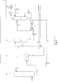
- la
figure 1 schématise un mode de réalisation du procédé selon l'art antérieur, - la
figure 2 schématise un mode de réalisation du procédé selon l'invention. - La présente invention propose une méthode simple et peu coûteuse car ne nécessitant qu'un petit nombre d'équipements additionnels, pour séparer la majeure partie des hydrocarbures co-absorbés par le solvant de la majeure partie des gaz acides absorbés par le solvant et ainsi de contrôler la teneur en hydrocarbures en tête de régénérateur.
- Elle concerne, de manière générale, un procédé de décarbonatation par lavage avec un solvant d'un gaz hydrocarboné, par exemple un gaz naturel, dans lequel on effectue les étapes suivantes :
- a) on met en contact ledit gaz avec une solution absorbante de manière à obtenir un gaz appauvri en CO2 et une solution absorbante chargée en CO2,
- b) on chauffe et on détend la solution absorbante chargée en CO2 à une pression et une température déterminées de manière à libérer une fraction gazeuse comportant des hydrocarbures et à obtenir une solution absorbante appauvrie en hydrocarbures, ladite pression et ladite température étant choisies de sorte que ladite fraction gazeuse comporte au moins 50% des hydrocarbures contenu dans ladite solution absorbante chargée en CO2 et au plus 35 % de CO2 contenu dans ladite solution absorbante chargée en CO2. On élimine les hydrocarbures de la phase concentrée par une étape d'incinération dédiée.
- c) on régénère thermiquement la solution absorbante appauvrie en composés hydrocarbures de manière à libérer un effluent gazeux riche en CO2 et à obtenir une solution absorbante régénérée. La régénération thermique peut être une distillation ou bien un entraînement des composés acides par de la vapeur, opération couramment nommé "strippage".
- Selon un mode de réalisation, au moins une partie de la solution absorbante régénérée obtenue à l'étape c) est recyclée à l'étape a) en tant que solution absorbante.
- A l'étape b) la solution absorbante est chauffée préférentiellement par échange avec un fluide du procédé à travers un échangeur de chaleur, mais tout autre moyen de chauffage permettant d'obtenir une température adéquat peut être utilisé. La solution absorbante ainsi chauffée subit une détente à une pression et une température déterminée de manière à libérer une fraction gazeuse comportant majoritairement des hydrocarbures et à obtenir une solution absorbante appauvrie en hydrocarbures. Les conditions de pression et température sont optimisées de sorte que la fraction gazeuse comporte au moins 50 % des hydrocarbures contenus dans la solution absorbante chargée en gaz acides et au plus 35 % des gaz acides contenus dans la solution absorbante chargée.
- En référence à la
figure 2 , le gaz à traiter est admis par la ligne 1 en fond d'un absorbeur 2. En tête de l'absorbeur 2, on récupère le gaz dont sont extraits les gaz acides absorbés par le solvant, injecté en tête d'absorbeur par la ligne 26, ainsi que les fractions des composés co-absorbés, notamment les hydrocarbures. Cet absorbeur opère en général à des températures proches ou légèrement supérieures à la température ambiante, typiquement comprises entre 20 et 100 °C, préférentiellement comprises entre 30 et 90 °C, et à des pressions typiquement comprises entre 10 et 200 bars, préférentiellement entre 20 et 100 bars. - Le gaz arrivant par le conduit 1 peut être un gaz naturel disponible à une pression comprise entre 10 et 200 bars, et à une température comprise entre 20 et 100 °C. Ce gaz comporte du CO2, éventuellement d'autres composés acides tels que de l'H2S, du COS, des mercaptans et des hydrocarbures.
- Le solvant riche en gaz acides obtenu en fond d'absorbeur par la ligne 4 est détendu par un moyen de détente 5, et admis dans un premier ballon de détente 6. Cette première étape de détente permet d'obtenir par la ligne 7 un gaz contenant la majeure partie des hydrocarbures légers co-absorbés par le solvant. Ce gaz peut éventuellement être lavé par une fraction du solvant régénéré et le gaz ainsi obtenu peut être utilisé comme gaz de fuel. Un tel lavage, facultatif, n'est cependant pas représenté ici. Le ballon de détente 6 opère à une pression P2 inférieure à celle de l'absorbeur 2 et supérieure à celle du ballon de détente 30. Cette pression est généralement fixée par les conditions d'utilisation du gaz de fuel, typiquement de l'ordre de 5 à 15 bars. Ce ballon opère à une température sensiblement identique à celle du solvant obtenu en fond de l'absorbeur 2.
- Le solvant riche en gaz acides obtenu après détente est envoyé par la ligne 8 vers un moyen de préchauffage. On a représenté sur la
Figure 1 un échangeur de chaleur 27 avec une utilité chaude mais tout autre moyen adéquat de préchauffage par échange avec des fluides à disposition peut être utilisé du moment qu'il permet de porter la température du solvant riche en gaz acide au niveau requis pour réaliser une vaporisation partielle des composés absorbés par le solvant. - Le solvant riche en gaz acides préchauffé est admis par la ligne 29, après détente éventuelle par un moyen de détente 28, dans le ballon 30 où s'effectue la séparation des gaz vaporisés et du solvant riche en gaz acides. Ce ballon 30 est opéré dans des conditions de température et de pression telles qu'on obtienne une vaporisation d'une fraction minoritaire de gaz acides absorbés par le solvant, généralement inférieure à 35 %, préférentiellement inférieure à 30 %, et d'une fraction majoritaire des hydrocarbures absorbés par le solvant, supérieure à 50 %, préférentiellement supérieure à 70 %. La pression du ballon 30 est inférieure à celle du ballon 6 et elle est supérieure à la pression atmosphérique, préférentiellement comprise entre 1.5 et 6 bars. La température du ballon 30 est comprise entre celle du solvant chargé en gaz acides obtenu en fond de l'absorbeur 2 et celle du solvant régénéré obtenu en fond du régénérateur 12. Cette température peut être comprise entre 50°C et 140°C.
- Le solvant obtenu en fond du ballon 30 est envoyé par la ligne 32, la pompe 33 et la ligne 34 vers un moyen de préchauffage. On a représenté sur la
Figure 2 un échangeur de chaleur 9 avec le solvant régénéré obtenu en fond de la colonne de régénération 12, mais tout autre moyen adéquat de préchauffage peut être utilisé. Le solvant riche en gaz acide ainsi préchauffé est admis par la ligne 11, après détente éventuelle par un moyen de détente 10, en tête du régénérateur 12. Dans ce régénérateur, les composés acides absorbés par le solvant, notamment le CO2, sont vaporisés par effet couramment nommé "strippage" avec de la vapeur générée par le rebouilleur 21 en fond du régénérateur. Ces gaz sont récupérés par la ligne 13 en tête du régénérateur, refroidis dans l'échangeur 14 et l'eau ainsi que le solvant contenu dans le gaz de tête du régénérateur qui sont majoritairement condensés, séparés dans le ballon de reflux 15 et recyclés comme reflux en tête de régénérateur par la ligne 20. Les conditions de température et de pression opératoires du régénérateur sont fonction du type de solvant mis en oeuvre. Le régénérateur 12 opère sous une pression généralement comprise entre la pression atmosphérique et 10 bars, préférentiellement comprise entre 1,05 et 3 bars. La température en fond du régénérateur est généralement comprise entre 100 et 200 °C, préférentiellement comprise entre 110 et 150 °C. - En fond du régénérateur 12, on obtient par la ligne 22 un flux de solvant régénéré chaud qui, après échange de chaleur avec le solvant riche en gaz acides dans l'échangeur 9, est recyclé via la ligne 23, la pompe 24 et la ligne 26 en tête de l'absorbeur 2.
- Les gaz libérés par vaporisation partielle dans le ballon 30 sont envoyés par la ligne 31 vers un incinérateur dédié. Les gaz acides séparés dans le ballon 15 sont admis dans la ligne 16 et peuvent être soit rejetés, soit envoyés vers un train de compression pour faire de l'EOR.
- La solution absorbante comporte une amine ou un mélange d'amines en solution dans de l'eau. Les amines peuvent être choisies parmi le groupe comportant les amines primaires, les amines secondaires, les amines secondaires stériquement encombrées, les amines tertiaires et des mélanges d'amines tertiaires et d'amines primaires ou secondaires.
- Concernant les amines primaires, elles peuvent être choisies, seule ou en mélange, parmi la monoéthanolamine (MEA), l'aminoéthyléthanolamine (AEEA), la diglycolamine, la 2-amino-2-méthyl-1-propanol et ses dérivés non N substitués.
- Concernant les amines secondaires, elles peuvent être choisies, seule ou en mélange, parmi la diéthanolamine (DEA), la diisopropanolamine (DIPA), la pipérazine et ses dérivés dans lesquels au moins un atome d'azote n'est pas substitué, la morpholine et ses dérivés non N substitués, la pipéridine et ses dérivés non N substitués, la N-(2'-hydroxyéthyl)-2-amino-2-méthyl-1-propanol , la N-(2'-hydroxypropyl)-2-amino-2-méthyl-1-propanol, la N-(2'-hydroxybutyl)-2-amino-2-méthyl-1-propanol.
- Concernant les amines tertiaires, elles peuvent être choisies, seule ou en mélange, parmi la méthyldiéthanolamine (MDEA), la triéthanolamine (TEA), l'éthyldiéthanolamine, la diéthyléthanolamine, la diméthyléthanolamine, la 1-méthyl-4-(3-diméthylaminopropyl)-pipérazine, la 1-éthyl-4-(diéthylaminoéthyl), la 1-méthyl-4-hydroxy-pipéridine, la 1-méthyl-2-hydroxyméthyl-pipéridine, la 1,2-bis-(2-diméthylaminoéthoxy)-éthane, le Bis(diméthylamino-3-propyl)éther, le Bis(diéthylamino-3-propyl)éther, le (diméthylamino-2-éthyl)-(diméthylamino-3-propyl)-éther, le (diéthylamino-2-éthyl)-(diméthylamino-3-propyl)-éther, le (diméthylamino-2-éthyl)-(diéthylamino-3-propyl)-éther, le (diéthylamino-2-éthyl)-(diéthylamino-3-propyl)-éther, la N-méthyl-N-(3-méthoxypropyl)-2-aminoéthanol, la N-méthyl-N-(3-méthoxypropyl)-1-amino-2-propanol, la N-méthyl-N-(3-méthoxypropyl)-1-amino-2-butanol, la N-éthyl-N-(3-méthoxypropyl)-2-aminoéthanol, la N-éthyl-N-(3-méthoxypropyl)-1-amino-2-propanol, la N-éthyl-N-(3-méthoxypropyl)-1-amino-2-butanol, la N-isopropyl-N-(3-méthoxypropyl)-2-aminoéthanol, la N-isopropyl-N-(3-méthoxypropyl)-1-amino-2-propanol, la N-isopropyl-N-(3-méthoxypropyl)-1-amino-2-butanol, la 1-(4-morpholino)-2-(méthylisopropylamino)-éthane, la 1-(4-morpholino)-2-(méthyltertiobutylamino)-éthane, la 1-(4-morpholino)-2-(diisopropylamino)-éthane, la 1-(4-morpholino)-2-(1-pipéridinyl)-éthane et la tertiobutyldiéthanolamine.
- Concernant les amines secondaires encombrées, elles peuvent être choisies, seule ou en mélange, parmi la N-(2'-hydroxyéthyl)-2-amino-2-méthyl-1-propanol, la N-(2'-hydroxypropyl)-2-amino-2-méthyl-1-propanol, la N-(2'-hydroxybutyl)-2-amino-2-methyl-1-propanol.
- Dans les mélanges d'amines tertiaires et d'amines primaires ou secondaires, les amines primaires ou secondaires (activateurs) peuvent être choisies parmi le groupe comportant, la Monoéthanolamine, la Diéthanolamine, la N-butyléthanolamine, la Aminoéthyléthanolamine, la Diglycolamine, la Pipérazine, la 1-Méthylpipérazine, la 2-Méthylpipérazine, la N-(2-hydroxyéthyl)pipérazine, la N-(2-aminoéthyl)pipérazine, la Morpholine, la 3-(méthylamino)propylamine, la 1,6-hexanediamine et tous ses dérivés diversement N-alkylés tels par exemple la N,N'-diméthyl-1,6-hexanediamine, la N-méthyl-1,6-hexanediamine ou la N,N',N'-triméthyl-1,6-hexanediamine.
- Enfin, la solution absorbante peut être choisie parmi le groupe constitué du sulfolane, le méthanol, la N-formyl morpholine, l'acétyl morpholine, le carbonate de propylène, le diméthyl éther polyethylène glycol ou la N-méthyl pyrrolidone ou un mélange d'amine avec un solvant physique et de l'eau.
- Les exemples exposés ci-après illustrent le fonctionnement et les avantages du procédé selon l'invention. Le premier exemple est donné à titre comparatif et illustre un procédé selon l'art antérieur. Le second exemple illustre le fonctionnement du procédé selon le mode de réalisation de l'invention. Enfin, le troisième exemple permet d'illustrer la performance de la présente invention pour le traitement des gaz comportant des teneurs plus importantes en composés aromatiques (BTX).
- Dans les exemples 1 et 2, on cherche à traiter 8.3 MMSm3/j d'un gaz naturel dont la composition est donnée Tableau 1. Les conditions standards sont 15 °C et 1 atm. Dans la suite du document, le terme HC désigne l'ensemble des coupes hydrocarbures depuis le méthane (C1) et comprenant également les aromatiques. Pour ces exemples, deux cas d'études sont présentés :
- le cas max CO2, correspondant à la teneur maximale en CO2 du gaz à traiter
- le cas max HC, correspondant à un cas appauvri en CO2 mais riche en HC lourdsTableau 1 - Composition du gaz brut à traiter Gaz Brut Cas Max CO2 %mol sec Cas Max HC %mol sec CO2 5.0484 2.3932 H2S 0.0005 0.0005 N2 0.3405 0.4935 C1 93.1154 92.6 C2 1.2419 3.3586 C3 0.2107 0.6955 C4 0.0335 0.2164 C5 0.0058 0.0879 C6+ hors aromatiques 0.0027 0.1496 Benzène 0.0003 0.0019 Toluène 0.0001 0.0011 Xylènes 0.0002 0.0018 C6+ désigne l'ensemble des coupes aliphatiques de C6 à C12. - Ce gaz entre dans l'absorbeur à une température de 52 °C sous une pression de 68.5 bars où il est mis en contact avec une solution aqueuse de MDEA (397 g/l) activée à la HEP (80 g/l). Le solvant arrive dans la colonne d'absorption à une température de 60 °C et à un débit de 290 Sm3/h pour le cas Max CO2 et 145 Sm3/h pour le cas Max HC. La colonne d'absorption est équipée de garnissage structuré. La hauteur de la zone d'absorption a été optimisée de façon à respecter les spécifications sur le gaz traité.
- Les spécifications requises sont les suivantes :
- 2 %mol de CO2 (1.8 % calculé) dans le gaz traité
- 1.45 ppm d'H2S dans le gaz traité
- 150 mg/Nm3 de VOC sur le gaz acide
- Le gaz naturel après traitement sort à un débit de 8 MMSm3/j avec la composition donnée au Tableau 2.
Tableau 2 - Composition du gaz traité Gaz Traité Cas Max CO2 %mol sec Cas Max HC %mol sec CO2 1.8092 0.6367 H2S 0 0 N2 0.3525 0.5026 C1 96.2925 94.2672 C2 1.284 3.4188 C3 0.2179 0.708 C4 0.0347 0.2202 C5 0.0059 0.0896 C6+ hors aromatiques 0.0027 0.1521 Benzène 0.0003 0.0019 Toluène 0.0001 0.0011 Xylènes 0.0002 0.0018 - Dans cet exemple, le schéma mis en oeuvre est illustré
figure 2 . Il ne contient pas le dispositif de contrôle de la teneur en HC dans le gaz acide. - Avec ce procédé, la composition du gaz acide obtenu en tête de régénérateur est donnée par le Tableau 3.
Tableau 3 - Composition du gaz acide obtenu avec un procédé selon l'art antérieur Gaz Traité Cas Max CO2 %mol sec Cas Max HC %mol sec CO2 99.69 99.66 ppmv sec H2S 151 282 N2 3.5 4.6 C1 2793 2784 C2 51 138 C3 6 21 C4 3.5 6 C5 1 1 C6+ hors aromatiques 4 63 Cycloalcanes 0 3 Benzène 3.5 4 Toluène 1 17 Ethyl Benzene 1 25 Xylènes 2 19 - Les teneurs VOC dans le gaz acide sont les suivantes :
- Cas Max CO2: 1600 mg/Nm3
- Cas Max HC : 3100 mg/Nm3
- Dans les deux cas, la spécification VOC dans le gaz acide n'étant pas respectée, il est nécessaire de mettre en oeuvre un incinérateur dédié au gaz acide. Dans ce cas, les dimensions de l'incinérateur, de modèle vertical à tirage naturel sont : Diamètre de la chambre de combustion : 3 500 mm, Hauteur de la chambre de combustion : 12 000 mm, Hauteur de la cheminée : 45 mètres.
- La consommation de Gaz de fuel dédiée à l'incinération du gaz acide est estimée à 726 kg/h.
- L'invention consiste à mettre en oeuvre une colonne à basse pression qui, après une légère préchauffe, permet de détendre l'amine riche pour évaporer les HC (par exemple les VOC) dissous dans le solvant tout en contrôlant la perte en CO2 et la taille du régénérateur en aval. Le gaz de flash ainsi obtenu est incinéré dans un incinérateur dédié. Dans cet exemple, la colonne de flash LP fonctionne aux conditions suivantes :
- Température de 75 °C sous 1.5 bars pour le cas Max CO2
- Température de 77 °C sous 1.5 bars pour le cas Max HC
- Les équipements additionnels illustrés
figure 1 sont les suivants : - Échangeur 9 pour préchauffe de l'amine riche (charge 4.5 MW).
- Colonne LP-Flash 12 (diamètre 3 m, hauteur : 10.8 m dont 1 lit de 2 m de garnissage).
- Pompe de circulation 15 (Puissance hydraulique = 52kW).
- Incinérateur LP Gaz de Flash (vertical à tirage naturel, diamètre de la chambre : 1 500 mm, hauteur de la chambre de combustion : 3 000 mm, cheminée 35 m).
- On aurait pu s'affranchir du ballon de flash MP 6.
- Avec ce procédé, la composition du gaz acide obtenu en tête de régénérateur est donnée par le Tableau 4.
Tableau 4 - Composition du gaz acide obtenu avec un procédé selon la présente invention Gaz Traité Cas Max CO2 %mol sec Cas Max HC %mol sec CO2 99.9809 99.9677 Ppmv sec Ppmv sec H2S 155 298 N2 0 0 C1 32 12 C2 1 1 C3 0 0 C4 0 0 C5 0 0 C6+ hors aromatiques 1 1 Cycloalcanes 0 0 Benzène 1 6 Toluène 1 3 Ethyl Benzene 1 4 Xylènes 0 2 - Les teneurs VOC dans le gaz acide sont les suivantes :
- Cas Max CO2: 30 mg/Nm3
- Cas Max HC : 60 mg/Nm3
- Dans les deux cas, la spécification VOC dans le gaz acide étant respectée, il n'est plus nécessaire de mettre en oeuvre un incinérateur dédié au gaz acide.
- En cas de compression et de refroidissement du gaz acide mis en pression, l'eau condensée par cette étape est nettement moins polluée par des hydrocarbures liquides que dans le procédé selon l'art antérieur. Il est alors possible de recycler cette eau sans traitement de purification des HC liquides.
- Pour ce cas, la consommation de Gaz de fuel dédiée à l'incinération LP est estimée à 15 kg/h.
- Cet exemple compare les teneurs en VOC d'un gaz acide issu du traitement d'un gaz brut riche en BTX par :
- Le procédé selon l'art antérieur illustré
figure 2 . - Le procédé selon la présente invention décrit
figure 1 . - Dans cet exemple, seules les teneurs en VOC du gaz acide ainsi que les consommations de Gaz de fuel dédiées à l'incinération sont comparées.
- Pour le procédé selon l'invention, la colonne de flash LP fonctionne à 87°C sous
1.5 bar. - On veut traiter 76 t/h d'un gaz brut contenant 3 % de CO2, 14 ppm d'H2S et
318 ppmv de BTX. La composition de ce gaz est donnée dans le Tableau 5 suivantTableau 5 - Composition du gaz de charge NOM DU FLUX Gaz de charge PRESSION (bar) 64.1 TEMPERATURE (deg.C) 36.82 Composition (%mol sec) DIOXYDE DE CARBONE 3.0409 SULFURE D'HYDROGÈNE 0.0014 H2O N2 0.8052 H2 0.018 METHANE 90.8092 ETHANE 4.1082 PROPANE 0.7592 ISOBUTANE 0.127 N-BUTANE 0.129 ISOPENTANE 0.058 N-PENTANE 0.026 N-HEXANE 0.0578 N-HEPTANE 0.024 N-OCTANE 0.0029 N-NONANE 0.0011 BENZENE 0.03 TOLUENE 0.0013 ETHYL-BENZENE 0.0005 Total HC hors BTX 96.1024 Total BTX 0.0318 Total HC 96.1342 - Ce gaz entre dans l'absorbeur à une température de 35.7 °C sous une pression de 64.1 bars où il est mis en contact avec une solution aqueuse de MDEA (397 g/l) activée à la HEP (80 g/l). Le solvant arrive dans la colonne d'absorption à une température de 44.5 °C et à un débit de 78 S m3/h. La colonne d'absorption est équipée d'une section plateaux et d'une section en garnissage structuré. La hauteur et l'agencement de la zone d'absorption ont été optimisés de façon à respecter les spécifications sur le gaz traité (50 ppmv de CO2 et 3 ppmv d'H2S). La composition du gaz traité est donnée par le Tableau 6 ci-après.
Tableau 6 - Composition du gaz traité NOM DU FLUX GAZ TRAITÉ PRESSION (bar) 63.2 TEMPERATURE (deg.C) 37.93 Composition (%mol) DIOXYDE DE CARBONE 0.0014 SULFURE D'HYDROGÈNE H2O 0.1396 N2 0.8297 H2 0.0186 METHANE 93.5285 ETHANE 4.2307 PROPANE 0.782 ISOBUTANE 0.1309 N-BUTANE 0.1329 ISOPENTANE 0.0598 N-PENTANE 0.0268 N-HEXANE 0.0595 N-HEPTANE 0.0247 N-OCTANE 0.003 N-NONANE 0.0011 BENZENE 0.0292 TOLUENE 0.0013 ETHYL-BENZENE 0.0005 Total HC hors BTX 98.9799 Total BTX 0.031 Total HC 99.0109 - L'amine chargée en gaz acides obtenue en fond d'absorbeur à une température de 60 °C est ensuite détendue dans un ballon de flash dit MP (Medium Pressure) sous 7.3 bar de façon à évaporer une partie des HC légers pour constituer du Gaz de fuel. Selon l'art antérieur, l'amine riche, une fois détendue, est préchauffée par l'amine régénérée avant d'être envoyée au régénérateur afin d'obtenir un solvant pauvre en gaz acide et un gaz dit gaz acide en tête contenant essentiellement du CO2, de l'H2S et une fraction d'hydrocarbures. Selon l'invention, l'amine riche détendue est préchauffée puis détendue une nouvelle fois (flash LP) à basse pression (ici 1.5 bar) avant de traverser l'échangeur amine/amine et d'être régénérée. Cette étape supplémentaire permet d'évaporer une fraction supplémentaire d'hydrocarbure plus lourd dont notamment des composés aromatiques. Les compositions des gaz acides et du gaz de flash LP sont données dans le Tableau 7 ci-après. Ce tableau montre aussi l'évolution des débits et des teneurs en VOC de ces gaz en fonction du type de procédé mis en oeuvre. Ces valeurs permettent de déterminer s'il est nécessaire d'incinérer le gaz acide et, si oui, quelle sera la consommation de Gaz de fuel Associée.
Tableau 7 - Composition du gaz acide et du gaz de flash selon le procédé considéré PROCEDE Selon art antérieur Selon invention NOM DU FLUX Gaz Acide vers Incinérateur Gaz LP vers Incinérateur ACID GAS vers évent PRESSION (bar) 1.2 1.2 1.2 TEMPERATURE (deg.C) 36.66 87.11 36.66 Composition (%mol) DIOXIDE DE CARBONE 95.5907 62.642 95.8987 SULFURE D'HYDROGÈNE 0.044 0.0281 0.0445 H2O 4.051 36.5875 4.051 N2 0.0007 0.0016 H2 METHANE 0.245 0.5855 0.0005 ETHANE 0.0152 0.0363 PROPANE 0.002 0.0048 ISOBUTANE 0.0003 0.0007 N-BUTANE 0.0003 0.0008 ISOPENTANE 0.0001 0.0002 N-PENTANE 0.0001 N-HEXANE 0.0003 0.0008 N-HEPTANE 0.0003 0.0007 N-OCTANE 0.0001 0.0002 N-NONANE 0.0001 0.0002 BENZENE 0.0474 0.105 0.0049 TOLUENE 0.0019 0.0042 0.0002 ETHYL-BENZENE 0.0007 0.0015 0.0001 Total HC hors BTX 0.2637 0.6303 0.0005 Total BTX 0.05 0.1107 0.0052 Total HC 0.3137 0.741 0.0057 DEBIT VOL. (Nm3/h) 3165 1252 2167 Teneur VOC (mg/Nm3) 3627.3 8846.7 187 Teneur BTX (mg/Nm3) 1675.3 3923.8 183.1 - Pour le procédé selon la présente invention, il n'est pas nécessaire d'incinérer le gaz acide du fait du gain de 95 % sur la teneur en VOC et notamment du gain de 89 % sur la teneur en composés aromatiques.
- Dans les deux cas, il est toutefois nécessaire de prévoir un incinérateur :
- pour incinérer le gaz acide dans le cas du procédé selon l'art antérieur
- pour incinérer le gaz de flash LP dans le cas de la présente invention
- Cet incinérateur sera cependant plus important et donc plus coûteux dans le cas du procédé selon l'art antérieur car le débit de gaz à incinérer est supérieur (plus 59 %). Le coût des incinérateurs n'a pas été estimé mais la consommation de Gaz de fuel a été évaluée pour illustrer le gain réalisé en mettant en oeuvre la présente invention. Selon l'art antérieur, l'incinération du gaz acide consomme environ 186 kg/h de Gaz de fuel contre 28 kg/h pour l'incinération du gaz de flash LP dans le cas de la présente invention, soit un gain de 85 %.
- On constate que l'eau récupérable dans le gaz acide, si elle est condensée après une étape de compression du gaz acide, contiendra nettement moins d'hydrocarbures.
- Selon l'invention le gaz peut être un gaz naturel, un gaz comportant au moins 50 ppmv d'hydrocarbures, et/ou un gaz comportant moins de 100 ppmv d'H2S.
- La fraction gazeuse comportant des hydrocarbures obtenue à l'étape b) peut être envoyée dans une unité de traitement autre qu'un incinérateur, par exemple le réseau de gaz de combustion.
- L'invention concerne également, un procédé de récupération assistée d'hydrocarbures (EOR) dans lequel on injecte dans un milieu souterrain l'effluent gazeux riche en CO2 obtenu à l'issue de l'étape c). Cette injection peut se faire via un puits afin de faciliter l'étape d'extraction d'hydrocarbures.
Claims (17)
- Procédé de décarbonatation par lavage avec un solvant d'un gaz hydrocarboné, par exemple un gaz naturel, dans lequel on effectue les étapes suivantes :a) on met en contact ledit gaz avec une solution absorbante de manière à obtenir un gaz appauvri en CO2 et une solution absorbante chargée en CO2 ;b) on chauffe et on détend la solution absorbante chargée en CO2, à une température comprise entre 50°C et 140°C, et à une pression comprise entre 1.5 et 6 bars, de manière à libérer une fraction gazeuse comportant des hydrocarbures et à obtenir une solution absorbante appauvrie en hydrocarbures, ladite pression et ladite température étant choisies de sorte que ladite fraction gazeuse comporte au moins 50% des hydrocarbures contenu dans ladite solution absorbante chargée en CO2 et au plus 35 % de CO2 contenu dans ladite solution absorbante chargée en CO2 ;c) on régénère thermiquement par strippage ou par distillation la solution absorbante appauvrie en composés hydrocarbures de manière à libérer un effluent gazeux riche en CO2 et à obtenir une solution absorbante régénérée,et dans lequel avant l'étape b) on détend la solution absorbante chargée en CO2 à une pression P2 comprise entre ladite pression utilisée à l'étape b) et une pression utilisée à l'étape a), et à une température sensiblement identique à celle de ladite solution absorbante chargée en CO2 obtenue après l'étape a).
- Procédé selon la revendication 1, dans lequel ladite pression et ladite température sont choisies de sorte que ladite fraction gazeuse comporte au moins 70% des hydrocarbures contenu dans ladite solution absorbante chargée en CO2 et moins de 30 % de CO2 contenu dans ladite solution absorbante chargée en CO2.
- Procédé selon l'une des revendications précédentes, dans lequel ladite température est comprise entre celle de ladite solution absorbante chargée en CO2 obtenue après l'étape a) et celle de ladite solution absorbante régénéré obtenu après l'étape c), et ladite pression est supérieure à la pression atmosphérique.
- Procédé selon l'une des revendications précédentes, dans lequel au moins une partie de la solution absorbante régénérée obtenue à l'étape c) est recyclée à l'étape a) en tant que solution absorbante.
- Procédé selon la revendication 1, dans lequel ladite pression P2 est comprise entre 5 et 15 bars.
- Procédé selon l'une des revendications précédentes, dans lequel la solution absorbante comporte une amine ou un mélange d'amines en solution dans de l'eau.
- Procédé selon la revendication 6, dans lequel l'amine est choisie parmi le groupe comportant les amines primaires, les amines secondaires, les amines secondaires stériquement encombrées, les amines tertiaires et des mélanges d'amines tertiaires et d'amines primaires ou secondaires.
- Procédé selon la revendication 7, dans lequel l'amine primaire est choisie, seule ou en mélange, parmi la monoéthanolamine (MEA), l'aminoéthyléthanolamine (AEEA), la diglycolamine, la 2-amino-2-méthyl-1-propanol et ses dérivés non N substitués.
- Procédé selon l'une des revendication 7 et 8, dans lequel l'amine secondaire est choisie, seule ou en mélange, parmi la diéthanolamine (DEA), la diisopropanolamine (DIPA), la pipérazine et ses dérivés dans lesquels au moins un atome d'azote n'est pas substitué, la morpholine et ses dérivés non N substitués, la pipéridine et ses dérivés non N substitués, la N-(2'-hydroxyéthyl)-2-amino-2-méthyl-1-propanol, la N-(2'-hydroxypropyl)-2-amino-2-méthyl-1-propanol, la N-(2'-hydroxybutyl)-2-amino-2-méthyl-1-propanol.
- Procédé selon l'une des revendication 7 à 9, dans lequel l'amine tertiaire est choisie, seule ou en mélange, parmi la méthyldiéthanolamine (MDEA), la triéthanolamine (TEA), l'éthyldiéthanolamine, la diéthyléthanolamine, la diméthyléthanolamine, la 1-méthyl-4-(3-diméthylaminopropyl)-pipérazine, la 1-éthyl-4-(diéthylaminoéthyl), la 1-méthyl-4-hydroxy-pipéridine, la 1-méthyl-2-hydroxyméthyl-pipéridine, la 1,2-bis-(2-diméthylaminoéthoxy)-éthane, le Bis(diméthylamino-3-propyl)éther, le Bis(diéthylamino-3-propyl)éther, le (diméthylamino-2-éthyl)-(diméthylamino-3-propyl)-éther, le (diéthylamino-2-éthyl)-(diméthylamino-3-propyl)-éther, le (diméthylamino-2-éthyl)-(diéthylamino-3-propyl)-éther, le (diéthylamino-2-éthyl)-(diéthylamino-3-propyl)-éther, la N-méthyl-N-(3-méthoxypropyl)-2-aminoéthanol, la N-méthyl-N-(3-méthoxypropyl)-1-amino-2-propanol, la N-méthyl-N-(3-méthoxypropyl)-1-amino-2-butanol, la N-éthyl-N-(3-méthoxypropyl)-2-aminoéthanol, la N-éthyl-N-(3-méthoxypropyl)-1-amino-2-propanol, la N-éthyl-N-(3-méthoxypropyl)-1-amino-2-butanol, la N-isopropyl-N-(3-méthoxypropyl)-2-aminoéthanol, la N-isopropyl-N-(3-méthoxypropyl)-1-amino-2-propanol, la N-isopropyl-N-(3-méthoxypropyl)-1-amino-2-butanol, la 1-(4-morpholino)-2-(méthylisopropylamino)-éthane, la 1-(4-morpholino)-2-(méthyltertiobutylamino)- éthane, la 1-(4-morpholino)-2-(diisopropylamino)-éthane, la 1-(4-morpholino)-2-(1-pipéridinyl)-éthane et la tertiobutyldiéthanolamine.
- Procédé selon l'une des revendication 7 à 10, dans lequel l'amine secondaire encombrée est choisie, seule ou en mélange, parmi la N-(2'-hydroxyéthyl)-2-amino-2-méthyl-1-propanol, la N-(2'-hydroxypropyl)-2-amino-2-méthyl-1-propanol, la N-(2'-hydroxybutyl)-2-amino-2-méthyl-1-propanol.
- Procédé selon l'une des revendication 7 à 11, dans lequel dans les mélanges d'amines tertiaires et d'amines primaires ou secondaires, les amines primaires ou secondaires sont choisies parmi le groupe comportant, la Monoéthanolamine, la Diéthanolamine, la N-butyléthanolamine, la Aminoéthyléthanolamine, la Diglycolamine, la Pipérazine, la 1-Méthylpipérazine, la 2-Méthylpipérazine, la N-(2-hydroxyéthyl)pipérazine, la N-(2-aminoéthyl)pipérazine, la Morpholine, la 3-(méthylamino)propylamine, la 1,6-hexanediamine et tous ses dérivés diversement N-alkylés tels par exemple la N,N'-diméthyl-1,6-hexanediamine, la N-méthyl-1,6-hexanediamine ou la N,N',N'-triméthyl-1,6-hexanediamine.
- Procédé selon l'une des revendications 1 à 12, dans lequel la solution absorbante est choisie parmi le groupe constitué du sulfolane, le méthanol, la N-formyl morpholine, l'acétyl morpholine, le carbonate de propylène, le diméthyl éther polyethylène glycol ou la N-méthyl pyrrolidone ou un mélange d'amine avec un solvant physique et de l'eau.
- Procédé selon l'une des revendications précédentes, dans lequel le gaz est un gaz naturel.
- Procédé selon l'une des revendications précédentes, dans lequel le gaz comporte au moins 50 ppmv d'hydrocarbures.
- Procédé selon l'une des revendications précédentes, dans lequel le gaz comporte moins de 100 ppmv d'H2S.
- Procédé selon une des revendications précédentes dans lequel on injecte dans un milieu souterrain ledit effluent gazeux riche en CO2 obtenu à l'issue de l'étape c), dans un procédé de récupération assistée d'hydrocarbures.
Applications Claiming Priority (2)
| Application Number | Priority Date | Filing Date | Title |
|---|---|---|---|
| FR1355593A FR3006912B1 (fr) | 2013-06-14 | 2013-06-14 | Procede de decarbonatation d'un gaz hydrocarbone |
| PCT/FR2014/051153 WO2014199036A2 (fr) | 2013-06-14 | 2014-05-19 | Procédé de décarbonatation d'un gaz hydrocarboné |
Publications (2)
| Publication Number | Publication Date |
|---|---|
| EP3007803A2 EP3007803A2 (fr) | 2016-04-20 |
| EP3007803B1 true EP3007803B1 (fr) | 2019-02-20 |
Family
ID=48980144
Family Applications (1)
| Application Number | Title | Priority Date | Filing Date |
|---|---|---|---|
| EP14811587.6A Active EP3007803B1 (fr) | 2013-06-14 | 2014-05-19 | Procédé de décarbonatation d'un gaz hydrocarboné |
Country Status (11)
| Country | Link |
|---|---|
| US (1) | US10213729B2 (fr) |
| EP (1) | EP3007803B1 (fr) |
| JP (1) | JP6445541B2 (fr) |
| CN (1) | CN105307752B (fr) |
| AU (1) | AU2014279984B2 (fr) |
| BR (1) | BR112015030558B1 (fr) |
| CA (1) | CA2914340C (fr) |
| FR (1) | FR3006912B1 (fr) |
| MY (1) | MY174075A (fr) |
| RU (1) | RU2666865C2 (fr) |
| WO (1) | WO2014199036A2 (fr) |
Families Citing this family (19)
| Publication number | Priority date | Publication date | Assignee | Title |
|---|---|---|---|---|
| FR3045401B1 (fr) * | 2015-12-17 | 2018-02-02 | IFP Energies Nouvelles | Solution absorbante a base de derives hydroxyles de la 1,6-hexanediamine et procede d'elimination de composes acides d'un effluent gazeux |
| MY186866A (en) * | 2016-02-08 | 2021-08-26 | Basf Se | Method for separating c5-c8 hydrocarbons and acid gases from a fluid stream |
| MA45401A (fr) | 2016-06-18 | 2019-04-24 | Think Tank 42 Pty Ltd | Procédé et système de capture et de recyclage du carbone |
| CN106997196B (zh) * | 2017-04-14 | 2019-07-16 | 长江大学 | 基于灰色关联分析法的mdea脱碳系统分析方法 |
| US10974194B2 (en) | 2017-07-18 | 2021-04-13 | Saudi Arabian Oil Company | System for flare gas recovery using gas sweetening process |
| US10981104B2 (en) * | 2018-04-12 | 2021-04-20 | Saudi Arabian Oil Company | System for flare gas recovery using gas sweetening process |
| JP7185421B2 (ja) | 2018-05-25 | 2022-12-07 | 株式会社東芝 | 酸性ガス吸収剤、酸性ガスの除去方法および酸性ガス除去装置 |
| GB201813839D0 (en) | 2018-06-26 | 2018-10-10 | Carbon Clean Solutions Ltd | System and process of capturing carbon dioxide from flue gases |
| US12059649B2 (en) | 2018-06-26 | 2024-08-13 | Carbon Clean Solutions Limited | Solvent and process for removing carbon dioxide from a gaseous mixture having high carbon dioxide partial pressures |
| EP3817839A1 (fr) | 2018-07-02 | 2021-05-12 | Carbon Clean Solutions Limited | Procédé et système pour retirer du dioxyde de carbone de solvants |
| CN110684575A (zh) * | 2018-07-06 | 2020-01-14 | 中国石油化工股份有限公司 | 一种脱除高压天然气中二氧化碳的方法 |
| CN109722317B (zh) * | 2019-03-01 | 2020-10-27 | 西安鸿钧睿泽新材料科技有限公司 | 基于湿法再生co2吸附材料的天然气脱碳系统及方法 |
| JP7336245B2 (ja) * | 2019-04-12 | 2023-08-31 | 三菱重工業株式会社 | Co2、h2s又はそれら双方の吸収液並びにco2又はh2s又はその双方の除去装置及び方法 |
| FR3099710B1 (fr) * | 2019-08-08 | 2021-08-06 | Ifp Energies Now | Procédé de traitement de gaz par absorption utilisant une régénération du solvant par flash chaud optimisée thermiquement |
| CN113431540A (zh) * | 2021-07-01 | 2021-09-24 | 河海大学 | 利用液态二甲醚在地层中渗透溶解的原油开采的方法 |
| CN113731119A (zh) * | 2021-09-10 | 2021-12-03 | 湖南大学 | 一种用于二氧化碳捕获阈值可控的液-液相变吸收剂 |
| JP7702205B2 (ja) * | 2021-09-15 | 2025-07-03 | 株式会社東芝 | 新規アミン化合物、酸性ガス吸収剤、酸性ガスの除去方法及び酸性ガス除去 |
| CN114231322B (zh) * | 2021-12-31 | 2023-04-28 | 北京派创石油技术服务有限公司 | 煤气净化及二氧化碳循环处理方法 |
| CN115253600B (zh) * | 2022-08-08 | 2024-03-05 | 华北电力大学(保定) | 一种具有良好循环解吸稳定性、低腐蚀性的相变吸收剂的制备与应用 |
Family Cites Families (18)
| Publication number | Priority date | Publication date | Assignee | Title |
|---|---|---|---|---|
| DE3236600A1 (de) * | 1982-10-02 | 1984-04-05 | Basf Ag, 6700 Ludwigshafen | Verfahren zum entfernen von co(pfeil abwaerts)2(pfeil abwaerts) und gegebenenfalls h(pfeil abwaerts)2(pfeil abwaerts)s aus erdgasen |
| DE3308088A1 (de) * | 1983-03-08 | 1984-09-27 | Basf Ag, 6700 Ludwigshafen | Verfahren zum entfernen von co(pfeil abwaerts)2(pfeil abwaerts) und/oder h(pfeil abwaerts)2(pfeil abwaerts)s aus gasen |
| DE3427134A1 (de) | 1984-07-24 | 1986-02-06 | Basf Ag, 6700 Ludwigshafen | Verfahren zum entfernen von co(pfeil abwaerts)2(pfeil abwaerts) und/oder h(pfeil abwaerts)2(pfeil abwaerts)s aus gasen |
| SU1279658A1 (ru) | 1985-01-03 | 1986-12-30 | Предприятие П/Я Р-6603 | Способ очистки газа от диоксида углерода |
| SU1733062A1 (ru) | 1990-04-23 | 1992-05-15 | Всесоюзный научно-исследовательский и проектный институт мономеров с опытным заводом | Способ очистки водородсодержащего газа от двуокиси углерода |
| CA2177449C (fr) * | 1996-05-20 | 2003-04-29 | Barry Steve Marjanovich | Methode de traitement d'un circuit gazeux pour en separer selectivement les gaz acides |
| JP3771708B2 (ja) * | 1998-03-23 | 2006-04-26 | 三菱重工業株式会社 | ガス中の二酸化炭素の除去方法 |
| US6881389B2 (en) * | 2002-09-24 | 2005-04-19 | Edg, Inc. | Removal of H2S and CO2 from a hydrocarbon fluid stream |
| FR2848218B1 (fr) * | 2002-12-10 | 2005-01-28 | Inst Francais Du Petrole | Procede de desacidification et de deshydratation d'un gaz naturel |
| ES2365474T3 (es) * | 2002-12-12 | 2011-10-06 | Fluor Corporation | Procedimiento de eliminación de gases ácidos. |
| RU2272228C1 (ru) * | 2005-03-30 | 2006-03-20 | Анатолий Васильевич Наумейко | Универсальный способ разделения и сжижения газа (варианты) и устройство для его осуществления |
| FR2895273B1 (fr) * | 2005-12-22 | 2008-08-08 | Inst Francais Du Petrole | Procede de desacidification d'un gaz avec une solution absorbante a regeneration fractionnee avec controle de la teneur en eau de la solution |
| ES2601386T3 (es) | 2006-05-18 | 2017-02-15 | Basf Se | Agentes de absorción de dióxido de carbono con demanda de energía de regeneración reducida |
| FR2916652B1 (fr) * | 2007-05-30 | 2009-07-24 | Inst Francais Du Petrole | Procede de traitement integre d'un gaz naturel permettant de realiser une desacidification complete |
| RU2385180C1 (ru) | 2008-08-21 | 2010-03-27 | Владимир Сергеевич Арутюнов | Способ очистки углеводородных газов |
| WO2010039785A1 (fr) | 2008-10-02 | 2010-04-08 | Fluor Technologies Corporation | Configurations et procédés d’élimination d’un gaz acide à pression élevée |
| JP2010209296A (ja) * | 2009-03-12 | 2010-09-24 | Chiyoda Kako Kensetsu Kk | 原料ガス中の有機硫黄化合物の除去方法及びそれに使用する触媒 |
| FR2956038B1 (fr) * | 2010-02-08 | 2013-11-22 | Inst Francais Du Petrole | Procede de desacidification d'un gaz par une solution absorbante avec liberation d'un effluent gazeux a partir de la solution absorbante et lavage de cet effluent par la solution absorbante regeneree |
-
2013
- 2013-06-14 FR FR1355593A patent/FR3006912B1/fr active Active
-
2014
- 2014-05-19 BR BR112015030558-0A patent/BR112015030558B1/pt active IP Right Grant
- 2014-05-19 JP JP2016518558A patent/JP6445541B2/ja not_active Expired - Fee Related
- 2014-05-19 MY MYPI2015704447A patent/MY174075A/en unknown
- 2014-05-19 CN CN201480033830.2A patent/CN105307752B/zh active Active
- 2014-05-19 US US14/898,306 patent/US10213729B2/en active Active
- 2014-05-19 WO PCT/FR2014/051153 patent/WO2014199036A2/fr not_active Ceased
- 2014-05-19 EP EP14811587.6A patent/EP3007803B1/fr active Active
- 2014-05-19 CA CA2914340A patent/CA2914340C/fr active Active
- 2014-05-19 AU AU2014279984A patent/AU2014279984B2/en active Active
- 2014-05-19 RU RU2016100753A patent/RU2666865C2/ru active
Non-Patent Citations (1)
| Title |
|---|
| None * |
Also Published As
| Publication number | Publication date |
|---|---|
| US20160144314A1 (en) | 2016-05-26 |
| WO2014199036A2 (fr) | 2014-12-18 |
| JP6445541B2 (ja) | 2018-12-26 |
| MY174075A (en) | 2020-03-09 |
| EP3007803A2 (fr) | 2016-04-20 |
| FR3006912B1 (fr) | 2016-07-08 |
| FR3006912A1 (fr) | 2014-12-19 |
| CA2914340A1 (fr) | 2014-12-18 |
| WO2014199036A3 (fr) | 2015-11-19 |
| CA2914340C (fr) | 2021-09-14 |
| AU2014279984A1 (en) | 2016-01-07 |
| CN105307752B (zh) | 2018-11-09 |
| US10213729B2 (en) | 2019-02-26 |
| RU2016100753A3 (fr) | 2018-03-30 |
| AU2014279984B2 (en) | 2018-05-17 |
| RU2666865C2 (ru) | 2018-09-12 |
| JP2016529087A (ja) | 2016-09-23 |
| CN105307752A (zh) | 2016-02-03 |
| BR112015030558B1 (pt) | 2021-11-03 |
| BR112015030558A2 (pt) | 2017-07-25 |
| RU2016100753A (ru) | 2017-07-19 |
Similar Documents
| Publication | Publication Date | Title |
|---|---|---|
| CA2914340C (fr) | Procede de decarbonatation d'un gaz hydrocarbone | |
| EP2168659B1 (fr) | Procédé de désacidification d'un gaz par solution absorbante avec contrôle de la démixtion | |
| EP2310110B1 (fr) | Solution absorbante a base de n,n,n',n'-tetramethylhexane-1,6-diamine et d'une amine comportant des fonctions amine primaire ou secondaire et procede d'elimination de composes acides d'un effluent gazeux | |
| EP2445614B1 (fr) | Procede de traitement de gaz acides | |
| US8858906B2 (en) | Process for removal of carbon dioxide from a gas | |
| US9943802B1 (en) | Enhancement of claus tail gas treatment with membrane and reducing step | |
| JP2019171378A (ja) | リッチ/リーン溶剤再生のためのストリッパー供給構成の最適化 | |
| FR2938454A1 (fr) | Procede de desacidification d'un gaz par une solution absorbante aux amines, avec section de lavage a l'eau | |
| JP2013517925A5 (fr) | ||
| CN101365526A (zh) | 二氧化碳回收中的胺类再生 | |
| FR2911516A1 (fr) | Procede de purification d'un melange gazeux contenant des gaz acides | |
| WO2014001664A1 (fr) | Solution absorbante a base de diamines tertiaires appartenant a la famille des aminoethylmorpholines encombrees et procede d'élimination de composes acides d'un effluent gazeux | |
| EP1911505B1 (fr) | Procédé de capture du CO2 avec intégration thermique du régénérateur | |
| WO2011138517A1 (fr) | Solution absorbante a base de ν,ν,ν',ν'- tétraéthyldiéthylènetriamine et procédé d'elimination de composes acides d'un effluent gazeux | |
| WO2011089332A1 (fr) | Procédé intégré de décarbonatation et de désulfuration d'une fumée de combustion | |
| FR3036975A1 (fr) | Procede d'elimination de composes acides d'un effluent gazeux avec une solution absorbante a base d'aminoethers tel que le bis-(3-dimethylaminopropoxy)-1,2-ethane | |
| FR3014101A1 (fr) | Solution absorbante a base de n,n,n',n'-tetramethyl-1,6-hexanediamine et de n,n,n',n'-tetramethyldiaminoether et procede d'elimination de composes acides d'un effluent gazeux | |
| WO2024180358A1 (fr) | Procédé de séparation sélective de sulfure d'hydrogène d'un mélange gazeux | |
| AU2024328907A1 (en) | Method and apparatus for the manufacture of a treated gas with reduced solvent losses | |
| FR3014329A1 (fr) | Procede integre de traitement de gaz par captation d'un metal lourd avec controle de l'humidite relative et absorption des composes acides | |
| FR3006603A1 (fr) | Procede de traitement d'un flux gazeux comprenant des mercaptans sans tamis d'adsorption | |
| FR2957268A1 (fr) | Solution absorbante a base de multiamines aromatiques et procede d'elimination de composes acides d'un effluent gazeux |
Legal Events
| Date | Code | Title | Description |
|---|---|---|---|
| PUAI | Public reference made under article 153(3) epc to a published international application that has entered the european phase |
Free format text: ORIGINAL CODE: 0009012 |
|
| AK | Designated contracting states |
Kind code of ref document: A2 Designated state(s): AL AT BE BG CH CY CZ DE DK EE ES FI FR GB GR HR HU IE IS IT LI LT LU LV MC MK MT NL NO PL PT RO RS SE SI SK SM TR |
|
| AX | Request for extension of the european patent |
Extension state: BA ME |
|
| 17P | Request for examination filed |
Effective date: 20160519 |
|
| RBV | Designated contracting states (corrected) |
Designated state(s): AL AT BE BG CH CY CZ DE DK EE ES FI FR GB GR HR HU IE IS IT LI LT LU LV MC MK MT NL NO PL PT RO RS SE SI SK SM TR |
|
| RIN1 | Information on inventor provided before grant (corrected) |
Inventor name: GONNARD, SEBASTIEN Inventor name: LALOUE, NICOLAS Inventor name: LEROY, AGNES Inventor name: PERDU, GAUTHIER |
|
| DAX | Request for extension of the european patent (deleted) | ||
| RAP1 | Party data changed (applicant data changed or rights of an application transferred) |
Owner name: IFP ENERGIES NOUVELLES |
|
| STAA | Information on the status of an ep patent application or granted ep patent |
Free format text: STATUS: EXAMINATION IS IN PROGRESS |
|
| 17Q | First examination report despatched |
Effective date: 20171205 |
|
| GRAP | Despatch of communication of intention to grant a patent |
Free format text: ORIGINAL CODE: EPIDOSNIGR1 |
|
| STAA | Information on the status of an ep patent application or granted ep patent |
Free format text: STATUS: GRANT OF PATENT IS INTENDED |
|
| INTG | Intention to grant announced |
Effective date: 20181030 |
|
| GRAS | Grant fee paid |
Free format text: ORIGINAL CODE: EPIDOSNIGR3 |
|
| GRAA | (expected) grant |
Free format text: ORIGINAL CODE: 0009210 |
|
| STAA | Information on the status of an ep patent application or granted ep patent |
Free format text: STATUS: THE PATENT HAS BEEN GRANTED |
|
| AK | Designated contracting states |
Kind code of ref document: B1 Designated state(s): AL AT BE BG CH CY CZ DE DK EE ES FI FR GB GR HR HU IE IS IT LI LT LU LV MC MK MT NL NO PL PT RO RS SE SI SK SM TR |
|
| REG | Reference to a national code |
Ref country code: GB Ref legal event code: FG4D Free format text: NOT ENGLISH |
|
| REG | Reference to a national code |
Ref country code: CH Ref legal event code: EP |
|
| REG | Reference to a national code |
Ref country code: DE Ref legal event code: R096 Ref document number: 602014041395 Country of ref document: DE |
|
| REG | Reference to a national code |
Ref country code: AT Ref legal event code: REF Ref document number: 1097435 Country of ref document: AT Kind code of ref document: T Effective date: 20190315 |
|
| REG | Reference to a national code |
Ref country code: IE Ref legal event code: FG4D Free format text: LANGUAGE OF EP DOCUMENT: FRENCH |
|
| REG | Reference to a national code |
Ref country code: NL Ref legal event code: FP |
|
| REG | Reference to a national code |
Ref country code: LT Ref legal event code: MG4D |
|
| REG | Reference to a national code |
Ref country code: NO Ref legal event code: T2 Effective date: 20190220 |
|
| PG25 | Lapsed in a contracting state [announced via postgrant information from national office to epo] |
Ref country code: SE Free format text: LAPSE BECAUSE OF FAILURE TO SUBMIT A TRANSLATION OF THE DESCRIPTION OR TO PAY THE FEE WITHIN THE PRESCRIBED TIME-LIMIT Effective date: 20190220 Ref country code: FI Free format text: LAPSE BECAUSE OF FAILURE TO SUBMIT A TRANSLATION OF THE DESCRIPTION OR TO PAY THE FEE WITHIN THE PRESCRIBED TIME-LIMIT Effective date: 20190220 Ref country code: PT Free format text: LAPSE BECAUSE OF FAILURE TO SUBMIT A TRANSLATION OF THE DESCRIPTION OR TO PAY THE FEE WITHIN THE PRESCRIBED TIME-LIMIT Effective date: 20190620 Ref country code: LT Free format text: LAPSE BECAUSE OF FAILURE TO SUBMIT A TRANSLATION OF THE DESCRIPTION OR TO PAY THE FEE WITHIN THE PRESCRIBED TIME-LIMIT Effective date: 20190220 |
|
| PG25 | Lapsed in a contracting state [announced via postgrant information from national office to epo] |
Ref country code: LV Free format text: LAPSE BECAUSE OF FAILURE TO SUBMIT A TRANSLATION OF THE DESCRIPTION OR TO PAY THE FEE WITHIN THE PRESCRIBED TIME-LIMIT Effective date: 20190220 Ref country code: HR Free format text: LAPSE BECAUSE OF FAILURE TO SUBMIT A TRANSLATION OF THE DESCRIPTION OR TO PAY THE FEE WITHIN THE PRESCRIBED TIME-LIMIT Effective date: 20190220 Ref country code: BG Free format text: LAPSE BECAUSE OF FAILURE TO SUBMIT A TRANSLATION OF THE DESCRIPTION OR TO PAY THE FEE WITHIN THE PRESCRIBED TIME-LIMIT Effective date: 20190520 Ref country code: IS Free format text: LAPSE BECAUSE OF FAILURE TO SUBMIT A TRANSLATION OF THE DESCRIPTION OR TO PAY THE FEE WITHIN THE PRESCRIBED TIME-LIMIT Effective date: 20190620 Ref country code: GR Free format text: LAPSE BECAUSE OF FAILURE TO SUBMIT A TRANSLATION OF THE DESCRIPTION OR TO PAY THE FEE WITHIN THE PRESCRIBED TIME-LIMIT Effective date: 20190521 Ref country code: RS Free format text: LAPSE BECAUSE OF FAILURE TO SUBMIT A TRANSLATION OF THE DESCRIPTION OR TO PAY THE FEE WITHIN THE PRESCRIBED TIME-LIMIT Effective date: 20190220 |
|
| REG | Reference to a national code |
Ref country code: AT Ref legal event code: MK05 Ref document number: 1097435 Country of ref document: AT Kind code of ref document: T Effective date: 20190220 |
|
| PG25 | Lapsed in a contracting state [announced via postgrant information from national office to epo] |
Ref country code: DK Free format text: LAPSE BECAUSE OF FAILURE TO SUBMIT A TRANSLATION OF THE DESCRIPTION OR TO PAY THE FEE WITHIN THE PRESCRIBED TIME-LIMIT Effective date: 20190220 Ref country code: ES Free format text: LAPSE BECAUSE OF FAILURE TO SUBMIT A TRANSLATION OF THE DESCRIPTION OR TO PAY THE FEE WITHIN THE PRESCRIBED TIME-LIMIT Effective date: 20190220 Ref country code: EE Free format text: LAPSE BECAUSE OF FAILURE TO SUBMIT A TRANSLATION OF THE DESCRIPTION OR TO PAY THE FEE WITHIN THE PRESCRIBED TIME-LIMIT Effective date: 20190220 Ref country code: RO Free format text: LAPSE BECAUSE OF FAILURE TO SUBMIT A TRANSLATION OF THE DESCRIPTION OR TO PAY THE FEE WITHIN THE PRESCRIBED TIME-LIMIT Effective date: 20190220 Ref country code: IT Free format text: LAPSE BECAUSE OF FAILURE TO SUBMIT A TRANSLATION OF THE DESCRIPTION OR TO PAY THE FEE WITHIN THE PRESCRIBED TIME-LIMIT Effective date: 20190220 Ref country code: SK Free format text: LAPSE BECAUSE OF FAILURE TO SUBMIT A TRANSLATION OF THE DESCRIPTION OR TO PAY THE FEE WITHIN THE PRESCRIBED TIME-LIMIT Effective date: 20190220 Ref country code: CZ Free format text: LAPSE BECAUSE OF FAILURE TO SUBMIT A TRANSLATION OF THE DESCRIPTION OR TO PAY THE FEE WITHIN THE PRESCRIBED TIME-LIMIT Effective date: 20190220 Ref country code: AL Free format text: LAPSE BECAUSE OF FAILURE TO SUBMIT A TRANSLATION OF THE DESCRIPTION OR TO PAY THE FEE WITHIN THE PRESCRIBED TIME-LIMIT Effective date: 20190220 |
|
| REG | Reference to a national code |
Ref country code: DE Ref legal event code: R097 Ref document number: 602014041395 Country of ref document: DE |
|
| PG25 | Lapsed in a contracting state [announced via postgrant information from national office to epo] |
Ref country code: SM Free format text: LAPSE BECAUSE OF FAILURE TO SUBMIT A TRANSLATION OF THE DESCRIPTION OR TO PAY THE FEE WITHIN THE PRESCRIBED TIME-LIMIT Effective date: 20190220 Ref country code: PL Free format text: LAPSE BECAUSE OF FAILURE TO SUBMIT A TRANSLATION OF THE DESCRIPTION OR TO PAY THE FEE WITHIN THE PRESCRIBED TIME-LIMIT Effective date: 20190220 |
|
| REG | Reference to a national code |
Ref country code: DE Ref legal event code: R119 Ref document number: 602014041395 Country of ref document: DE |
|
| PLBE | No opposition filed within time limit |
Free format text: ORIGINAL CODE: 0009261 |
|
| STAA | Information on the status of an ep patent application or granted ep patent |
Free format text: STATUS: NO OPPOSITION FILED WITHIN TIME LIMIT |
|
| REG | Reference to a national code |
Ref country code: CH Ref legal event code: PL |
|
| PG25 | Lapsed in a contracting state [announced via postgrant information from national office to epo] |
Ref country code: AT Free format text: LAPSE BECAUSE OF FAILURE TO SUBMIT A TRANSLATION OF THE DESCRIPTION OR TO PAY THE FEE WITHIN THE PRESCRIBED TIME-LIMIT Effective date: 20190220 |
|
| 26N | No opposition filed |
Effective date: 20191121 |
|
| PG25 | Lapsed in a contracting state [announced via postgrant information from national office to epo] |
Ref country code: CH Free format text: LAPSE BECAUSE OF NON-PAYMENT OF DUE FEES Effective date: 20190531 Ref country code: LI Free format text: LAPSE BECAUSE OF NON-PAYMENT OF DUE FEES Effective date: 20190531 Ref country code: MC Free format text: LAPSE BECAUSE OF FAILURE TO SUBMIT A TRANSLATION OF THE DESCRIPTION OR TO PAY THE FEE WITHIN THE PRESCRIBED TIME-LIMIT Effective date: 20190220 |
|
| REG | Reference to a national code |
Ref country code: BE Ref legal event code: MM Effective date: 20190531 |
|
| PG25 | Lapsed in a contracting state [announced via postgrant information from national office to epo] |
Ref country code: LU Free format text: LAPSE BECAUSE OF NON-PAYMENT OF DUE FEES Effective date: 20190519 Ref country code: SI Free format text: LAPSE BECAUSE OF FAILURE TO SUBMIT A TRANSLATION OF THE DESCRIPTION OR TO PAY THE FEE WITHIN THE PRESCRIBED TIME-LIMIT Effective date: 20190220 |
|
| PG25 | Lapsed in a contracting state [announced via postgrant information from national office to epo] |
Ref country code: TR Free format text: LAPSE BECAUSE OF FAILURE TO SUBMIT A TRANSLATION OF THE DESCRIPTION OR TO PAY THE FEE WITHIN THE PRESCRIBED TIME-LIMIT Effective date: 20190220 |
|
| PG25 | Lapsed in a contracting state [announced via postgrant information from national office to epo] |
Ref country code: DE Free format text: LAPSE BECAUSE OF NON-PAYMENT OF DUE FEES Effective date: 20191203 Ref country code: IE Free format text: LAPSE BECAUSE OF NON-PAYMENT OF DUE FEES Effective date: 20190519 |
|
| PG25 | Lapsed in a contracting state [announced via postgrant information from national office to epo] |
Ref country code: BE Free format text: LAPSE BECAUSE OF NON-PAYMENT OF DUE FEES Effective date: 20190531 |
|
| PG25 | Lapsed in a contracting state [announced via postgrant information from national office to epo] |
Ref country code: CY Free format text: LAPSE BECAUSE OF FAILURE TO SUBMIT A TRANSLATION OF THE DESCRIPTION OR TO PAY THE FEE WITHIN THE PRESCRIBED TIME-LIMIT Effective date: 20190220 |
|
| PG25 | Lapsed in a contracting state [announced via postgrant information from national office to epo] |
Ref country code: HU Free format text: LAPSE BECAUSE OF FAILURE TO SUBMIT A TRANSLATION OF THE DESCRIPTION OR TO PAY THE FEE WITHIN THE PRESCRIBED TIME-LIMIT; INVALID AB INITIO Effective date: 20140519 Ref country code: MT Free format text: LAPSE BECAUSE OF FAILURE TO SUBMIT A TRANSLATION OF THE DESCRIPTION OR TO PAY THE FEE WITHIN THE PRESCRIBED TIME-LIMIT Effective date: 20190220 |
|
| PGFP | Annual fee paid to national office [announced via postgrant information from national office to epo] |
Ref country code: NL Payment date: 20210526 Year of fee payment: 8 |
|
| PG25 | Lapsed in a contracting state [announced via postgrant information from national office to epo] |
Ref country code: MK Free format text: LAPSE BECAUSE OF FAILURE TO SUBMIT A TRANSLATION OF THE DESCRIPTION OR TO PAY THE FEE WITHIN THE PRESCRIBED TIME-LIMIT Effective date: 20190220 |
|
| REG | Reference to a national code |
Ref country code: NL Ref legal event code: MM Effective date: 20220601 |
|
| PG25 | Lapsed in a contracting state [announced via postgrant information from national office to epo] |
Ref country code: NL Free format text: LAPSE BECAUSE OF NON-PAYMENT OF DUE FEES Effective date: 20220601 |
|
| PGFP | Annual fee paid to national office [announced via postgrant information from national office to epo] |
Ref country code: NO Payment date: 20250520 Year of fee payment: 12 |
|
| PGFP | Annual fee paid to national office [announced via postgrant information from national office to epo] |
Ref country code: FR Payment date: 20250526 Year of fee payment: 12 |
|
| PGFP | Annual fee paid to national office [announced via postgrant information from national office to epo] |
Ref country code: GB Payment date: 20260309 Year of fee payment: 13 |