EP3007312A1 - Wireless charger - Google Patents
Wireless charger Download PDFInfo
- Publication number
- EP3007312A1 EP3007312A1 EP15189084.5A EP15189084A EP3007312A1 EP 3007312 A1 EP3007312 A1 EP 3007312A1 EP 15189084 A EP15189084 A EP 15189084A EP 3007312 A1 EP3007312 A1 EP 3007312A1
- Authority
- EP
- European Patent Office
- Prior art keywords
- support
- bottom support
- housing
- wireless charger
- portable terminal
- Prior art date
- Legal status (The legal status is an assumption and is not a legal conclusion. Google has not performed a legal analysis and makes no representation as to the accuracy of the status listed.)
- Withdrawn
Links
Images


Classifications
-
- H—ELECTRICITY
- H02—GENERATION; CONVERSION OR DISTRIBUTION OF ELECTRIC POWER
- H02J—CIRCUIT ARRANGEMENTS OR SYSTEMS FOR SUPPLYING OR DISTRIBUTING ELECTRIC POWER; SYSTEMS FOR STORING ELECTRIC ENERGY
- H02J7/00—Circuit arrangements for charging or depolarising batteries or for supplying loads from batteries
- H02J7/0042—Circuit arrangements for charging or depolarising batteries or for supplying loads from batteries characterised by the mechanical construction
- H02J7/0044—Circuit arrangements for charging or depolarising batteries or for supplying loads from batteries characterised by the mechanical construction specially adapted for holding portable devices containing batteries
-
- F—MECHANICAL ENGINEERING; LIGHTING; HEATING; WEAPONS; BLASTING
- F16—ENGINEERING ELEMENTS AND UNITS; GENERAL MEASURES FOR PRODUCING AND MAINTAINING EFFECTIVE FUNCTIONING OF MACHINES OR INSTALLATIONS; THERMAL INSULATION IN GENERAL
- F16M—FRAMES, CASINGS OR BEDS OF ENGINES, MACHINES OR APPARATUS, NOT SPECIFIC TO ENGINES, MACHINES OR APPARATUS PROVIDED FOR ELSEWHERE; STANDS; SUPPORTS
- F16M13/00—Other supports for positioning apparatus or articles; Means for steadying hand-held apparatus or articles
-
- F—MECHANICAL ENGINEERING; LIGHTING; HEATING; WEAPONS; BLASTING
- F16—ENGINEERING ELEMENTS AND UNITS; GENERAL MEASURES FOR PRODUCING AND MAINTAINING EFFECTIVE FUNCTIONING OF MACHINES OR INSTALLATIONS; THERMAL INSULATION IN GENERAL
- F16M—FRAMES, CASINGS OR BEDS OF ENGINES, MACHINES OR APPARATUS, NOT SPECIFIC TO ENGINES, MACHINES OR APPARATUS PROVIDED FOR ELSEWHERE; STANDS; SUPPORTS
- F16M3/00—Portable or wheeled frames or beds, e.g. for emergency power-supply aggregates, compressor sets
-
- H—ELECTRICITY
- H02—GENERATION; CONVERSION OR DISTRIBUTION OF ELECTRIC POWER
- H02J—CIRCUIT ARRANGEMENTS OR SYSTEMS FOR SUPPLYING OR DISTRIBUTING ELECTRIC POWER; SYSTEMS FOR STORING ELECTRIC ENERGY
- H02J50/00—Circuit arrangements or systems for wireless supply or distribution of electric power
- H02J50/10—Circuit arrangements or systems for wireless supply or distribution of electric power using inductive coupling
-
- H—ELECTRICITY
- H02—GENERATION; CONVERSION OR DISTRIBUTION OF ELECTRIC POWER
- H02J—CIRCUIT ARRANGEMENTS OR SYSTEMS FOR SUPPLYING OR DISTRIBUTING ELECTRIC POWER; SYSTEMS FOR STORING ELECTRIC ENERGY
- H02J50/00—Circuit arrangements or systems for wireless supply or distribution of electric power
- H02J50/90—Circuit arrangements or systems for wireless supply or distribution of electric power involving detection or optimisation of position, e.g. alignment
-
- H—ELECTRICITY
- H02—GENERATION; CONVERSION OR DISTRIBUTION OF ELECTRIC POWER
- H02J—CIRCUIT ARRANGEMENTS OR SYSTEMS FOR SUPPLYING OR DISTRIBUTING ELECTRIC POWER; SYSTEMS FOR STORING ELECTRIC ENERGY
- H02J7/00—Circuit arrangements for charging or depolarising batteries or for supplying loads from batteries
- H02J7/02—Circuit arrangements for charging or depolarising batteries or for supplying loads from batteries for charging batteries from ac mains by converters
- H02J7/04—Regulation of charging current or voltage
Definitions
- the following description relates to a wireless battery charger.
- a wireless charger is an apparatus capable of charging a battery without a direct physical connection to the battery's electrical contacts, and typically includes a terminal body around which a power-transmitting coil is wound.
- the battery includes or is connected to a wireless power receiver, which has a power-receiving coil that can interface with the charger's power-transmitting coil.
- Batteries of this type are used in, for example, portable terminals, such as mobile phones, and other portable battery-powered devices.
- the charging efficiency of such a wireless charging arrangement usually is optimized when the battery's power-receiving coil is placed on or adjacent to the terminal body so as to be in close proximity to a central portion of the power-transmitting coil, thus minimizing battery charging time.
- Wireless chargers of the related art typically have a structure onto which the battery is simply placed but lack structure for aligning the battery's power-receiving coil with the central portion of the power-transmitting coil, thus often compromising charging efficiency of the battery.
- wireless chargers are often maintained in a stand-by mode, which wastes energy.
- a power source remains connected to and powers the wireless charger to sense the approach of a portable terminal to be charged, thus unnecessarily consuming power.
- a general aspect of the disclosed examples provides a wireless charger that optimizes charging efficiency in the charging of portable terminals (mobile phones, or the like) of various sizes.
- a wireless charger includes a housing with an insertion hole through which a portable terminal can be inserted, and a transmitting coil in the housing disposed to face a receiving coil of an inserted portable terminal.
- a pair of laterally spaced side supports in the housing are disposed to move laterally toward and away from each other on opposite sides of an inserted portable terminal, while a bottom support in the housing is disposed to move lengthwise of the housing and support a portion of the bottom of an inserted portable terminal.
- the side supports are mechanically linked to the bottom support such that movement of the bottom support is coordinated with movement of the side supports.
- the upper end of one or both side supports may be inclined (tapered) to facilitate insertion of a portable terminal into the housing.
- One or more elastic members may be interposed between the housing and any one or more of the side and bottom supports to provide a return force for the supports after the portable terminal is removed from the housing.
- the bottom support may comprise two separate bottom support portions, each connected to a separate side support to form two support assemblies; and movement of each support assembly may be guided by a guide protrusion slidably engaged with a guide rail inclined with respect to the side supports and the bottom support.
- Each support assembly may be L-shaped.
- the gradient of the guide rail may substantially correspond to an aspect ratio of an insertable portable terminal.
- a power transfer unit including gears coordinates movement of the bottom support and at least one of the side supports.
- the power transfer unit may have a first gear that meshes with teeth on the bottom of a side support and is rotated by lateral movement of the side support; and a second gear that meshes with the first gear and with teeth on the bottom support to move the bottom support lengthwise of the housing.
- Still another aspect provides a wireless charger having improved efficiency by preventing the consumption of standby power before beginning a charging process.
- a wireless charger having improved efficiency by preventing the consumption of standby power before beginning a charging process.
- a switch between the charger and a power source is controlled by movement of one of the side supports or the bottom support.
- Words describing spatial relationships such as “below,” “beneath,” “under,” “lower,” “bottom,” “above,” “over,” “upper,” “top,” “left,” “right,” “side” and “lateral,” may be used to conveniently describe relationships of one device or elements with other devices or elements. Such words are to be interpreted as encompassing a device oriented as illustrated in the drawings, and in other orientations in use or operation.
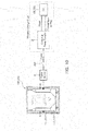
- a wireless charger 10 may include a housing 11 having a top insertion hole 13 through which a mobile phone or other type of portable terminal 20 may be inserted; and a transmitting coil 12 in the housing disposed to face a receiving coil 23 of the portable terminal 20 when inserted in the housing 11.
- FIG. 2 demonstrates that charging efficiency is reduced as a function of the degree to which the center C R of the receiving coil 23 is offset from the center C T of the transmitting coil 12 in the horizontal (C 1 ) direction and/or the vertical (C 2 ) direction.
- the best charging efficiency (66.80%) is achieved when the center C T of the transmitting coil 12 and the center C R of the receiving coil 23 are aligned with each other.
- optimal charging efficiency is achieved when the center C T of the transmitting coil 12 and the center C R of the receiving coil 23 are aligned with each other or are in close proximity to each other.
- a wireless charger 100 has a housing 110 including an insertion hole 115 through which an electronic device such as a portable terminal or the like can be inserted into the housing.
- a transmitting coil 120 is disposed to face the receiving coil of the portable terminal when inserted into the housing.
- the housing 110 includes upright side supports 111 spaced to engage the sides of the portable terminal and a bottom support comprising bottom support portions 113 positioned to support the bottom of the portable terminal. These supports 111, 113 thus cradle the portable terminal, preferably elastically. See elastic members (compression springs) 111c, 113c in FIGS. 5A, 5B (described below).
- the lateral supports 111 and the bottom support portions 113 preferably are interlocked as described below such that the bottom support portions 113 are moved by a predetermined amount according to movement of the side supports 111, preferably at a predetermined ratio.
- lengthwise movement of the bottom support portions 113 is a function of lateral movement of the side supports 111. That movement occurs when a portable terminal wider than the space between the side supports in a non-deflected state is inserted into or removed from the housing 110.
- portable terminals (mobile phones), for example, MP1, MP2, come in various sizes.
- the transmitting coil 120 fixed and laterally centered in the charger housing 110
- substantially equal movement of the side supports 111 optimally keeps the centrally positioned receiving coil (R X , R 1 , R 2 ) of the inserted portable terminal laterally centered in the housing, and thus laterally centered on the transmitting coil 120 (T X ) regardless of the terminal's size.
- each of the bottom support portions 113 is in the form of an inclined, inward extension of its respective lateral support 111, thus resulting in an interlocked structure such that the bottom support portion 113 is moved downward or returned according to lateral movement of its side support 111.
- the side supports 111 may be elastically supported, thus elastically cradling the sides of an inserted portable terminal and resulting in a stable structure.
- FIGS. 3 , 4 , 5A and 5B illustrate the housing 110 as having a box-like shape
- the housing 110 may have various shapes according to desired style or applications.
- the insertion hole 115 leads to a cavity 116 in the housing that may have the general shape of the portable terminals to be charged and may have a size sufficient to accommodate and cradle portable terminals such as MP1 and MP2 as shown, or larger portable terminals.
- the cavity 116 may be as long as the portable terminals to be cradled in the housing 110.
- a hole formed in the housing 110, having a shape in which one surface of the housing 110 is opened to cradle the portable terminal, or the like, may be used.
- the housing 110 may include guide rails 114 that are inclined with respect to the side supports 111 and the bottom support portions 113 as described below.
- Each of the guide rails 114 (one at each side) may be disposed adjacent to a side support 111 and its respective bottom support portion 113.
- the gradient of the guide rails 114 may be determined as substantially corresponding to the aspect ratio (length:width) of the portable terminals (e.g., MP1 and MP2) to be cradled.
- the side supports 111 and the bottom support portions 113 may protrude into the cavity 116 as shown in FIGS. 5A and 5B and a vertical support portion 111 and a horizontal support portion 113 may be horizontally provided.
- the side supports 111 may be firm or elastically deformable. Depending on the size of a portable terminal inserted into cavity 116, the side supports 111 may undergo lateral sliding movement, and may squeeze the sides of the portable terminal.
- the upper end of one or both lateral supports 111 i.e., the end portion which a portable terminal first encounters when inserted, may have a tapered part 111a inclined laterally outward and upward to facilitate insertion of a portable terminal and/or outward movement of the side support(s) 111.
- the bottom support portions 113 may be firm or elastically deformable and/or may undergo sliding movement; and they may press on the lower corners of a portable terminal inserted into the cavity 116. 111.
- each of the side supports 111 is connected to a respective bottom support portion 113 to form an L-shaped assembly having a guide protrusion 112 disposed adjacent to a respective guide rail 114.
- Guide protrusion 112 may extend from any portion of the assembly and is engaged in the guide rail 114.
- the guide protrusions 112 may be elastically coupled to their respective guide rails 114 and may be mounted so as to be returned to original positions after a portable terminal is removed from the charger.
- each guide protrusion 112 is moved downward and laterally outward along a respective guide rail 114 as the side supports 111 are spread apart, and the bottom support portions 113 are lowered to accommodate most of the length of the portable terminal in the cavity.
- the center C T of the transmitting coil 120 disposed in the housing 110 and the center C R of the receiving coil 120 which is aligned with the center of the portable terminal, are substantially aligned with each other or are in close proximity to each other, thus optimizing charging efficiency.
- a restoring force applied to any part of each such assembly will provide a common restoring force for the entire assembly.
- a restoring force may be provided by a first elastic member 111c located between the side support 111 and the housing 110.
- a second elastic member 113c may be provided between the bottom support portion 113 and the housing 110.
- the illustrated first example of FIGS. 3-5B has a guide protrusion 112 on either the lateral support 111 or the bottom support portion 113, and the guide rail 114 is carried by the housing 110.
- the guide protrusion may be carried by the housing 110 and the guide rail may be carried by the lateral support 111 or the bottom support portion 113.
- FIGS. 5A and 5B show that a wireless charger 100 according to this first example may be flexibly used depending on the sizes of the portable terminals to be charged.
- FIG. 5A illustrates a case in which a first portable terminal MP1 having a relatively small size is inserted into the wireless charger 100. It can be seen from FIG. 5A that movements of the side supports 111 and the bottom support portions 113 are relatively small (M1).
- FIG. 5B illustrates a case in which a second portable terminal MP2 having a relatively large size is inserted into the wireless charger 100. It can be seen from FIG. 5B that movements of the side supports 111 and the bottom support portions 113 are relatively large (M2).
- a wireless charger 200 has some features in common with the first example but a different arrangement for coordinating movement of the side and bottom supports for an inserted portable terminal.
- This example has a housing 210 including an insertion hole 215 through which a portable terminal may be inserted; and a transmitting coil 220 disposed to face the receiving coil of a portable terminal inserted into the housing.
- the housing 210 may include lateral supports 211 spaced to engage the sides of the portable terminal and a bottom support 213 positioned to support the bottom of the portable terminal. These supports 211, 213 thus cradle the portable terminal, preferably elastically. See elastic members (compression springs) 211c, 213c in FIGS. 8A, 8B ).
- the lateral supports 211 and the bottom support 213 may be interlocked by gears 212 and 214, which rotate in fixed positions in the housing, such that the bottom support 213 is moved by a predetermined amount according to movement of the lateral supports 211, i.e., at a fixed ratio.
- the gears 212 and 214 may be saw-toothed wheels (pinions).
- the center C T of the transmitting coil 220 and the center C R of the receiving coil (R 1 , R 2 , etc.) are aligned with each other or are in close proximity to each other, thereby optimizing charging efficiency. That is because, as explained previously, the charger's transmitting coil and the phones' receiving coils are laterally centered; the aspect ratios of phones of different sizes generally fall within a narrow range; and the side and bottom phone supports within the charger's housing move proportionally.
- the side supports 211 may be elastically supported, thus elastically cradling the sides of an inserted portable terminal and resulting in a stable structure.
- FIGS. 6 , 7 , 8A and 8B illustrate the housing 210 as having a box-like shape
- the housing 210 may have various shapes according to desired style or applications.
- the insertion hole 215 leads to a cavity 216 in the housing that may have the general shape of the portable terminals to be charged and may have a size sufficient to accommodate portable terminals such as MP1 and MP2 as shown, or larger portable terminals.
- the cavity 216 may be as long as the portable terminals to be cradled in the housing 210.
- a (cavity??) provided in the housing 210 a shape in which one surface of the housing 210 is opened to cradle the portable terminal, or the like may be used.
- the side supports 211 and the bottom support 213 may protrude into the cavity 216 as shown in FIGS. 8A and 8B .
- the side supports 211 and the bottom support 213 are interlocked with each other by gears 212 and 214, such as the saw-toothed wheels shown and described below.
- a pair of vertical support portions 211 may be horizontally provided, and one of the horizontal support portions 213 may be connected to all of the vertical support portions 211 on both sides, or a pair of horizontal support portions 213 may be respectively connected to the vertical support portions 211 on both sides.
- the side supports 211 of this example may be firm or elastically deformable.
- the side supports 211 may undergo lateral sliding movement, and may squeeze the sides of the portable terminal.
- the upper end of one or both side supports 211 i.e., the end portion which a portable terminal first encounters when inserted, may have a tapered part 211a inclined laterally outward and upward to facilitate insertion of a portable terminal and/or outward movement of the lateral supports 211.
- the bottom support 213 may be firm or elastically deformable and may press on a bottom portion of a portable terminal inserted into the cavity 216. Further, the bottom support 213, which is connected to (interlocked with) the side supports 211 by the gears 212 and 214, moves downward together with the side supports 211 in mutual fashion. In other words, the bottom support 213 is downwardly moved by outward movement of the side supports 211, and vice versa, as explained below.
- a first gear 212 of a saw-toothed wheel and a second gear 214 of a saw-toothed wheel are engaged with each other.
- the first gear 212 also is engaged with a first sawtooth rack 211b provided in the bottom of the lateral support 211 and the second gear 214 is engaged with a second sawtooth rack 213a provided in the end of the bottom support 213.
- the first rack 211b moves laterally outward (as a portable terminal is inserted into the housing)
- the first gear 212 is rotated in a counterclockwise direction.
- FIGS. 6 , 7 , 8A and 8B show a mirror-image arrangement of these gears and racks at the right side of the charger.
- the movement ratio of the side support 211 and the bottom support 213 depends on the number of saw teeth of the first gear 212 and the second gear 214, and may be determined by taking account of the aspect ratios (widths and lengths) of the portable terminals MP1 and MP2.
- Alternative arrangements may include, for example, more than two gears on each side between the side supports 211 and the bottom support 213.
- the center C T of the transmitting coil 220 in the housing 210 and the center C R of the receiving coils R1 or R2 are substantially aligned with each other or are in close proximity to each other, thus optimizing charging efficiency.
- an elastic member 211c may be provided between each side support 211 and the housing 210.
- an elastic member 213c may be provided between the bottom support 213 and the housing 210.
- FIGS. 8A and 8B show that a wireless charger 200 according to this second example may be flexibly used depending on the sizes of the portable terminals to be charged.
- FIG. 8A illustrates a case in which the first portable terminal MP1 having a relatively small size is inserted into the wireless charger 200. It can be seen from FIG. 8A that movements of the side supports 211 and the bottom support 213 are relatively small (M1).
- FIG. 8B illustrates a case in which a second portable terminal MP2 having a relatively large size is inserted into the wireless charger 200. It can be seen from FIG. 8B that movements of the side supports 211 and the bottom support 213 are relatively large (M2).
- FIGS. 9 and 10 illustrate a power transfer principle of a wireless charger that contemplates use of the charger with portable terminal MP1 or MP2.
- FIG. 9 shows how power is transferred to the portable terminals from the wireless chargers 100 and 200, but without an energy-conserving arrangement.
- the power may be supplied from a power source 1 and be transferred to the transmitting coils 120 and 220 by control of a control unit 2 (a concept including a power transfer), and the transmitting coils 120 and 220 may receive the power through a receiving coil 23 of the portable terminal.
- the control unit 2 is continually supplied with the power from the power source 1 in order for the transmitting coils 120 and 220 to sense the receiving part of the portable terminal, for instance, the receiving coil 23 may consume a predetermined amount of power, even in a case in which the portable terminal is not being charged. This is power which is unnecessarily wasted while the portable terminal is not being charged.
- FIG. 10 shows an example of an energy-conserving power transfer arrangement used for the wireless chargers 100 and 200 and other examples according to this disclosure.
- a switch 300 between the power source 1 and the control unit 2
- the power will not be transferred to the control unit 2 from the power source 1 when the portable terminal is not in a charging state. This is accomplished, for example, in the wireless chargers 100 and 200, by mechanically linking movement of any one of the side supports 111, 211 and the bottom support (portions) 113, 213 to the switch 300.
- a switch 310 may have a structure in which a tact switch 313 is provided between the power source 1 and the control unit 2, and the tact switch 313 may be compressed to be operated according to the extension of a side support 111 or 211 or bottom support (portion) 113 or 213.
- a spring 311 providing an elastic force maybe provided between the either of the side supports 111 and 211, or the bottom support (portion) 113 and 213, and the tact switch 313, and a metal plate 312 may be further provided to a portion at which the spring 311 is in contact with the tact switch 313 in order to improve connection performance.
- a switch 320 may disconnect a supply line between the power source 1 and the control unit 2, and elastic coupling structures may be formed at the respective end portions of the disconnected supply line.
- the switch 320 may be implemented so that the elastic members may be compressed by extension of one of the side supports 111 and 211 or the bottom support (portions) 113 and 213 connected to each other.
- the switch 320 may be implemented so that an elastic body 322 having a coil spring structure may be mounted on one end of the disconnected supply line connected to the power source 1 or the control unit 2, an elastic body 321 having an elastic piece shape may be mounted on the other end thereof, and the elastic body 322 having the coil spring structure and the elastic body 321 having the elastic piece shape may be in contact with each other while the elastic body 322 having the coil spring structure and the elastic body 321 having the elastic piece shape are pushed according to the extension of a side support 111 and 211 or bottom support (portion) 113 and 213.
- an end portion of the elastic body 322 having the coil spring structure may be provided with the metal plate 323 to improve connection performance.
- a switch 330 may disconnect a supply line between the power source 1 and the control unit 2, and elastic coupling structures may be formed at the respective end portions of the disconnected supply line.
- the switch 330 may be implemented so that the elastic members may be compressed by extension of the side support 111 and 211 or the bottom support (portion) 113 and 213 connected to each other. Since the present example has a shape in which the elastic body 322 having the coil spring structure in the example of FIG. 12 is changed to a conductor sponge 332, a detailed description thereof will be omitted.
- a switch 340 may disconnect a supply line between the power source 1 and the control unit 2, and elastic coupling structures may be formed at the respective end portions of the disconnected supply line.
- the switch 340 may be implemented so that the elastic members may be compressed according to the extension of either a lateral support 111 and 211 or a bottom support (portion) 113 and 213 connected to each other.
- the present example is basically the same implementation scheme as that of FIG. 12 , but the supply line connected to the power source 1 may be connected to the side support 111 and 211 or the bottom support (portion) 113 and 213, and the side support 111 and 211 or the bottom support (portion) 113 and 213 may be directly in contact with the supply line connected to the control unit 2.
- the side support 111 and 211 or the bottom support (portion) 113 and 213 connected to the supply line may be formed in a structure in which power may be transferred by a wire or the like therein.
- an end portion of the supply line connected to the control unit 2 may be provided with an elastic body 342 having a coil spring structure or an elastic body having an elastic piece shape (not illustrated) in order to improve contact performance, and an end portion of the elastic body 342 having the coil spring structure or the elastic body having the elastic piece shape may be provided with an elastic plate 343.
- a switch 350 may disconnect a supply line between the power source 1 and the control unit 2, and elastic coupling structures may be formed at the respective end portions of the disconnected supply line.
- the switch 350 may be implemented so that the elastic members may be compressed according to the extension of the side support 111 and 211 or the bottom support (portion) 113 and 213 connected to each other. Since the present example has a shape in which the elastic body 342 having the coil spring structure in the exemplary embodiment of FIG. 14 is changed to a conductor sponge 352, a detailed description thereof will be omitted.
- a switch 350 may disconnect a supply line between the power source 1 and the control unit 2, and a separate controller 362 may be provided between the disconnected supply lines.
- the wireless chargers 100 and 200 may include a proximity sensor 361 such as an ultrasonic sensor, a capacitive sensor, or the like capable of sensing an approach of a portable terminal in a case in which the portable terminal is inserted into the wireless chargers 100 and 200, such that the power may be transferred or disconnected through the supply line by a manipulation of the controller 362 according to the sensing of the approaching of the portable terminal.
- a switch 360 may disconnect a supply line between the power source 1 and the control unit 2, and a controller 361 including a separate hall sensor may be provided between the disconnected supply lines.
- a magnet 362 may be provided to one end of a side support 111 and 211 or the bottom support (portion) 113 and 213 so as to come into proximity with the controller 361 according to the extension of the side support 111 and 211 or the bottom support (portion) 113 and 213.
- the hall sensor senses the approaching of the magnet 362, such that it may be sensed that the portable terminal is inserted into the wireless chargers.
- a transistor switch 371 may be installed between the power sources 1 and 1' and the control unit 2 (power input terminal) of a wireless charger circuit, and a spring 372 may be connected to a base terminal (in a case of BJT) or a gate terminal (in a case of FET).
- a voltage may be applied to the base terminal or the gate terminal, such that the transistor switch is turned on.
- the power sources and the wireless charger circuit may be connected.
- the power sources and the wireless charger circuit may be disconnected from each other.
- a transistor switch 381 may be installed between the power sources 1 and 1' and the control unit 2 (power input terminal) of a wireless charger circuit, and a conductor sponge 382 may be connected to a base terminal (in a case of BJT) or a gate terminal (in a case of FET).
- a voltage may be applied to the base terminal or the gate terminal, such that the transistor switch is turned on.
- the power sources and the wireless charger circuit may be connected.
- the power sources and the wireless charger circuit may be disconnected from each other.
Abstract
Description
- This application claims the benefit of
Korean Patent Application Nos. 10-2014-0136561 10-2015-0026237 - The following description relates to a wireless battery charger.
- A wireless charger is an apparatus capable of charging a battery without a direct physical connection to the battery's electrical contacts, and typically includes a terminal body around which a power-transmitting coil is wound. To receive power from the charger, the battery includes or is connected to a wireless power receiver, which has a power-receiving coil that can interface with the charger's power-transmitting coil. Batteries of this type are used in, for example, portable terminals, such as mobile phones, and other portable battery-powered devices. The charging efficiency of such a wireless charging arrangement usually is optimized when the battery's power-receiving coil is placed on or adjacent to the terminal body so as to be in close proximity to a central portion of the power-transmitting coil, thus minimizing battery charging time. Wireless chargers of the related art typically have a structure onto which the battery is simply placed but lack structure for aligning the battery's power-receiving coil with the central portion of the power-transmitting coil, thus often compromising charging efficiency of the battery.
The lack of uniformity in case sizes of portable terminals, such as mobile phones, makes this a fairly widespread problem. - Further, such wireless chargers are often maintained in a stand-by mode, which wastes energy. In this mode, a power source remains connected to and powers the wireless charger to sense the approach of a portable terminal to be charged, thus unnecessarily consuming power.
- This Summary is provided to introduce a selection of concepts in a simplified form that are further described below in the Detailed Description. This Summary is not intended to identify key features or essential features of the claimed subject matter, nor is it intended to be used as an aid in determining the scope of the claimed subject matter.
- A general aspect of the disclosed examples provides a wireless charger that optimizes charging efficiency in the charging of portable terminals (mobile phones, or the like) of various sizes. In general, such a wireless charger includes a housing with an insertion hole through which a portable terminal can be inserted, and a transmitting coil in the housing disposed to face a receiving coil of an inserted portable terminal. A pair of laterally spaced side supports in the housing are disposed to move laterally toward and away from each other on opposite sides of an inserted portable terminal, while a bottom support in the housing is disposed to move lengthwise of the housing and support a portion of the bottom of an inserted portable terminal. The side supports are mechanically linked to the bottom support such that movement of the bottom support is coordinated with movement of the side supports.
- The upper end of one or both side supports may be inclined (tapered) to facilitate insertion of a portable terminal into the housing.
- One or more elastic members may be interposed between the housing and any one or more of the side and bottom supports to provide a return force for the supports after the portable terminal is removed from the housing.
- According to another aspect, the bottom support may comprise two separate bottom support portions, each connected to a separate side support to form two support assemblies; and movement of each support assembly may be guided by a guide protrusion slidably engaged with a guide rail inclined with respect to the side supports and the bottom support.
- Each support assembly may be L-shaped.
- The gradient of the guide rail may substantially correspond to an aspect ratio of an insertable portable terminal.
- According to yet another aspect, a power transfer unit including gears coordinates movement of the bottom support and at least one of the side supports.
- The power transfer unit may have a first gear that meshes with teeth on the bottom of a side support and is rotated by lateral movement of the side support; and a second gear that meshes with the first gear and with teeth on the bottom support to move the bottom support lengthwise of the housing.
- Still another aspect provides a wireless charger having improved efficiency by preventing the consumption of standby power before beginning a charging process.
According to this aspect, which also includes movable side supports and a bottom support for an inserted portable terminal, a switch between the charger and a power source is controlled by movement of one of the side supports or the bottom support. -
-
FIG. 1A is a perspective view of a generalized housing of embodiments of the wireless chargers showing the general position of a power-transmitting coil therein; -
FIG. 1B is a perspective view of a typical portable terminal (mobile phone) usable with the wireless charger, showing the general position of its power-receiving coil; -
FIG. 2 is a diagram illustrating receiving coil charging efficiency as a function of relative position of centers of the transmitting coil and the receiving coil of the wireless charger and a portable terminal, respectively; -
FIG. 3 is a perspective view of a first example of the wireless charger; -
FIG. 4 is a perspective view similar toFIG. 3 showing certain parts of that example in different positions; -
FIG. 5A is a cross-sectional view of the first example cradling a mobile phone for charging; -
FIG. 5B is a cross-sectional view of the first example cradling a larger mobile phone for charging; -
FIG. 6 is a perspective view of a second example of the wireless charger according to a second example; -
FIG. 7 is a perspective view similar toFIG. 6 showing certain parts of that example in different positions; -
FIG. 8A is a cross-sectional view of the second example cradling a mobile phone for charging; -
FIG.8B is a cross-sectional view of the second example cradling a larger mobile phone for charging; -
FIGS. 9 and10 are schematic illustrations of a power transfer principle for the wireless charger; and -
FIGS. 11 through 19 are schematic illustrations of various arrangements for minimizing standby power consumption of the wireless charger. - Throughout the drawings and the detailed description, the same reference numerals refer to the same elements. The drawings may not be to scale, and the relative size, proportions, and depiction of elements in the drawings may be exaggerated for clarity, illustration, and convenience.
- The following detailed description is provided to assist the reader in gaining a comprehensive understanding of the methods, apparatuses, and/or systems described herein. However, various changes, modifications, and equivalents of the methods, apparatuses, and/or systems described herein will be apparent to persons skilled in the art. Sequences of operations described herein are merely examples, and are not limited to those set forth herein, but may be changed as will be apparent to persons skilled in the art, with the exception of operations necessarily occurring in a certain order. Also, descriptions of functions and constructions that are well known to persons skilled in the art may have been omitted for increased clarity and conciseness.
- The features described herein may be embodied in different forms, and are not to be construed as being limited to the examples described herein. Rather, the examples described herein have been provided so that this disclosure will be thorough and complete, and will convey the full scope of the disclosure to persons skilled in the art.
- Words describing spatial relationships, such as "below," "beneath," "under," "lower," "bottom," "above," "over," "upper," "top," "left," "right," "side" and "lateral," may be used to conveniently describe relationships of one device or elements with other devices or elements. Such words are to be interpreted as encompassing a device oriented as illustrated in the drawings, and in other orientations in use or operation.
- Referring to
FIGS. 1A and 1B , awireless charger 10 may include ahousing 11 having atop insertion hole 13 through which a mobile phone or other type ofportable terminal 20 may be inserted; and a transmittingcoil 12 in the housing disposed to face areceiving coil 23 of theportable terminal 20 when inserted in thehousing 11.
FIG. 2 demonstrates that charging efficiency is reduced as a function of the degree to which the center CR of thereceiving coil 23 is offset from the center CT of the transmittingcoil 12 in the horizontal (C1) direction and/or the vertical (C2) direction. The best charging efficiency (66.80%) is achieved when the center CT of the transmittingcoil 12 and the center CR of the receivingcoil 23 are aligned with each other. Thus, optimal charging efficiency is achieved when the center CT of the transmittingcoil 12 and the center CR of the receivingcoil 23 are aligned with each other or are in close proximity to each other. - Referring to
FIGS. 3 and4 , awireless charger 100 according to a first example has ahousing 110 including aninsertion hole 115 through which an electronic device such as a portable terminal or the like can be inserted into the housing. A transmittingcoil 120 is disposed to face the receiving coil of the portable terminal when inserted into the housing. Thehousing 110 includes upright side supports 111 spaced to engage the sides of the portable terminal and a bottom support comprisingbottom support portions 113 positioned to support the bottom of the portable terminal. These supports 111, 113 thus cradle the portable terminal, preferably elastically. See elastic members (compression springs) 111c, 113c inFIGS. 5A, 5B (described below).
The lateral supports 111 and thebottom support portions 113 preferably are interlocked as described below such that thebottom support portions 113 are moved by a predetermined amount according to movement of the side supports 111, preferably at a predetermined ratio. In other words, lengthwise movement of thebottom support portions 113 is a function of lateral movement of the side supports 111. That movement occurs when a portable terminal wider than the space between the side supports in a non-deflected state is inserted into or removed from thehousing 110. - As shown in
FIGS. 5A and 5B , portable terminals (mobile phones), for example, MP1, MP2, come in various sizes. With the transmittingcoil 120 fixed and laterally centered in thecharger housing 110, substantially equal movement of the side supports 111 optimally keeps the centrally positioned receiving coil (RX, R1, R2) of the inserted portable terminal laterally centered in the housing, and thus laterally centered on the transmitting coil 120 (TX) regardless of the terminal's size. Even if those two coils (TX, RX) are not precisely centered lengthwise, optimal lengthwise alignment of their centers (CT, CR) is achieved because the aspect ratios of phones of different sizes (length to width) generally fall within a narrow range, and the side supports 111 and thebottom support portions 113 move proportionally due to their interlocked arrangement (described below). - In this first example, each of the
bottom support portions 113 is in the form of an inclined, inward extension of its respectivelateral support 111, thus resulting in an interlocked structure such that thebottom support portion 113 is moved downward or returned according to lateral movement of itsside support 111. The side supports 111 may be elastically supported, thus elastically cradling the sides of an inserted portable terminal and resulting in a stable structure. - Although
FIGS. 3 ,4 ,5A and 5B illustrate thehousing 110 as having a box-like shape, thehousing 110 may have various shapes according to desired style or applications. Theinsertion hole 115 leads to acavity 116 in the housing that may have the general shape of the portable terminals to be charged and may have a size sufficient to accommodate and cradle portable terminals such as MP1 and MP2 as shown, or larger portable terminals. Thecavity 116 may be as long as the portable terminals to be cradled in thehousing 110. For example, a hole formed in thehousing 110, having a shape in which one surface of thehousing 110 is opened to cradle the portable terminal, or the like, may be used. - The
housing 110 may includeguide rails 114 that are inclined with respect to the side supports 111 and thebottom support portions 113 as described below. Each of the guide rails 114 (one at each side) may be disposed adjacent to aside support 111 and its respectivebottom support portion 113. Further, the gradient of theguide rails 114 may be determined as substantially corresponding to the aspect ratio (length:width) of the portable terminals (e.g., MP1 and MP2) to be cradled. - The side supports 111 and the
bottom support portions 113 may protrude into thecavity 116 as shown inFIGS. 5A and 5B and avertical support portion 111 and ahorizontal support portion 113 may be horizontally provided.
The side supports 111 may be firm or elastically deformable. Depending on the size of a portable terminal inserted intocavity 116, the side supports 111 may undergo lateral sliding movement, and may squeeze the sides of the portable terminal. The upper end of one or both lateral supports 111, i.e., the end portion which a portable terminal first encounters when inserted, may have a taperedpart 111a inclined laterally outward and upward to facilitate insertion of a portable terminal and/or outward movement of the side support(s) 111. - The
bottom support portions 113 may be firm or elastically deformable and/or may undergo sliding movement; and they may press on the lower corners of a portable terminal inserted into thecavity 116. 111.
As shown inFIGS. 3-5B , each of the side supports 111 is connected to a respectivebottom support portion 113 to form an L-shaped assembly having aguide protrusion 112 disposed adjacent to arespective guide rail 114.Guide protrusion 112 may extend from any portion of the assembly and is engaged in theguide rail 114. The guide protrusions 112 may be elastically coupled to theirrespective guide rails 114 and may be mounted so as to be returned to original positions after a portable terminal is removed from the charger. - When a portable terminal (e.g, MP1 or MP2) displaces the lateral supports 111 outward during insertion into the
cavity 116, eachguide protrusion 112 is moved downward and laterally outward along arespective guide rail 114 as the side supports 111 are spread apart, and thebottom support portions 113 are lowered to accommodate most of the length of the portable terminal in the cavity. As a result, the center CT of the transmittingcoil 120 disposed in thehousing 110 and the center CR of the receivingcoil 120, which is aligned with the center of the portable terminal, are substantially aligned with each other or are in close proximity to each other, thus optimizing charging efficiency. - Since each of the side supports 111 is connected to a
bottom support portion 113, thus forming a substantially integral or interlocked assembly, a restoring force applied to any part of each such assembly will provide a common restoring force for the entire assembly. For example, a restoring force may be provided by
a firstelastic member 111c located between theside support 111 and thehousing 110. Alternatively or in addition, a secondelastic member 113c may be provided between thebottom support portion 113 and thehousing 110. Thus, only any one of the firstelastic member 111c and the secondelastic member 113c may be provided, or both may be provided. - The illustrated first example of
FIGS. 3-5B has aguide protrusion 112 on either thelateral support 111 or thebottom support portion 113, and theguide rail 114 is carried by thehousing 110. Alternatively, the guide protrusion may be carried by thehousing 110 and the guide rail may be carried by thelateral support 111 or thebottom support portion 113. -
FIGS. 5A and 5B show that awireless charger 100 according to this first example may be flexibly used depending on the sizes of the portable terminals to be charged.
FIG. 5A illustrates a case in which a first portable terminal MP1 having a relatively small size is inserted into thewireless charger 100. It can be seen fromFIG. 5A that movements of the side supports 111 and thebottom support portions 113 are relatively small (M1). By comparison,FIG. 5B illustrates a case in which a second portable terminal MP2 having a relatively large size is inserted into thewireless charger 100. It can be seen fromFIG. 5B that movements of the side supports 111 and thebottom support portions 113 are relatively large (M2). Since movements of the side supports 111 and thebottom support portions 113 are interlocked with each other, it can be seen in either case (MP1, MP2) that the center CT of the transmitting coil TX (120) and the center CR of the receiving coil RX, which is located at the center of the portable terminals MP1 and MP2, are substantially aligned with each other or are in close proximity to each other. - Referring to
FIGS. 6 and7 , awireless charger 200 according to a second example has some features in common with the first example but a different arrangement for coordinating movement of the side and bottom supports for an inserted portable terminal. This example has ahousing 210 including aninsertion hole 215 through which a portable terminal may be inserted; and a transmittingcoil 220 disposed to face the receiving coil of a portable terminal inserted into the housing. Thehousing 210 may includelateral supports 211 spaced to engage the sides of the portable terminal and abottom support 213 positioned to support the bottom of the portable terminal. These supports 211, 213 thus cradle the portable terminal, preferably elastically. See elastic members (compression springs) 211c, 213c inFIGS. 8A, 8B ). - The lateral supports 211 and the
bottom support 213 may be interlocked bygears bottom support 213 is moved by a predetermined amount according to movement of the lateral supports 211, i.e., at a fixed ratio. - In this example, the
gears wireless charger 200 according to this second example, regardless of the sizes of the portable terminals MP1 and MP2 (seeFIGS. 8A, 8B ), the center CT of the transmittingcoil 220 and the center CR of the receiving coil (R1, R2, etc.) are aligned with each other or are in close proximity to each other, thereby optimizing charging efficiency. That is because, as explained previously, the charger's transmitting coil and the phones' receiving coils are laterally centered; the aspect ratios of phones of different sizes generally fall within a narrow range; and the side and bottom phone supports within the charger's housing move proportionally.
In this embodiment, too, the side supports 211 may be elastically supported, thus elastically cradling the sides of an inserted portable terminal and resulting in a stable structure. - Although
FIGS. 6 ,7 ,8A and 8B illustrate thehousing 210 as having a box-like shape, thehousing 210 may have various shapes according to desired style or applications. Theinsertion hole 215 leads to acavity 216 in the housing that may have the general shape of the portable terminals to be charged and may have a size sufficient to accommodate portable terminals such as MP1 and MP2 as shown, or larger portable terminals. Thecavity 216 may be as long as the portable terminals to be cradled in thehousing 210. For example, a (cavity??) provided in thehousing 210, a shape in which one surface of thehousing 210 is opened to cradle the portable terminal, or the like may be used. - The side supports 211 and the
bottom support 213 may protrude into thecavity 216 as shown inFIGS. 8A and 8B . The side supports 211 and thebottom support 213 are interlocked with each other bygears vertical support portions 211 may be horizontally provided, and one of thehorizontal support portions 213 may be connected to all of thevertical support portions 211 on both sides, or a pair ofhorizontal support portions 213 may be respectively connected to thevertical support portions 211 on both sides.
The side supports 211 of this example may be firm or elastically deformable. Depending on the size of a portable terminal inserted intocavity 216, the side supports 211 may undergo lateral sliding movement, and may squeeze the sides of the portable terminal. The upper end of one or both side supports 211, i.e., the end portion which a portable terminal first encounters when inserted, may have a taperedpart 211a inclined laterally outward and upward to facilitate insertion of a portable terminal and/or outward movement of the lateral supports 211. - The
bottom support 213 may be firm or elastically deformable and may press on a bottom portion of a portable terminal inserted into thecavity 216. Further, thebottom support 213, which is connected to (interlocked with) the side supports 211 by thegears bottom support 213 is downwardly moved by outward movement of the side supports 211, and vice versa, as explained below. - As illustrated on the left sides of
FIGS. 6 ,7 ,8A and 8B , afirst gear 212 of a saw-toothed wheel and asecond gear 214 of a saw-toothed wheel are engaged with each other. Thefirst gear 212 also is engaged with a firstsawtooth rack 211b provided in the bottom of thelateral support 211 and thesecond gear 214 is engaged with a secondsawtooth rack 213a provided in the end of thebottom support 213. Thus, when thefirst rack 211b moves laterally outward (as a portable terminal is inserted into the housing), thefirst gear 212 is rotated in a counterclockwise direction. Thereby, thesecond gear 214 is rotated in a clockwise direction and thebottom support 213 engaged with thesecond gear 214 is moved downward.FIGS. 6 ,7 ,8A and 8B show a mirror-image arrangement of these gears and racks at the right side of the charger. The movement ratio of theside support 211 and thebottom support 213 depends on the number of saw teeth of thefirst gear 212 and thesecond gear 214, and may be determined by taking account of the aspect ratios (widths and lengths) of the portable terminals MP1 and MP2. Alternative arrangements may include, for example, more than two gears on each side between the side supports 211 and thebottom support 213. - When a portable terminalis inserted into the
housing 210, the center CT of the transmittingcoil 220 in thehousing 210 and the center CR of the receiving coils R1 or R2 are substantially aligned with each other or are in close proximity to each other, thus optimizing charging efficiency. - Since the
side support 211, thebottom support 213, and the first andsecond gears side support 211, thebottom support 213 and the first andsecond gears housing 210 will provide a common restoring force for all those components. Thus, anelastic member 211c may be provided between eachside support 211 and thehousing 210. Alternatively or in addition, anelastic member 213c may be provided between thebottom support 213 and thehousing 210. Meanwhile, since theside support 211 and thebottom support portion 213 are moved in a state in which they are interlocked with each other, any one of theelastic member -
FIGS. 8A and 8B show that awireless charger 200 according to this second example may be flexibly used depending on the sizes of the portable terminals to be charged.
FIG. 8A illustrates a case in which the first portable terminal MP1 having a relatively small size is inserted into thewireless charger 200. It can be seen fromFIG. 8A that movements of the side supports 211 and thebottom support 213 are relatively small (M1).FIG. 8B illustrates a case in which a second portable terminal MP2 having a relatively large size is inserted into thewireless charger 200. It can be seen fromFIG. 8B that movements of the side supports 211 and thebottom support 213 are relatively large (M2). Since movements of the side supports 211 and thebottom support 213 are interlocked with each other, it can be seen in either case (MP1, MP2) that the center CT of the transmitting coil TX (220) and the center CR of the receiving coil RX, which is located at the center of the portable terminal, are substantially aligned with each other or are in close proximity to each other. -
FIGS. 9 and10 illustrate a power transfer principle of a wireless charger that contemplates use of the charger with portable terminal MP1 or MP2. -
FIG. 9 shows how power is transferred to the portable terminals from thewireless chargers power source 1 and be transferred to the transmitting coils 120 and 220 by control of a control unit 2 (a concept including a power transfer), and the transmittingcoils coil 23 of the portable terminal. In this case, thecontrol unit 2 is continually supplied with the power from thepower source 1 in order for the transmittingcoils coil 23 may consume a predetermined amount of power, even in a case in which the portable terminal is not being charged. This is power which is unnecessarily wasted while the portable terminal is not being charged. -
FIG. 10 shows an example of an energy-conserving power transfer arrangement used for thewireless chargers switch 300 between thepower source 1 and thecontrol unit 2, the power will not be transferred to thecontrol unit 2 from thepower source 1 when the portable terminal is not in a charging state. This is accomplished, for example, in thewireless chargers switch 300. - Various examples of implementing this linkage to a
switch 300 are described below with reference toFIGS. 11 through 19 . - Referring to
FIG. 11 , aswitch 310 according to an example may have a structure in which atact switch 313 is provided between thepower source 1 and thecontrol unit 2, and thetact switch 313 may be compressed to be operated according to the extension of aside support spring 311 providing an elastic force maybe provided between the either of the side supports 111 and 211, or the bottom support (portion) 113 and 213, and thetact switch 313, and ametal plate 312 may be further provided to a portion at which thespring 311 is in contact with thetact switch 313 in order to improve connection performance. - Referring to
FIG. 12 , aswitch 320 according to another example may disconnect a supply line between thepower source 1 and thecontrol unit 2, and elastic coupling structures may be formed at the respective end portions of the disconnected supply line. In addition, theswitch 320 may be implemented so that the elastic members may be compressed by extension of one of the side supports 111 and 211 or the bottom support (portions) 113 and 213 connected to each other. For instance, theswitch 320 may be implemented so that anelastic body 322 having a coil spring structure may be mounted on one end of the disconnected supply line connected to thepower source 1 or thecontrol unit 2, anelastic body 321 having an elastic piece shape may be mounted on the other end thereof, and theelastic body 322 having the coil spring structure and theelastic body 321 having the elastic piece shape may be in contact with each other while theelastic body 322 having the coil spring structure and theelastic body 321 having the elastic piece shape are pushed according to the extension of aside support elastic body 322 having the coil spring structure may be provided with themetal plate 323 to improve connection performance. - Referring to
FIG. 13 , aswitch 330 according to another example may disconnect a supply line between thepower source 1 and thecontrol unit 2, and elastic coupling structures may be formed at the respective end portions of the disconnected supply line. In addition, theswitch 330 may be implemented so that the elastic members may be compressed by extension of theside support elastic body 322 having the coil spring structure in the example ofFIG. 12 is changed to aconductor sponge 332, a detailed description thereof will be omitted. - Referring to
FIG. 14 , aswitch 340 according to yet another example may disconnect a supply line between thepower source 1 and thecontrol unit 2, and elastic coupling structures may be formed at the respective end portions of the disconnected supply line. In addition, theswitch 340 may be implemented so that the elastic members may be compressed according to the extension of either alateral support FIG. 12 , but the supply line connected to thepower source 1 may be connected to theside support side support control unit 2. Of course, theside support - In addition, an end portion of the supply line connected to the
control unit 2 may be provided with anelastic body 342 having a coil spring structure or an elastic body having an elastic piece shape (not illustrated) in order to improve contact performance, and an end portion of theelastic body 342 having the coil spring structure or the elastic body having the elastic piece shape may be provided with anelastic plate 343. - Referring to
FIG. 15 , aswitch 350 according to still another example may disconnect a supply line between thepower source 1 and thecontrol unit 2, and elastic coupling structures may be formed at the respective end portions of the disconnected supply line. In addition, theswitch 350 may be implemented so that the elastic members may be compressed according to the extension of theside support elastic body 342 having the coil spring structure in the exemplary embodiment ofFIG. 14 is changed to aconductor sponge 352, a detailed description thereof will be omitted. - Referring to
FIG. 16 , aswitch 350 according to yet another example may disconnect a supply line between thepower source 1 and thecontrol unit 2, and aseparate controller 362 may be provided between the disconnected supply lines. In addition, thewireless chargers proximity sensor 361 such as an ultrasonic sensor, a capacitive sensor, or the like capable of sensing an approach of a portable terminal in a case in which the portable terminal is inserted into thewireless chargers controller 362 according to the sensing of the approaching of the portable terminal. - Referring to
FIG. 17 , aswitch 360 according to another example may disconnect a supply line between thepower source 1 and thecontrol unit 2, and acontroller 361 including a separate hall sensor may be provided between the disconnected supply lines. In addition, amagnet 362 may be provided to one end of aside support controller 361 according to the extension of theside support magnet 362, such that it may be sensed that the portable terminal is inserted into the wireless chargers. - Referring to
FIG. 18 , a structure of aswitch 370 capable of receiving the power by a plurality ofpower sources 1 and 1' is illustrated. Atransistor switch 371 may be installed between thepower sources 1 and 1' and the control unit 2 (power input terminal) of a wireless charger circuit, and aspring 372 may be connected to a base terminal (in a case of BJT) or a gate terminal (in a case of FET). In a case in which the portable terminal is inserted into the wireless charger and compresses the side supports 111 and 211 (and, therefore, the bottom support (portion) 113 and 213, a voltage may be applied to the base terminal or the gate terminal, such that the transistor switch is turned on. In this case, the power sources and the wireless charger circuit may be connected. In a case in which the side supports 111 and 211 and the bottom support (portion) 113 and 213 are not compressed, the power sources and the wireless charger circuit may be disconnected from each other. - Referring to
FIG. 19 , a structure of aswitch 380 capable of receiving the power by a plurality ofpower sources 1 and 1' is illustrated. Atransistor switch 381 may be installed between thepower sources 1 and 1' and the control unit 2 (power input terminal) of a wireless charger circuit, and aconductor sponge 382 may be connected to a base terminal (in a case of BJT) or a gate terminal (in a case of FET). In a case in which the portable terminal is inserted into the wireless charger and compresses the side supports 111 and 211 and the bottom support (portion) 113 and 213, a voltage may be applied to the base terminal or the gate terminal, such that the transistor switch is turned on. In this case, the power sources and the wireless charger circuit may be connected. In a case in which the side supports 111 and 211 and the bottom support (portion) 113 and 213 are not compressed, the power sources and the wireless charger circuit may be disconnected from each other. - While this disclosure includes specific examples, it will be apparent to persons skilled in the art that various changes in form and details may be made in these examples without departing from the spirit and scope of the claims and their equivalents. The examples described herein are to be considered in a descriptive sense only, and not for purposes of limitation. Descriptions of features or aspects in each example are to be considered as being applicable to similar features or aspects in other examples. Suitable results may be achieved if the described techniques are performed in a different order, and/or if components in a described system, architecture, device, or circuit are combined in a different manner, and/or replaced or supplemented by other components or their equivalents. Therefore, the scope of the disclosure is defined not by the detailed description, but by the claims and their equivalents, and all variations within the scope of the claims and their equivalents are to be construed as being included in the disclosure.
Claims (15)
- A wireless charger comprising:a housing comprising an insertion hole through which a portable terminal is insertable into the housing;a transmitting coil in the housing disposed to face a receiving coil of a portable terminal when the portable terminal is inserted into the housing;a pair of laterally spaced side supports in the housing disposed to move laterally toward and away from each other on opposite sides of an inserted portable terminal; anda bottom support in the housing disposed to move lengthwise of the housing and support a portion of the bottom of an inserted portable terminal,wherein the side supports are mechanically linked to the bottom support such that movement of the bottom support is coordinated with movement of the side supports.
- The wireless charger of claim 1, wherein an upper end of each side support is inclined.
- The wireless charger of claim 1, further comprising one of:an elastic member interposed between each side support and the housing; andan elastic member interposed between the bottom support and the housing.
- The wireless charger of claim 1, wherein the bottom support comprises two separate bottom support portions and each side support is connected to a respective bottom support portion to form two support assemblies,
wherein movement of each support assembly is guided by a guide protrusion slidably engaged with a guide rail inclined with respect to the side supports and the bottom support, and
wherein each support assembly carries one of the guide protrusion and the guide rail, and the housing carries the other of the guide protrusion and the guide rail. - The wireless charger of claim 4, wherein the gradient of the guide rail substantially corresponds to an aspect ratio of the insertable portable terminal.
- The wireless charger of claim 4, wherein each support assembly is generally L-shaped.
- The wireless charger of claim 1, wherein the side supports and the bottom support are operatively connected to each other by a guide rail and a mating guide protrusion slidable along the guide rail,
wherein the guide rail is inclined with respect to the movement directions of the side supports and the bottom support and is carried by one of a side support and the bottom support, and
the guide protrusion is fixed to the housing. - The wireless charger of claim 1, wherein a power transfer unit including gears coordinates movement of the bottom support and at least one of the side supports.
- The wireless charger of claim 8, wherein the power transfer unit comprises a first gear having a saw-toothed wheel engaged with teeth on the side support and rotated by lateral movement of the side support, and a second gear having a saw-toothed wheel engaged with the first gear and with the teeth on the bottom support to move the bottom support lengthwise of the housing according to lateral movement of the side support.
- The wireless charger of claim 1, further comprising:a switch controlling delivery of power to the transmitting coil from a power source,wherein the switch is operated by movement of the bottom support or movement of a side support.
- The wireless charger of claim 10, wherein the switch comprises a tact switch.
- The wireless charger of claim 10, wherein the switch comprises an elastic switch operated by compressing an elastic member by a movement of a spring clip.
- The wireless charger of claim 10, wherein the switch is an elastic switch operated when vertical side support portion or the bottom support is moved to be in contact with an elastic member while compressing the elastic member.
- The wireless charger of claim 10, wherein the housing comprises a proximity sensor which detects the approach of a portable terminal to be inserted into the housing, such that whether or not the power is supplied is adjusted by a manipulation of a controller controlling the proximity sensor.
- The wireless charger of claim 10, wherein a side support or the bottom support carries a magnet and the switch comprises a hall sensor which detects movements of the support that carries the magnet, such that whether or not power is supplied is adjusted by a manipulation of a controller controlling the hall sensor.
Applications Claiming Priority (2)
| Application Number | Priority Date | Filing Date | Title |
|---|---|---|---|
| KR20140136561 | 2014-10-10 | ||
| KR1020150026237A KR101659215B1 (en) | 2014-10-10 | 2015-02-25 | Wireless charger |
Publications (1)
| Publication Number | Publication Date |
|---|---|
| EP3007312A1 true EP3007312A1 (en) | 2016-04-13 |
Family
ID=54292674
Family Applications (1)
| Application Number | Title | Priority Date | Filing Date |
|---|---|---|---|
| EP15189084.5A Withdrawn EP3007312A1 (en) | 2014-10-10 | 2015-10-09 | Wireless charger |
Country Status (3)
| Country | Link |
|---|---|
| US (1) | US9793727B2 (en) |
| EP (1) | EP3007312A1 (en) |
| CN (1) | CN105515086B (en) |
Families Citing this family (15)
| Publication number | Priority date | Publication date | Assignee | Title |
|---|---|---|---|---|
| US10027150B2 (en) * | 2015-06-18 | 2018-07-17 | Serene Devices Llc | RFI/EMI shielding enclosure containing wireless charging element for personal electronic devices security |
| US10211871B2 (en) * | 2015-12-11 | 2019-02-19 | Apple Inc. | Accessory case for wireless electronic device |
| US9917469B2 (en) * | 2016-03-30 | 2018-03-13 | GM Global Technology Operations LLC | Vertical adjustable inductive charger phone adapter |
| FR3059485B1 (en) * | 2016-11-29 | 2019-12-27 | Continental Automotive France | INDUCTION CHARGING DEVICE FOR A USER EQUIPMENT FOR A MOTOR VEHICLE |
| US10173599B2 (en) | 2017-01-19 | 2019-01-08 | GM Global Technology Operations LLC | Adjustable device placement system of console bin |
| KR101875778B1 (en) * | 2017-09-21 | 2018-07-06 | 주식회사 서연이화 | Stroage device for smartphone wireless charging of console for car |
| US10819125B2 (en) * | 2017-12-13 | 2020-10-27 | Jmtek, Llc | Wireless charger |
| US10854001B2 (en) * | 2017-12-26 | 2020-12-01 | Tangible Play, Inc. | Tangible object virtualization station |
| CN208062821U (en) * | 2018-02-06 | 2018-11-06 | 黄星辉 | Wireless charger |
| CN112262515A (en) * | 2018-04-12 | 2021-01-22 | Oppo广东移动通信有限公司 | Wireless charging device, system and method |
| US20190315287A1 (en) * | 2018-04-16 | 2019-10-17 | Calsonic Kansei North America, Inc. | Cup holder structure with integrated electronic device holder |
| CN108988501A (en) * | 2018-07-12 | 2018-12-11 | 安徽锐能科技有限公司 | Wireless charging device for vehicle electronic device |
| WO2020132250A1 (en) * | 2018-12-20 | 2020-06-25 | Watson David Louis | Wireless charging system and method for electronic device grip holder |
| IT202100001772A1 (en) * | 2021-01-28 | 2022-07-28 | Tagfor S R L | UNIVERSAL HOLDER FOR ELECTRONIC DEVICES |
| EP4203499A3 (en) * | 2021-12-23 | 2023-09-13 | Oticon A/s | Charger device for hearing devices |
Citations (6)
| Publication number | Priority date | Publication date | Assignee | Title |
|---|---|---|---|---|
| JP2005110475A (en) * | 2003-10-02 | 2005-04-21 | Sony Ericsson Mobilecommunications Japan Inc | Battery charger |
| DE102004044089A1 (en) * | 2004-09-09 | 2006-04-06 | Braun Gmbh | Charging unit, for small electrical appliances, has a holder where the appliance is against contacts during charging and abruptly pushed clear by a spring when battery charging is complete |
| EP1998423A2 (en) * | 2007-05-28 | 2008-12-03 | Sony Ericsson Mobile Communications Japan, Inc. | Contactless power transferring apparatus |
| US20100081473A1 (en) * | 2008-09-26 | 2010-04-01 | Manjirnath Chatterjee | Orientation and presence detection for use in configuring operations of computing devices in docked environments |
| US20100173674A1 (en) * | 2007-12-14 | 2010-07-08 | Fujitsu Limited | Holding base and information processing system |
| DE202013105754U1 (en) * | 2012-12-21 | 2014-03-21 | Ford Global Technologies, Llc | System for securing a wide range of devices during wireless charging |
Family Cites Families (9)
| Publication number | Priority date | Publication date | Assignee | Title |
|---|---|---|---|---|
| US20040090773A1 (en) * | 1998-01-12 | 2004-05-13 | Bryan Jimmy H. | Adaptable electric accessory system for containers, receptacles, and the like |
| KR100406703B1 (en) | 2001-04-24 | 2003-11-20 | 현대자동차주식회사 | Apparatus for receving a handphone of an automobile |
| CN102420466A (en) | 2010-09-26 | 2012-04-18 | 麦广树 | Wireless charger |
| US9178369B2 (en) | 2011-01-18 | 2015-11-03 | Mojo Mobility, Inc. | Systems and methods for providing positioning freedom, and support of different voltages, protocols, and power levels in a wireless power system |
| TWI433424B (en) | 2011-10-07 | 2014-04-01 | Primax Electronics Ltd | Wireless charger with position-guiding mechanism |
| KR101425211B1 (en) | 2012-11-15 | 2014-08-01 | 김문일 | Standby Power Circuit Breaker System |
| KR101437948B1 (en) | 2013-01-08 | 2014-09-12 | 나도진 | Portable charging equipment with battery |
| KR101473551B1 (en) | 2013-01-25 | 2014-12-17 | (주)이노타임 | Mounted device for wireless charging |
| KR101455343B1 (en) | 2013-03-19 | 2014-10-27 | 주식회사 한림포스텍 | Wireless power transmitting apparatus of receptacle type |
-
2015
- 2015-10-08 US US14/878,301 patent/US9793727B2/en active Active
- 2015-10-09 EP EP15189084.5A patent/EP3007312A1/en not_active Withdrawn
- 2015-10-10 CN CN201510654325.6A patent/CN105515086B/en active Active
Patent Citations (6)
| Publication number | Priority date | Publication date | Assignee | Title |
|---|---|---|---|---|
| JP2005110475A (en) * | 2003-10-02 | 2005-04-21 | Sony Ericsson Mobilecommunications Japan Inc | Battery charger |
| DE102004044089A1 (en) * | 2004-09-09 | 2006-04-06 | Braun Gmbh | Charging unit, for small electrical appliances, has a holder where the appliance is against contacts during charging and abruptly pushed clear by a spring when battery charging is complete |
| EP1998423A2 (en) * | 2007-05-28 | 2008-12-03 | Sony Ericsson Mobile Communications Japan, Inc. | Contactless power transferring apparatus |
| US20100173674A1 (en) * | 2007-12-14 | 2010-07-08 | Fujitsu Limited | Holding base and information processing system |
| US20100081473A1 (en) * | 2008-09-26 | 2010-04-01 | Manjirnath Chatterjee | Orientation and presence detection for use in configuring operations of computing devices in docked environments |
| DE202013105754U1 (en) * | 2012-12-21 | 2014-03-21 | Ford Global Technologies, Llc | System for securing a wide range of devices during wireless charging |
Also Published As
| Publication number | Publication date |
|---|---|
| US20160105048A1 (en) | 2016-04-14 |
| CN105515086A (en) | 2016-04-20 |
| US9793727B2 (en) | 2017-10-17 |
| CN105515086B (en) | 2018-03-16 |
Similar Documents
| Publication | Publication Date | Title |
|---|---|---|
| US9793727B2 (en) | Apparatus for wireless charging | |
| CN105449766B (en) | Wireless charging device | |
| KR101763754B1 (en) | Multi-stage auxiliary battery charging device | |
| CN203660606U (en) | Multifunctional wireless charger | |
| US9531213B2 (en) | Wireless power transmission device | |
| CN101568236A (en) | Slide electronic device | |
| CN103326406A (en) | Portable electronic device | |
| KR101659215B1 (en) | Wireless charger | |
| JP3189577U (en) | Fixing device with wireless charging function | |
| CN206250513U (en) | Portable electric appts and its wired connection seat and attachment structure | |
| KR101875103B1 (en) | Portable battery and charging device | |
| CN102104642B (en) | Mobile terminal with battery slot | |
| US8481189B2 (en) | Battery receptacle | |
| US20140176072A1 (en) | Portable electrical energy source | |
| CN213367487U (en) | Wireless charging device and electronic equipment | |
| CN101964410A (en) | Electronic device capable of being uninterruptedly energized during battery changing | |
| CN204481529U (en) | A kind of touch type charging device | |
| CN209072104U (en) | Wireless charging device | |
| CN208445312U (en) | Easy-disassembling-assembling charging unit | |
| US11211724B2 (en) | Small form factor power conversion system | |
| CN105337338A (en) | Cellphone charging device and cellphone | |
| CN219918512U (en) | Wireless charging structure | |
| CN214958907U (en) | Vertical wireless charging support | |
| CN219577227U (en) | Mobile device capable of accommodating wireless earphone | |
| CN214380240U (en) | Mechanical folding wireless charging seat |
Legal Events
| Date | Code | Title | Description |
|---|---|---|---|
| PUAI | Public reference made under article 153(3) epc to a published international application that has entered the european phase |
Free format text: ORIGINAL CODE: 0009012 |
|
| AK | Designated contracting states |
Kind code of ref document: A1 Designated state(s): AL AT BE BG CH CY CZ DE DK EE ES FI FR GB GR HR HU IE IS IT LI LT LU LV MC MK MT NL NO PL PT RO RS SE SI SK SM TR |
|
| AX | Request for extension of the european patent |
Extension state: BA ME |
|
| 17P | Request for examination filed |
Effective date: 20161011 |
|
| RBV | Designated contracting states (corrected) |
Designated state(s): AL AT BE BG CH CY CZ DE DK EE ES FI FR GB GR HR HU IE IS IT LI LT LU LV MC MK MT NL NO PL PT RO RS SE SI SK SM TR |
|
| 17Q | First examination report despatched |
Effective date: 20180522 |
|
| RAP1 | Party data changed (applicant data changed or rights of an application transferred) |
Owner name: WITS CO., LTD. |
|
| STAA | Information on the status of an ep patent application or granted ep patent |
Free format text: STATUS: THE APPLICATION IS DEEMED TO BE WITHDRAWN |
|
| 18D | Application deemed to be withdrawn |
Effective date: 20191119 |