EP3007012A1 - Uhr, die den Sonnenauf- und -untergang an jedem Punkt der Erde anzeigen kann - Google Patents
Uhr, die den Sonnenauf- und -untergang an jedem Punkt der Erde anzeigen kann Download PDFInfo
- Publication number
- EP3007012A1 EP3007012A1 EP14187982.5A EP14187982A EP3007012A1 EP 3007012 A1 EP3007012 A1 EP 3007012A1 EP 14187982 A EP14187982 A EP 14187982A EP 3007012 A1 EP3007012 A1 EP 3007012A1
- Authority
- EP
- European Patent Office
- Prior art keywords
- sunrise
- indicating
- circle
- timepiece
- sunset
- Prior art date
- Legal status (The legal status is an assumption and is not a legal conclusion. Google has not performed a legal analysis and makes no representation as to the accuracy of the status listed.)
- Granted
Links
- 230000007246 mechanism Effects 0.000 claims abstract description 30
- 230000033001 locomotion Effects 0.000 claims abstract description 19
- 230000001932 seasonal effect Effects 0.000 claims abstract description 6
- 230000005540 biological transmission Effects 0.000 claims description 9
- 230000008878 coupling Effects 0.000 claims description 6
- 238000010168 coupling process Methods 0.000 claims description 6
- 238000005859 coupling reaction Methods 0.000 claims description 6
- 230000001052 transient effect Effects 0.000 claims description 6
- 230000008859 change Effects 0.000 claims description 3
- 230000000694 effects Effects 0.000 claims description 3
- 239000012780 transparent material Substances 0.000 claims description 2
- 230000010363 phase shift Effects 0.000 description 6
- 230000008901 benefit Effects 0.000 description 4
- 230000009471 action Effects 0.000 description 2
- 238000010276 construction Methods 0.000 description 2
- 239000011521 glass Substances 0.000 description 2
- 235000005921 Cynara humilis Nutrition 0.000 description 1
- 240000002228 Cynara humilis Species 0.000 description 1
- 230000008034 disappearance Effects 0.000 description 1
- 230000009467 reduction Effects 0.000 description 1
- 210000001364 upper extremity Anatomy 0.000 description 1
Images


Classifications
-
- G—PHYSICS
- G04—HOROLOGY
- G04B—MECHANICALLY-DRIVEN CLOCKS OR WATCHES; MECHANICAL PARTS OF CLOCKS OR WATCHES IN GENERAL; TIME PIECES USING THE POSITION OF THE SUN, MOON OR STARS
- G04B19/00—Indicating the time by visual means
- G04B19/26—Clocks or watches with indicators for tides, for the phases of the moon, or the like
-
- G—PHYSICS
- G04—HOROLOGY
- G04B—MECHANICALLY-DRIVEN CLOCKS OR WATCHES; MECHANICAL PARTS OF CLOCKS OR WATCHES IN GENERAL; TIME PIECES USING THE POSITION OF THE SUN, MOON OR STARS
- G04B19/00—Indicating the time by visual means
- G04B19/22—Arrangements for indicating different local apparent times; Universal time pieces
- G04B19/226—Arrangements for indicating different local apparent times; Universal time pieces three-dimensionally shaped, e.g. terrestrial globes, cylinders and the like
-
- G—PHYSICS
- G04—HOROLOGY
- G04B—MECHANICALLY-DRIVEN CLOCKS OR WATCHES; MECHANICAL PARTS OF CLOCKS OR WATCHES IN GENERAL; TIME PIECES USING THE POSITION OF THE SUN, MOON OR STARS
- G04B19/00—Indicating the time by visual means
- G04B19/26—Clocks or watches with indicators for tides, for the phases of the moon, or the like
- G04B19/262—Clocks or watches with indicators for tides, for the phases of the moon, or the like with indicators for astrological informations
Definitions
- the present invention relates to a timepiece comprising a watch movement and means for indicating the sunrise and sunset taking into account seasonal variations, said means comprising a sphere reproducing the globe, a support, and a circle mounted on the support and arranged concentrically with the sphere, the circle being arranged to indicate the position of the terrestrial terminator, the circle and the sphere being arranged to be able to pivot relative to one another along two perpendicular axes, a first of the two axes corresponding to the polar axis of the terrestrial globe, and the second axis intersecting the first axis in the center of the sphere, the circle being free to pivot relative to the support around the second axis, the means for indicating the sunrise and sunset further comprising an annual cam having a profile representative of the inclination of the Sun relative to the equatorial plane and arranged to be driven in rotation by the movement at a rate of one revolution per year, a cam follower arranged to cooperate with the cam, and a kinematic link arranged to
- the duration of the day is the time included, each day between the moment when the upper limb of the Sun appears to the east above the horizon, at sunrise, until its disappearance to the west below the horizon, at sunset. Whatever the time, there is always half of the surface of the globe which is illuminated by the Sun, and another half which is in the shadow.
- the term terrestrial terminator is the line of demarcation between the part of the Earth which is illuminated and that which is in the shadow.
- the terrestrial terminator is a large circle that surrounds the globe. This large circle extends in a plane perpendicular to the plane of the earth's orbit around the sun (called the plane of the ecliptic). We can still note that the center of the Earth is on the line of intersection between these two planes.
- the length of the day varies throughout the year and depends on the latitude. This variation is caused by the inclination of the axis of rotation of the Earth on itself with respect to the plane of the ecliptic. This inclination corresponds by definition to the latitude of the tropics which is ⁇ 23 ° 27 '.
- the duration of the day is shortest during the December solstice in the northern hemisphere, and June in the southern hemisphere. At the equinoxes, the duration of the day is equal to that of the night on the whole Earth.
- the upper face of the support has an annular dial arranged concentrically to the axis of the sphere and showing a 24 hour turn.
- a watch movement housed in the holder is intended to rotate the globe over the dial at the rate of one turn per 24 hours.
- This clock of The known table still has a hemispherical shell slightly larger than the terrestrial globe and mounted concentrically to the latter so as to surround it and reveal only half of it.
- the hemispherical hull is intended to allow to distinguish, on the terrestrial globe, a half-sphere lit by sun of another which is in the shade.
- the hemispherical hull is further articulated on two vertical uprights on both sides of the Earth. It can thus pivot about a horizontal axis that crosses the vertical axis that carries the globe in the center of the latter.
- the hull is further provided with a rack arranged to cooperate with a pinion forming part of a mechanism designed to control the angle of inclination of the hull so as to traverse at this angle, once a year in one direction then in the other, the entire range between values - and + 23.5 °, to reproduce the effect of the variation of the sun's inclination over the equator according to the seasons.
- An object of the present invention is to provide a timepiece to reproduce the succession of days and nights on the Earth according to a geocentric point of view. It achieves this goal by providing a timepiece according to the appended claim 1.
- the circle representing the terrestrial terminator rotates with its support at the rate of one revolution per 24 hours around the polar axis of the terrestrial globe.
- the circle is pivotally mounted on the rotating support, so that it can also change inclination relative to the polar axis.
- the angle of inclination of the circle is controlled by a drive shaft arranged concentrically with the rotating support.
- the drive shaft is actuated by the motion to rotate at the same speed as the carrier, but with a certain phase shift. It is the value of the phase shift which determines the inclination of the circle with respect to the polar axis.
- the expression "circle” does not necessarily mean a completely complete circle. It may just as well be a circle that has at least one cut.
- the axis around which the circle is pivotally mounted perpendicularly cuts the polar axis of the earth.
- the terrestrial globe is mounted on a rod which extends concentrically to the polar axis. Under these conditions, it is necessary that the circle has at least one interruption to allow the rod and the circle to cross when the inclination of the circle relative to the polar axis goes through zero.
- the rod which carries the sphere is a through rod pivoted by its two ends. As will be seen further, the circle must then have two cuts disposed opposite one another, on the same diameter perpendicular to the pivot axis of the circle.
- an intermittent kinematic connection between the annual cam and the transmission shaft makes it possible to readjust periodically the phase difference between the shaft and the rotating support.
- the invention states that readjustment of the phase shift takes place only when the rotating support is in angular positions predetermined, very precise. Under these conditions, the position of the support at the time of readjustment being known, the phase shift is therefore entirely determined by the angular position of the transmission shaft. It is therefore possible to readjust the phase shift by simply adjusting the angular position of the transmission shaft.
- the readjustment of the angular position of the transmission shaft is made possible by the establishment of a transient coupling between the shaft and the cam follower.
- the kinematic connection between the cam follower and the transmission shaft passes through a disengaging mechanism which is arranged to perform the transient coupling between the shaft and the cam follower and for, concomitantly, disengage the transmission shaft of the movement.
- the timepiece is a watch that includes a dial, the polar axis XX being oriented parallel to the plane of the dial.
- This characteristic is original. Indeed, known timepieces that include means for indicating the sunrise and sunset taking into account seasonal variations, are generally table clocks. In these clocks, the polar axis XX is normally arranged vertically. Although this arrangement is satisfactory with a table clock, it is not very suitable for a timepiece such as a watch in which the display is visible only on one side through the watch glass. Indeed, the sphere that reproduces the globe must be large enough to be easy to locate, at least approximately, anywhere on the planet. However, the small space between the dial and the glass requires that the globe used has a small footprint.
- the only solution is to arrange in the dial a well-shaped opening to receive the sphere.
- a such an arrangement limits the visibility, since the hemisphere at the bottom is then completely invisible to the wearer of the watch. This is the reason why, when the timepiece is a watch comprising a dial, the polar axis XX is preferably oriented parallel to the plane of the dial.
- the watch shown in Figures 1 and 2 comprises in particular a main dial designated by the general reference numeral 1.
- the main dial carries three small dials (referenced 7, 9 and 15) to provide the wearer of the watch various information. This is firstly the time indicated by two needles 3 and 5, respectively minutes and hours, which are arranged to rotate conventionally next to the first small dial 7.
- the illustrated watch also includes a calendar whose display uses the other two small dials 9, 15. This calendar will not be described in detail since it is not the subject of the invention. Suffice to say that the display of the date (from 1 to 31) (or date) is provided by a small needle 13 arranged to rotate above the small dial 15, and another small needle 11 is arranged to provide a indication of the month of the year in cooperation with the third small dial 9.
- the watch shown also comprises means for indicating the sunrise and sunset of the Sun in different parts of the Earth while taking into account seasonal variations.
- the watch of Figures 1 and 2 still has a sphere 17 which represents the terrestrial globe.
- the sphere 17 is mounted on a through rod 19 which is arranged concentrically with the polar axis XX of the terrestrial globe.
- the rod 19 is oriented parallel to the plane of the dial, and its two ends are engaged in two bearings (not referenced) that carries the frame so as to allow the sphere to rotate about the polar axis XX .
- the polar axis XX of the globe is superimposed on the diameter 12 hours - 6 hours of the watch. Conventionally, the north pole of the globe is oriented upwards (in the direction of 12 hours).
- the means for indicating the sunrise and sunset at different locations on the Earth further comprise a circle 23 mounted on a support 25 and arranged concentrically with the sphere 17.
- the means for indicating the sunrise and sunset include, as a circle, a hull 27 of hemispherical shape which is arranged concentrically to the sphere 17 so as to mask half of the globe.
- the hemispherical shell 27 has a substantially circular flange, and that this rim constitutes the circle 23 according to the invention. It is therefore the position of the circular rim of the shell 27 which indicates the position of the terrestrial terminator.
- the shell 27 may for example be made of a translucent or transparent material which is preferably slightly tinted, so as to give the impression that the part of the globe covered by the shell is immersed in the night.
- the shell could have the shape of a sphere formed by the meeting of two half-spheres having different hues, one being the day and the other at night. The half-sphere of the day would then preferably be more transparent than the other, so as to show the surface of the globe.
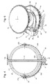
- FIGS. 3A, 3B, 3C and 4 are more detailed views of the assembly formed by the sphere 17, the support 25 and the shell 27.
- the three views 3A, 3B and 3C respectively show the shell and the support turned face, profile and three-quarter.
- the figure 4 illustrates the same set in cross section and seen from the front as in the figure 3A .
- the support 25 has the general shape of a fork with a short trunk which carries two branches 33a and 33b which extend symmetrically on either side of the sphere.
- the support 25 has an axis of symmetry which coincides with the polar axis XX of the terrestrial globe.
- the trunk of the support is constituted by a first barrel wheel (referenced 31) inside which a second barrel wheel 35 passes along with the rod 19.
- the second wheel The barrel is interposed between the rod 19 and the first gun wheel 31.
- it could be the first barrel wheel that would be placed inside the second barrel wheel.
- the two gun wheels 31, 35 and the rod 19 are free to rotate independently of each other.
- the shell 27 is pivotally mounted between the two branches 33a, 33b by means of two hinges referenced 37a and 37b and which are arranged coaxially in the extension of one another.
- the shell can therefore pivot on the support 25 along an axis of rotation that passes through the two joints.
- This pivot axis which crosses the polar axis XX in the center of the sphere 17, will be called hereinafter the ecliptic axis and referenced YY.
- Each of the two joints 37a, 37b is constituted by a pivot carried by the rim of the shell 27 and which is inserted in a bearing fixed to the end of one of the branches 33a, 33b.
- the pivots which are inserted in the two bearings occupy diametrically opposite positions on the large circle 23 constituted by the edge of the shell.
- a chain 41 connects the second cannon wheel 35 to the hinge 37a. More specifically, the chain 41 is stretched between a circular groove that the gun wheel 35 and a pinion (referenced 39) that the hinge 37a.
- the pinion 39 is fixed on the end of the pivot integral with the shell 27.
- the cannon wheel 35 constitutes the drive shaft according to the invention, and that the circular groove, the chain 41 and the pinion 39 together form the transmission means arranged to connect the drive shaft to the circle 23. In accordance with the arrangement just described, any rotation of the cannon wheel 35 relative to the support 25 is transmitted to the pinion 39 by the chain 41.
- any rotation of the barrel wheel 35 relative to the support 25 causes a corresponding pivoting of the shell 27 around the ecliptic axis YY.
- the mechanism which has just been described makes it possible to completely traverse, in one direction and then in the other, the range of values between + and -23.5 °, at the angle of inclination of the hull. 27 with respect to polar axis XX.
- the means of indicating the sunrise and sunset are capable of taking into account the effect of the variation of the inclination of the Sun over the equator according to the seasons. .
- the rim 23 of the shell also has two notches 43a and 43b arranged in diametrically opposite positions, midway between the joints 37a and 37b. It will be understood that the function of the notches 43a and 43b is to allow the passage of the rod 19 when the shell 27 is inclined relative to the polar axis XX.
- the support 25 is arranged to be driven by the movement so as to rotate at the rate of one revolution per 24 hours around the first axis X-X.
- a drive shaft coaxial with the polar axis XX is arranged to be rotated by the movement via a disengaging mechanism at the same speed as the carrier 25, but with an angular offset by report to the support.
- the drive shaft is constituted by the barrel wheel 35, and that the movement rotates the support 25 via the toothing of the barrel wheel 31.
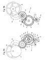
- FIG. 5A and 5B there can be seen an annual cam 56 associated with a cam follower 54.
- the cam 56 is shaped in such a way that its profile is representative of the inclination of the sun relative to the equatorial terrestrial plane.
- the cam 56 is arranged to be rotated by the movement at a rate of one revolution per year.
- the cam follower 54 is arranged to cooperate with the cam.
- the Figures 5A and 5B still show a disengaging mechanism generally referenced 50.
- the disengaging mechanism 50 is arranged to perform a transient coupling between the drive shaft and the cam follower 54, so as to allow periodically readjust the angular offset between the drive shaft (referenced 35 on the figure 4 , not shown in Figures 5A and 5B ) and the support (referenced 25 on the figures 3 and 4 , not shown on the Figures 5A and 5B ).
- the interval separating two successive transient couplings must correspond to an integer number of periods of revolution of an input mobile (referenced 70) of the clutch mechanism.
- the cam follower 54 is constituted by a rake having a toothed sector 58 and a handle which ends with a feeler 52.
- the rake is subjected to the return action of a spring (not shown) tending to apply the feeler 52 against the periphery of the annual cam 56.
- the toothed sector of the rake is arranged to mesh with a toothed wheel 68 of the clutch mechanism 50. It will be understood that the angular position of the gear wheel 68 reflects that of the cam follower. It is therefore representative of the inclination of the sun with respect to the equatorial plane.
- the disengaging mechanism 50 comprises a basic mobile comprising a wheel 70 secured to an axis 72 (visible on the Figure 5A ). It also comprises an output mobile formed of a gun wheel 74 and a toothed wheel 76 (shown only on the figure 6 ). The wheel 76 is mounted on the barrel of the barrel wheel 74. The latter is itself freely adjusted on the axis 72 of the base mobile so as to be free to rotate concentrically with the wheel 70.
- a locking clip 61 surrounds the barrel wheel 74.
- This clamp is articulated on a pivot 63 which is fixed in eccentric position on the board of the wheel 70 of the base mobile.
- a double spring 65 recalls the jaws of the locking clamp against the outside of the gun wheel 74.
- a small T-shaped lever 67 is pivoted at the base of the T on the board of the wheel 70. The small lever 67 is arranged so that a force exerted on a first end 78 of the T bar leads the other end to fit between the jaws of the clamp 61 and serve as a wedge to spread them. It will be understood that when the jaws of the locking clamp 61 are closed, the barrel wheel 74 is secured to the base mobile which then drives it in rotation.
- the output mobile is secured to the base mobile as long as no force is exerted on the end 78 of the small control lever 67. It will therefore be understood that it is not possible to modify the phase difference between the wheel 70 of the basic mobile and the wheel 76 of the mobile of output, as long as the jaws of the clamp 61 are closed around the barrel wheel 74.
- the disengaging mechanism 50 further comprises an assembly formed by a core 82 which is driven on the barrel of the barrel wheel 74 and a correction lever 84 whose end is biased against the periphery of the core by a spring 86.
- a radially referenced arm 88 is attached to the gear wheel 68. The arm 88 first radially extends beyond the toothing of the wheel 70, to then curl upwards and terminate approximately 82. The end of the arm 88 forms a small off-center support 90, and it will be understood that the function of the toothed wheel 68 with its arm 88 is that of a pivoting frame.
- the small support 90 serves both as an anchor point for the spring 86 and a pivot point for the correction lever 84. It is finally seen that the correction lever 84 carries at its end a roller and that this roller is pressed against the periphery of the core 82 by the spring 86.
- the force exerted by the roller on the core comprises a tangential component which tends to return the core towards its angular position of stable equilibrium, or in other words, towards the position where the roll is in the tick of the heart.
- the Figures 5A and 5B still show an instantaneous actuator (generally referenced 94).
- the instantaneous actuator is controlled by the movement and arranged to actuate the clutch mechanism 50 by suddenly pushing the first end 78 of the T bar of the T-shaped small lever 67.
- the instantaneous actuator 94 is already known as such. Indeed, the instantaneous actuator illustrated by the Figure 5A and 5B is described in the document EP Patent 2,503,407 entitled "watch movement comprising an instantaneous actuator controlled by the movement". This prior document is incorporated by reference.
- the instantaneous actuator 94 comprises a trailing wheel 96 driven in rotation about its axis by the movement. It will be understood that the rotational speed of the wheel 96 determines the frequency at which the instantaneous actuator actuates the disengaging mechanism.
- An advantage of using an instantaneous actuator rather than a simple dragging wheel finger is that the instantaneous actuator accurately determines when the small lever 67 is pushed back and when it is released. . Indeed, the duration of the period during which the actuator pushes the T-shaped lever is not determined by the rotational speed of the trailing wheel, but by a double trigger much faster.
- the basic mobile 70 fulfills the function of mobile entry of the clutch mechanism. It is driven by movement at the speed of one turn every 12 hours. As explained above, as long as no force is exerted on the control lever 67, the barrel wheel 74 and the core 72 are integrally connected to the wheel 70 of the base mobile. The basic mobile drives them in rotation at the rate of two revolutions per 24 hours. In accordance with what has been explained above, the instantaneous actuator 94 is arranged to press the end 78 of the small lever 67 once every 12 hours.
- the interval between two actuations is not necessarily equal to the period of rotation of the mobile entry of the disengaging mechanism. Indeed, according to other embodiments, the interval between two actuations could correspond to any integer multiple of the period of revolution of the basic mobile.
- the instantaneous actuator forces the jaws of the locking pliers 61 to open and release their pressure on the barrel wheel 74, so that the output wheel is briefly disengaged from the basic mobile.
- the barrel wheel is then free to pivot under the action of the correction lever 84 and its spring 86.
- the barrel wheel 74 then pivots until the roller of the correction lever comes to rest in the check mark. 82.
- the angular position of the output mobile at the moment when the lever stops in the ticking of the heart depends on the angular position of the small off-center support 90 which carries the correction lever 84.
- the small off-center support is fixed to the toothed wheel 68 and the latter meshes with the cam follower 54, the angular position of the core is ultimately determined by the angular position of the annual cam 56.
- the instantaneous actuator stops pressing the control lever 67 and the jaws of the clamp 61 are closed on the gun wheel 74 fixing for the next 12 hours the phase difference between the mobile basic and mobile output.
- the phase shift between the two mobiles at the instant when the clamp 61 closes on the barrel wheel 74 is determined, on the one hand, by the angular position of the annual cam 56, and secondly, by the angular position of the wheel 70 of the base mobile at this moment.
- the angular position of the wheel 70 at the instant when the locking means are closed is therefore critical for the operation of the disengaging mechanism of the present invention. This is the reason why the interval between two releases of the disengaging mechanism must correspond to an integer multiple of the period of revolution of the basic mobile.
- the output of the release mechanism 50 is arranged to drive the drive shaft via a gear train.
- the movable output of the clutch mechanism is constituted by the barrel wheel 74 and the toothed wheel 76 which is mounted on the barrel of the barrel wheel, and that the second barrel wheel 35 constitutes the drive shaft according to the invention.
- a train gear (not shown in the figures) is further provided for connecting the gear wheel 76 to the second wheel gun 35.
- This gear train can be made in any manner known to those skilled in the art. It is worth noting, however, that gearwheel 76 normally performs one revolution in 12 hours, while second gearwheel 35 is arranged to accomplish one revolution in 24 hours.
- the gear train must therefore be a reduction gear train with a gear ratio equal to 1/2.
- the polar axis (XX) is oriented parallel to the dial.
- the first and the second wheel 31, 35 are arranged in a supine position.
- the second wheel 35 and the output wheel 76 of the disengaging mechanism are perpendicular. It is therefore possible to provide in the aforementioned gear train a bevel gear to allow the connection between the toothed wheel 76 and the second cannon wheel 35.
Priority Applications (6)
| Application Number | Priority Date | Filing Date | Title |
|---|---|---|---|
| EP14187982.5A EP3007012B1 (de) | 2014-10-07 | 2014-10-07 | Uhr, die den Sonnenauf- und -untergang an jedem Punkt der Erde anzeigen kann |
| US14/862,382 US9335739B2 (en) | 2014-10-07 | 2015-09-23 | Timepiece able to indicate the sunrise or sunset anywhere in the world |
| CN201510640276.0A CN105487369B (zh) | 2014-10-07 | 2015-09-30 | 能够指示世界上任何地方的日出或日落的钟表 |
| RU2015142481A RU2015142481A (ru) | 2014-10-07 | 2015-10-06 | Часы, показывающие восход солнца или заход солнца в любой точке земного шара |
| JP2015198318A JP6067814B2 (ja) | 2014-10-07 | 2015-10-06 | 世界中全ての場所の日出又は日没を表示できる計時器 |
| HK16107512.6A HK1219544A1 (zh) | 2014-10-07 | 2016-06-28 | 能夠指示世界上任何地方的日出或日落的鐘錶 |
Applications Claiming Priority (1)
| Application Number | Priority Date | Filing Date | Title |
|---|---|---|---|
| EP14187982.5A EP3007012B1 (de) | 2014-10-07 | 2014-10-07 | Uhr, die den Sonnenauf- und -untergang an jedem Punkt der Erde anzeigen kann |
Publications (2)
| Publication Number | Publication Date |
|---|---|
| EP3007012A1 true EP3007012A1 (de) | 2016-04-13 |
| EP3007012B1 EP3007012B1 (de) | 2017-08-16 |
Family
ID=51659589
Family Applications (1)
| Application Number | Title | Priority Date | Filing Date |
|---|---|---|---|
| EP14187982.5A Active EP3007012B1 (de) | 2014-10-07 | 2014-10-07 | Uhr, die den Sonnenauf- und -untergang an jedem Punkt der Erde anzeigen kann |
Country Status (6)
| Country | Link |
|---|---|
| US (1) | US9335739B2 (de) |
| EP (1) | EP3007012B1 (de) |
| JP (1) | JP6067814B2 (de) |
| CN (1) | CN105487369B (de) |
| HK (1) | HK1219544A1 (de) |
| RU (1) | RU2015142481A (de) |
Cited By (2)
| Publication number | Priority date | Publication date | Assignee | Title |
|---|---|---|---|---|
| EP3339972A1 (de) | 2016-12-23 | 2018-06-27 | The Swatch Group Research and Development Ltd | Uhr, die mit einer tag-/nachtanzeige ausgestattet ist und die jahreszeitlichen änderungen berücksichtigt |
| EP3339971A1 (de) | 2016-12-23 | 2018-06-27 | The Swatch Group Research and Development Ltd | Uhr, die mit einer tag/nachtanzeige ausgestattet ist, die die jahreszeitlichen änderungen berücksichtigt |
Families Citing this family (3)
| Publication number | Priority date | Publication date | Assignee | Title |
|---|---|---|---|---|
| CH713581A2 (fr) * | 2017-03-17 | 2018-09-28 | Montres Jaquet Droz Sa | Pièce d'horlogerie comprenant un automate capable de reproduire des battements d'ailes. |
| EP3410232B1 (de) * | 2017-05-29 | 2021-07-21 | Montres Breguet S.A. | Uhrwerksmechanismus |
| JP1625435S (de) * | 2018-02-02 | 2019-02-25 |
Citations (6)
| Publication number | Priority date | Publication date | Assignee | Title |
|---|---|---|---|---|
| DE7014354U (de) | 1970-04-18 | 1970-11-05 | Koch W | Welt- und jahreszeituhr |
| JP2001290418A (ja) * | 2000-04-07 | 2001-10-19 | Tetsuzo Shibuya | 地球儀 |
| US20020131329A1 (en) * | 1999-12-23 | 2002-09-19 | Ochoa Loaiza Miguel Guillermo | World globe pocket clock and world globe desk clock |
| WO2002082191A1 (de) * | 2001-04-05 | 2002-10-17 | Egino Riedl | Weltzeituhr |
| EP2503407A2 (de) | 2011-03-23 | 2012-09-26 | Montres Breguet SA | Uhrwerk, das einen über die Bewegung gesteuerten Schnellauslöser umfasst |
| CH705722A1 (fr) * | 2011-11-02 | 2013-05-15 | Gfpi S A | Pièce d'horlogerie. |
Family Cites Families (13)
| Publication number | Priority date | Publication date | Assignee | Title |
|---|---|---|---|---|
| JPS54103133A (en) * | 1978-01-30 | 1979-08-14 | Yukio Riyuuraku | Globe with timepiece |
| JPS5978990U (ja) * | 1982-11-18 | 1984-05-28 | トヨタ自動車株式会社 | 季節時計 |
| FR2590058B1 (fr) * | 1985-09-27 | 1989-12-01 | Domen Jean Paul | Perfectionnements aux globes terrestres |
| FR2615297B1 (fr) * | 1987-05-12 | 1990-11-30 | Vuarnesson Bernard | Appareil reproduisant la vision apparente des astres |
| CN2078895U (zh) * | 1990-11-13 | 1991-06-12 | 陈咸珣 | 晨昏仪 |
| US5280458A (en) * | 1992-12-18 | 1994-01-18 | Scott Craig S | Sunlit world globe |
| WO1998001795A1 (fr) * | 1996-07-05 | 1998-01-15 | Edouard Pfister | Dispositif horometrique |
| US7012855B1 (en) * | 1999-12-23 | 2006-03-14 | Miguel Guillermo Ochoa Loaiza | World globe pocket clock and world globe desk clock |
| EP1349020A1 (de) * | 2002-03-28 | 2003-10-01 | Manufacture Roger Dubuis S.A. | Uhr mit Kalender |
| JP2006220509A (ja) * | 2005-02-09 | 2006-08-24 | Hironori Yagi | 時計表示装置 |
| CN101281387A (zh) * | 2007-09-07 | 2008-10-08 | 马庆华 | 钟表 |
| EP2911013B1 (de) * | 2014-02-20 | 2017-04-05 | The Swatch Group Research and Development Ltd. | Uhr, die den Sonnenauf- und -untergang an jedem Punkt der Erde anzeigen kann |
| EP2977832B1 (de) * | 2014-07-23 | 2017-08-30 | The Swatch Group Research and Development Ltd. | Uhr, die den sonnenauf oder den untergang an jedem punkt der erde anzeigen kann |
-
2014
- 2014-10-07 EP EP14187982.5A patent/EP3007012B1/de active Active
-
2015
- 2015-09-23 US US14/862,382 patent/US9335739B2/en active Active
- 2015-09-30 CN CN201510640276.0A patent/CN105487369B/zh active Active
- 2015-10-06 RU RU2015142481A patent/RU2015142481A/ru not_active Application Discontinuation
- 2015-10-06 JP JP2015198318A patent/JP6067814B2/ja active Active
-
2016
- 2016-06-28 HK HK16107512.6A patent/HK1219544A1/zh unknown
Patent Citations (6)
| Publication number | Priority date | Publication date | Assignee | Title |
|---|---|---|---|---|
| DE7014354U (de) | 1970-04-18 | 1970-11-05 | Koch W | Welt- und jahreszeituhr |
| US20020131329A1 (en) * | 1999-12-23 | 2002-09-19 | Ochoa Loaiza Miguel Guillermo | World globe pocket clock and world globe desk clock |
| JP2001290418A (ja) * | 2000-04-07 | 2001-10-19 | Tetsuzo Shibuya | 地球儀 |
| WO2002082191A1 (de) * | 2001-04-05 | 2002-10-17 | Egino Riedl | Weltzeituhr |
| EP2503407A2 (de) | 2011-03-23 | 2012-09-26 | Montres Breguet SA | Uhrwerk, das einen über die Bewegung gesteuerten Schnellauslöser umfasst |
| CH705722A1 (fr) * | 2011-11-02 | 2013-05-15 | Gfpi S A | Pièce d'horlogerie. |
Cited By (3)
| Publication number | Priority date | Publication date | Assignee | Title |
|---|---|---|---|---|
| EP3339972A1 (de) | 2016-12-23 | 2018-06-27 | The Swatch Group Research and Development Ltd | Uhr, die mit einer tag-/nachtanzeige ausgestattet ist und die jahreszeitlichen änderungen berücksichtigt |
| EP3339971A1 (de) | 2016-12-23 | 2018-06-27 | The Swatch Group Research and Development Ltd | Uhr, die mit einer tag/nachtanzeige ausgestattet ist, die die jahreszeitlichen änderungen berücksichtigt |
| US10775745B2 (en) | 2016-12-23 | 2020-09-15 | The Swatch Group Research And Development Ltd | Timepiece comprising a day/night display that takes account of seasonal variations |
Also Published As
| Publication number | Publication date |
|---|---|
| HK1219544A1 (zh) | 2017-04-07 |
| CN105487369B (zh) | 2018-01-26 |
| RU2015142481A (ru) | 2017-04-10 |
| EP3007012B1 (de) | 2017-08-16 |
| US9335739B2 (en) | 2016-05-10 |
| CN105487369A (zh) | 2016-04-13 |
| US20160098012A1 (en) | 2016-04-07 |
| JP6067814B2 (ja) | 2017-01-25 |
| JP2016075685A (ja) | 2016-05-12 |
Similar Documents
| Publication | Publication Date | Title |
|---|---|---|
| EP2977832B1 (de) | Uhr, die den sonnenauf oder den untergang an jedem punkt der erde anzeigen kann | |
| EP2911013B1 (de) | Uhr, die den Sonnenauf- und -untergang an jedem Punkt der Erde anzeigen kann | |
| EP3007012B1 (de) | Uhr, die den Sonnenauf- und -untergang an jedem Punkt der Erde anzeigen kann | |
| EP2012199B1 (de) | Uhr, die mit einer Vorrichtung zur Steuerung von Funktionen und/oder Stundenanzeigen ausgerüstet ist | |
| EP3483664B1 (de) | Uhrmechanismus zum anzeigen des mondtags und der mondphase mit korrektursystem mit doppeltem antriebsstrang | |
| EP3008523B1 (de) | Kalendermechanismus für ein uhrwerk | |
| EP3477402B1 (de) | Mondphasen-anzeigevorrichtung | |
| EP1286233A1 (de) | Kalenderuhr mit Äquationsvorrichtung | |
| FR2657439A1 (fr) | Dispositif de representation de la lune, notamment sur le cadran d'une montre. | |
| CH710217A2 (fr) | Pièce d'horlogerie pouvant indiquer le lever ou le coucher du soleil en tout point du globe. | |
| EP3339971B1 (de) | Uhr, die mit einer tag/nachtanzeige ausgestattet ist, die die jahreszeitlichen änderungen berücksichtigt | |
| CH706094B1 (fr) | Dispositif d'affichage de phases de lune. | |
| EP2853957A1 (de) | Mondphasen-Anzeigevorrichtung | |
| EP3460588B1 (de) | Datumsmechanismus | |
| EP3339972B1 (de) | Uhr, die mit einer tag-/nachtanzeige ausgestattet ist und die jahreszeitlichen änderungen berücksichtigt | |
| CH709947B1 (fr) | Pièce d'horlogerie indiquant le lever et le coucher du Soleil en tout point du globe. | |
| CH705128B1 (fr) | Dispositif d'affichage du quantième et de la phase de lune. | |
| EP3048494A2 (de) | Organ zum aufziehen und/oder zur zeiteinstellung zur steuerung eines uhrwerk, und armbanduhr, die dieses organ umfasst | |
| EP2993532A2 (de) | Antriebsmechanismus mindestens eines beweglichen elements | |
| CH713331A2 (fr) | Pièce d'horlogerie comportant un affichage jour/nuit tenant compte des variations saisonnières. | |
| EP1353244B1 (de) | Uhr mit länglichem Gehäuse | |
| CH713284A2 (fr) | Pièce d'horlogerie comportant un affichage jour/nuit tenant compte des variations saisonnières. | |
| EP3330807B1 (de) | Vorrichtung zur alternativen anzeige | |
| CH709290A2 (fr) | Pièce d'horlogerie pouvant indiquer le lever ou le coucher du soleil en tout point du globe. | |
| CH714320A2 (fr) | Mécanisme horloger d'affichage du jour lunaire et de la phase de lune, avec système de correction à double chaîne cinématique. |
Legal Events
| Date | Code | Title | Description |
|---|---|---|---|
| PUAI | Public reference made under article 153(3) epc to a published international application that has entered the european phase |
Free format text: ORIGINAL CODE: 0009012 |
|
| AK | Designated contracting states |
Kind code of ref document: A1 Designated state(s): AL AT BE BG CH CY CZ DE DK EE ES FI FR GB GR HR HU IE IS IT LI LT LU LV MC MK MT NL NO PL PT RO RS SE SI SK SM TR |
|
| AX | Request for extension of the european patent |
Extension state: BA ME |
|
| 17P | Request for examination filed |
Effective date: 20161013 |
|
| RBV | Designated contracting states (corrected) |
Designated state(s): AL AT BE BG CH CY CZ DE DK EE ES FI FR GB GR HR HU IE IS IT LI LT LU LV MC MK MT NL NO PL PT RO RS SE SI SK SM TR |
|
| GRAP | Despatch of communication of intention to grant a patent |
Free format text: ORIGINAL CODE: EPIDOSNIGR1 |
|
| RIC1 | Information provided on ipc code assigned before grant |
Ipc: G04B 19/26 20060101ALI20170407BHEP Ipc: G04B 19/22 20060101AFI20170407BHEP |
|
| INTG | Intention to grant announced |
Effective date: 20170509 |
|
| GRAS | Grant fee paid |
Free format text: ORIGINAL CODE: EPIDOSNIGR3 |
|
| GRAA | (expected) grant |
Free format text: ORIGINAL CODE: 0009210 |
|
| AK | Designated contracting states |
Kind code of ref document: B1 Designated state(s): AL AT BE BG CH CY CZ DE DK EE ES FI FR GB GR HR HU IE IS IT LI LT LU LV MC MK MT NL NO PL PT RO RS SE SI SK SM TR |
|
| REG | Reference to a national code |
Ref country code: GB Ref legal event code: FG4D Free format text: NOT ENGLISH |
|
| REG | Reference to a national code |
Ref country code: CH Ref legal event code: EP Ref country code: CH Ref legal event code: NV Representative=s name: ICB INGENIEURS CONSEILS EN BREVETS SA, CH |
|
| REG | Reference to a national code |
Ref country code: IE Ref legal event code: FG4D Free format text: LANGUAGE OF EP DOCUMENT: FRENCH |
|
| REG | Reference to a national code |
Ref country code: AT Ref legal event code: REF Ref document number: 919641 Country of ref document: AT Kind code of ref document: T Effective date: 20170915 |
|
| REG | Reference to a national code |
Ref country code: DE Ref legal event code: R096 Ref document number: 602014013129 Country of ref document: DE |
|
| REG | Reference to a national code |
Ref country code: FR Ref legal event code: PLFP Year of fee payment: 4 |
|
| REG | Reference to a national code |
Ref country code: NL Ref legal event code: MP Effective date: 20170816 |
|
| REG | Reference to a national code |
Ref country code: LT Ref legal event code: MG4D |
|
| REG | Reference to a national code |
Ref country code: AT Ref legal event code: MK05 Ref document number: 919641 Country of ref document: AT Kind code of ref document: T Effective date: 20170816 |
|
| PG25 | Lapsed in a contracting state [announced via postgrant information from national office to epo] |
Ref country code: SE Free format text: LAPSE BECAUSE OF FAILURE TO SUBMIT A TRANSLATION OF THE DESCRIPTION OR TO PAY THE FEE WITHIN THE PRESCRIBED TIME-LIMIT Effective date: 20170816 Ref country code: NL Free format text: LAPSE BECAUSE OF FAILURE TO SUBMIT A TRANSLATION OF THE DESCRIPTION OR TO PAY THE FEE WITHIN THE PRESCRIBED TIME-LIMIT Effective date: 20170816 Ref country code: LT Free format text: LAPSE BECAUSE OF FAILURE TO SUBMIT A TRANSLATION OF THE DESCRIPTION OR TO PAY THE FEE WITHIN THE PRESCRIBED TIME-LIMIT Effective date: 20170816 Ref country code: FI Free format text: LAPSE BECAUSE OF FAILURE TO SUBMIT A TRANSLATION OF THE DESCRIPTION OR TO PAY THE FEE WITHIN THE PRESCRIBED TIME-LIMIT Effective date: 20170816 Ref country code: AT Free format text: LAPSE BECAUSE OF FAILURE TO SUBMIT A TRANSLATION OF THE DESCRIPTION OR TO PAY THE FEE WITHIN THE PRESCRIBED TIME-LIMIT Effective date: 20170816 Ref country code: NO Free format text: LAPSE BECAUSE OF FAILURE TO SUBMIT A TRANSLATION OF THE DESCRIPTION OR TO PAY THE FEE WITHIN THE PRESCRIBED TIME-LIMIT Effective date: 20171116 |
|
| PG25 | Lapsed in a contracting state [announced via postgrant information from national office to epo] |
Ref country code: ES Free format text: LAPSE BECAUSE OF FAILURE TO SUBMIT A TRANSLATION OF THE DESCRIPTION OR TO PAY THE FEE WITHIN THE PRESCRIBED TIME-LIMIT Effective date: 20170816 Ref country code: BG Free format text: LAPSE BECAUSE OF FAILURE TO SUBMIT A TRANSLATION OF THE DESCRIPTION OR TO PAY THE FEE WITHIN THE PRESCRIBED TIME-LIMIT Effective date: 20171116 Ref country code: RS Free format text: LAPSE BECAUSE OF FAILURE TO SUBMIT A TRANSLATION OF THE DESCRIPTION OR TO PAY THE FEE WITHIN THE PRESCRIBED TIME-LIMIT Effective date: 20170816 Ref country code: GR Free format text: LAPSE BECAUSE OF FAILURE TO SUBMIT A TRANSLATION OF THE DESCRIPTION OR TO PAY THE FEE WITHIN THE PRESCRIBED TIME-LIMIT Effective date: 20171117 Ref country code: IS Free format text: LAPSE BECAUSE OF FAILURE TO SUBMIT A TRANSLATION OF THE DESCRIPTION OR TO PAY THE FEE WITHIN THE PRESCRIBED TIME-LIMIT Effective date: 20171216 Ref country code: LV Free format text: LAPSE BECAUSE OF FAILURE TO SUBMIT A TRANSLATION OF THE DESCRIPTION OR TO PAY THE FEE WITHIN THE PRESCRIBED TIME-LIMIT Effective date: 20170816 Ref country code: PL Free format text: LAPSE BECAUSE OF FAILURE TO SUBMIT A TRANSLATION OF THE DESCRIPTION OR TO PAY THE FEE WITHIN THE PRESCRIBED TIME-LIMIT Effective date: 20170816 |
|
| PG25 | Lapsed in a contracting state [announced via postgrant information from national office to epo] |
Ref country code: DK Free format text: LAPSE BECAUSE OF FAILURE TO SUBMIT A TRANSLATION OF THE DESCRIPTION OR TO PAY THE FEE WITHIN THE PRESCRIBED TIME-LIMIT Effective date: 20170816 Ref country code: CZ Free format text: LAPSE BECAUSE OF FAILURE TO SUBMIT A TRANSLATION OF THE DESCRIPTION OR TO PAY THE FEE WITHIN THE PRESCRIBED TIME-LIMIT Effective date: 20170816 Ref country code: RO Free format text: LAPSE BECAUSE OF FAILURE TO SUBMIT A TRANSLATION OF THE DESCRIPTION OR TO PAY THE FEE WITHIN THE PRESCRIBED TIME-LIMIT Effective date: 20170816 |
|
| REG | Reference to a national code |
Ref country code: DE Ref legal event code: R097 Ref document number: 602014013129 Country of ref document: DE |
|
| PG25 | Lapsed in a contracting state [announced via postgrant information from national office to epo] |
Ref country code: EE Free format text: LAPSE BECAUSE OF FAILURE TO SUBMIT A TRANSLATION OF THE DESCRIPTION OR TO PAY THE FEE WITHIN THE PRESCRIBED TIME-LIMIT Effective date: 20170816 Ref country code: MC Free format text: LAPSE BECAUSE OF FAILURE TO SUBMIT A TRANSLATION OF THE DESCRIPTION OR TO PAY THE FEE WITHIN THE PRESCRIBED TIME-LIMIT Effective date: 20170816 Ref country code: IT Free format text: LAPSE BECAUSE OF FAILURE TO SUBMIT A TRANSLATION OF THE DESCRIPTION OR TO PAY THE FEE WITHIN THE PRESCRIBED TIME-LIMIT Effective date: 20170816 Ref country code: SM Free format text: LAPSE BECAUSE OF FAILURE TO SUBMIT A TRANSLATION OF THE DESCRIPTION OR TO PAY THE FEE WITHIN THE PRESCRIBED TIME-LIMIT Effective date: 20170816 Ref country code: SK Free format text: LAPSE BECAUSE OF FAILURE TO SUBMIT A TRANSLATION OF THE DESCRIPTION OR TO PAY THE FEE WITHIN THE PRESCRIBED TIME-LIMIT Effective date: 20170816 |
|
| PLBE | No opposition filed within time limit |
Free format text: ORIGINAL CODE: 0009261 |
|
| STAA | Information on the status of an ep patent application or granted ep patent |
Free format text: STATUS: NO OPPOSITION FILED WITHIN TIME LIMIT |
|
| 26N | No opposition filed |
Effective date: 20180517 |
|
| REG | Reference to a national code |
Ref country code: IE Ref legal event code: MM4A |
|
| PG25 | Lapsed in a contracting state [announced via postgrant information from national office to epo] |
Ref country code: LU Free format text: LAPSE BECAUSE OF NON-PAYMENT OF DUE FEES Effective date: 20171007 |
|
| REG | Reference to a national code |
Ref country code: BE Ref legal event code: MM Effective date: 20171031 |
|
| PG25 | Lapsed in a contracting state [announced via postgrant information from national office to epo] |
Ref country code: BE Free format text: LAPSE BECAUSE OF NON-PAYMENT OF DUE FEES Effective date: 20171031 Ref country code: SI Free format text: LAPSE BECAUSE OF FAILURE TO SUBMIT A TRANSLATION OF THE DESCRIPTION OR TO PAY THE FEE WITHIN THE PRESCRIBED TIME-LIMIT Effective date: 20170816 |
|
| REG | Reference to a national code |
Ref country code: FR Ref legal event code: PLFP Year of fee payment: 5 |
|
| PG25 | Lapsed in a contracting state [announced via postgrant information from national office to epo] |
Ref country code: MT Free format text: LAPSE BECAUSE OF FAILURE TO SUBMIT A TRANSLATION OF THE DESCRIPTION OR TO PAY THE FEE WITHIN THE PRESCRIBED TIME-LIMIT Effective date: 20170816 |
|
| PG25 | Lapsed in a contracting state [announced via postgrant information from national office to epo] |
Ref country code: IE Free format text: LAPSE BECAUSE OF NON-PAYMENT OF DUE FEES Effective date: 20171007 |
|
| PG25 | Lapsed in a contracting state [announced via postgrant information from national office to epo] |
Ref country code: HU Free format text: LAPSE BECAUSE OF FAILURE TO SUBMIT A TRANSLATION OF THE DESCRIPTION OR TO PAY THE FEE WITHIN THE PRESCRIBED TIME-LIMIT; INVALID AB INITIO Effective date: 20141007 |
|
| PG25 | Lapsed in a contracting state [announced via postgrant information from national office to epo] |
Ref country code: CY Free format text: LAPSE BECAUSE OF FAILURE TO SUBMIT A TRANSLATION OF THE DESCRIPTION OR TO PAY THE FEE WITHIN THE PRESCRIBED TIME-LIMIT Effective date: 20170816 |
|
| PG25 | Lapsed in a contracting state [announced via postgrant information from national office to epo] |
Ref country code: MK Free format text: LAPSE BECAUSE OF FAILURE TO SUBMIT A TRANSLATION OF THE DESCRIPTION OR TO PAY THE FEE WITHIN THE PRESCRIBED TIME-LIMIT Effective date: 20170816 |
|
| PG25 | Lapsed in a contracting state [announced via postgrant information from national office to epo] |
Ref country code: TR Free format text: LAPSE BECAUSE OF FAILURE TO SUBMIT A TRANSLATION OF THE DESCRIPTION OR TO PAY THE FEE WITHIN THE PRESCRIBED TIME-LIMIT Effective date: 20170816 |
|
| PG25 | Lapsed in a contracting state [announced via postgrant information from national office to epo] |
Ref country code: PT Free format text: LAPSE BECAUSE OF FAILURE TO SUBMIT A TRANSLATION OF THE DESCRIPTION OR TO PAY THE FEE WITHIN THE PRESCRIBED TIME-LIMIT Effective date: 20170816 |
|
| PG25 | Lapsed in a contracting state [announced via postgrant information from national office to epo] |
Ref country code: HR Free format text: LAPSE BECAUSE OF FAILURE TO SUBMIT A TRANSLATION OF THE DESCRIPTION OR TO PAY THE FEE WITHIN THE PRESCRIBED TIME-LIMIT Effective date: 20170816 |
|
| PG25 | Lapsed in a contracting state [announced via postgrant information from national office to epo] |
Ref country code: AL Free format text: LAPSE BECAUSE OF FAILURE TO SUBMIT A TRANSLATION OF THE DESCRIPTION OR TO PAY THE FEE WITHIN THE PRESCRIBED TIME-LIMIT Effective date: 20170816 |
|
| P01 | Opt-out of the competence of the unified patent court (upc) registered |
Effective date: 20230615 |
|
| PGFP | Annual fee paid to national office [announced via postgrant information from national office to epo] |
Ref country code: GB Payment date: 20230920 Year of fee payment: 10 |
|
| PGFP | Annual fee paid to national office [announced via postgrant information from national office to epo] |
Ref country code: FR Payment date: 20230920 Year of fee payment: 10 |
|
| PGFP | Annual fee paid to national office [announced via postgrant information from national office to epo] |
Ref country code: DE Payment date: 20230920 Year of fee payment: 10 Ref country code: CH Payment date: 20231102 Year of fee payment: 10 |