EP3006805B1 - Schlauchliner für die kanalsanierung - Google Patents
Schlauchliner für die kanalsanierung Download PDFInfo
- Publication number
- EP3006805B1 EP3006805B1 EP15188733.8A EP15188733A EP3006805B1 EP 3006805 B1 EP3006805 B1 EP 3006805B1 EP 15188733 A EP15188733 A EP 15188733A EP 3006805 B1 EP3006805 B1 EP 3006805B1
- Authority
- EP
- European Patent Office
- Prior art keywords
- film
- tubular liner
- resin
- outer film
- layer
- Prior art date
- Legal status (The legal status is an assumption and is not a legal conclusion. Google has not performed a legal analysis and makes no representation as to the accuracy of the status listed.)
- Active
Links
Images


Classifications
-
- F—MECHANICAL ENGINEERING; LIGHTING; HEATING; WEAPONS; BLASTING
- F16—ENGINEERING ELEMENTS AND UNITS; GENERAL MEASURES FOR PRODUCING AND MAINTAINING EFFECTIVE FUNCTIONING OF MACHINES OR INSTALLATIONS; THERMAL INSULATION IN GENERAL
- F16L—PIPES; JOINTS OR FITTINGS FOR PIPES; SUPPORTS FOR PIPES, CABLES OR PROTECTIVE TUBING; MEANS FOR THERMAL INSULATION IN GENERAL
- F16L55/00—Devices or appurtenances for use in, or in connection with, pipes or pipe systems
- F16L55/16—Devices for covering leaks in pipes or hoses, e.g. hose-menders
- F16L55/162—Devices for covering leaks in pipes or hoses, e.g. hose-menders from inside the pipe
- F16L55/165—Devices for covering leaks in pipes or hoses, e.g. hose-menders from inside the pipe a pipe or flexible liner being inserted in the damaged section
- F16L55/1656—Devices for covering leaks in pipes or hoses, e.g. hose-menders from inside the pipe a pipe or flexible liner being inserted in the damaged section materials for flexible liners
-
- B—PERFORMING OPERATIONS; TRANSPORTING
- B29—WORKING OF PLASTICS; WORKING OF SUBSTANCES IN A PLASTIC STATE IN GENERAL
- B29C—SHAPING OR JOINING OF PLASTICS; SHAPING OF MATERIAL IN A PLASTIC STATE, NOT OTHERWISE PROVIDED FOR; AFTER-TREATMENT OF THE SHAPED PRODUCTS, e.g. REPAIRING
- B29C63/00—Lining or sheathing, i.e. applying preformed layers or sheathings of plastics; Apparatus therefor
- B29C63/02—Lining or sheathing, i.e. applying preformed layers or sheathings of plastics; Apparatus therefor using sheet or web-like material
- B29C63/04—Lining or sheathing, i.e. applying preformed layers or sheathings of plastics; Apparatus therefor using sheet or web-like material by folding, winding, bending or the like
- B29C63/06—Lining or sheathing, i.e. applying preformed layers or sheathings of plastics; Apparatus therefor using sheet or web-like material by folding, winding, bending or the like around tubular articles
-
- B—PERFORMING OPERATIONS; TRANSPORTING
- B32—LAYERED PRODUCTS
- B32B—LAYERED PRODUCTS, i.e. PRODUCTS BUILT-UP OF STRATA OF FLAT OR NON-FLAT, e.g. CELLULAR OR HONEYCOMB, FORM
- B32B1/00—Layered products having a non-planar shape
- B32B1/08—Tubular products
-
- B—PERFORMING OPERATIONS; TRANSPORTING
- B32—LAYERED PRODUCTS
- B32B—LAYERED PRODUCTS, i.e. PRODUCTS BUILT-UP OF STRATA OF FLAT OR NON-FLAT, e.g. CELLULAR OR HONEYCOMB, FORM
- B32B25/00—Layered products comprising a layer of natural or synthetic rubber
- B32B25/04—Layered products comprising a layer of natural or synthetic rubber comprising rubber as the main or only constituent of a layer, which is next to another layer of the same or of a different material
- B32B25/042—Layered products comprising a layer of natural or synthetic rubber comprising rubber as the main or only constituent of a layer, which is next to another layer of the same or of a different material of natural rubber or synthetic rubber
-
- B—PERFORMING OPERATIONS; TRANSPORTING
- B32—LAYERED PRODUCTS
- B32B—LAYERED PRODUCTS, i.e. PRODUCTS BUILT-UP OF STRATA OF FLAT OR NON-FLAT, e.g. CELLULAR OR HONEYCOMB, FORM
- B32B25/00—Layered products comprising a layer of natural or synthetic rubber
- B32B25/04—Layered products comprising a layer of natural or synthetic rubber comprising rubber as the main or only constituent of a layer, which is next to another layer of the same or of a different material
- B32B25/08—Layered products comprising a layer of natural or synthetic rubber comprising rubber as the main or only constituent of a layer, which is next to another layer of the same or of a different material of synthetic resin
-
- B—PERFORMING OPERATIONS; TRANSPORTING
- B32—LAYERED PRODUCTS
- B32B—LAYERED PRODUCTS, i.e. PRODUCTS BUILT-UP OF STRATA OF FLAT OR NON-FLAT, e.g. CELLULAR OR HONEYCOMB, FORM
- B32B25/00—Layered products comprising a layer of natural or synthetic rubber
- B32B25/10—Layered products comprising a layer of natural or synthetic rubber next to a fibrous or filamentary layer
-
- B—PERFORMING OPERATIONS; TRANSPORTING
- B32—LAYERED PRODUCTS
- B32B—LAYERED PRODUCTS, i.e. PRODUCTS BUILT-UP OF STRATA OF FLAT OR NON-FLAT, e.g. CELLULAR OR HONEYCOMB, FORM
- B32B25/00—Layered products comprising a layer of natural or synthetic rubber
- B32B25/14—Layered products comprising a layer of natural or synthetic rubber comprising synthetic rubber copolymers
-
- B—PERFORMING OPERATIONS; TRANSPORTING
- B32—LAYERED PRODUCTS
- B32B—LAYERED PRODUCTS, i.e. PRODUCTS BUILT-UP OF STRATA OF FLAT OR NON-FLAT, e.g. CELLULAR OR HONEYCOMB, FORM
- B32B27/00—Layered products comprising a layer of synthetic resin
- B32B27/06—Layered products comprising a layer of synthetic resin as the main or only constituent of a layer, which is next to another layer of the same or of a different material
- B32B27/08—Layered products comprising a layer of synthetic resin as the main or only constituent of a layer, which is next to another layer of the same or of a different material of synthetic resin
-
- B—PERFORMING OPERATIONS; TRANSPORTING
- B32—LAYERED PRODUCTS
- B32B—LAYERED PRODUCTS, i.e. PRODUCTS BUILT-UP OF STRATA OF FLAT OR NON-FLAT, e.g. CELLULAR OR HONEYCOMB, FORM
- B32B27/00—Layered products comprising a layer of synthetic resin
- B32B27/12—Layered products comprising a layer of synthetic resin next to a fibrous or filamentary layer
-
- B—PERFORMING OPERATIONS; TRANSPORTING
- B32—LAYERED PRODUCTS
- B32B—LAYERED PRODUCTS, i.e. PRODUCTS BUILT-UP OF STRATA OF FLAT OR NON-FLAT, e.g. CELLULAR OR HONEYCOMB, FORM
- B32B27/00—Layered products comprising a layer of synthetic resin
- B32B27/30—Layered products comprising a layer of synthetic resin comprising vinyl (co)polymers; comprising acrylic (co)polymers
- B32B27/302—Layered products comprising a layer of synthetic resin comprising vinyl (co)polymers; comprising acrylic (co)polymers comprising aromatic vinyl (co)polymers, e.g. styrenic (co)polymers
-
- B—PERFORMING OPERATIONS; TRANSPORTING
- B32—LAYERED PRODUCTS
- B32B—LAYERED PRODUCTS, i.e. PRODUCTS BUILT-UP OF STRATA OF FLAT OR NON-FLAT, e.g. CELLULAR OR HONEYCOMB, FORM
- B32B27/00—Layered products comprising a layer of synthetic resin
- B32B27/30—Layered products comprising a layer of synthetic resin comprising vinyl (co)polymers; comprising acrylic (co)polymers
- B32B27/304—Layered products comprising a layer of synthetic resin comprising vinyl (co)polymers; comprising acrylic (co)polymers comprising vinyl halide (co)polymers, e.g. PVC, PVDC, PVF, PVDF
-
- B—PERFORMING OPERATIONS; TRANSPORTING
- B32—LAYERED PRODUCTS
- B32B—LAYERED PRODUCTS, i.e. PRODUCTS BUILT-UP OF STRATA OF FLAT OR NON-FLAT, e.g. CELLULAR OR HONEYCOMB, FORM
- B32B27/00—Layered products comprising a layer of synthetic resin
- B32B27/30—Layered products comprising a layer of synthetic resin comprising vinyl (co)polymers; comprising acrylic (co)polymers
- B32B27/306—Layered products comprising a layer of synthetic resin comprising vinyl (co)polymers; comprising acrylic (co)polymers comprising vinyl acetate or vinyl alcohol (co)polymers
-
- B—PERFORMING OPERATIONS; TRANSPORTING
- B32—LAYERED PRODUCTS
- B32B—LAYERED PRODUCTS, i.e. PRODUCTS BUILT-UP OF STRATA OF FLAT OR NON-FLAT, e.g. CELLULAR OR HONEYCOMB, FORM
- B32B27/00—Layered products comprising a layer of synthetic resin
- B32B27/30—Layered products comprising a layer of synthetic resin comprising vinyl (co)polymers; comprising acrylic (co)polymers
- B32B27/308—Layered products comprising a layer of synthetic resin comprising vinyl (co)polymers; comprising acrylic (co)polymers comprising acrylic (co)polymers
-
- B—PERFORMING OPERATIONS; TRANSPORTING
- B32—LAYERED PRODUCTS
- B32B—LAYERED PRODUCTS, i.e. PRODUCTS BUILT-UP OF STRATA OF FLAT OR NON-FLAT, e.g. CELLULAR OR HONEYCOMB, FORM
- B32B27/00—Layered products comprising a layer of synthetic resin
- B32B27/32—Layered products comprising a layer of synthetic resin comprising polyolefins
-
- B—PERFORMING OPERATIONS; TRANSPORTING
- B32—LAYERED PRODUCTS
- B32B—LAYERED PRODUCTS, i.e. PRODUCTS BUILT-UP OF STRATA OF FLAT OR NON-FLAT, e.g. CELLULAR OR HONEYCOMB, FORM
- B32B27/00—Layered products comprising a layer of synthetic resin
- B32B27/34—Layered products comprising a layer of synthetic resin comprising polyamides
-
- B—PERFORMING OPERATIONS; TRANSPORTING
- B32—LAYERED PRODUCTS
- B32B—LAYERED PRODUCTS, i.e. PRODUCTS BUILT-UP OF STRATA OF FLAT OR NON-FLAT, e.g. CELLULAR OR HONEYCOMB, FORM
- B32B27/00—Layered products comprising a layer of synthetic resin
- B32B27/36—Layered products comprising a layer of synthetic resin comprising polyesters
-
- B—PERFORMING OPERATIONS; TRANSPORTING
- B32—LAYERED PRODUCTS
- B32B—LAYERED PRODUCTS, i.e. PRODUCTS BUILT-UP OF STRATA OF FLAT OR NON-FLAT, e.g. CELLULAR OR HONEYCOMB, FORM
- B32B27/00—Layered products comprising a layer of synthetic resin
- B32B27/36—Layered products comprising a layer of synthetic resin comprising polyesters
- B32B27/365—Layered products comprising a layer of synthetic resin comprising polyesters comprising polycarbonates
-
- B—PERFORMING OPERATIONS; TRANSPORTING
- B32—LAYERED PRODUCTS
- B32B—LAYERED PRODUCTS, i.e. PRODUCTS BUILT-UP OF STRATA OF FLAT OR NON-FLAT, e.g. CELLULAR OR HONEYCOMB, FORM
- B32B5/00—Layered products characterised by the non- homogeneity or physical structure, i.e. comprising a fibrous, filamentary, particulate or foam layer; Layered products characterised by having a layer differing constitutionally or physically in different parts
- B32B5/02—Layered products characterised by the non- homogeneity or physical structure, i.e. comprising a fibrous, filamentary, particulate or foam layer; Layered products characterised by having a layer differing constitutionally or physically in different parts characterised by structural features of a fibrous or filamentary layer
-
- B—PERFORMING OPERATIONS; TRANSPORTING
- B32—LAYERED PRODUCTS
- B32B—LAYERED PRODUCTS, i.e. PRODUCTS BUILT-UP OF STRATA OF FLAT OR NON-FLAT, e.g. CELLULAR OR HONEYCOMB, FORM
- B32B5/00—Layered products characterised by the non- homogeneity or physical structure, i.e. comprising a fibrous, filamentary, particulate or foam layer; Layered products characterised by having a layer differing constitutionally or physically in different parts
- B32B5/02—Layered products characterised by the non- homogeneity or physical structure, i.e. comprising a fibrous, filamentary, particulate or foam layer; Layered products characterised by having a layer differing constitutionally or physically in different parts characterised by structural features of a fibrous or filamentary layer
- B32B5/022—Non-woven fabric
-
- B—PERFORMING OPERATIONS; TRANSPORTING
- B32—LAYERED PRODUCTS
- B32B—LAYERED PRODUCTS, i.e. PRODUCTS BUILT-UP OF STRATA OF FLAT OR NON-FLAT, e.g. CELLULAR OR HONEYCOMB, FORM
- B32B5/00—Layered products characterised by the non- homogeneity or physical structure, i.e. comprising a fibrous, filamentary, particulate or foam layer; Layered products characterised by having a layer differing constitutionally or physically in different parts
- B32B5/02—Layered products characterised by the non- homogeneity or physical structure, i.e. comprising a fibrous, filamentary, particulate or foam layer; Layered products characterised by having a layer differing constitutionally or physically in different parts characterised by structural features of a fibrous or filamentary layer
- B32B5/024—Woven fabric
-
- B—PERFORMING OPERATIONS; TRANSPORTING
- B32—LAYERED PRODUCTS
- B32B—LAYERED PRODUCTS, i.e. PRODUCTS BUILT-UP OF STRATA OF FLAT OR NON-FLAT, e.g. CELLULAR OR HONEYCOMB, FORM
- B32B5/00—Layered products characterised by the non- homogeneity or physical structure, i.e. comprising a fibrous, filamentary, particulate or foam layer; Layered products characterised by having a layer differing constitutionally or physically in different parts
- B32B5/02—Layered products characterised by the non- homogeneity or physical structure, i.e. comprising a fibrous, filamentary, particulate or foam layer; Layered products characterised by having a layer differing constitutionally or physically in different parts characterised by structural features of a fibrous or filamentary layer
- B32B5/028—Net structure, e.g. spaced apart filaments bonded at the crossing points
-
- B—PERFORMING OPERATIONS; TRANSPORTING
- B32—LAYERED PRODUCTS
- B32B—LAYERED PRODUCTS, i.e. PRODUCTS BUILT-UP OF STRATA OF FLAT OR NON-FLAT, e.g. CELLULAR OR HONEYCOMB, FORM
- B32B5/00—Layered products characterised by the non- homogeneity or physical structure, i.e. comprising a fibrous, filamentary, particulate or foam layer; Layered products characterised by having a layer differing constitutionally or physically in different parts
- B32B5/22—Layered products characterised by the non- homogeneity or physical structure, i.e. comprising a fibrous, filamentary, particulate or foam layer; Layered products characterised by having a layer differing constitutionally or physically in different parts characterised by the presence of two or more layers which are next to each other and are fibrous, filamentary, formed of particles or foamed
-
- B—PERFORMING OPERATIONS; TRANSPORTING
- B32—LAYERED PRODUCTS
- B32B—LAYERED PRODUCTS, i.e. PRODUCTS BUILT-UP OF STRATA OF FLAT OR NON-FLAT, e.g. CELLULAR OR HONEYCOMB, FORM
- B32B5/00—Layered products characterised by the non- homogeneity or physical structure, i.e. comprising a fibrous, filamentary, particulate or foam layer; Layered products characterised by having a layer differing constitutionally or physically in different parts
- B32B5/22—Layered products characterised by the non- homogeneity or physical structure, i.e. comprising a fibrous, filamentary, particulate or foam layer; Layered products characterised by having a layer differing constitutionally or physically in different parts characterised by the presence of two or more layers which are next to each other and are fibrous, filamentary, formed of particles or foamed
- B32B5/24—Layered products characterised by the non- homogeneity or physical structure, i.e. comprising a fibrous, filamentary, particulate or foam layer; Layered products characterised by having a layer differing constitutionally or physically in different parts characterised by the presence of two or more layers which are next to each other and are fibrous, filamentary, formed of particles or foamed one layer being a fibrous or filamentary layer
- B32B5/26—Layered products characterised by the non- homogeneity or physical structure, i.e. comprising a fibrous, filamentary, particulate or foam layer; Layered products characterised by having a layer differing constitutionally or physically in different parts characterised by the presence of two or more layers which are next to each other and are fibrous, filamentary, formed of particles or foamed one layer being a fibrous or filamentary layer another layer next to it also being fibrous or filamentary
-
- B—PERFORMING OPERATIONS; TRANSPORTING
- B32—LAYERED PRODUCTS
- B32B—LAYERED PRODUCTS, i.e. PRODUCTS BUILT-UP OF STRATA OF FLAT OR NON-FLAT, e.g. CELLULAR OR HONEYCOMB, FORM
- B32B7/00—Layered products characterised by the relation between layers; Layered products characterised by the relative orientation of features between layers, or by the relative values of a measurable parameter between layers, i.e. products comprising layers having different physical, chemical or physicochemical properties; Layered products characterised by the interconnection of layers
- B32B7/04—Interconnection of layers
- B32B7/05—Interconnection of layers the layers not being connected over the whole surface, e.g. discontinuous connection or patterned connection
-
- B—PERFORMING OPERATIONS; TRANSPORTING
- B32—LAYERED PRODUCTS
- B32B—LAYERED PRODUCTS, i.e. PRODUCTS BUILT-UP OF STRATA OF FLAT OR NON-FLAT, e.g. CELLULAR OR HONEYCOMB, FORM
- B32B7/00—Layered products characterised by the relation between layers; Layered products characterised by the relative orientation of features between layers, or by the relative values of a measurable parameter between layers, i.e. products comprising layers having different physical, chemical or physicochemical properties; Layered products characterised by the interconnection of layers
- B32B7/04—Interconnection of layers
- B32B7/12—Interconnection of layers using interposed adhesives or interposed materials with bonding properties
- B32B7/14—Interconnection of layers using interposed adhesives or interposed materials with bonding properties applied in spaced arrangements, e.g. in stripes
-
- B—PERFORMING OPERATIONS; TRANSPORTING
- B32—LAYERED PRODUCTS
- B32B—LAYERED PRODUCTS, i.e. PRODUCTS BUILT-UP OF STRATA OF FLAT OR NON-FLAT, e.g. CELLULAR OR HONEYCOMB, FORM
- B32B2250/00—Layers arrangement
- B32B2250/44—Number of layers variable across the laminate
-
- B—PERFORMING OPERATIONS; TRANSPORTING
- B32—LAYERED PRODUCTS
- B32B—LAYERED PRODUCTS, i.e. PRODUCTS BUILT-UP OF STRATA OF FLAT OR NON-FLAT, e.g. CELLULAR OR HONEYCOMB, FORM
- B32B2260/00—Layered product comprising an impregnated, embedded, or bonded layer wherein the layer comprises an impregnation, embedding, or binder material
- B32B2260/02—Composition of the impregnated, bonded or embedded layer
- B32B2260/021—Fibrous or filamentary layer
-
- B—PERFORMING OPERATIONS; TRANSPORTING
- B32—LAYERED PRODUCTS
- B32B—LAYERED PRODUCTS, i.e. PRODUCTS BUILT-UP OF STRATA OF FLAT OR NON-FLAT, e.g. CELLULAR OR HONEYCOMB, FORM
- B32B2260/00—Layered product comprising an impregnated, embedded, or bonded layer wherein the layer comprises an impregnation, embedding, or binder material
- B32B2260/04—Impregnation, embedding, or binder material
- B32B2260/046—Synthetic resin
-
- B—PERFORMING OPERATIONS; TRANSPORTING
- B32—LAYERED PRODUCTS
- B32B—LAYERED PRODUCTS, i.e. PRODUCTS BUILT-UP OF STRATA OF FLAT OR NON-FLAT, e.g. CELLULAR OR HONEYCOMB, FORM
- B32B2262/00—Composition or structural features of fibres which form a fibrous or filamentary layer or are present as additives
- B32B2262/02—Synthetic macromolecular fibres
- B32B2262/0261—Polyamide fibres
- B32B2262/0269—Aromatic polyamide fibres
-
- B—PERFORMING OPERATIONS; TRANSPORTING
- B32—LAYERED PRODUCTS
- B32B—LAYERED PRODUCTS, i.e. PRODUCTS BUILT-UP OF STRATA OF FLAT OR NON-FLAT, e.g. CELLULAR OR HONEYCOMB, FORM
- B32B2262/00—Composition or structural features of fibres which form a fibrous or filamentary layer or are present as additives
- B32B2262/10—Inorganic fibres
- B32B2262/101—Glass fibres
-
- B—PERFORMING OPERATIONS; TRANSPORTING
- B32—LAYERED PRODUCTS
- B32B—LAYERED PRODUCTS, i.e. PRODUCTS BUILT-UP OF STRATA OF FLAT OR NON-FLAT, e.g. CELLULAR OR HONEYCOMB, FORM
- B32B2270/00—Resin or rubber layer containing a blend of at least two different polymers
-
- B—PERFORMING OPERATIONS; TRANSPORTING
- B32—LAYERED PRODUCTS
- B32B—LAYERED PRODUCTS, i.e. PRODUCTS BUILT-UP OF STRATA OF FLAT OR NON-FLAT, e.g. CELLULAR OR HONEYCOMB, FORM
- B32B2307/00—Properties of the layers or laminate
- B32B2307/40—Properties of the layers or laminate having particular optical properties
-
- B—PERFORMING OPERATIONS; TRANSPORTING
- B32—LAYERED PRODUCTS
- B32B—LAYERED PRODUCTS, i.e. PRODUCTS BUILT-UP OF STRATA OF FLAT OR NON-FLAT, e.g. CELLULAR OR HONEYCOMB, FORM
- B32B2307/00—Properties of the layers or laminate
- B32B2307/40—Properties of the layers or laminate having particular optical properties
- B32B2307/402—Coloured
- B32B2307/4026—Coloured within the layer by addition of a colorant, e.g. pigments, dyes
-
- B—PERFORMING OPERATIONS; TRANSPORTING
- B32—LAYERED PRODUCTS
- B32B—LAYERED PRODUCTS, i.e. PRODUCTS BUILT-UP OF STRATA OF FLAT OR NON-FLAT, e.g. CELLULAR OR HONEYCOMB, FORM
- B32B2307/00—Properties of the layers or laminate
- B32B2307/50—Properties of the layers or laminate having particular mechanical properties
-
- B—PERFORMING OPERATIONS; TRANSPORTING
- B32—LAYERED PRODUCTS
- B32B—LAYERED PRODUCTS, i.e. PRODUCTS BUILT-UP OF STRATA OF FLAT OR NON-FLAT, e.g. CELLULAR OR HONEYCOMB, FORM
- B32B2307/00—Properties of the layers or laminate
- B32B2307/50—Properties of the layers or laminate having particular mechanical properties
- B32B2307/54—Yield strength; Tensile strength
-
- B—PERFORMING OPERATIONS; TRANSPORTING
- B32—LAYERED PRODUCTS
- B32B—LAYERED PRODUCTS, i.e. PRODUCTS BUILT-UP OF STRATA OF FLAT OR NON-FLAT, e.g. CELLULAR OR HONEYCOMB, FORM
- B32B2307/00—Properties of the layers or laminate
- B32B2307/50—Properties of the layers or laminate having particular mechanical properties
- B32B2307/582—Tearability
- B32B2307/5825—Tear resistant
-
- B—PERFORMING OPERATIONS; TRANSPORTING
- B32—LAYERED PRODUCTS
- B32B—LAYERED PRODUCTS, i.e. PRODUCTS BUILT-UP OF STRATA OF FLAT OR NON-FLAT, e.g. CELLULAR OR HONEYCOMB, FORM
- B32B2307/00—Properties of the layers or laminate
- B32B2307/70—Other properties
- B32B2307/71—Resistive to light or to UV
-
- B—PERFORMING OPERATIONS; TRANSPORTING
- B32—LAYERED PRODUCTS
- B32B—LAYERED PRODUCTS, i.e. PRODUCTS BUILT-UP OF STRATA OF FLAT OR NON-FLAT, e.g. CELLULAR OR HONEYCOMB, FORM
- B32B2307/00—Properties of the layers or laminate
- B32B2307/70—Other properties
- B32B2307/718—Weight, e.g. weight per square meter
-
- B—PERFORMING OPERATIONS; TRANSPORTING
- B32—LAYERED PRODUCTS
- B32B—LAYERED PRODUCTS, i.e. PRODUCTS BUILT-UP OF STRATA OF FLAT OR NON-FLAT, e.g. CELLULAR OR HONEYCOMB, FORM
- B32B2597/00—Tubular articles, e.g. hoses, pipes
Definitions
- the invention relates to a pipe liner according to the preamble of claim 1.
- a pipe liner is from EP 2 357 065 A known.
- Hose liners for sewer rehabilitation have been known for a long time.
- a thick-walled film made of PE with a high density (HDPE - High Density Polyethylene) into the pipe to be rehabilitated, which - mostly in the cross-sectional shape of a semicircle - at the Inner wall of the pipe is created.
- a flexible insert hose also called a hose liner or just a liner
- Pull-in process the insert hose sliding over the sliding film.
- Such an insertion hose usually has an inner and an outer hose in the glass fiber hose liner system with UV or steam curing, between which a carrier material (for example glass fibers) is inserted, which is impregnated with reactive plastic resin.
- a carrier material for example glass fibers
- reactive plastic resin Commercially available UP resins (polyester or unsaturated polyester resins), VE resins (vinyl ester resins) or EP resins (epoxy resins), for example, are used as reactive plastic resins.
- the resins are hardened with the aid of photoinitiators, for example.
- curing can also take place thermally.
- the insert hose is inflated in the pipe until it rests against the inner wall of the pipe or the sliding film, in order to then cure the resin - for example by means of UV radiation from a UV radiation source drawn slowly through the pipe.
- the inner film of the insertion tube can be peeled off and be removed. The layer with the carrier material is then exposed to the substances to be conducted through the pipe.
- Another pipe liner is, for example, from the WO 2012/159702 known.
- a protective hose made of a tear-resistant material in the form of truck tarpaulin material, i.e. PVC-reinforced fabric is arranged, which has a connecting section extending in the longitudinal direction of the hose liner , which can be stretched in the circumferential direction by introducing compressed air into the hose liner.
- the protective tube made of the tear-resistant, non-stretchable material has a width such that the two longitudinal edges do not abut or overlap when the outer tubular film is wrapped around.
- a piece of connecting foil made of an expandable material is provided that is connected to these longitudinal edges of the protective tube.
- the early curing of the resin is prevented by the fact that the outer, mechanically susceptible tubular film is impermeable to UV radiation, as is known from the prior art.
- the advantages of the invention can be seen in the fact that the outer film system of the pipe liner according to the invention is on the one hand very robust against mechanical influences and on the other hand the early hardening of the resin (e.g. during storage) is prevented by simultaneous formation as a UV protective film.
- This dual function between mechanical strength and protection against premature hardening enables a cost-effective design of the pipe liner according to the invention with a simple structure at the same time.
- the pipe liner is able to be pulled into a sewer pipe to be rehabilitated, since the pipe liner slides on its robust, ie mechanically very stable, outer film system. Pointed protrusions, etc. in the sewer pipe cannot cause damage to the pipe liner due to the tear resistance and puncture resistance of the outer film system. Since the at least one outer film completely encloses the resin-carrier system, the advantages mentioned above are given at every point on the pipe liner.
- Either the outer film system has a single outer film, with its longitudinal edges overlapping and being connected to one another in the overlapping area. Or several, preferably two, outer foils are provided which partially overlap at their longitudinal edges, so that two overlapping areas are provided. The variant with two outer foils is preferred.
- the tear resistance of the outer film (s) is very high, i.e. the outer films are practically impossible to tear or, if they are torn, the force required to tear them further is very high. In addition, they have only a very low to negligible elongation in the machine direction (md), i.e. in the direction in which the film (s) are manufactured. In other words, a high force in the machine direction is required to generate any stretch at all.
- the outer films which can have a mono- or multi-layer structure, have high tear resistance, high puncture resistance, a high abrasion resistance and an essentially non-existent or only very poor extensibility.
- the following shows the mechanical properties of the outer film (s), whereby the outer film - as will be explained further below - can have several different layers (including UV protection and styrene barrier).
- the elongation at break longitudinal ( ⁇ B) and elongation at break transversely ( ⁇ B) according to DIN EN ISO 527-3 or DIN EN ISO 527-3 is less than 200%, preferably less than 100%, most preferably less than 50%, and / or is Tear propagation resistance trapezoidal lengthways or trapezoidal transverse according to DIN 53363 or DIN 53363 is greater than 100 N, preferably greater than 200 N, and / or the puncture resistance according to ASTM E 154 is greater than 300 N, preferably greater than 500 N, particularly preferably greater than 800 N.
- the at least one outer film is designed as a film reinforced by a fabric, threads, fibers, lattice or mesh or as a reinforced fabric, in particular a PVC-reinforced fabric or a Kevlar (aramid fiber) fabric.
- the outer films have high abrasion resistance, great robustness, i.e. high mechanical stability, high tear resistance and tear propagation resistance and very high puncture resistance.
- Hostalen® GD 4755 with a density of 0.953 g / cm 3 from LyondellBasell Industries is mentioned as an example of the HDPE material that can be used in the outer films.
- the thickness is, for example, 300 ⁇ m.
- a PVC-reinforced fabric (truck tarpaulin) that can be used can have a thickness of 400 ⁇ m with a weight per unit area of 600 g / m2.
- the at least one layer which provides UV protection and, if necessary, protection against visible light of the outer films of a tubular liner according to the invention, is preferably implemented in the form of a UV / light protection film, which is applied, in particular laminated, to an outer layer of the outer films.
- This outer layer is, for example, a predominantly polyester-containing layer or a PVC-reinforced fabric layer.
- Said UV / light protection film is preferably a UV radiation and advantageously also visible radiation (at least part of the visible spectrum, advantageously short-wave visible light) absorbing and / or reflecting film.
- the UV radiation in the wavelength range from 200 to 400 nm and the rays of visible light in the wavelength range 400 to 800 nm are at least partially absorbed and / or reflected, preferably more than 90% and particularly preferably more than 99%.
- transmission in the wavelength range from 300 to 500 nm, preferably from 350 to 450 nm is largely or almost completely suppressed by the film, in particular more than 90% and particularly preferably more than 99%.
- organic and / or inorganic color pigments, dyes and, if appropriate, UV absorbers or compounds can be used which are known to the person skilled in the art (see, for example, the DE 10 2009 041 841 A1 ).
- the UV / light protection film can therefore be completely opaque, or it is transparent or at least contact-transparent.
- Such a UV and optionally light protection film is preferably laminated on the outside of the outer film facing the resin carrier layer.
- chemical compounds can also be contained - according to a very preferred embodiment - which exercise a barrier function against, in particular, monomers, resins, oils, fats, gases, etc.
- polyamide can be used in the UV / light protection film (see also below).
- a film with such a barrier layer can also be laminated onto the outer films as an alternative or in addition to the UV and optionally light protective film.
- Example 1 silvery film with UV absorber; Color batch: Grafe 13-08485 Shift number composition Share in shift in% by weight Thickness in ⁇ m 1 • Luvofilm 9679 • 0.5 35 • Lupolen 2420 F • 79.5 • Color batch silver • 20th 2 • Mitsui bonding agent • 96 12th Admer NF 498 E • • UV absorber Constab UVA 01490 LD • 4 3 • Durethan C 38 F • 100 26th 4th • Mitsui bonding agent • 96 12th Like 2 Admer NF 498 E • • UV absorber Constab UVA 01490 LD • 4 5 • Luvofilm 9679 • 0.5 35 Like 1 • Lupolen 2420 F • 79.5 • Color batch silver • 20th Total thickness: 130 ⁇ Shift number composition Share in shift in% by weight Thickness in ⁇ m 1 • Luvofilm 9679 • 0.5 35 • Lupolen
- the outer films preferably have a thickness in the range from 50 to 10,000 ⁇ m, preferably from 100 to 5,000 ⁇ m, particularly preferably from 200 ⁇ m to 1000 ⁇ m.
- connection points between the overlapping longitudinal edges of only one outer film used or between the longitudinal edges of a plurality of outer films are particularly preferably designed as predetermined breaking points.
- predetermined breaking points break and the longitudinal edges of the outer film (s) shift towards one another in the circumferential direction. As the hardening process begins shortly afterwards, any gaps that may open up prevent resin from escaping in any appreciable amount.
- the overlapping longitudinal edges of the outer films are preferably connected to one another by means of an optionally double-sided adhesive tape, a thermal weld seam, a hotmelt adhesive or some other adhesive in the form of a continuous adhesive seam or an interrupted application of adhesive. Bonding can take place, for example, using a commercially available 2K PUR adhesive. More examples can be found in the above WO 2012/159702 . Standard fabric tape, duct tape, duct tape or packing tape (for example 50m x 38mm silver) can also be used.
- connection points in the overlapping areas are impervious to components of the resin, so that components of the resin cannot escape at any point in the outer film system.
- At least one outer film is laminated with a material that is absorbent for resin or liquids, such as a fleece.
- a material that is absorbent for resin or liquids such as a fleece.
- This material is then directly opposite the resin-carrier layer and enables a better connection of the resin.
- the material e.g. a fleece, can also be stapled on, for example.
- the person skilled in the art knows the methods for joining foils with materials that can absorb resins and liquids.
- At least one further separate (ie not laminated) film is arranged between the outer films and the resin carrier layer.
- This can, for example, be a wrapping film that is wrapped around the resin carrier system. It is also possible for this at least one film to be a cladding film.
- a fleece or a nonwoven is applied to the further film - towards the side of the resin carrier system. The thickness of this film is preferably 10 to 1000 ⁇ m, while the fleece or nonwoven has a weight per unit area of preferably 5 g / m2 to 500 g / m2.
- the at least one further film can also be designed as a barrier film with very good adhesion to the resin.
- a fleece or generally a material that is absorbent for liquids and resins is then not necessary.
- the at least one further film can, for example, be a 50 ⁇ PE-PA-PE film with the structure: PE 10 ⁇ m, bonding agent 5 ⁇ m, PA 10 ⁇ m, bonding agent 5 ⁇ m, PE 10 ⁇ m, laminated against a 50 g / qm fleece.
- the ATG can be 15 g / sqm.
- the at least one further film can be applied by wrapping around the resin carrier layer.
- the at least one further film can be in the form of a flat film which is wrapped around the resin carrier and then welded.
- a tubular film or a tubular composite made of film / nonwoven is also conceivable as the at least one further film.
- the purpose of this at least one further film is to protect the reactive resin so that it cannot escape into the environment.
- a polyamide is preferably contained as a styrene barrier in at least one film which is arranged around the resin-carrier system.
- polyamide can in particular be contained in a layer of the outer films.
- the proportion of polyamide in this layer is, for example, more than 50% by weight.
- polyamide is contained in a layer of the above-mentioned at least one further film in sufficient quantity so that this layer can serve as a styrene barrier.
- At least one layer of the outer films is designed as a barrier layer against components of the reactive resin.
- a particularly preferred embodiment of the pipe liner according to the invention has outer foils which have the said mechanical robustness or stability, are largely impermeable to UV radiation and possibly visible light and have a barrier against styrene.
- a fleece or a nonwoven can be arranged on the side of the resin carrier layer.
- that outer film which is intended to rest on the sewer pipe base sweeps over an angular range of more than 180 °, for example more than 240 °, in the circumferential direction.
- the two longitudinal edges of this outer film are preferably at the same horizontal height.
- An upper outer film seen in cross-section, is preferably provided, which sweeps over an angular range of less than 180 ° in the circumferential direction and is placed from above onto a lower outer film and is connected to this at the edge with the formation of an overlap.
- This upper outer film is then a type of cover for one or more lower outer films.
- the connection points between the upper and a lower outer film are then above the stress points when the hose liner is pulled into a sewer pipe.
- the preferred properties of the inner tube film of the tube liner according to the invention will be discussed briefly.
- this must have very good permeability UV radiation and shorter-wave radiation of visible light. This enables the curing process, which is carried out with the tube liner inflated in the tube by a UV radiation source that is pulled through the inside of the tube liner, that is, within the inner tube film.
- the inner tube film must not burst when pressure is applied and must have good elasticity in order to be able to set up the tube liner in the sewer.
- the inner tube film can, for example, according to FIG EP 2 740 592 A or the EP 2 740 587 A be trained.
- An exemplary structure of a tubular inner film can look like this: Shift number composition Share in shift in% Thickness in ⁇ m (1) • Durethan C38 F • 88 40 • Durethan B40 FAM • 12 (2) • Adhesion promoter: Admer NF 498 E • 100 10 (3) • Lupolen 2420 F • 70 65 • Exceed 1327 CA • 30 (4) • Adhesion promoter: Admer NF 498 E • 100 10 (5) • Lupolen 2420 F • 70 75 • Exceed 1327 CA • 30 Total thickness: 200 ⁇ m
- the abovementioned systems are suitable as resin-carrier systems.
- the carrier system can be designed, for example, in the form of glass fibers.
- the outer foils can have applied foils, for example thermal lamination, extrusion lamination, adhesive lamination, calendering or other types of joining foils with one another or foils with fleece or nonwoven or a absorbent material can be used for liquids and resins.
- a connection can be implemented between a UV / light protection film with a mechanically robust, i.e. mechanically very stable, film or such a fabric.
- the UV / light protection film and a fleece or nonwoven can also be connected in this way, this combination then, together with the mechanically robust film applied to it, being part of the outer film system according to the invention.
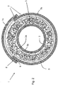
- Fig. 1 is a first embodiment of a hose liner 1 according to the invention for lining a sewer pipe to be rehabilitated.
- the tube liner 1 comprises an inner tube film 2, a resin carrier layer 3 and a further film 6 surrounding the resin carrier layer 3.
- the inner tube film 2 is known in principle from the prior art, and various designs exist. It can contain various layers, in particular permeability for UV radiation is provided in order to guide a UV radiation source through the cavity formed by the inner tube film 2 in the longitudinal direction of the tube liner 1 and thereby supply the reactive, UV-curable resin 3b dry.
- Glass fibers for example, can be used as the carrier material 3a of the resin carrier layer 3.
- Particularly suitable reactive resins 3b are reactive plastic resins known to those skilled in the art of sewer rehabilitation.
- the further film 6 is laminated with a fleece 5 on its side facing the resin carrier layer 2.
- the further film 6 can in particular contain one or more barrier layers, in particular polyamide, in order to prevent styrene originating from the resin from escaping from the resin carrier layer 3. Further barrier chemicals can also be contained in the single-layer or multilayer film 6, for example EVOH.
- the lower outer film extends in an angular range of approximately 270 °, the two longitudinal edges 8 thereof being at approximately the same horizontal height.
- An upper outer film 7c is placed on the longitudinal edges 8 of the film 7b and spans an angular range of approximately 120 °.
- the longitudinal edges 8 of the two outer foils 7b, 7c are connected to one another at three longitudinal glued seams which extend into the plane of the drawing and which in this way form connection points 9.
- connection points 9 for example double-sided adhesive tape. It is important that the longitudinal edges 8 when inflating the hose liner 1 (after introduction into the sewer to be rehabilitated in the compressed air-free state) can move against each other, ie that the connection points 9 can expand and possibly break. The connection points 9 then act as predetermined breaking points.
- connection points 9 are preferably impervious to components of the resin.
- outer foils 7b, 7c have at least one mechanically very robust layer.
- the outer foils have high abrasion resistance, great robustness, high tear and tear resistance and high puncture resistance, as they are pulled through the sewer pipe and, after inflation, lie against the sewer pipe wall and are therefore very high are exposed to mechanical loads.
- the mechanical robustness thus protects the pipe liner 1 from damage or destruction.
- Said at least one layer of the outer foils 7b, 7c can, for example, consist of an HDPE foil or a foil with a weight of more than 50%. lying polyester portion or by a reinforced fabric, for example a PVC-coated fabric (like a truck tarpaulin).
- the longitudinal edges 8 of the film 7b can also lie above the longitudinal edges 8 of the film 7c. It is also possible that one of the two longitudinal edges 8 of the film 7b lies above and the other longitudinal edge of the film 7b lies below the respective longitudinal edge 8 of the film 7c.
- the outer foils 7b, 7c also have at least one layer that is essentially impermeable to UV radiation and possibly visible light.
- the at least one layer preferably largely or almost completely suppresses transmission in the wavelength range from 300 to 500 nm, preferably from 350 to 450 nm, in particular to more than 90% and particularly preferably to more than 99%.
- Said at least one layer of the outer films 7b, 7c is preferably laminated in the form of a UV / light protection film onto the said at least one mechanically robust layer of the outer films 7b, 7c, preferably from the side facing the inside of the hose liner.
- a second tubular liner 1 according to the invention is shown in cross section, the difference being that no further film (film 6 in FIG Fig. 1 ) is provided. Rather, a fleece 5 is laminated onto each of the outer foils 7b, 7c facing the inside of the hose liner. The fleece is preferably laminated onto the said UV / light protection film.
- the one in the Fig. 2 The variant shown has the advantage that no separate film 6, which is always used in all known systems, is necessary. Rather, the outer film system 7 is present, which realizes the mechanical resistance, the UV protection and, if necessary, the protection against visible light in the vicinity of the UV radiation, as well as the connection of the resin to the nonwovens 5.
- a barrier function against, in particular, styrene can be implemented by means of a polyamide layer introduced into the outer foils 7b, 7c.
- a hose liner 1 that is relatively simply constructed, is overall very cost-effective and meets all requirements is realized.
- the outer film system 7 comprises only a single outer film 7 a, which is arranged so as to overlap on its two longitudinal edges 8.
- three adhesive seams are provided which extend perpendicular to the image plane and along the hose liner 1, expand in the circumferential direction when the hose liner 1 is expanded radially and eventually break, which form a connection point 9.
- a second outer film is dispensed with, but the single outer film 7a has to be made wider for this.
- the adhesive seams must also be designed in such a way that they actually stretch and possibly break (with two connection points 9, ie with two outer foils, the probability of a malfunction in this regard is lower).
- a fleece 5 is again laminated on the inside of the outer film 7, which is used for adhesion on the part of the resin 3b.
- the outer film 7 of the outer hose system 7 according to FIG Fig. 3 also has at least one layer impermeable to UV radiation and possibly at least near UV visible light, preferably in the form of a laminated UV / light protection film, and preferably at least one barrier layer against the passage of components of the resin, this barrier layer preferably containing polyamide .
Landscapes
- Engineering & Computer Science (AREA)
- General Engineering & Computer Science (AREA)
- Mechanical Engineering (AREA)
- Textile Engineering (AREA)
- Manufacturing & Machinery (AREA)
- Laminated Bodies (AREA)
- Lining Or Joining Of Plastics Or The Like (AREA)
Description
- Die Erfindung betrifft einen Schlauchliner nach dem Oberbegriff des Anspruchs 1. Ein solcher Schlauchliner ist aus der
EP 2 357 065 A bekannt. - Schlauchliner für die Kanalsanierung sind seit längerem bekannt. Hier ist es beispielsweise beim System Glasfaser-Schlauchliner mit UV- oder Dampfhärtung bekannt, in das zu sanierende Rohr eine dickwandige Folie aus PE mit einer hohen Dichte (HDPE - High Density Polyethylene) einzubringen, welche - zumeist in der Querschnittsform eines Halbkreises - an der Innenwand des Rohres angelegt wird. Anschließend wird ein flexibler Einlegeschlauch (auch Schlauchliner oder lediglich Liner genannt) in das zu sanierende Rohr eingezogen (Einzugsverfahren), wobei der Einlegeschlauch über die Gleitfolie gleitet. Hierdurch wird einerseits eine Beschädigung des Einlegeschlauchs durch die Rohrinnenwand bzw. Gegenstände im Rohr vermieden, andererseits ist die Reibung zwischen Einlegeschlauch und Gleitfolie sehr niedrig und erleichtert ein Einziehen des Einlegeschlauchs. Diese Funktionsweise ähnelt derjenigen eines Schuhlöffels. Ein derartiger Einlegeschlauch (Schlauchliner) weist beim System Glasfaser-Schlauchliner mit UV- oder Dampfhärtung üblicherweise einen inneren und einen äußeren Schlauch auf, zwischen denen ein Trägermaterial (beispielsweise Glasfasern) eingebracht ist, welches mit reaktivem Kunststoffharz getränkt ist. Als reaktives Kunststoffharz kommen zum Beispiel handelsübliche UP-Harze (Polyester- bzw. ungesättigte Polyesterharze), VE-Harze (Vinylesterharze) oder EP-Harze (Epoxid-Harze) zum Einsatz. Die Härtung der Harze erfolgt bei UP- oder VE-Harzen zum Beispiel mit Hilfe von Photoinitiatoren. Die Härtung kann aber auch thermisch erfolgen. Der Einlegeschlauch wird im Rohr solange aufgeblasen, bis er an der Rohrinnenwand bzw. der Gleitfolie anliegt, um anschließend das Harz - beispielsweise mittels UV-Strahlung aus einer langsam durch das Rohr gezogenen UV-Strahlungsquelle - auszuhärten. Zum Schluss kann die innere Folie des Einlegeschlauchs abgezogen und entfernt werden. Die Schicht mit dem Trägermaterial ist dann den durch das Rohr zu leitenden Substanzen exponiert.
- Ein weiterer Schlauchliner ist beispielsweise aus der
WO 2012/159702 bekannt. Hierbei wird um die Kombination aus innerer Schlauchfolie, Harz-Träger-Lage und äußerer Schlauchfolie ein Schutzschlauch aus einem reißfesten Werkstoff in Form von LKW-Planen-Material, d.h. PVC-verstärktem Gewebe, angeordnet, der einen sich in Längsrichtung des Schlauchliners erstreckenden Verbindungsabschnitt aufweist, welcher durch Einbringen von Druckluft in den Schlauchliner in Umfangsrichtung dehnbar ist. Bei einer Ausführungsform weist der Schutzschlauch aus dem reißfesten, nicht dehnbaren Material eine derartige Breite auf, dass die beiden Längsränder beim Umwickeln der äußeren Schlauchfolie nicht aneinander anstoßen oder sich überlappen. Zur Überbrückung der sich somit auftuenden Lücke (im Querschnitt gesehen) zwischen den Längsrändern des Schutzschlauches ist ein Verbindungsfolienstück aus einem dehnbaren Material vorgesehen, dass mit diesen Längsrändern des Schutzschlauches verbunden ist. Die frühzeitige Aushärtung des Harzes wird dadurch verhindert, dass die äußere, mechanisch anfällige Schlauchfolie undurchlässig für UV-Strahlung ausgebildet ist, wie dies aus dem Stand der Technik bekannt ist. - Es ist Aufgabe der vorliegenden Erfindung, einen Schlauchliner mit einer verbesserten Funktionalität bei einfachem Aufbau und günstigeren Kosten zur Verfügung zu stellen.
- Diese Aufgabe wird durch den Schlauchliner gemäß Anspruch 1 gelöst.
- Die Vorteile der Erfindung sind insbesondere darin zu sehen, dass das Außenfoliensystem des erfindungsgemäßen Schlauchliners einerseits sehr robust ist gegenüber mechanischen Einflüssen und andererseits die frühzeitige Aushärtung des Harzes (z.B. während der Lagerung) durch gleichzeitige Ausbildung als UV-Schutzfolie verhindert wird. Diese Doppelfunktion zwischen mechanischer Stärke und Schutz vor frühzeitigem Aushärten ermöglicht eine kostengünstige Ausgestaltung des erfindungsgemäßen Schlauchliners bei gleichzeitig einfachem Aufbau. Insbesondere ist der Schlauchliner aufgrund seiner mechanischen Robustheit in der Lage, in ein zu sanierendes Kanalrohr eingezogen zu werden, da der Schlauchliner auf seinem robusten, d.h. mechanisch sehr stabilem, Außenfoliensystem gleitet. Spitze Vorsprünge u.ä. im Kanalrohr können aufgrund der Reißfestigkeit und Durchstoßfestigkeit des Außenfoliensystems keine Schädigung des Schlauchliners verursachen. Da die mindestens eine Außenfolie vollständig das Harz-Träger-System umschließt, sind die oben genannten Vorteile an jeder Stelle des Schlauchliners gegeben.
- Entweder weist das Außenfoliensystem eine einzige Außenfolie auf, wobei ihre Längsränder sich überlappen und im Überlappungsbereich miteinander verbunden sind. Oder es sind mehrere, vorzugsweise zwei Außenfolien vorgesehen, welche sich an ihren Längsrändern teilweise überlappen, so dass zwei Überlappungsbereiche vorgesehen sind. Bevorzugt ist die Variante mit zwei Außenfolien.
- Im Folgenden wird häufig von den Außenfolien im Plural gesprochen. Hierbei soll aber auch die Variante mit nur einer Außenfolie abgedeckt sein.
- Die Ein- und Weiterreißfestigkeit der Außenfolie(n) ist sehr hoch, d.h. die Außenfolien sind praktisch nicht einreißbar bzw. wenn sie eingerissen sind, so liegt der Kraftaufwand für das Weiterreißen sehr hoch. Zudem weisen sie eine nur sehr geringe bis vernachlässigbare Dehnung in Maschinenrichtung (md - machine direction), d.h. in Herstellungslaufrichtung der Folie(n), auf. Mit anderen Worten ist eine hohe Kraft in Maschinenrichtung vonnöten, um überhaupt eine gewisse Dehnung zu erzeugen.
- Insgesamt weisen die Außenfolien, die einen Mono- oder Mehrschichtaufbau aufweisen können, eine hohe Reißfestigkeit, eine hohe Durchstoßfestigkeit, eine hohe Abriebfestigkeit und eine im Wesentlichen nicht vorhandene oder nur sehr schlechte Dehnbarkeit auf. Im Folgenden sind die mechanischen Eigenschaften der Außenfolie(n) wiedergegeben, wobei die Außenfolie - wie weiter unten erläutert wird - mehrere unterschiedliche Schichten aufweisen kann (einschließlich UV-Schutz und Styrol-Barriere). Erfindungsgemäß ist die Reißdehnung längs (εB) und Reißdehnung quer (εB) gemäß DIN EN ISO 527-3 bzw. DIN EN ISO 527-3 kleiner 200 %, bevorzugt kleiner 100 %, am meisten bevorzugt kleiner 50 %, und/oder ist die Weiterreißfestigkeit Trapez längs bzw. Trapez quer gemäß DIN 53363 bzw. DIN 53363 größer 100 N, bevorzugt größer 200 N, und/oder ist die Durchstoßfestigkeit gemäß ASTM E 154 größer 300 N, bevorzugt größer 500 N, besonders bevorzugt größer 800 N.
- Die mindestens eine Außenfolie ist als durch ein Gewebe, Fäden, Fasern, Gitter oder Netz verstärkte Folie oder als verstärktes Gewebe, insbesondere ein PVC-verstärktes Gewebe oder ein Kevlar (Aramidfasern)-Gewebe ausgebildet.
- Besonders bevorzugt sind die Außenfolien weiterhin entsprechend mindestens einer Ausgestaltung aus der folgenden Gruppe ausgebildet:
- enthaltend mindestens ein Olefin-Homo- oder Copolymer, vorzugsweise Polyethylen (PE), insbesondere ein High Density Polyethylen (HDPE);
- enthaltend mindestens ein Polyester;
- enthaltend mindestens ein Polyamid;
- enthaltend mindestens einen Kautschuk, ein Hartgummi, ein Gummi, ein Polystyrol, ein schlagzähes Polystyrol (HIPS), ein Styrol-Butadien-Copolymer, ein Acrylnitril-Butadien-Styrol-(Ter)Polymer (ABS), ein Polycarbonat (PC), ein Poly(meth)acrylat, PVC oder eine Mischung oder ein Blend der oben genannten Polymere oder weitere Co-, Terpolymere aus den Monomeren der oben genannten Polymere.
- Bei all diesen Ausgestaltungen ist wichtig, dass eine hohe Abriebfestigkeit, eine große Robustheit, d.h. große mechanische Stabilität, eine hohe Ein- und Weiterreißfestigkeit und eine sehr hohe Durchstoßfestigkeit (Puncture Resistance) der Außenfolien realisiert wird.
- Als in den Außenfolien einsetzbares HDPE-Material sei beispielsweise Hostalen® GD 4755 mit einer Dichte 0,953 g/cm3 von LyondellBasell Industries genannt. Die Dicke beträgt beispielsweise 300 µm.
- Ein einsetzbares PVC-verstärktes Gewebe (LKW-Plane) kann eine Dicke von 400 µm mit einem Flächengewicht von 600 g/qm aufweisen.
- Die mindestens eine Schicht, welche den UV-Schutz und ggf. den Schutz gegen sichtbares Licht der Außenfolien eines erfindungsgemäßen Schlauchliners vermittelt, wird vorzugsweise in Form einer UV-/Lichtschutzfolie realisiert, welche auf eine Außenschicht der Außenfolien aufgebracht, insbesondere aufkaschiert, wird. Diese Außenschicht ist beispielsweise eine vorwiegend Polyester enthaltende Schicht oder eine PVC-verstärkte Gewebeschicht. Die besagte UV-/Lichtschutzfolie ist vorzugsweise eine UV-Strahlung und vorteilhafterweise auch sichtbare Strahlung (zumindest einen Teil des sichtbaren Spektrums, vorteilhafterweise kurzwelliges sichtbares Licht) absorbierende und/oder reflektierende Folie. Vorzugsweise wird hierbei die UV-Strahlung im Wellenlängenbereich von 200 bis 400 nm und die Strahlen des sichtbaren Lichts im Wellenlängenbereich 400 bis 800 nm zumindest teilweise absorbiert und/oder reflektiert, vorzugsweise zu mehr als 90% und besonders bevorzugt von mehr als 99%. Insbesondere wird von der Folie eine Transmission im Wellenlängenbereich von 300 bis 500 nm, bevorzugt von 350 bis 450 nm weitgehend bis nahezu vollständig unterbunden, insbesondere zu mehr als 90% und besonders bevorzugt zu mehr als 99%. Es können hierzu organische und/oder anorganische Farbpigmente, Farbstoffe sowie ggf. UV-Absorber bzw. Verbindungen zum Einsatz kommen, die dem Fachmann bekannt sind (s. z.B. die
DE 10 2009 041 841 A1 ). Die UV-/Lichtschutzfolie kann daher vollkommen blickdicht sein, oder sie ist transparent oder zumindest kontakttransparent. - Eine solche UV- und ggf. Licht-Schutzfolie ist bevorzugt an der der Harz-Träger-Lage zugewandten Außenseite der Außenfolie aufkaschiert.
- In einer solchen aufkaschierten UV- und ggf. Licht-Schutzfolie können - gemäß einer ganz bevorzugten Ausführungsform - zudem chemische Verbindungen enthalten sein, die eine Barrierefunktion gegenüber insbesondere Monomeren, Harzen, Ölen, Fetten, Gasen, etc. ausüben. Insbesondere kann hierbei Polyamid in der UV-/Lichtschutzfolie Einsatz finden (s. hierzu auch weiter unten).
- Gemäß einer vorteilhaften Ausführungsform kann eine Folie mit einer solchen Barriereschicht auch alternativ oder zusätzlich zu der UV- und ggf. Licht-Schutzfolie auf die Außenfolien aufkaschiert sein.
- Im Folgenden werden zwei Beispiele für eine UV-/Lichtschutzfolie gegeben, wobei die verwendeten Chemikalien im Fachhandel erhältlich sind:
Beispiel 1: silbrige Folie mit UV-Absorber; Farbbatch: Grafe 13-08485 Schicht-Nummer Zusammensetzung Anteil in Schicht in Gew-% Dicke in µm 1 • Luvofilm 9679 • 0,5 35 • Lupolen 2420 F • 79,5 • Farbbatch silber • 20 2 • Haftvermittler Mitsui • 96 12 Admer NF 498 E • • UV-Absorber Constab UVA 01490 LD • 4 3 • Durethan C 38 F • 100 26 4 • Haftvermittler Mitsui • 96 12 Wie 2 Admer NF 498 E • • UV-Absorber Constab UVA 01490 LD • 4 5 • Luvofilm 9679 • 0,5 35 Wie 1 • Lupolen 2420 F • 79,5 • Farbbatch silber • 20 Gesamtdicke: 130 µ Beispiel 2: silbrige Folie mit UV-Absorber; Farbbatch: Grafe 13-08486 Schicht-Nummer Zusammensetzung Anteil in Schicht in Gew-% Dicke in µm 1 • Luvofilm 9679 • 0,5 35 • Lupolen 2420 F • 79,5 • Farbbatch silber • 20 2 • Haftvermittler Mitsui • 96 12 Admer NF 498 E • • UV-Absorber Constab UVA 01490 LD • 4 3 • Durethan C 38 F • 100 26 4 • Haftvermittler Mitsui • 96 12 Wie 2 Admer NF 498 E • • UV-Absorber Constab UVA 01490 LD • 4 5 • Luvofilm 9679 • 0,5 35 Wie 1 • Lupolen 2420 F • 79,5 • Farbbatch silber • 20 Gesamtdicke 130 µ - Die Außenfolien weisen bevorzugt eine Dicke im Bereich 50 bis 10.000 µm, bevorzugt 100 bis 5.000 µm, besonders bevorzugt 200 µm bis 1000 µm auf.
- Die Verbindungsstellen zwischen den sich überlappenden Längsrändern nur einer verwendeten Außenfolie bzw. zwischen den Längsrändern mehrerer Außenfolien sind besonders bevorzugt als Sollbruchstellen ausgebildet. Bei radialer Dehnung des Schlauchliners beim Aufblasen nach Einbringung in das zu sanierende Kanalrohr brechen die Sollbruchstellen und die Längsränder der Außenfolie(n) verschieben sich in Umfangsrichtung zueinander. Da der Aushärtevorgang kurz danach beginnt, kann durch sich ggf. herbei auftuenden Lücken Harz in nennenswerter Menge nicht austreten.
- Die sich überlappenden Längsränder der Außenfolien sind vorzugsweise mittels eines ggf. doppelseitigen Klebebands, einer thermischen Schweißnaht, eines Hotmelt-Klebers oder eines sonstigen Klebers in Form einer durchgehenden Klebenaht oder unterbrochenem Kleberauftrag miteinander verbunden. Eine Verklebung kann beispielsweise mittels eines handelsüblichen 2K PUR Klebers erfolgen. Weitere Beispiele finden sich in der oben genannten
WO 2012/159702 . Es kann auch ein Standard-Gewebeband, ein Panzerband, ein Panzertape, oder ein Packband (beispielsweise 50m x 38mm silber) verwendet werden. - Es ist bevorzugt, wenn die Verbindungsstellen in den Überlappungsbereichen dicht gegenüber Komponenten des Harzes sind, so dass an keiner Stelle des Außenfoliensystems Bestandteile des Harzes austreten können.
- Besonders bevorzugt ist auf der zur Harz-Träger-Lage gerichteten Seite zumindest einer Außenfolie, vorzugsweise allen Außenfolien, ein für Harz oder Flüssigkeiten saugfähiges Material, wie z.B. ein Vlies, aufkaschiert. Dieses Material liegt dann direkt der Harz-Träger-Lage gegenüber und ermöglicht eine bessere Anbindung des Harzes. Statt einer Kaschierung kann das Material, z.B. ein Vlies, beispielsweise auch aufgetackert werden. Der Fachmann kennt die Methoden zur Verbindung von Folien mit Materialien, die Harze und Flüssigkeiten aufsaugen können.
- Gemäß einer Alternative ist zwischen den Außenfolien und der Harz-Träger-Lage mindestens eine weitere separate (d.h. nicht aufkaschierte) Folie angeordnet. Diese kann beispielsweise eine Wickelfolie sein, welche um das Harz-Träger-System gewickelt ist. Auch ist es möglich, dass diese mindestens eine Folie eine Verkleidungsfolie ist. Auf der weiteren Folie - zur Seite des Harz-Träger-Systems hin - ist gemäß einer vorteilhaften Ausführungsform ein Vlies oder ein Nonwoven aufgebracht. Die Dicke dieser Folie beträgt vorzugweise 10 bis 1000 µm, während das Vlies bzw. das Nonwoven ein Flächengewicht von vorzugsweise 5 g/qm bis 500 g/qm aufweist.
- Die mindestens eine weitere Folie kann auch als eine Barrierefolie mit einer sehr guten Haftung zum Harz ausgebildet sein. Ein Vlies (bzw. allgemein ein für Flüssigkeiten und Harze saugfähiges Material) ist dann nicht notwendig.
- Die mindestens eine weitere Folie (Schutzfolie, Wickelfolie) kann beispielsweise eine 50 µ PE-PA-PE-Folie mit dem Aufbau: PE 10 µm, Haftvermittler 5 µm, PA 10 µm, Haftvermittler 5 µm, PE 10 µm, kaschiert gegen ein 50 g/qm Vlies sein. Das ATG kann 15 g/qm betragen.
- Die mindestens eine weitere Folie kann mittels Umwickeln der Harz-Träger-Lage aufgebracht werden. Alternativ kann die mindestens eine weitere Folie in Form einer Flachfolie vorliegen, welche um die Harz-Träger gehüllt und anschließend verschweißt wird. Auch eine Schlauchfolie oder ein schlauchförmiger Verbund aus Folie/Nonwoven ist als die mindestens eine weitere Folie denkbar. Der Zweck dieser mindestens einen weiteren Folie ist der Schutz des reaktiven Harzes, damit dieses nicht in die Umwelt austreten kann.
- Vorzugsweise ist in mindestens einer Folie, die um das Harz-Träger-System angeordnet ist, ein Polyamid als Styrolbarriere enthalten. Polyamid kann gemäß einem bevorzugten Ausführungsbeispiel insbesondere in einer Schicht der Außenfolien enthalten sein. Der Polyamid-Anteil in dieser Schicht beträgt hierbei beispielsweise mehr als 50 Gew.-%. Gemäß einer Alternative ist in einer Schicht der oben genannten mindestens einen weiteren Folie Polyamid in genügender Menge enthalten, damit diese Schicht als Styrolbarriere dienen kann.
- Diesbezüglich ist es bevorzugt, wenn mindestens eine Schicht der Außenfolien als Barriereschicht gegen Komponenten des reaktiven Harzes ausgebildet ist.
- Eine besonders bevorzugte Ausführungsform des erfindungsgemäßen Schlauchliners weist Außenfolien auf, welche die besagte mechanische Robustheit bzw. Stabilität aufweisen, gegen UV-Strahlung und ggf. sichtbares Licht weitgehend undurchlässig sind und eine Barriere gegen Styrol aufweisen. Zusätzlich kann noch ein Vlies oder ein Nonwoven zur Seite der Harz-Träger-Lage angeordnet sein.
- Gemäß einer vorteilhaften Ausführungsform überstreicht diejenige Außenfolie, die an der Kanalrohrsohle zur Anlage vorgesehen ist, in Umfangsrichtung einen Winkelbereich von mehr als 180°, beispielsweise von mehr als 240°. Bei einem Winkelbereich von 180° befinden sich die beiden Längsränder dieser Außenfolie vorzugsweise auf horizontal gleicher Höhe. Beim Einziehen des erfindungsgemäßen Schlauchliners in ein zu sanierendes Kanalrohr gleitet dann der Schlauchliner auf dieser unteren Außenfolie über die Kanalrohrsohle.
- Vorzugsweise ist eine im Querschnitt gesehen obere Außenfolie vorgesehen, der in Umfangsrichtung einen Winkelbereich von weniger als 180° überstreicht und von oben auf eine untere Außenfolie aufgesetzt und randseitig mit diesem unter Bildung einer Überlappung verbunden ist. Diese obere Außenfolie ist dann eine Art Deckel für einen oder mehrere untere Außenfolien. Die Verbindungsstellen sind zwischen der oberen und einer unteren Außenfolie liegen dann oberhalb der Belastungsstellen beim Einziehen des Schlauchliners in ein Kanalrohr.
- Im Folgenden wird kurz auf die bevorzugte Beschaffenheit der Schlauchinnenfolie des erfindungsgemäßen Schlauchliners eingegangen. Diese muss im Gegensatz zum Außenfoliensystem eine sehr gute Durchlässigkeit gegenüber UV-Strahlung und kürzerwelliger Strahlung sichtbaren Lichts aufweisen. Damit wird der Aushärtungsvorgang ermöglicht, der beim im Rohr aufgeblasenen Schlauchliner durch eine UV-Strahlungsquelle vorgenommen wird, die an der Innenseite des Schlauchliners, also innerhalb der Schlauchinnenfolie, hindurchgezogen wird.
- Außerdem darf die Schlauchinnenfolie bei Druckbeaufschlagung nicht platzen und muss eine gute Dehnbarkeit aufweisen, um den Schlauchliner im Kanal aufstellen zu können.
- Die Schlauchinnenfolie kann beispielsweise gemäß der
EP 2 740 592 A oder derEP 2 740 587 A ausgebildet sein. - Ein beispielhafter Aufbau einer Schlauchinnenfolie kann wie folgt aussehen:
Schicht-Nummer Zusammensetzung Anteil in Schicht in % Dicke in µm (1) • Durethan C38 F • 88 40 • Durethan B40 FAM • 12 (2) • Haftvermittler: Admer NF 498 E • 100 10 (3) • Lupolen 2420 F • 70 65 • Exceed 1327 CA • 30 (4) • Haftvermittler: Admer NF 498 E • 100 10 (5) • Lupolen 2420 F • 70 75 • Exceed 1327 CA • 30 Gesamtdicke: 200 µm - Als Harz-Träger-Systeme kommen beispielsweise die oben genannten Systeme in Frage. Das Trägersystem kann beispielweise in Form von Glasfasern ausgebildet sein.
- Aus dem oben Gesagten wird klar, dass die Außenfolien aufgebrachte Folien aufweisen können, wobei beispielsweise eine Thermokaschierung, eine Extrusionskaschierung, eine Kleberkaschierung, eine Kalandrierung oder sonstige dem Fachmann geläufige Arten zur Verbindung von Folien miteinander oder von Folien mit Vlieses bzw. Nonwoven bzw. ein für Flüssigkeiten und Harze saugfähiges Material zum Einsatz kommen kann. Eine solche Verbindung kann zwischen einer UV-/Lichtschutzfolie mit einer mechanisch robusten, d.h. mechanisch sehr stabile, Folie bzw. einem solchen Gewebe realisiert werden. Auch kann die UV-/Lichtschutzfolie und ein Vlies bzw. Nonwoven derart verbunden werden, wobei diese Kombination dann zusammen mit der auf ihr aufgebrachten mechanisch robusten Folie Bestandteil des erfindungsgemäßen Außenfoliensystems ist.
- In den Figuren sind schematisch zwei verschiedene Ausführungsbeispiele der Erfindung dargestellt. Es zeigen:
- Fig. 1
- eine erste Ausführungsform eines erfindungsgemäßen Schlauchliners mit zwei Außenfolien und separater weiterer Folie mit aufkaschiertem Vlies, im Querschnitt;
- Fig. 2
- eine zweite Ausführungsform eines erfindungsgemäßen Schlauchliners mit zwei Außenfolien und auf beiden Außenfolien aufkaschierten Vliesen, im Querschnitt, und
- Fig. 3
- eine zweite Ausführungsform eines erfindungsgemäßen Schlauchliners mit nur einer Außenfolie und aufkaschiertem Vlies, im Querschnitt.
- In der
Fig. 1 ist ein erstes Ausführungsbeispiel eines erfindungsgemäßen Schlauchliners 1 zur Auskleidung eines zu sanierenden Kanalrohrs dargestellt. Der Schlauchliner 1 umfasst eine Schlauchinnenfolie 2, eine Harz-Träger-Lage 3 und eine die Harz-Träger-Lage 3 umgebende weitere Folie 6. - Die Schlauchinnenfolie 2 ist prinzipiell aus dem Stand der Technik bekannt, wobei diverse Ausführungen existieren. Sie kann verschiedene Schichten enthalten, wobei insbesondere eine Durchlässigkeit für UV-Strahlung vorhanden ist, um eine UV-Strahlungsquelle durch den von der Schlauchinnenfolie 2 gebildeten Hohlraum in Längsrichtung des Schlauchliners 1 zu führen und hierdurch das reaktive, durch UV-Strahlung aushärtbare Harz 3b zu trocknen.
- Als Trägermaterial 3a der Harz-Träger-Lage 3 sind beispielsweise Glasfasern verwendbar. Als reaktive Harze 3b kommen insbesondere reaktive Kunststoffharze in Frage, die der Fachmann aus dem Kanalsanierungsbereich kennt.
- Die weitere Folie 6 ist auf ihrer zur Harz-Träger-Lage 2 gerichteten Seite mit einem Vlies 5 kaschiert. Die weitere Folie 6 kann insbesondere eine oder mehrere Barriereschichten, insbesondere Polyamid enthalten, aufweisen, um aus dem Harz stammendes Styrol am Entweichen aus der Harz-Träger-Lage 3 zu hindern. Auch können weitere Barriere-Chemikalien in der ein- oder mehrschichtigen Folie 6 enthalten sein, beispielsweise EVOH.
- Um die weitere Folie 6 herum ist ein Außenfoliensystem 7 angeordnet, das vorliegend zwei Außenfolien 7b, 7c umfasst. Die untere Außenfolie erstreckt sich in einem Winkelbereich von ca. 270°, wobei deren beiden Längsränder 8 auf ungefähr gleicher horizontaler Höhe liegen. Auf die Längsränder 8 der Folie 7b ist eine obere Außenfolie 7c aufgelegt, welche einen Winkelbereich von ca. 120° überspannt. Die Längsränder 8 der beiden Außenfolien 7b, 7c sind an sich in die Bildebene hinein erstreckenden drei Längsklebenähten miteinander verbunden, die auf diese Weise Verbindungsstellen 9 bilden.
- Zum Herstellen der Verbindungsstellen 9 können die unterschiedlichsten Klebetechniken angewendet werden, beispielsweise doppelseitiges Klebeband. Wichtig ist, dass die Längsränder 8 beim Aufblasen des Schlauchliners 1 (nach Einbringen in den zu sanierenden Kanal im druckluftlosen Zustand) sich gegeneinander verschieben können, d.h. dass die Verbindungsstellen 9 sich dehnen und ggf. brechen können. Die Verbindungsstellen 9 wirken dann als Sollbruchstellen.
- Die den Überlappungsbereiche mit den Verbindungsstellen 9 sind bevorzugt dicht gegenüber Komponenten des Harzes.
- Dieses Vorsehen der Dehnung in Umfangsrichtung (bei Aufbringung von radialem Druck von innen her) ist wichtig, da die Außenfolien 7b, 7c mindestens eine mechanisch sehr robuste Schicht aufweisen. Hierunter wird verstanden, dass die Außenfolien eine hohe Abriebfestigkeit, eine große Robustheit, eine hohe Ein- und Weiterreißfestigkeit und eine hohe Durchstoßfestigkeit (Puncture Resistance) aufweisen, da sie durch das Kanalrohr gezogen werden und nach dem Aufblasen an der Kanalrohrwand anliegen und somit sehr hohen mechanischen Belastungen ausgesetzt sind. Die mechanische Robustheit schützt den Schlauchliner 1 somit vor einer Beschädigung bzw. Zerstörung.
- Die besagte mindestens eine Schicht der Außenfolien 7b, 7c kann beispielsweise durch eine HDPE-Folie, durch eine Folie mit einem über 50 Gew-%. liegenden Polyester-Anteil oder durch ein verstärktes Gewebe, beispielsweise eine PVC-beschichtetes Gewebe (wie bei einer LKW-Plane) realisiert werden.
- Bei der Überlappung können die Längsränder 8 der Folie 7b auch oberhalb der Längsränder 8 der Folie 7c liegen. Auch ist es möglich, dass einer der beiden Längsränder 8 der Folie 7b oberhalb und der andere Längsrand der Folie 7b unterhalb des jeweiligen Längsrandes 8 der Folie 7c liegt.
- Die Außenfolien 7b, 7c weisen zudem mindestens eine für UV-Strahlung und ggf. sichtbares Licht im Wesentlichen undurchlässige Schicht auf. Hierzu beinhaltet diese Schicht beispielsweise organische und/oder anorganische Farbpigmente, Farbstoffe sowie ggf. UV-Absorber bzw. Verbindungen, die dem Fachmann bekannt sind, z.B. aus der
DE 10 2009 041 841 A1 . Insbesondere wird durch die mindestens eine Schicht bevorzugt eine Transmission im Wellenlängenbereich von 300 bis 500 nm, bevorzugt von 350 bis 450 nm weitgehend bis nahezu vollständig unterbunden, insbesondere zu mehr als 90% und besonders bevorzugt zu mehr als 99%. - Die besagte mindestens eine Schicht der Außenfolien 7b, 7c wird vorzugsweise in Form einer UV-/Lichtschutzfolie auf die besagte mindestens eine mechanisch robuste Schicht der Außenfolien 7b, 7c aufkaschiert, vorzugsweise von der zum Schlauchliner-Inneren gewandten Seite.
- In der
Fig. 2 , in der gleiche Bezugszeichen für gleiche oder vergleichbare Merkmale verwendet wurden, ist ein zweiter erfindungsgemäßer Schlauchliner 1 im Querschnitt dargestellt, wobei der Unterschied darin besteht, dass keine weitere Folie (Folie 6 in derFig. 1 ) vorgesehen ist. Vielmehr ist auf den zum Schlauchliner-Inneren gewandten Außenfolien 7b, 7c jeweils ein Vlies 5 aufkaschiert. Das Vlies wird hierbei vorzugsweise auf die besagte UV-/Lichtschutzfolie aufkaschiert. - Die in der
Fig. 2 gezeigte Variante hat den Vorteil, dass keine separate Folie 6, die bei allen bekannten Systemen stets verwendet wird, notwendig ist. Es ist vielmehr das Außenfoliensystem 7 vorhanden, welches die mechanische Widerstandfähigkeit, den UV-Schutz und ggf. den Schutz gegen der UV-Strahlung nahem sichtbarem Licht sowie die Anbindung des Harzes an die Vliese 5 realisiert. Zudem kann eine Barrierefunktion gegenüber insbesondere Styrol mittels einer in den Außenfolien 7b, 7c eingebrachten Polyamid-Schicht realisiert werden. Insgesamt wird ein relativ einfach aufgebauter, insgesamt sehr kostengünstiger und allen Anforderungen gerecht werdender Schlauchliner 1 realisiert. - In der
Fig. 3 ist schließlich ein drittes Ausführungsbeispiel eines erfindungsgemäßen Schlauchliners 1 dargestellt. Hierbei umfasst das Außenfoliensystem 7 lediglich eine einzige Außenfolie 7a, welche an ihren beiden Längsrändern 8 überlappend angeordnet ist. Auch hier sind drei senkrecht zur Bildebene und sich längs des Schlauchliners 1 erstreckende, bei radialer Dehnung des Schlauchliners 1 sich in Umfangsrichtung dehnende und schließlich möglicherweise brechende Klebenähte vorgesehen, welche eine Verbindungsstelle 9 bilden. Bei dieser Variante wird zwar auf eine zweite Außenfolie verzichtet, die einzige Außenfolie 7a muss allerdings dafür breitere hergestellt werden. Auch müssen die Klebenähte derart ausgeführt sein, dass sie sich tatsächlich dehnen und ggf. brechen (bei zwei Verbindungsstellen 9, d.h. bei zwei Außenfolien, ist die Wahrscheinlichkeit einer diesbezüglichen Fehlfunktion geringer). - Wie der
Fig. 3 weiter zu entnehmen ist, ist auf der Innenseite der Außenfolie 7 wiederum ein Vlies 5 kaschiert, das zur Anhaftung seitens des Harzes 3b dient. - Die Außenfolie 7 des Außenschlauchsystems 7 gemäß der
Fig. 3 weist zudem mindestens eine für UV-Strahlung und ggf. zumindest UV-nahes sichtbares Licht undurchlässige Schicht, vorzugsweise in Form einer aufkaschierten UV-/Lichtschutzfolie, sowie bevorzugt mindestens eine Barriereschicht gegen den Durchtritt von Komponenten des Harzes auf, wobei diese Barriereschicht vorzugsweise Polyamid enthält.
Claims (13)
- Schlauchliner (1) für die Kanalsanierung, mit mindestens:- einer Schlauchinnenfolie (2);- mit einer die Schlauchinnenfolie (2) umgebenden Harz-Träger-Lage (3), wobei das Harz (3b) mittels UV-Strahlung aushärtbar ist;- mit einem die Harz-Träger-Lage (3) umgebenden, mechanisch schützenden Außenfoliensystem (7) mit mindestens einer sich in Längsrichtung des Schlauchliners (1) erstreckenden Außenfolie (7a; 7a, 7b), wobei die Längsränder (8) der Außenfolie (7a) oder der Außenfolien (7b, 7c) in Umfangsrichtung des Schlauchliners (1) überlappend miteinander verbunden sind, wobei die daraus resultierende mindestens eine Verbindungsstelle (9) bei Dehnung in Radialrichtung beim Einbringen des Schlauchliners (1) in einen zu sanierenden Kanal sich dehnt und ggf. bricht, und wobei die mindestens eine Außenfolie (7a; 7b, 7c) mindestens eine für UV-Strahlung und ggf. sichtbares Licht im Wesentlichen undurchlässige Schicht aufweist,dadurch gekennzeichnet, dass
die mindestens eine Außenfolie (7a; 7b, 7c) jeweils mindestens eine Schicht aus einem mechanisch sehr stabilen und im Wesentlichen nicht oder nur sehr schlecht dehnbaren Werkstoff aufweist, wobei die mindestens eine Außenfolie (7a; 7b, 7c) ausgebildet ist als durch ein Gewebe, Fäden, Fasern, Gitter oder Netz verstärkte Folie oder als verstärktes Gewebe, insbesondere ein PVC-verstärktes Gewebe oder ein Kevlar (Aramidfasern)-Gewebe, und wobei die besagte mechanische Stabilität und schlechte Dehnbarkeit der mindestens einen Außenfolie (7a; 7b, 7c) durch eine oder mehrere der folgenden mechanischen Eigenschaften definiert ist:- die Reißdehnung längs (εB) und Reißdehnung quer (εB) gemäß DIN EN ISO 527-3 bzw. DIN EN ISO 527-3 ist kleiner 200 %, bevorzugt kleiner 100 %, am meisten bevorzugt kleiner 50 %;- die Weiterreißfestigkeit Trapez längs bzw. Trapez quer gemäß DIN 53363 bzw. DIN 53363 ist größer 100 N, bevorzugt größer 200 N; und/oder- die Durchstoßfestigkeit gemäß ASTM E 154 ist größer 300 N, bevorzugt größer 500 N, besonders bevorzugt größer 800 N. - Schlauchliner nach Anspruch 1, dadurch gekennzeichnet, dass die mindestens eine Außenfolie (7a; 7b, 7c) weiterhin entsprechend mindestens einer Ausgestaltung aus der folgenden Gruppe ausgebildet ist:- enthaltend mindestens ein Olefin-Homo- oder Copolymer, vorzugsweise Polyethylen (PE), insbesondere ein High Density Polyethylen (HDPE),- enthaltend mindestens ein Polyester,- enthaltend mindestens ein Polyamid,- enthaltend mindestens einen Kautschuk, ein Hartgummi, ein Gummi, ein Polystyrol, ein schlagzähes Polystyrol (HIPS), ein StyrolButadien-Copolymer, ein Acrylnitril-Butadien-Styrol-(Ter)Polymer (ABS), ein Polycarbonat (PC), ein Poly(meth)acrylat, PVC oder eine Mischung oder ein Blend der oben genannten Polymere oder weitere Co-, Terpolymere aus den Monomeren der oben genannten Polymere.
- Schlauchliner nach mindestens einem der vorhergehenden Ansprüche, dadurch gekennzeichnet, dass UV- und sichtbares Licht-Strahlung im Wellenlängenbereich von 300 bis 500 nm, bevorzugt von 350 bis 450 nm, zu mehr als 90% und besonders bevorzugt zu mehr als 99% unterbunden wird, insbesondere durch Zusatz von organischen und/oder anorganischen Farbpigmente und Farbstoffen sowie ggf. UV-Absorbern in mindestens eine Schicht der mindestens einen Außenfolie (7a; 7b, 7c).
- Schlauchliner nach mindestens einem der vorhergehenden Ansprüche, dadurch gekennzeichnet, dass die mindestens eine für UV-Strahlung und ggf. sichtbares Licht im Wesentlichen undurchlässige Schicht in Form einer UV-/Lichtschutzfolie auf die besagte mechanisch stabile Schicht aufkaschiert ist, ggf. mit einer oder mehreren Zwischenschichten.
- Schlauchliner nach mindestens einem der vorhergehenden Ansprüche, dadurch gekennzeichnet, dass die Dicke der mindestens einen Außenfolie (7a; 7b, 7c) im Bereich 50 bis 10.000 µm, bevorzugt 100 bis 5.000 µm, besonders bevorzugt 200 µm bis 1000 µm beträgt.
- Schlauchliner nach mindestens einem der vorhergehenden Ansprüche, dadurch gekennzeichnet, dass die mindestens eine Verbindungsstelle (9) zwischen den Längsrändern der Außenfolie (7a) bzw. Außenfolien (7b, 7c) eine Sollbruchstelle darstellt, die bei radialer Dehnung des Schlauchliners (1) zu platzen oder aufzubrechen vermag.
- Schlauchliner nach mindestens einem der vorhergehenden Ansprüche, dadurch gekennzeichnet, dass die sich überlappenden Längsränder (8) mittels eines ggf. doppelseitigen Klebebands, einer thermischen Schweißnaht, eines Hotmelt-Klebers oder eines sonstigen Klebers in Form einer durchgehenden Klebenaht oder unterbrochenem Kleberauftrag miteinander verbunden sind.
- Schlauchliner nach mindestens einem der vorhergehenden Ansprüche, dadurch gekennzeichnet, dass auf der zur Harz-Träger-Lage (3) gerichteten Innenseite zumindest einer Außenfolie (7a; 7b, 7c), vorzugsweise auf allen Außenfolien (7a; 7b, 7c), ein Vlies (5) oder ein anderes für Flüssigkeiten und Harze saugfähiges Material aufgebracht ist zum Zwecke der besseren Anhaftung an das Harz der Harz-Träger-Lage (3).
- Schlauchliner nach mindestens einem der vorhergehenden Ansprüche, dadurch gekennzeichnet, dass zwischen der Harz-Träger-Lage (3) und dem Außenfoliensystem (7) mindestens eine Folie vorgesehen ist, insbesondere eine Wickelfolie (6) oder eine Verkleidungsfolie (6), die ggf. verbunden sind mit einem Vlies (5) oder einem anderen für Flüssigkeiten und Harze saugfähigem Material.
- Schlauchliner nach mindestens einem der vorhergehenden Ansprüche, dadurch gekennzeichnet, dass zumindest in einer Schicht einer die Harz-Träger-Lage (3) umgebenden Folie (7a, 7b; 6) ein Polyamid als Styrolbarriere enthalten ist.
- Schlauchliner nach mindestens einem der vorhergehenden Ansprüche, dadurch gekennzeichnet, dass mindestens eine Schicht der mindestens einen Außenfolie (7a; 7b, 7c) eine Barrierefunktion gegen Komponenten des reaktiven Harzes besitzen.
- Schlauchliner nach mindestens einem der vorhergehenden Ansprüche, dadurch gekennzeichnet, dass diejenige Außenfolie (7a; 7b), die an der Kanalrohrsohle zur Anlage vorgesehen ist, in Umfangsrichtung einen Winkelbereich von mehr als 180° überstreicht, wie beispielsweise von mehr als 240°.
- Schlauchliner nach mindestens einem der vorhergehenden Ansprüche, dadurch gekennzeichnet, dass eine im Querschnitt gesehen obere Außenfolie (7c) vorgesehen ist, der in Umfangsrichtung einen Winkelbereich von weniger als 180° überstreicht und von oben auf eine untere Außenfolie (7b) aufgesetzt und randseitig mit diesem unter Bildung einer Überlappung verbunden ist.
Priority Applications (1)
| Application Number | Priority Date | Filing Date | Title |
|---|---|---|---|
| PL15188733T PL3006805T3 (pl) | 2014-10-08 | 2015-10-07 | Wkładka rurowa do renowacji kanału |
Applications Claiming Priority (1)
| Application Number | Priority Date | Filing Date | Title |
|---|---|---|---|
| DE102014114627.1A DE102014114627A1 (de) | 2014-10-08 | 2014-10-08 | Schlauchliner für die Kanalsanierung |
Publications (2)
| Publication Number | Publication Date |
|---|---|
| EP3006805A1 EP3006805A1 (de) | 2016-04-13 |
| EP3006805B1 true EP3006805B1 (de) | 2021-09-22 |
Family
ID=54292624
Family Applications (1)
| Application Number | Title | Priority Date | Filing Date |
|---|---|---|---|
| EP15188733.8A Active EP3006805B1 (de) | 2014-10-08 | 2015-10-07 | Schlauchliner für die kanalsanierung |
Country Status (6)
| Country | Link |
|---|---|
| US (1) | US9897242B2 (de) |
| EP (1) | EP3006805B1 (de) |
| DE (1) | DE102014114627A1 (de) |
| DK (1) | DK3006805T3 (de) |
| ES (1) | ES2900836T3 (de) |
| PL (1) | PL3006805T3 (de) |
Cited By (1)
| Publication number | Priority date | Publication date | Assignee | Title |
|---|---|---|---|---|
| EP4530519A1 (de) * | 2023-09-27 | 2025-04-02 | Rainer Schuster | Relining-schlauch, verfahren zum auskleiden eines schlitzrinnenkanals mit einem relining-schlauch und vorrichtung zur herstellung eines relining-schlauches |
Families Citing this family (12)
| Publication number | Priority date | Publication date | Assignee | Title |
|---|---|---|---|---|
| DE102015013856A1 (de) * | 2015-10-06 | 2017-04-06 | Brandenburger Patentverwertung GbR (vertretungsberechtigter Gesellschafter: Tim Brandenburger, 76829 Landau) | Auskleidungsschlauch für die Kanalsanierung sowie Verfahren zur Herstellung eines solchen |
| AU2017274084B2 (en) * | 2016-06-01 | 2024-03-07 | Versapipe Pte. Ltd. | Construction of tubular assemblies |
| EP3321554B1 (de) * | 2016-10-18 | 2020-04-01 | Bolonia Servicios e Ingenieros, S.L. | Vorrichtung zur härtung der innenauskleidung einer rohrleitung |
| DE102016120225B4 (de) * | 2016-10-24 | 2024-12-05 | Buergofol GmbH | Abdichtsystem insbesondere für Einlegeschläuche, Einlegeschlauch und Verfahren zum Herstellen eines Einlegeschlauchs sowie Verfahren zum Auskleiden eines Rohrs mit einem Einlegeschlauch und Verwendung eines Dichtungsbands für die Herstellung eines Einlegeschlauchs |
| DE102018106561A1 (de) | 2018-03-20 | 2019-09-26 | Buergofol GmbH | Schlauchliner für die Sanierung eines Kanals |
| DE102020117472B4 (de) | 2020-07-02 | 2022-08-04 | Impreg Gmbh | Einlegeschlauch zum Auskleiden von Rohrleitungen oder Kanälen |
| US11577200B1 (en) * | 2021-04-16 | 2023-02-14 | Ina Acquisition Corp. | VOC mitigation in cured in place pipe installation |
| US20230023662A1 (en) * | 2021-07-26 | 2023-01-26 | Motivo Group, Inc. | Chemical Sewer Pipe Liner System and Method |
| CN114407463B (zh) * | 2021-12-22 | 2023-04-11 | 北京工商大学 | 一种非开挖修复用原位固化法管道修复用的抗紫外多层保护膜及其制备方法 |
| DE102022119919A1 (de) | 2022-08-08 | 2024-02-08 | Kurt Stark | Kontakttransparentes UV- und Licht-Schutzsystem für Schlauchliner zur grabenlosen Kanalsanierung mit besonderer mechanischer Stabilität |
| DE102022119914A1 (de) | 2022-08-08 | 2024-02-08 | Kurt Stark | Kontakttransparentes UV- und Licht-Schutzsystem für Schlauchliner zur grabenlosen Kanalsanierung |
| WO2024178204A1 (en) * | 2023-02-24 | 2024-08-29 | Illinois Tool Works Inc. | Outer film for cured-in-place pipe liner |
Family Cites Families (18)
| Publication number | Priority date | Publication date | Assignee | Title |
|---|---|---|---|---|
| DE29700236U1 (de) * | 1997-01-10 | 1998-05-14 | Scheiff GmbH, 53881 Euskirchen | Verbundschlauch für die Kanalsanierung |
| AU8991998A (en) | 1997-09-04 | 1999-03-22 | Texon Uk Limited | Renovative pipeliner |
| GB9908602D0 (en) | 1999-04-15 | 1999-06-09 | Northumbria Lyonnaise Technolo | Rehabilitation of water supply pipes |
| DE19924251A1 (de) * | 1999-05-27 | 2000-11-30 | Joachim Brandenburger | Auskleidungsschlauch mit auf Folienschlauch aufkaschierter Vliesschicht |
| US6732763B2 (en) | 2002-05-24 | 2004-05-11 | Lantor, Inc. | Stretch-resistant pipe liner |
| US20050217747A1 (en) | 2004-03-30 | 2005-10-06 | Buriak Paul J | Thermoplastic pipe and liners |
| US20060112998A1 (en) | 2004-12-01 | 2006-06-01 | Tekni-Plex, Inc. | Multi-layered hose |
| US8580364B2 (en) * | 2008-09-19 | 2013-11-12 | Rene Quitter | Cured-in-place liner material and methods and systems for manufacture |
| DE102009041841A1 (de) * | 2008-12-17 | 2010-07-08 | Huhtamaki Forchheim Zweigniederlassung Der Huhtamaki Deutschland Gmbh & Co. Kg | UV- und Licht-Schutzfolie |
| DE102009006470B4 (de) | 2008-12-23 | 2012-04-12 | Alkor Folien Gmbh | Peelbare Folie für faserige Substrate, Verbund aus der Folie und einem Substrat und Verwendung desselben |
| EP2357065A1 (de) * | 2010-02-12 | 2011-08-17 | Per Aarsleff A/S | Imprägnieranlage zum Imprägnieren einer Einlage mit einer Sperrschicht |
| DE102010023764B4 (de) | 2010-06-15 | 2019-10-17 | Infiana Germany Gmbh & Co. Kg | Einlegeschlauch umfassend eine UV-Strahlung durchlässige Mehrschichtfolie sowie Rohrsanierungssystem umfassend den Einlegeschlauch |
| DE102011103001B4 (de) | 2011-05-24 | 2023-03-16 | Brandenburger Liner Gmbh & Co. Kg | Auskleidungsschlauch zur Sanierung von defekten Abwasserkanälen |
| DE102011105995B4 (de) | 2011-06-30 | 2016-09-01 | Sml Verwaltungs Gmbh | Photochemisch härtbare Auskleidungsschläuche zur Sanierung fluidführender Systeme und deren Verwendung |
| DE102011111172A1 (de) | 2011-08-25 | 2014-03-13 | Huhtamaki Films Germany Gmbh & Co. Kg | Einlegeschlauch zur Kanalisierung |
| US20140166147A1 (en) | 2012-12-10 | 2014-06-19 | Buergofol GmbH | Multilayer Film |
| ES2912607T3 (es) * | 2012-12-10 | 2022-05-26 | Buergofol GmbH | Manguera de inserción para la rehabilitación de alcantarillado sin zanjas |
| EP2777925B1 (de) * | 2013-03-11 | 2021-04-28 | Buergofol GmbH | Einlegeschlauch für die grabenlose Kanalsanierung |
-
2014
- 2014-10-08 DE DE102014114627.1A patent/DE102014114627A1/de active Pending
-
2015
- 2015-10-07 EP EP15188733.8A patent/EP3006805B1/de active Active
- 2015-10-07 PL PL15188733T patent/PL3006805T3/pl unknown
- 2015-10-07 DK DK15188733.8T patent/DK3006805T3/da active
- 2015-10-07 US US14/877,399 patent/US9897242B2/en active Active
- 2015-10-07 ES ES15188733T patent/ES2900836T3/es active Active
Cited By (1)
| Publication number | Priority date | Publication date | Assignee | Title |
|---|---|---|---|---|
| EP4530519A1 (de) * | 2023-09-27 | 2025-04-02 | Rainer Schuster | Relining-schlauch, verfahren zum auskleiden eines schlitzrinnenkanals mit einem relining-schlauch und vorrichtung zur herstellung eines relining-schlauches |
Also Published As
| Publication number | Publication date |
|---|---|
| ES2900836T3 (es) | 2022-03-18 |
| EP3006805A1 (de) | 2016-04-13 |
| PL3006805T3 (pl) | 2022-01-24 |
| US20160131298A1 (en) | 2016-05-12 |
| DE102014114627A1 (de) | 2016-04-14 |
| DK3006805T3 (da) | 2022-01-03 |
| DE102014114627A8 (de) | 2020-11-26 |
| US9897242B2 (en) | 2018-02-20 |
Similar Documents
| Publication | Publication Date | Title |
|---|---|---|
| EP3006805A1 (de) | Schlauchliner für die kanalsanierung | |
| EP3543583B1 (de) | Schlauchliner für die sanierung eines kanals, verfahren zur herstellung eines schlauchliners und verwendung eines schlauchliners | |
| EP2725277B1 (de) | Rohrinnenbeschichtungsmaterial sowie Verfahren zur Sanierung defekter Abwasserkanäle | |
| DE102011103001B4 (de) | Auskleidungsschlauch zur Sanierung von defekten Abwasserkanälen | |
| EP2835395B1 (de) | Anordnung mit ein oder zwei Folien, inbesondere zum Eisatz in der grabenlosen Kanalsanierung | |
| EP3683053B1 (de) | Verfahren zum kaschieren einer schlauchfolie | |
| EP2573442A1 (de) | Innenbeschichteter Liner | |
| DE102019107619A1 (de) | Verpackungsbeutel aus einem Kunststoffgewebeverbund | |
| DE102014105085A1 (de) | Polymere Mehrschichtfolie | |
| DE102013111428B4 (de) | Verwendung einer ein- oder mehrschichtige Folie als Gleitfolie oder Preliner | |
| DE102012019945B4 (de) | Gassackeinheit mit einem eine Randnaht abdeckenden Abdeckband | |
| DE102015013856A1 (de) | Auskleidungsschlauch für die Kanalsanierung sowie Verfahren zur Herstellung eines solchen | |
| DE102011106749B4 (de) | Verfahren zur Herstellung eines Gassackpakets | |
| DE102020117472A1 (de) | Einlegeschlauch zum Auskleiden von Rohrleitungen oder Kanälen | |
| EP3104058B1 (de) | Doppelwandiges leitungsrohr mit einer wärmedämmschicht sowie ein hierfür bestimmtes kunststoffaussenrohr | |
| EP4264108B1 (de) | Auskleidungsschlauch zur sanierung von defekten kanalschächten und verfahren zur herstellung sowie installation eines solchen | |
| DE102014104307A1 (de) | Folienanordnung, Schlauchlining-System und Verwendungen einer solchen Folienanordnung | |
| WO2022128218A1 (de) | Auskleidungsschlauch zur sanierung von defekten kanalrohren und verfahren zur herstellung sowie installation eines solchen | |
| EP4449000B1 (de) | Auskleidungsschlauch zur sanierung von defekten kanalschächten einschliesslich berme und gerinne sowie verfahren zur herstellung eines solchen sowie verfahren zur auskleidung eines defekten kanalschachts | |
| DE202013103390U1 (de) | Ein- oder mehrschichtige Folie | |
| EP3210771B1 (de) | Auskleidungsschlauch für die kanalisierung sowie verfahren zur herstellung eines solchen | |
| DE102020119244A1 (de) | Foliensystem zur Verwendung in einem Schlauchliner zur Rohrsanierung | |
| DE202013006473U1 (de) | Mehrschichtige Kunststoff-Wirkstofffolie | |
| EP4610040A1 (de) | Schlauchliner | |
| DE202024104448U1 (de) | Felgeneinlagesystem und Dichtelement für Fahrräder |
Legal Events
| Date | Code | Title | Description |
|---|---|---|---|
| PUAI | Public reference made under article 153(3) epc to a published international application that has entered the european phase |
Free format text: ORIGINAL CODE: 0009012 |
|
| AK | Designated contracting states |
Kind code of ref document: A1 Designated state(s): AL AT BE BG CH CY CZ DE DK EE ES FI FR GB GR HR HU IE IS IT LI LT LU LV MC MK MT NL NO PL PT RO RS SE SI SK SM TR |
|
| AX | Request for extension of the european patent |
Extension state: BA ME |
|
| 17P | Request for examination filed |
Effective date: 20161012 |
|
| RBV | Designated contracting states (corrected) |
Designated state(s): AL AT BE BG CH CY CZ DE DK EE ES FI FR GB GR HR HU IE IS IT LI LT LU LV MC MK MT NL NO PL PT RO RS SE SI SK SM TR |
|
| STAA | Information on the status of an ep patent application or granted ep patent |
Free format text: STATUS: EXAMINATION IS IN PROGRESS |
|
| 17Q | First examination report despatched |
Effective date: 20181122 |
|
| GRAP | Despatch of communication of intention to grant a patent |
Free format text: ORIGINAL CODE: EPIDOSNIGR1 |
|
| STAA | Information on the status of an ep patent application or granted ep patent |
Free format text: STATUS: GRANT OF PATENT IS INTENDED |
|
| RIC1 | Information provided on ipc code assigned before grant |
Ipc: F16L 55/165 20060101AFI20201009BHEP Ipc: B32B 7/14 20060101ALI20201009BHEP Ipc: B32B 27/08 20060101ALI20201009BHEP Ipc: B32B 27/32 20060101ALI20201009BHEP Ipc: B29C 63/06 20060101ALI20201009BHEP Ipc: B32B 27/36 20060101ALI20201009BHEP Ipc: B32B 25/04 20060101ALI20201009BHEP Ipc: B32B 5/22 20060101ALI20201009BHEP Ipc: B32B 27/34 20060101ALI20201009BHEP Ipc: B32B 7/05 20190101ALI20201009BHEP Ipc: B32B 27/30 20060101ALI20201009BHEP Ipc: B32B 5/26 20060101ALI20201009BHEP Ipc: B32B 27/12 20060101ALI20201009BHEP Ipc: B32B 25/10 20060101ALI20201009BHEP Ipc: B32B 25/14 20060101ALI20201009BHEP Ipc: B32B 5/02 20060101ALI20201009BHEP Ipc: B32B 25/08 20060101ALI20201009BHEP Ipc: B32B 1/08 20060101ALI20201009BHEP |
|
| INTG | Intention to grant announced |
Effective date: 20201029 |
|
| RIN1 | Information on inventor provided before grant (corrected) |
Inventor name: STARK, KURT Inventor name: SCHLEICHER, FRANZ |
|
| GRAJ | Information related to disapproval of communication of intention to grant by the applicant or resumption of examination proceedings by the epo deleted |
Free format text: ORIGINAL CODE: EPIDOSDIGR1 |
|
| STAA | Information on the status of an ep patent application or granted ep patent |
Free format text: STATUS: EXAMINATION IS IN PROGRESS |
|
| GRAP | Despatch of communication of intention to grant a patent |
Free format text: ORIGINAL CODE: EPIDOSNIGR1 |
|
| STAA | Information on the status of an ep patent application or granted ep patent |
Free format text: STATUS: GRANT OF PATENT IS INTENDED |
|
| INTC | Intention to grant announced (deleted) | ||
| INTG | Intention to grant announced |
Effective date: 20210401 |
|
| GRAS | Grant fee paid |
Free format text: ORIGINAL CODE: EPIDOSNIGR3 |
|
| GRAA | (expected) grant |
Free format text: ORIGINAL CODE: 0009210 |
|
| STAA | Information on the status of an ep patent application or granted ep patent |
Free format text: STATUS: THE PATENT HAS BEEN GRANTED |
|
| AK | Designated contracting states |
Kind code of ref document: B1 Designated state(s): AL AT BE BG CH CY CZ DE DK EE ES FI FR GB GR HR HU IE IS IT LI LT LU LV MC MK MT NL NO PL PT RO RS SE SI SK SM TR |
|
| REG | Reference to a national code |
Ref country code: GB Ref legal event code: FG4D Free format text: NOT ENGLISH |
|
| REG | Reference to a national code |
Ref country code: IE Ref legal event code: FG4D Free format text: LANGUAGE OF EP DOCUMENT: GERMAN |
|
| REG | Reference to a national code |
Ref country code: DE Ref legal event code: R096 Ref document number: 502015015199 Country of ref document: DE |
|
| REG | Reference to a national code |
Ref country code: CH Ref legal event code: EP Ref country code: AT Ref legal event code: REF Ref document number: 1432602 Country of ref document: AT Kind code of ref document: T Effective date: 20211015 |
|
| REG | Reference to a national code |
Ref country code: DK Ref legal event code: T3 Effective date: 20211221 |
|
| REG | Reference to a national code |
Ref country code: LT Ref legal event code: MG9D |
|
| REG | Reference to a national code |
Ref country code: SE Ref legal event code: TRGR |
|
| REG | Reference to a national code |
Ref country code: NL Ref legal event code: FP |
|
| PG25 | Lapsed in a contracting state [announced via postgrant information from national office to epo] |
Ref country code: LT Free format text: LAPSE BECAUSE OF FAILURE TO SUBMIT A TRANSLATION OF THE DESCRIPTION OR TO PAY THE FEE WITHIN THE PRESCRIBED TIME-LIMIT Effective date: 20210922 Ref country code: BG Free format text: LAPSE BECAUSE OF FAILURE TO SUBMIT A TRANSLATION OF THE DESCRIPTION OR TO PAY THE FEE WITHIN THE PRESCRIBED TIME-LIMIT Effective date: 20211222 Ref country code: NO Free format text: LAPSE BECAUSE OF FAILURE TO SUBMIT A TRANSLATION OF THE DESCRIPTION OR TO PAY THE FEE WITHIN THE PRESCRIBED TIME-LIMIT Effective date: 20211222 Ref country code: FI Free format text: LAPSE BECAUSE OF FAILURE TO SUBMIT A TRANSLATION OF THE DESCRIPTION OR TO PAY THE FEE WITHIN THE PRESCRIBED TIME-LIMIT Effective date: 20210922 Ref country code: RS Free format text: LAPSE BECAUSE OF FAILURE TO SUBMIT A TRANSLATION OF THE DESCRIPTION OR TO PAY THE FEE WITHIN THE PRESCRIBED TIME-LIMIT Effective date: 20210922 Ref country code: HR Free format text: LAPSE BECAUSE OF FAILURE TO SUBMIT A TRANSLATION OF THE DESCRIPTION OR TO PAY THE FEE WITHIN THE PRESCRIBED TIME-LIMIT Effective date: 20210922 |
|
| PG25 | Lapsed in a contracting state [announced via postgrant information from national office to epo] |
Ref country code: LV Free format text: LAPSE BECAUSE OF FAILURE TO SUBMIT A TRANSLATION OF THE DESCRIPTION OR TO PAY THE FEE WITHIN THE PRESCRIBED TIME-LIMIT Effective date: 20210922 Ref country code: GR Free format text: LAPSE BECAUSE OF FAILURE TO SUBMIT A TRANSLATION OF THE DESCRIPTION OR TO PAY THE FEE WITHIN THE PRESCRIBED TIME-LIMIT Effective date: 20211223 |
|
| PGFP | Annual fee paid to national office [announced via postgrant information from national office to epo] |
Ref country code: CH Payment date: 20211023 Year of fee payment: 7 Ref country code: BE Payment date: 20211023 Year of fee payment: 7 |
|
| REG | Reference to a national code |
Ref country code: ES Ref legal event code: FG2A Ref document number: 2900836 Country of ref document: ES Kind code of ref document: T3 Effective date: 20220318 |
|
| PG25 | Lapsed in a contracting state [announced via postgrant information from national office to epo] |
Ref country code: IS Free format text: LAPSE BECAUSE OF FAILURE TO SUBMIT A TRANSLATION OF THE DESCRIPTION OR TO PAY THE FEE WITHIN THE PRESCRIBED TIME-LIMIT Effective date: 20220122 Ref country code: SK Free format text: LAPSE BECAUSE OF FAILURE TO SUBMIT A TRANSLATION OF THE DESCRIPTION OR TO PAY THE FEE WITHIN THE PRESCRIBED TIME-LIMIT Effective date: 20210922 Ref country code: RO Free format text: LAPSE BECAUSE OF FAILURE TO SUBMIT A TRANSLATION OF THE DESCRIPTION OR TO PAY THE FEE WITHIN THE PRESCRIBED TIME-LIMIT Effective date: 20210922 Ref country code: PT Free format text: LAPSE BECAUSE OF FAILURE TO SUBMIT A TRANSLATION OF THE DESCRIPTION OR TO PAY THE FEE WITHIN THE PRESCRIBED TIME-LIMIT Effective date: 20220124 Ref country code: EE Free format text: LAPSE BECAUSE OF FAILURE TO SUBMIT A TRANSLATION OF THE DESCRIPTION OR TO PAY THE FEE WITHIN THE PRESCRIBED TIME-LIMIT Effective date: 20210922 Ref country code: CZ Free format text: LAPSE BECAUSE OF FAILURE TO SUBMIT A TRANSLATION OF THE DESCRIPTION OR TO PAY THE FEE WITHIN THE PRESCRIBED TIME-LIMIT Effective date: 20210922 Ref country code: AL Free format text: LAPSE BECAUSE OF FAILURE TO SUBMIT A TRANSLATION OF THE DESCRIPTION OR TO PAY THE FEE WITHIN THE PRESCRIBED TIME-LIMIT Effective date: 20210922 |
|
| PGFP | Annual fee paid to national office [announced via postgrant information from national office to epo] |
Ref country code: PL Payment date: 20211021 Year of fee payment: 7 |
|
| REG | Reference to a national code |
Ref country code: DE Ref legal event code: R097 Ref document number: 502015015199 Country of ref document: DE |
|
| PG25 | Lapsed in a contracting state [announced via postgrant information from national office to epo] |
Ref country code: MC Free format text: LAPSE BECAUSE OF FAILURE TO SUBMIT A TRANSLATION OF THE DESCRIPTION OR TO PAY THE FEE WITHIN THE PRESCRIBED TIME-LIMIT Effective date: 20210922 |
|
| PG25 | Lapsed in a contracting state [announced via postgrant information from national office to epo] |
Ref country code: LU Free format text: LAPSE BECAUSE OF NON-PAYMENT OF DUE FEES Effective date: 20211007 |
|
| PLBE | No opposition filed within time limit |
Free format text: ORIGINAL CODE: 0009261 |
|
| STAA | Information on the status of an ep patent application or granted ep patent |
Free format text: STATUS: NO OPPOSITION FILED WITHIN TIME LIMIT |
|
| 26N | No opposition filed |
Effective date: 20220623 |
|
| PG25 | Lapsed in a contracting state [announced via postgrant information from national office to epo] |
Ref country code: IE Free format text: LAPSE BECAUSE OF NON-PAYMENT OF DUE FEES Effective date: 20211007 |
|
| PG25 | Lapsed in a contracting state [announced via postgrant information from national office to epo] |
Ref country code: SI Free format text: LAPSE BECAUSE OF FAILURE TO SUBMIT A TRANSLATION OF THE DESCRIPTION OR TO PAY THE FEE WITHIN THE PRESCRIBED TIME-LIMIT Effective date: 20210922 |
|
| PGFP | Annual fee paid to national office [announced via postgrant information from national office to epo] |
Ref country code: NL Payment date: 20221021 Year of fee payment: 8 Ref country code: FR Payment date: 20221021 Year of fee payment: 8 |
|
| PGFP | Annual fee paid to national office [announced via postgrant information from national office to epo] |
Ref country code: IT Payment date: 20221031 Year of fee payment: 8 Ref country code: GB Payment date: 20221019 Year of fee payment: 8 Ref country code: ES Payment date: 20221102 Year of fee payment: 8 Ref country code: DK Payment date: 20221019 Year of fee payment: 8 Ref country code: AT Payment date: 20221020 Year of fee payment: 8 |
|
| REG | Reference to a national code |
Ref country code: SE Ref legal event code: EUG |
|
| PG25 | Lapsed in a contracting state [announced via postgrant information from national office to epo] |
Ref country code: HU Free format text: LAPSE BECAUSE OF FAILURE TO SUBMIT A TRANSLATION OF THE DESCRIPTION OR TO PAY THE FEE WITHIN THE PRESCRIBED TIME-LIMIT; INVALID AB INITIO Effective date: 20151007 |
|
| REG | Reference to a national code |
Ref country code: CH Ref legal event code: PL |
|
| REG | Reference to a national code |
Ref country code: BE Ref legal event code: MM Effective date: 20221031 |
|
| PG25 | Lapsed in a contracting state [announced via postgrant information from national office to epo] |
Ref country code: CY Free format text: LAPSE BECAUSE OF FAILURE TO SUBMIT A TRANSLATION OF THE DESCRIPTION OR TO PAY THE FEE WITHIN THE PRESCRIBED TIME-LIMIT Effective date: 20210922 |
|
| PG25 | Lapsed in a contracting state [announced via postgrant information from national office to epo] |
Ref country code: SM Free format text: LAPSE BECAUSE OF FAILURE TO SUBMIT A TRANSLATION OF THE DESCRIPTION OR TO PAY THE FEE WITHIN THE PRESCRIBED TIME-LIMIT Effective date: 20210922 Ref country code: LI Free format text: LAPSE BECAUSE OF NON-PAYMENT OF DUE FEES Effective date: 20221031 Ref country code: CH Free format text: LAPSE BECAUSE OF NON-PAYMENT OF DUE FEES Effective date: 20221031 |
|
| PGFP | Annual fee paid to national office [announced via postgrant information from national office to epo] |
Ref country code: SE Payment date: 20211023 Year of fee payment: 7 |
|
| PG25 | Lapsed in a contracting state [announced via postgrant information from national office to epo] |
Ref country code: SE Free format text: LAPSE BECAUSE OF NON-PAYMENT OF DUE FEES Effective date: 20221008 |
|
| PG25 | Lapsed in a contracting state [announced via postgrant information from national office to epo] |
Ref country code: BE Free format text: LAPSE BECAUSE OF NON-PAYMENT OF DUE FEES Effective date: 20221031 |
|
| PG25 | Lapsed in a contracting state [announced via postgrant information from national office to epo] |
Ref country code: MK Free format text: LAPSE BECAUSE OF FAILURE TO SUBMIT A TRANSLATION OF THE DESCRIPTION OR TO PAY THE FEE WITHIN THE PRESCRIBED TIME-LIMIT Effective date: 20210922 |
|
| PG25 | Lapsed in a contracting state [announced via postgrant information from national office to epo] |
Ref country code: PL Free format text: LAPSE BECAUSE OF NON-PAYMENT OF DUE FEES Effective date: 20221007 |
|
| REG | Reference to a national code |
Ref country code: DK Ref legal event code: EBP Effective date: 20231031 |
|
| REG | Reference to a national code |
Ref country code: NL Ref legal event code: MM Effective date: 20231101 |
|
| REG | Reference to a national code |
Ref country code: AT Ref legal event code: MM01 Ref document number: 1432602 Country of ref document: AT Kind code of ref document: T Effective date: 20231007 |
|
| GBPC | Gb: european patent ceased through non-payment of renewal fee |
Effective date: 20231007 |
|
| PG25 | Lapsed in a contracting state [announced via postgrant information from national office to epo] |
Ref country code: GB Free format text: LAPSE BECAUSE OF NON-PAYMENT OF DUE FEES Effective date: 20231007 |
|
| PG25 | Lapsed in a contracting state [announced via postgrant information from national office to epo] |
Ref country code: NL Free format text: LAPSE BECAUSE OF NON-PAYMENT OF DUE FEES Effective date: 20231101 |
|
| PG25 | Lapsed in a contracting state [announced via postgrant information from national office to epo] |
Ref country code: AT Free format text: LAPSE BECAUSE OF NON-PAYMENT OF DUE FEES Effective date: 20231007 |
|
| PG25 | Lapsed in a contracting state [announced via postgrant information from national office to epo] |
Ref country code: NL Free format text: LAPSE BECAUSE OF NON-PAYMENT OF DUE FEES Effective date: 20231101 Ref country code: GB Free format text: LAPSE BECAUSE OF NON-PAYMENT OF DUE FEES Effective date: 20231007 Ref country code: FR Free format text: LAPSE BECAUSE OF NON-PAYMENT OF DUE FEES Effective date: 20231031 Ref country code: AT Free format text: LAPSE BECAUSE OF NON-PAYMENT OF DUE FEES Effective date: 20231007 |
|
| PG25 | Lapsed in a contracting state [announced via postgrant information from national office to epo] |
Ref country code: MT Free format text: LAPSE BECAUSE OF FAILURE TO SUBMIT A TRANSLATION OF THE DESCRIPTION OR TO PAY THE FEE WITHIN THE PRESCRIBED TIME-LIMIT Effective date: 20210922 |
|
| PG25 | Lapsed in a contracting state [announced via postgrant information from national office to epo] |
Ref country code: DK Free format text: LAPSE BECAUSE OF NON-PAYMENT OF DUE FEES Effective date: 20231031 |
|
| PG25 | Lapsed in a contracting state [announced via postgrant information from national office to epo] |
Ref country code: DK Free format text: LAPSE BECAUSE OF NON-PAYMENT OF DUE FEES Effective date: 20231031 |
|
| REG | Reference to a national code |
Ref country code: ES Ref legal event code: FD2A Effective date: 20241127 |
|
| PG25 | Lapsed in a contracting state [announced via postgrant information from national office to epo] |
Ref country code: IT Free format text: LAPSE BECAUSE OF NON-PAYMENT OF DUE FEES Effective date: 20231007 |
|
| PG25 | Lapsed in a contracting state [announced via postgrant information from national office to epo] |
Ref country code: IT Free format text: LAPSE BECAUSE OF NON-PAYMENT OF DUE FEES Effective date: 20231007 |
|
| PG25 | Lapsed in a contracting state [announced via postgrant information from national office to epo] |
Ref country code: ES Free format text: LAPSE BECAUSE OF NON-PAYMENT OF DUE FEES Effective date: 20231008 |
|
| PG25 | Lapsed in a contracting state [announced via postgrant information from national office to epo] |
Ref country code: ES Free format text: LAPSE BECAUSE OF NON-PAYMENT OF DUE FEES Effective date: 20231008 |
|
| PG25 | Lapsed in a contracting state [announced via postgrant information from national office to epo] |
Ref country code: TR Free format text: LAPSE BECAUSE OF FAILURE TO SUBMIT A TRANSLATION OF THE DESCRIPTION OR TO PAY THE FEE WITHIN THE PRESCRIBED TIME-LIMIT Effective date: 20210922 |
|
| PGFP | Annual fee paid to national office [announced via postgrant information from national office to epo] |
Ref country code: DE Payment date: 20251028 Year of fee payment: 11 |