EP3006336A2 - Ensembles de retenue réglables - Google Patents
Ensembles de retenue réglables Download PDFInfo
- Publication number
- EP3006336A2 EP3006336A2 EP15188720.5A EP15188720A EP3006336A2 EP 3006336 A2 EP3006336 A2 EP 3006336A2 EP 15188720 A EP15188720 A EP 15188720A EP 3006336 A2 EP3006336 A2 EP 3006336A2
- Authority
- EP
- European Patent Office
- Prior art keywords
- fitting
- rail
- retaining
- pallet
- channel
- Prior art date
- Legal status (The legal status is an assumption and is not a legal conclusion. Google has not performed a legal analysis and makes no representation as to the accuracy of the status listed.)
- Granted
Links
- 230000000712 assembly Effects 0.000 title abstract description 24
- 238000000429 assembly Methods 0.000 title abstract description 24
- 230000000452 restraining effect Effects 0.000 claims description 14
- 230000004044 response Effects 0.000 claims description 2
- 238000000034 method Methods 0.000 abstract description 10
- 230000008901 benefit Effects 0.000 description 6
- 238000007373 indentation Methods 0.000 description 4
- 230000008569 process Effects 0.000 description 3
- 238000000926 separation method Methods 0.000 description 3
- 230000008859 change Effects 0.000 description 2
- 230000008878 coupling Effects 0.000 description 1
- 238000010168 coupling process Methods 0.000 description 1
- 238000005859 coupling reaction Methods 0.000 description 1
- 230000004048 modification Effects 0.000 description 1
- 238000012986 modification Methods 0.000 description 1
Images


Classifications
-
- B—PERFORMING OPERATIONS; TRANSPORTING
- B64—AIRCRAFT; AVIATION; COSMONAUTICS
- B64D—EQUIPMENT FOR FITTING IN OR TO AIRCRAFT; FLIGHT SUITS; PARACHUTES; ARRANGEMENTS OR MOUNTING OF POWER PLANTS OR PROPULSION TRANSMISSIONS IN AIRCRAFT
- B64D9/00—Equipment for handling freight; Equipment for facilitating passenger embarkation or the like
- B64D9/003—Devices for retaining pallets or freight containers
-
- B—PERFORMING OPERATIONS; TRANSPORTING
- B60—VEHICLES IN GENERAL
- B60P—VEHICLES ADAPTED FOR LOAD TRANSPORTATION OR TO TRANSPORT, TO CARRY, OR TO COMPRISE SPECIAL LOADS OR OBJECTS
- B60P7/00—Securing or covering of load on vehicles
- B60P7/06—Securing of load
- B60P7/08—Securing to the vehicle floor or sides
- B60P7/0892—Securing to the vehicle floor or sides by preventing lateral movement of the load, e.g. using stop blocks
-
- B—PERFORMING OPERATIONS; TRANSPORTING
- B60—VEHICLES IN GENERAL
- B60P—VEHICLES ADAPTED FOR LOAD TRANSPORTATION OR TO TRANSPORT, TO CARRY, OR TO COMPRISE SPECIAL LOADS OR OBJECTS
- B60P7/00—Securing or covering of load on vehicles
- B60P7/06—Securing of load
- B60P7/135—Securing or supporting by load bracing means
-
- B—PERFORMING OPERATIONS; TRANSPORTING
- B64—AIRCRAFT; AVIATION; COSMONAUTICS
- B64D—EQUIPMENT FOR FITTING IN OR TO AIRCRAFT; FLIGHT SUITS; PARACHUTES; ARRANGEMENTS OR MOUNTING OF POWER PLANTS OR PROPULSION TRANSMISSIONS IN AIRCRAFT
- B64D9/00—Equipment for handling freight; Equipment for facilitating passenger embarkation or the like
Definitions
- the present disclosure relates generally to cargo management systems. More particularly, the present disclosure relates to cargo management systems that restrain cargo with respect to a vehicle, such as an aircraft.
- Conventional aircraft cargo systems typically include various tracks and rollers that span the length of an aircraft. Rollers are driven by power drive units (“PDUs”) that convey cargo forward and aft. Cargo is typically loaded from an aft position on an aircraft and conducted by the cargo system to a forward position. Conventional systems are typically designed to accommodate a particular pallet size.
- PDUs power drive units
- Exemplary embodiments of the invention include a guide assembly comprising a sliding rail comprising a first channel and a second channel, a first fitting comprising a first retaining rail, wherein the first retaining rail is configured to slide within the first channel, and a second fitting comprising a second retaining rail, wherein the second retaining rail is configured to slide within the second channel.
- Particular embodiments of the invention may include any of the following features, alone or in combination.
- the first retaining rail and the second retaining rail may comprise a T shape.
- the first channel may comprise a first retaining tab and a second retaining tab.
- the first retaining tab and the second retaining tab may be configured to mate with the first retaining rail to restrain the sliding rail from moving away from the first fitting.
- the first retaining rail may comprise a depression, and a shear kit may be disposed in the sliding rail and configured so that the depression receives the shear kit.
- the first retaining rail may have a first position with respect to the first fitting sized to accommodate a first pallet.
- the first retaining rail may have a second position with respect to the first fitting sized to accommodate a second pallet, the second pallet having a different width than the first pallet.
- Exemplary embodiments of the invention further include a restraint assembly comprising a restraining stop comprising a first channel, a first fitting comprising a first retaining rail, wherein the first retaining rail is configured to slide within the first channel, and a roller disposed in the first fitting.
- Particular embodiments of the invention may include any of the following features, alone or in combination.
- the first retaining rail may comprise a T shape.
- the first channel may comprise a first retaining tab and a second retaining tab.
- the first retaining tab and the second retaining tab may be configured to mate with the first retaining rail to restrain the restraining stop from moving away from the fitting.
- the first retaining rail may comprise a depression, and the fitting may comprise a shear kit configured to secure the fitting to an aircraft.
- a shear kit may be disposed in the restraining stop and configured so that the depression receives the shear kit, wherein, in response to the shear kit being engaged with the depression, the restraining stop is restrained from motion relative to the fitting.
- the restraining stop may have a first position with respect to the first fitting sized to accommodate a first pallet.
- the restraining stop may have a second position with respect to the first fitting sized to accommodate a second pallet.
- aft refers to the direction associated with the tail of an aircraft, or generally, to the direction of exhaust of the gas turbine.
- forward refers to the direction associated with the nose of an aircraft, or generally, to the direction of flight or motion.
- An aircraft cargo management system may comprise various guide assemblies (also known as “lead-in-guide assemblies") and restraint assemblies.
- Cargo may be loaded from a forward position on an aircraft and moved to an aft position.
- the guide assemblies facilitate a cargo pallet to engage with restraint assemblies, for example, by facilitating a change in the direction and/or orientation at locations where the cargo area is either reduced or increased.
- Cargo pallets may then be secured to, among other things, the restraint assemblies to restrain the pallet from motion relative to the restraint assemblies.
- aircraft cargo management systems are provided herein that may accommodate multiple pallet sizes.
- guide assemblies and restraint assemblies are provided that may adjust to accommodate different pallet widths.
- guide assemblies and restraint assemblies are provided that are configurable to take on one or more positions to accommodate varying pallet sizes.
- guide assemblies and restraint assemblies may have a portion that mounts to an aircraft (a "mounted portion") and a portion that is configured to change position with respect the mounted portion (a "slidable portion”).
- a rail and channel structure is used to allow the slidable portion to engage with and slide with respect to the mounted portion.
- a locking system such as a torque kit comprising a bolt or screw may be used to restrain the slidable portion from sliding with respect to the mounted portion.
- the slidable portion may be positioned with respect to the mounted portion such that a pallet of a first width may be accepted and the slidable portion may be then secured with respect to the mounted portion via a locking system.
- the locking system may be unlocked and the slidable portion may be positioned again with respect to the mounted portion such that a pallet of a second width may be accepted, wherein the first width and the second width are different.
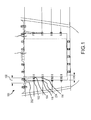
- Commonly used pallet widths are the W1 pallet that has a width of 108" and a W2 pallet that has a width of 125.”
- a W2 pallet is labeled as pallet 2 and is shown overlayed with W1 pallet labeled as pallet 1.
- guide assembly 202 in position 102 is shown in a configuration to accept pallet 2
- guide assembly 202 in position 104 is shown in a configuration to accept pallet 1.
- the difference in width between the configuration for pallet 1 and pallet 2 of guide assembly 202 is shown as distance 108.
- Restraint assemblies 204 in position 118 are shown in a configuration to accept pallet 2 and restraint assemblies 204 in position 116 are shown in a configuration to accept pallet 1.
- the difference in width between the configuration for pallet 1 and pallet 2 of restraint assemblies 204 is shown as distance 106.
- pallet 206 is shown engaging with guide assembly 202.
- the incline of sliding rail of guide assembly 202 interacts with pallet 206 to position the pallet with respect to restraint assemblies 204.
- Guide assembly 202 and restraint assemblies 204 are shown fixed to an aircraft, for example, an aircraft floor and/or other attachment features that couple guide assembly 202 and restraint assemblies 204 to the aircraft.
- Guide assembly 202 is shown forward of restraint assemblies 204.
- Guide assembly 202 comprises sliding rail 402, first fitting 304 and second fitting 306.
- Restraint assembly 204 comprises restraint fitting 308 and rail 310.
- First fitting 304, second fitting 306 and restraint fitting 308 are mounted to aircraft floor 312. In that regard, first fitting 304, second fitting 306 and restraint fitting 308 may be considered mounted portions.
- the sliding rail 302 of guide assembly 202 and rail 310 of restraint assemblies 204 may be moved inward or outward while first fitting 304, second fitting 306 and restraint fitting 308 remain fixed with respect to aircraft floor 312.
- the sliding rail 302 of guide assembly 202 and rail 310 of restraint assemblies 204 may be considered slidable portions.
- a first position 250 is shown along with second position 252. The difference between first position 250 and first position 250 is distance D.
- distance D may be between 0.5 inches ( ⁇ 1.27 cm) and 6 inches ( ⁇ 15.24 cm), between 1 inch ( ⁇ 2.54 cm) and 4 inches ( ⁇ 10.16 cm), and about 2.5 inches ( ⁇ 6.35 cm), where the term "about” in this context only means +/- 0.2 inches ( ⁇ 0.5 cm).
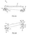
- guide assembly 202 is illustrated.
- Sliding rail 402 is shown engaged with first fitting 304 and second fitting 306 in FIGs. 3 , 4A and 4B and disengaged from first fitting 304 and second fitting 306 in FIG. 4C .
- Sliding rail 402 comprises channels 416 and 420.
- a channel in sliding rail 402 may be any aperture, cutout, or other opening in sliding rail 402.
- the interior portion of channels 416 and 420 may comprise one or more retaining features such as retaining tabs, notches, grooves, threads, or other suitable features.
- channels 416 and 420 each comprise an inverse T shape.
- each of channels 416 and 420 comprise two retaining tabs.
- Channel 416 for example, includes two retaining tabs 480 and 482 that are configured to mate to a T shaped rail.
- the retaining tabs 480 and 482 are configured to mate to a T shaped rail and restrain sliding rail 402 from separation from, for example, first fitting 304.
- Channel 420 includes two retaining tabs 484 and 486 that are configured to mate to a T shaped rail.
- the retaining tabs 484 and 486 are configured to mate to a T shaped rail and restrain sliding rail 402 from separation from, for example, second fitting 306.
- the retaining tabs 484, 486 and 480, 482 are configured to mate to a T shaped rail and restrain sliding rail 402 in a z direction.
- First fitting 304 comprises first retaining rail 418 and second fitting 306 comprises second retaining rail 422.
- Both first retaining rail 418 and second retaining rail 422 comprise a T shape.
- first retaining rail 418 and second retaining rail 422 may comprise any suitable geometry that is configured to mate with channels 416 and 420.
- First retaining rail 418 and second retaining rail 422 may comprise a depression 430.
- Depression 430 may comprise an indentation or similar feature extending in the z direction.
- a bolt from a shear kit 432 may be disposed in counterbore 412 of sliding rail 402.
- Counterbore 412 may comprise an indentation in sliding rail 402 and an aperture that proceeds through sliding rail 402.
- a bolt from a shear kit 432 may be disposed in counterbore 412 and pass into depression 430.
- the shear kit 432 may be appropriately torqued to couple sliding rail 402 to second retaining rail 422 of second fitting 306.
- Sliding rail 402 may comprise angle 410.
- Angle 410 may assist in the positioning of cargo within an aircraft. In various embodiments, angle 410 may be between 5 degrees and 15 degrees.
- a bolt from a shear kit 450 may be disposed in counterbore 452 of sliding rail 402.
- Counterbore 452 may comprise an indentation in sliding rail 402 and an aperture that proceeds through sliding rail 402.
- a bolt from a shear kit 450 may be disposed in counterbore 452 and pass into depression 456 on first retaining rail 418 of first fitting 304.
- the shear kit 450 may be appropriately torqued to couple sliding rail 402 to first retaining rail 418 of first fitting 304.
- First fitting 304 may comprise shear kit 454 that may couple first fitting 304 to an aircraft.
- Second fitting 306 may comprise shear kit 424 that may couple second fitting 306 to an aircraft.
- Guide assembly 202 is thus able to quickly and easily adapt to accept different sized pallets, for example, pallet 1 and pallet 2 shown in FIG. 1 .
- sliding rail 402 may engage with and slide with respect to first retaining rail 418 of first fitting 304 and second retaining rail 422 of second fitting 306.
- a bolt from a shear kit 450 may be disposed in counterbore 452 and pass into depression 456 on first retaining rail 418 of first fitting 304. The bolt may be torqued, thereby restraining sliding rail 402 from sliding with respect to first fitting 304. In this manner, an aircraft cargo management system may adapt to accept different sized pallets more easily.
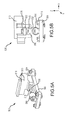
- restraint assembly 500 is shown in an assembled state ( FIG. 5A ) and an unassembled state ( FIG. 5B ).
- Restraint assembly 500 comprises restraint fitting 308 and rail 310, as also shown in FIG. 3 .
- Rail 310 comprises channel 512.
- Channel 512 in rail 310 may be any aperture, cutout, or other opening in rail 310.
- the interior portion of channel 512 may comprise one or more retaining features such as retaining tabs, notches, grooves, threads, or other suitable features.
- channel 512 comprises an inverse T shape.
- channel 512 comprises two retaining tabs 550 and 552.
- Channel 512 for example, includes two retaining tabs 550 and 552 that are configured to mate to a T shaped rail.
- the retaining tabs 550 and 552 are configured to mate to a T shaped rail and restrain restraint assembly 500 from separation from, for example, restraint fitting 308.
- the retaining tabs 550 and 552 are configured to mate to a T shaped rail and restrain rail 310 in a z direction.
- Restraint fitting 308 comprises first retaining rail 514.
- First retaining rail 514 comprises a T shape.
- first retaining rail 514 may comprise any suitable geometry that is configured to mate with channel 512.
- First retaining rail 514 may comprise a depression 510.
- Depression 510 may comprise an indentation or similar feature extending in the z direction.
- a bolt from a shear kit 520 may be disposed in aperture 522 of rail 310.
- Aperture 522 may proceed through rail 310.
- a bolt from a shear kit 520 may be disposed in aperture 522 and may pass into depression 510.
- the shear kit 520 may be appropriately torqued to couple rail 310 to restraint fitting 308.
- Shear kit 516 may secure restraint fitting 308 to an aircraft.
- Rail 310 may comprise lip 518.
- Lip 518 may be configured to seat over a pallet of cargo.
- lip 518 may restrain the movement of cargo in a Z direction in that a force in the Z direction on the cargo would be carried by the lip 518 through rail 310 and to the restraint fitting 308.
- Restraint fitting 308 may also comprise roller 506 to assist in moving cargo.
- Restraint assembly 500 is thus able to quickly and easily adapt to accept different sized pallets, for example, pallet 1 and pallet 2 shown in FIG. 1 .
- rail 310 may engage with and slide with respect to retaining rail 514.
- a bolt from shear kit 520 may be appropriately torqued to couple rail 310 to restraint fitting 308, thereby restraining rail 310 from sliding with respect to restraint fitting 308.
- an aircraft cargo management system may adapt to accept different sized pallets more easily.
- references to "one embodiment”, “an embodiment”, “various embodiments”, etc. indicate that the embodiment described may include a particular feature, structure, or characteristic, but every embodiment may not necessarily include the particular feature, structure, or characteristic. Moreover, such phrases are not necessarily referring to the same embodiment. Further, when a particular feature, structure, or characteristic is described in connection with an embodiment, it is submitted that it is within the knowledge of one skilled in the art to affect such feature, structure, or characteristic in connection with other embodiments whether or not explicitly described. After reading the description, it will be apparent to one skilled in the relevant art(s) how to implement the disclosure in alternative embodiments.
Priority Applications (1)
| Application Number | Priority Date | Filing Date | Title |
|---|---|---|---|
| EP21160840.1A EP3848283B1 (fr) | 2014-10-08 | 2015-10-07 | Ensembles de retenue réglables |
Applications Claiming Priority (1)
| Application Number | Priority Date | Filing Date | Title |
|---|---|---|---|
| US14/509,713 US9475581B2 (en) | 2014-10-08 | 2014-10-08 | Adjustable restraint assemblies |
Related Child Applications (2)
| Application Number | Title | Priority Date | Filing Date |
|---|---|---|---|
| EP21160840.1A Division EP3848283B1 (fr) | 2014-10-08 | 2015-10-07 | Ensembles de retenue réglables |
| EP21160840.1A Division-Into EP3848283B1 (fr) | 2014-10-08 | 2015-10-07 | Ensembles de retenue réglables |
Publications (3)
| Publication Number | Publication Date |
|---|---|
| EP3006336A2 true EP3006336A2 (fr) | 2016-04-13 |
| EP3006336A3 EP3006336A3 (fr) | 2016-07-13 |
| EP3006336B1 EP3006336B1 (fr) | 2021-04-14 |
Family
ID=54291116
Family Applications (2)
| Application Number | Title | Priority Date | Filing Date |
|---|---|---|---|
| EP21160840.1A Active EP3848283B1 (fr) | 2014-10-08 | 2015-10-07 | Ensembles de retenue réglables |
| EP15188720.5A Active EP3006336B1 (fr) | 2014-10-08 | 2015-10-07 | Ensembles de retenue réglables |
Family Applications Before (1)
| Application Number | Title | Priority Date | Filing Date |
|---|---|---|---|
| EP21160840.1A Active EP3848283B1 (fr) | 2014-10-08 | 2015-10-07 | Ensembles de retenue réglables |
Country Status (2)
| Country | Link |
|---|---|
| US (2) | US9475581B2 (fr) |
| EP (2) | EP3848283B1 (fr) |
Families Citing this family (7)
| Publication number | Priority date | Publication date | Assignee | Title |
|---|---|---|---|---|
| GB201322367D0 (en) * | 2013-12-18 | 2014-02-05 | Mcgriskin Ideas Ltd | Spacer block system |
| US9475581B2 (en) * | 2014-10-08 | 2016-10-25 | Goodrich Corporation | Adjustable restraint assemblies |
| EP3156329B1 (fr) * | 2015-10-14 | 2018-08-15 | Airbus Operations GmbH | Système pour déplacer des charges et conteneur de cargaison |
| US10017251B2 (en) * | 2016-06-06 | 2018-07-10 | Ancra International, Llc | Cargo restraint for aircraft |
| US10375796B2 (en) * | 2017-04-25 | 2019-08-06 | Current Lighting Solutions, Llc | Waveform shaping circuit for spurious harmonic suppression |
| US10793053B2 (en) | 2018-10-03 | 2020-10-06 | Dusty Smith | Load securing assembly |
| US11897629B2 (en) | 2019-12-17 | 2024-02-13 | Goodrich Corporation | Cargo handling system repositionable side guide |
Family Cites Families (15)
| Publication number | Priority date | Publication date | Assignee | Title |
|---|---|---|---|---|
| US3168205A (en) * | 1963-03-08 | 1965-02-02 | Green Sherwood | Mobile platform incorporating elevationally adjustable conveyor |
| DE2432245B2 (de) * | 1974-07-05 | 1976-07-01 | Messerschmitt-Bölkow-Blohm GmbH, 8000 München | Ueberrollbare vorrichtung zum verriegeln von frachttraegern |
| DE3107745A1 (de) * | 1981-02-28 | 1982-09-16 | Vereinigte Flugtechnische Werke Gmbh, 2800 Bremen | Riegelelement fuer ein frachtladesystem |
| US4530483A (en) * | 1982-09-30 | 1985-07-23 | Ancra Corporation | Side guide for cargo loading system |
| US4700923A (en) * | 1983-05-19 | 1987-10-20 | Lewis Jr Irvin H | Universal, portable, concrete slab base for pump jacks |
| JPS601411A (ja) * | 1983-06-15 | 1985-01-07 | スガツネ工業株式会社 | フリ−ストツプ受具 |
| US5310297A (en) * | 1992-08-27 | 1994-05-10 | Federal Express Corporation | Cargo restraint apparatus and system |
| US5692862A (en) * | 1996-06-27 | 1997-12-02 | The Boeing Company | Knock down cargo guide rail |
| US6312034B1 (en) * | 1999-11-23 | 2001-11-06 | Mink & Associates Llc | Vehicle bed and cargo area liner with integrated sliding floor extension |
| US6260813B1 (en) * | 2000-01-10 | 2001-07-17 | November Whiskey, Inc. | Aircraft seat track anchor fitting |
| US6425717B1 (en) * | 2000-11-08 | 2002-07-30 | The Boeing Company | Cargo restraint device |
| US7665938B2 (en) * | 2006-03-30 | 2010-02-23 | Goodrich Corporation | Coaxially mounted retracting guide and restraint for an air cargo system |
| US7665939B1 (en) * | 2006-08-10 | 2010-02-23 | Sure—Lok, Inc. | Retractor anchor with top release |
| DE102010036983B4 (de) * | 2010-08-13 | 2012-05-03 | Telair International Gmbh | Seitenführung, Seitenführungsgruppe, Frachtdeck |
| US9475581B2 (en) * | 2014-10-08 | 2016-10-25 | Goodrich Corporation | Adjustable restraint assemblies |
-
2014
- 2014-10-08 US US14/509,713 patent/US9475581B2/en active Active
-
2015
- 2015-10-07 EP EP21160840.1A patent/EP3848283B1/fr active Active
- 2015-10-07 EP EP15188720.5A patent/EP3006336B1/fr active Active
-
2016
- 2016-09-21 US US15/272,171 patent/US9809309B2/en active Active
Non-Patent Citations (1)
| Title |
|---|
| None |
Also Published As
| Publication number | Publication date |
|---|---|
| US20170008628A1 (en) | 2017-01-12 |
| US9475581B2 (en) | 2016-10-25 |
| US9809309B2 (en) | 2017-11-07 |
| EP3848283B1 (fr) | 2023-06-07 |
| US20160101864A1 (en) | 2016-04-14 |
| EP3006336A3 (fr) | 2016-07-13 |
| EP3848283A1 (fr) | 2021-07-14 |
| EP3006336B1 (fr) | 2021-04-14 |
Similar Documents
| Publication | Publication Date | Title |
|---|---|---|
| EP3006336A2 (fr) | Ensembles de retenue réglables | |
| US8136766B2 (en) | Frangible fasteners for aircraft components and associated systems and methods | |
| US9205923B1 (en) | Manual override cargo unloading system for air cushion supported aircraft cargo loading robot | |
| EP2507128B1 (fr) | Plancher de soute d'avion, element fonctionnel a integrer dans un plancher de soute, element de guidage lateral, dispositif de fixation permettant d'induire un effort de traction et dispositif permettant de larguer des elements de cargaison | |
| WO2015148690A1 (fr) | Système de fixation | |
| EP3186520B1 (fr) | Dispositif de fixation borgne amovible pour relier des éléments | |
| EP3241739A1 (fr) | Système de fixation mécanique et ensemble structurel associé et procédé | |
| US10377572B1 (en) | Moveable integrated side guide and roller tray assembly for cargo management system | |
| EP3666652A1 (fr) | Raccord de piste à verrouillage à libération rapide pour siège d'aéronef | |
| US9481445B2 (en) | Connection device for means of airplane | |
| DE102018205880B3 (de) | Vorrichtung für ein Fahrzeug zur Übernahme eines Objektes bei einer Drohnenlieferung | |
| US10414480B2 (en) | Sidewall mounting hardware for aircraft | |
| US10137978B2 (en) | Folding wing tip device with rotatable lock | |
| US20160001870A1 (en) | Method for loading cargo into an aircraft | |
| US9944381B2 (en) | Load transfer apparatus for transferring loads in an aircraft structure | |
| EP3778302B1 (fr) | Guide de chargement escamotable pour plateaux de chargement à rouleaux | |
| US20190277443A1 (en) | Brackets and Assemblies for Attaching Objects to Surfaces in Vehicles | |
| US11708165B2 (en) | Rail arrangement for an inner space of an aircraft | |
| US9545990B2 (en) | Floor panel retention system | |
| EP3254896B1 (fr) | Rail de fixation | |
| US20190131781A1 (en) | Bend radius device for flexible tube | |
| DE102013214776B4 (de) | Rumpfstruktur eines Luft- und/oder Raumfahrzeugs sowie Verfahren | |
| WO2017089926A1 (fr) | Œillet | |
| GB2545695A (en) | Cable segregation device |
Legal Events
| Date | Code | Title | Description |
|---|---|---|---|
| PUAI | Public reference made under article 153(3) epc to a published international application that has entered the european phase |
Free format text: ORIGINAL CODE: 0009012 |
|
| AK | Designated contracting states |
Kind code of ref document: A2 Designated state(s): AL AT BE BG CH CY CZ DE DK EE ES FI FR GB GR HR HU IE IS IT LI LT LU LV MC MK MT NL NO PL PT RO RS SE SI SK SM TR |
|
| AX | Request for extension of the european patent |
Extension state: BA ME |
|
| PUAL | Search report despatched |
Free format text: ORIGINAL CODE: 0009013 |
|
| AK | Designated contracting states |
Kind code of ref document: A3 Designated state(s): AL AT BE BG CH CY CZ DE DK EE ES FI FR GB GR HR HU IE IS IT LI LT LU LV MC MK MT NL NO PL PT RO RS SE SI SK SM TR |
|
| AX | Request for extension of the european patent |
Extension state: BA ME |
|
| RIC1 | Information provided on ipc code assigned before grant |
Ipc: B64D 9/00 20060101AFI20160603BHEP |
|
| STAA | Information on the status of an ep patent application or granted ep patent |
Free format text: STATUS: REQUEST FOR EXAMINATION WAS MADE |
|
| 17P | Request for examination filed |
Effective date: 20170113 |
|
| RBV | Designated contracting states (corrected) |
Designated state(s): AL AT BE BG CH CY CZ DE DK EE ES FI FR GB GR HR HU IE IS IT LI LT LU LV MC MK MT NL NO PL PT RO RS SE SI SK SM TR |
|
| STAA | Information on the status of an ep patent application or granted ep patent |
Free format text: STATUS: EXAMINATION IS IN PROGRESS |
|
| 17Q | First examination report despatched |
Effective date: 20181102 |
|
| GRAP | Despatch of communication of intention to grant a patent |
Free format text: ORIGINAL CODE: EPIDOSNIGR1 |
|
| STAA | Information on the status of an ep patent application or granted ep patent |
Free format text: STATUS: GRANT OF PATENT IS INTENDED |
|
| INTG | Intention to grant announced |
Effective date: 20201027 |
|
| GRAS | Grant fee paid |
Free format text: ORIGINAL CODE: EPIDOSNIGR3 |
|
| GRAA | (expected) grant |
Free format text: ORIGINAL CODE: 0009210 |
|
| STAA | Information on the status of an ep patent application or granted ep patent |
Free format text: STATUS: THE PATENT HAS BEEN GRANTED |
|
| AK | Designated contracting states |
Kind code of ref document: B1 Designated state(s): AL AT BE BG CH CY CZ DE DK EE ES FI FR GB GR HR HU IE IS IT LI LT LU LV MC MK MT NL NO PL PT RO RS SE SI SK SM TR |
|
| REG | Reference to a national code |
Ref country code: GB Ref legal event code: FG4D |
|
| REG | Reference to a national code |
Ref country code: CH Ref legal event code: EP |
|
| REG | Reference to a national code |
Ref country code: DE Ref legal event code: R096 Ref document number: 602015068033 Country of ref document: DE |
|
| REG | Reference to a national code |
Ref country code: IE Ref legal event code: FG4D |
|
| REG | Reference to a national code |
Ref country code: AT Ref legal event code: REF Ref document number: 1382156 Country of ref document: AT Kind code of ref document: T Effective date: 20210515 |
|
| REG | Reference to a national code |
Ref country code: LT Ref legal event code: MG9D |
|
| REG | Reference to a national code |
Ref country code: AT Ref legal event code: MK05 Ref document number: 1382156 Country of ref document: AT Kind code of ref document: T Effective date: 20210414 |
|
| REG | Reference to a national code |
Ref country code: NL Ref legal event code: MP Effective date: 20210414 |
|
| PG25 | Lapsed in a contracting state [announced via postgrant information from national office to epo] |
Ref country code: HR Free format text: LAPSE BECAUSE OF FAILURE TO SUBMIT A TRANSLATION OF THE DESCRIPTION OR TO PAY THE FEE WITHIN THE PRESCRIBED TIME-LIMIT Effective date: 20210414 Ref country code: AT Free format text: LAPSE BECAUSE OF FAILURE TO SUBMIT A TRANSLATION OF THE DESCRIPTION OR TO PAY THE FEE WITHIN THE PRESCRIBED TIME-LIMIT Effective date: 20210414 Ref country code: BG Free format text: LAPSE BECAUSE OF FAILURE TO SUBMIT A TRANSLATION OF THE DESCRIPTION OR TO PAY THE FEE WITHIN THE PRESCRIBED TIME-LIMIT Effective date: 20210714 Ref country code: FI Free format text: LAPSE BECAUSE OF FAILURE TO SUBMIT A TRANSLATION OF THE DESCRIPTION OR TO PAY THE FEE WITHIN THE PRESCRIBED TIME-LIMIT Effective date: 20210414 Ref country code: LT Free format text: LAPSE BECAUSE OF FAILURE TO SUBMIT A TRANSLATION OF THE DESCRIPTION OR TO PAY THE FEE WITHIN THE PRESCRIBED TIME-LIMIT Effective date: 20210414 Ref country code: NL Free format text: LAPSE BECAUSE OF FAILURE TO SUBMIT A TRANSLATION OF THE DESCRIPTION OR TO PAY THE FEE WITHIN THE PRESCRIBED TIME-LIMIT Effective date: 20210414 |
|
| PG25 | Lapsed in a contracting state [announced via postgrant information from national office to epo] |
Ref country code: IS Free format text: LAPSE BECAUSE OF FAILURE TO SUBMIT A TRANSLATION OF THE DESCRIPTION OR TO PAY THE FEE WITHIN THE PRESCRIBED TIME-LIMIT Effective date: 20210814 Ref country code: GR Free format text: LAPSE BECAUSE OF FAILURE TO SUBMIT A TRANSLATION OF THE DESCRIPTION OR TO PAY THE FEE WITHIN THE PRESCRIBED TIME-LIMIT Effective date: 20210715 Ref country code: LV Free format text: LAPSE BECAUSE OF FAILURE TO SUBMIT A TRANSLATION OF THE DESCRIPTION OR TO PAY THE FEE WITHIN THE PRESCRIBED TIME-LIMIT Effective date: 20210414 Ref country code: NO Free format text: LAPSE BECAUSE OF FAILURE TO SUBMIT A TRANSLATION OF THE DESCRIPTION OR TO PAY THE FEE WITHIN THE PRESCRIBED TIME-LIMIT Effective date: 20210714 Ref country code: PT Free format text: LAPSE BECAUSE OF FAILURE TO SUBMIT A TRANSLATION OF THE DESCRIPTION OR TO PAY THE FEE WITHIN THE PRESCRIBED TIME-LIMIT Effective date: 20210816 Ref country code: PL Free format text: LAPSE BECAUSE OF FAILURE TO SUBMIT A TRANSLATION OF THE DESCRIPTION OR TO PAY THE FEE WITHIN THE PRESCRIBED TIME-LIMIT Effective date: 20210414 Ref country code: ES Free format text: LAPSE BECAUSE OF FAILURE TO SUBMIT A TRANSLATION OF THE DESCRIPTION OR TO PAY THE FEE WITHIN THE PRESCRIBED TIME-LIMIT Effective date: 20210414 Ref country code: RS Free format text: LAPSE BECAUSE OF FAILURE TO SUBMIT A TRANSLATION OF THE DESCRIPTION OR TO PAY THE FEE WITHIN THE PRESCRIBED TIME-LIMIT Effective date: 20210414 Ref country code: SE Free format text: LAPSE BECAUSE OF FAILURE TO SUBMIT A TRANSLATION OF THE DESCRIPTION OR TO PAY THE FEE WITHIN THE PRESCRIBED TIME-LIMIT Effective date: 20210414 |
|
| REG | Reference to a national code |
Ref country code: DE Ref legal event code: R097 Ref document number: 602015068033 Country of ref document: DE |
|
| PG25 | Lapsed in a contracting state [announced via postgrant information from national office to epo] |
Ref country code: SM Free format text: LAPSE BECAUSE OF FAILURE TO SUBMIT A TRANSLATION OF THE DESCRIPTION OR TO PAY THE FEE WITHIN THE PRESCRIBED TIME-LIMIT Effective date: 20210414 Ref country code: SK Free format text: LAPSE BECAUSE OF FAILURE TO SUBMIT A TRANSLATION OF THE DESCRIPTION OR TO PAY THE FEE WITHIN THE PRESCRIBED TIME-LIMIT Effective date: 20210414 Ref country code: DK Free format text: LAPSE BECAUSE OF FAILURE TO SUBMIT A TRANSLATION OF THE DESCRIPTION OR TO PAY THE FEE WITHIN THE PRESCRIBED TIME-LIMIT Effective date: 20210414 Ref country code: EE Free format text: LAPSE BECAUSE OF FAILURE TO SUBMIT A TRANSLATION OF THE DESCRIPTION OR TO PAY THE FEE WITHIN THE PRESCRIBED TIME-LIMIT Effective date: 20210414 Ref country code: CZ Free format text: LAPSE BECAUSE OF FAILURE TO SUBMIT A TRANSLATION OF THE DESCRIPTION OR TO PAY THE FEE WITHIN THE PRESCRIBED TIME-LIMIT Effective date: 20210414 Ref country code: RO Free format text: LAPSE BECAUSE OF FAILURE TO SUBMIT A TRANSLATION OF THE DESCRIPTION OR TO PAY THE FEE WITHIN THE PRESCRIBED TIME-LIMIT Effective date: 20210414 |
|
| PLBE | No opposition filed within time limit |
Free format text: ORIGINAL CODE: 0009261 |
|
| STAA | Information on the status of an ep patent application or granted ep patent |
Free format text: STATUS: NO OPPOSITION FILED WITHIN TIME LIMIT |
|
| 26N | No opposition filed |
Effective date: 20220117 |
|
| REG | Reference to a national code |
Ref country code: CH Ref legal event code: PL |
|
| PG25 | Lapsed in a contracting state [announced via postgrant information from national office to epo] |
Ref country code: IS Free format text: LAPSE BECAUSE OF FAILURE TO SUBMIT A TRANSLATION OF THE DESCRIPTION OR TO PAY THE FEE WITHIN THE PRESCRIBED TIME-LIMIT Effective date: 20210814 Ref country code: AL Free format text: LAPSE BECAUSE OF FAILURE TO SUBMIT A TRANSLATION OF THE DESCRIPTION OR TO PAY THE FEE WITHIN THE PRESCRIBED TIME-LIMIT Effective date: 20210414 |
|
| REG | Reference to a national code |
Ref country code: BE Ref legal event code: MM Effective date: 20211031 |
|
| GBPC | Gb: european patent ceased through non-payment of renewal fee |
Effective date: 20211007 |
|
| PG25 | Lapsed in a contracting state [announced via postgrant information from national office to epo] |
Ref country code: MC Free format text: LAPSE BECAUSE OF FAILURE TO SUBMIT A TRANSLATION OF THE DESCRIPTION OR TO PAY THE FEE WITHIN THE PRESCRIBED TIME-LIMIT Effective date: 20210414 |
|
| PG25 | Lapsed in a contracting state [announced via postgrant information from national office to epo] |
Ref country code: LU Free format text: LAPSE BECAUSE OF NON-PAYMENT OF DUE FEES Effective date: 20211007 Ref country code: IT Free format text: LAPSE BECAUSE OF FAILURE TO SUBMIT A TRANSLATION OF THE DESCRIPTION OR TO PAY THE FEE WITHIN THE PRESCRIBED TIME-LIMIT Effective date: 20210414 Ref country code: GB Free format text: LAPSE BECAUSE OF NON-PAYMENT OF DUE FEES Effective date: 20211007 Ref country code: BE Free format text: LAPSE BECAUSE OF NON-PAYMENT OF DUE FEES Effective date: 20211031 |
|
| PG25 | Lapsed in a contracting state [announced via postgrant information from national office to epo] |
Ref country code: LI Free format text: LAPSE BECAUSE OF NON-PAYMENT OF DUE FEES Effective date: 20211031 Ref country code: CH Free format text: LAPSE BECAUSE OF NON-PAYMENT OF DUE FEES Effective date: 20211031 |
|
| PG25 | Lapsed in a contracting state [announced via postgrant information from national office to epo] |
Ref country code: IE Free format text: LAPSE BECAUSE OF NON-PAYMENT OF DUE FEES Effective date: 20211007 |
|
| PG25 | Lapsed in a contracting state [announced via postgrant information from national office to epo] |
Ref country code: HU Free format text: LAPSE BECAUSE OF FAILURE TO SUBMIT A TRANSLATION OF THE DESCRIPTION OR TO PAY THE FEE WITHIN THE PRESCRIBED TIME-LIMIT; INVALID AB INITIO Effective date: 20151007 |
|
| P01 | Opt-out of the competence of the unified patent court (upc) registered |
Effective date: 20230522 |
|
| PG25 | Lapsed in a contracting state [announced via postgrant information from national office to epo] |
Ref country code: CY Free format text: LAPSE BECAUSE OF FAILURE TO SUBMIT A TRANSLATION OF THE DESCRIPTION OR TO PAY THE FEE WITHIN THE PRESCRIBED TIME-LIMIT Effective date: 20210414 |
|
| PGFP | Annual fee paid to national office [announced via postgrant information from national office to epo] |
Ref country code: FR Payment date: 20230920 Year of fee payment: 9 |
|
| PGFP | Annual fee paid to national office [announced via postgrant information from national office to epo] |
Ref country code: DE Payment date: 20230920 Year of fee payment: 9 |
|
| PG25 | Lapsed in a contracting state [announced via postgrant information from national office to epo] |
Ref country code: MK Free format text: LAPSE BECAUSE OF FAILURE TO SUBMIT A TRANSLATION OF THE DESCRIPTION OR TO PAY THE FEE WITHIN THE PRESCRIBED TIME-LIMIT Effective date: 20210414 |