EP3006245A1 - Getriebesteuerverfahren - Google Patents
Getriebesteuerverfahren Download PDFInfo
- Publication number
- EP3006245A1 EP3006245A1 EP15185916.2A EP15185916A EP3006245A1 EP 3006245 A1 EP3006245 A1 EP 3006245A1 EP 15185916 A EP15185916 A EP 15185916A EP 3006245 A1 EP3006245 A1 EP 3006245A1
- Authority
- EP
- European Patent Office
- Prior art keywords
- power
- electric
- electric machine
- gear
- transmission
- Prior art date
- Legal status (The legal status is an assumption and is not a legal conclusion. Google has not performed a legal analysis and makes no representation as to the accuracy of the status listed.)
- Granted
Links
Images




Classifications
-
- F—MECHANICAL ENGINEERING; LIGHTING; HEATING; WEAPONS; BLASTING
- F16—ENGINEERING ELEMENTS AND UNITS; GENERAL MEASURES FOR PRODUCING AND MAINTAINING EFFECTIVE FUNCTIONING OF MACHINES OR INSTALLATIONS; THERMAL INSULATION IN GENERAL
- F16H—GEARING
- F16H3/00—Toothed gearings for conveying rotary motion with variable gear ratio or for reversing rotary motion
- F16H3/44—Toothed gearings for conveying rotary motion with variable gear ratio or for reversing rotary motion using gears having orbital motion
- F16H3/72—Toothed gearings for conveying rotary motion with variable gear ratio or for reversing rotary motion using gears having orbital motion with a secondary drive, e.g. regulating motor, in order to vary speed continuously
- F16H3/727—Toothed gearings for conveying rotary motion with variable gear ratio or for reversing rotary motion using gears having orbital motion with a secondary drive, e.g. regulating motor, in order to vary speed continuously with at least two dynamo electric machines for creating an electric power path inside the gearing, e.g. using generator and motor for a variable power torque path
- F16H3/728—Toothed gearings for conveying rotary motion with variable gear ratio or for reversing rotary motion using gears having orbital motion with a secondary drive, e.g. regulating motor, in order to vary speed continuously with at least two dynamo electric machines for creating an electric power path inside the gearing, e.g. using generator and motor for a variable power torque path with means to change ratio in the mechanical gearing
-
- A—HUMAN NECESSITIES
- A01—AGRICULTURE; FORESTRY; ANIMAL HUSBANDRY; HUNTING; TRAPPING; FISHING
- A01B—SOIL WORKING IN AGRICULTURE OR FORESTRY; PARTS, DETAILS, OR ACCESSORIES OF AGRICULTURAL MACHINES OR IMPLEMENTS, IN GENERAL
- A01B61/00—Devices for, or parts of, agricultural machines or implements for preventing overstrain
-
- B—PERFORMING OPERATIONS; TRANSPORTING
- B60—VEHICLES IN GENERAL
- B60K—ARRANGEMENT OR MOUNTING OF PROPULSION UNITS OR OF TRANSMISSIONS IN VEHICLES; ARRANGEMENT OR MOUNTING OF PLURAL DIVERSE PRIME-MOVERS IN VEHICLES; AUXILIARY DRIVES FOR VEHICLES; INSTRUMENTATION OR DASHBOARDS FOR VEHICLES; ARRANGEMENTS IN CONNECTION WITH COOLING, AIR INTAKE, GAS EXHAUST OR FUEL SUPPLY OF PROPULSION UNITS IN VEHICLES
- B60K6/00—Arrangement or mounting of plural diverse prime-movers for mutual or common propulsion, e.g. hybrid propulsion systems comprising electric motors and internal combustion engines
- B60K6/20—Arrangement or mounting of plural diverse prime-movers for mutual or common propulsion, e.g. hybrid propulsion systems comprising electric motors and internal combustion engines the prime-movers consisting of electric motors and internal combustion engines, e.g. HEVs
- B60K6/22—Arrangement or mounting of plural diverse prime-movers for mutual or common propulsion, e.g. hybrid propulsion systems comprising electric motors and internal combustion engines the prime-movers consisting of electric motors and internal combustion engines, e.g. HEVs characterised by apparatus, components or means specially adapted for HEVs
- B60K6/36—Arrangement or mounting of plural diverse prime-movers for mutual or common propulsion, e.g. hybrid propulsion systems comprising electric motors and internal combustion engines the prime-movers consisting of electric motors and internal combustion engines, e.g. HEVs characterised by apparatus, components or means specially adapted for HEVs characterised by the transmission gearings
- B60K6/365—Arrangement or mounting of plural diverse prime-movers for mutual or common propulsion, e.g. hybrid propulsion systems comprising electric motors and internal combustion engines the prime-movers consisting of electric motors and internal combustion engines, e.g. HEVs characterised by apparatus, components or means specially adapted for HEVs characterised by the transmission gearings with the gears having orbital motion
-
- B—PERFORMING OPERATIONS; TRANSPORTING
- B60—VEHICLES IN GENERAL
- B60K—ARRANGEMENT OR MOUNTING OF PROPULSION UNITS OR OF TRANSMISSIONS IN VEHICLES; ARRANGEMENT OR MOUNTING OF PLURAL DIVERSE PRIME-MOVERS IN VEHICLES; AUXILIARY DRIVES FOR VEHICLES; INSTRUMENTATION OR DASHBOARDS FOR VEHICLES; ARRANGEMENTS IN CONNECTION WITH COOLING, AIR INTAKE, GAS EXHAUST OR FUEL SUPPLY OF PROPULSION UNITS IN VEHICLES
- B60K6/00—Arrangement or mounting of plural diverse prime-movers for mutual or common propulsion, e.g. hybrid propulsion systems comprising electric motors and internal combustion engines
- B60K6/20—Arrangement or mounting of plural diverse prime-movers for mutual or common propulsion, e.g. hybrid propulsion systems comprising electric motors and internal combustion engines the prime-movers consisting of electric motors and internal combustion engines, e.g. HEVs
- B60K6/22—Arrangement or mounting of plural diverse prime-movers for mutual or common propulsion, e.g. hybrid propulsion systems comprising electric motors and internal combustion engines the prime-movers consisting of electric motors and internal combustion engines, e.g. HEVs characterised by apparatus, components or means specially adapted for HEVs
- B60K6/38—Arrangement or mounting of plural diverse prime-movers for mutual or common propulsion, e.g. hybrid propulsion systems comprising electric motors and internal combustion engines the prime-movers consisting of electric motors and internal combustion engines, e.g. HEVs characterised by apparatus, components or means specially adapted for HEVs characterised by the driveline clutches
- B60K6/387—Actuated clutches, i.e. clutches engaged or disengaged by electric, hydraulic or mechanical actuating means
-
- B—PERFORMING OPERATIONS; TRANSPORTING
- B60—VEHICLES IN GENERAL
- B60K—ARRANGEMENT OR MOUNTING OF PROPULSION UNITS OR OF TRANSMISSIONS IN VEHICLES; ARRANGEMENT OR MOUNTING OF PLURAL DIVERSE PRIME-MOVERS IN VEHICLES; AUXILIARY DRIVES FOR VEHICLES; INSTRUMENTATION OR DASHBOARDS FOR VEHICLES; ARRANGEMENTS IN CONNECTION WITH COOLING, AIR INTAKE, GAS EXHAUST OR FUEL SUPPLY OF PROPULSION UNITS IN VEHICLES
- B60K6/00—Arrangement or mounting of plural diverse prime-movers for mutual or common propulsion, e.g. hybrid propulsion systems comprising electric motors and internal combustion engines
- B60K6/20—Arrangement or mounting of plural diverse prime-movers for mutual or common propulsion, e.g. hybrid propulsion systems comprising electric motors and internal combustion engines the prime-movers consisting of electric motors and internal combustion engines, e.g. HEVs
- B60K6/42—Arrangement or mounting of plural diverse prime-movers for mutual or common propulsion, e.g. hybrid propulsion systems comprising electric motors and internal combustion engines the prime-movers consisting of electric motors and internal combustion engines, e.g. HEVs characterised by the architecture of the hybrid electric vehicle
- B60K6/44—Series-parallel type
- B60K6/445—Differential gearing distribution type
-
- B—PERFORMING OPERATIONS; TRANSPORTING
- B60—VEHICLES IN GENERAL
- B60K—ARRANGEMENT OR MOUNTING OF PROPULSION UNITS OR OF TRANSMISSIONS IN VEHICLES; ARRANGEMENT OR MOUNTING OF PLURAL DIVERSE PRIME-MOVERS IN VEHICLES; AUXILIARY DRIVES FOR VEHICLES; INSTRUMENTATION OR DASHBOARDS FOR VEHICLES; ARRANGEMENTS IN CONNECTION WITH COOLING, AIR INTAKE, GAS EXHAUST OR FUEL SUPPLY OF PROPULSION UNITS IN VEHICLES
- B60K6/00—Arrangement or mounting of plural diverse prime-movers for mutual or common propulsion, e.g. hybrid propulsion systems comprising electric motors and internal combustion engines
- B60K6/20—Arrangement or mounting of plural diverse prime-movers for mutual or common propulsion, e.g. hybrid propulsion systems comprising electric motors and internal combustion engines the prime-movers consisting of electric motors and internal combustion engines, e.g. HEVs
- B60K6/50—Architecture of the driveline characterised by arrangement or kind of transmission units
- B60K6/54—Transmission for changing ratio
- B60K6/547—Transmission for changing ratio the transmission being a stepped gearing
-
- B—PERFORMING OPERATIONS; TRANSPORTING
- B60—VEHICLES IN GENERAL
- B60L—PROPULSION OF ELECTRICALLY-PROPELLED VEHICLES; SUPPLYING ELECTRIC POWER FOR AUXILIARY EQUIPMENT OF ELECTRICALLY-PROPELLED VEHICLES; ELECTRODYNAMIC BRAKE SYSTEMS FOR VEHICLES IN GENERAL; MAGNETIC SUSPENSION OR LEVITATION FOR VEHICLES; MONITORING OPERATING VARIABLES OF ELECTRICALLY-PROPELLED VEHICLES; ELECTRIC SAFETY DEVICES FOR ELECTRICALLY-PROPELLED VEHICLES
- B60L1/00—Supplying electric power to auxiliary equipment of vehicles
- B60L1/003—Supplying electric power to auxiliary equipment of vehicles to auxiliary motors, e.g. for pumps, compressors
-
- B—PERFORMING OPERATIONS; TRANSPORTING
- B60—VEHICLES IN GENERAL
- B60L—PROPULSION OF ELECTRICALLY-PROPELLED VEHICLES; SUPPLYING ELECTRIC POWER FOR AUXILIARY EQUIPMENT OF ELECTRICALLY-PROPELLED VEHICLES; ELECTRODYNAMIC BRAKE SYSTEMS FOR VEHICLES IN GENERAL; MAGNETIC SUSPENSION OR LEVITATION FOR VEHICLES; MONITORING OPERATING VARIABLES OF ELECTRICALLY-PROPELLED VEHICLES; ELECTRIC SAFETY DEVICES FOR ELECTRICALLY-PROPELLED VEHICLES
- B60L1/00—Supplying electric power to auxiliary equipment of vehicles
- B60L1/006—Supplying electric power to auxiliary equipment of vehicles to power outlets
-
- B—PERFORMING OPERATIONS; TRANSPORTING
- B60—VEHICLES IN GENERAL
- B60W—CONJOINT CONTROL OF VEHICLE SUB-UNITS OF DIFFERENT TYPE OR DIFFERENT FUNCTION; CONTROL SYSTEMS SPECIALLY ADAPTED FOR HYBRID VEHICLES; ROAD VEHICLE DRIVE CONTROL SYSTEMS FOR PURPOSES NOT RELATED TO THE CONTROL OF A PARTICULAR SUB-UNIT
- B60W10/00—Conjoint control of vehicle sub-units of different type or different function
- B60W10/10—Conjoint control of vehicle sub-units of different type or different function including control of change-speed gearings
- B60W10/101—Infinitely variable gearings
- B60W10/105—Infinitely variable gearings of electric type
-
- B—PERFORMING OPERATIONS; TRANSPORTING
- B60—VEHICLES IN GENERAL
- B60W—CONJOINT CONTROL OF VEHICLE SUB-UNITS OF DIFFERENT TYPE OR DIFFERENT FUNCTION; CONTROL SYSTEMS SPECIALLY ADAPTED FOR HYBRID VEHICLES; ROAD VEHICLE DRIVE CONTROL SYSTEMS FOR PURPOSES NOT RELATED TO THE CONTROL OF A PARTICULAR SUB-UNIT
- B60W10/00—Conjoint control of vehicle sub-units of different type or different function
- B60W10/10—Conjoint control of vehicle sub-units of different type or different function including control of change-speed gearings
- B60W10/11—Stepped gearings
- B60W10/111—Stepped gearings with separate change-speed gear trains arranged in series
-
- B—PERFORMING OPERATIONS; TRANSPORTING
- B60—VEHICLES IN GENERAL
- B60W—CONJOINT CONTROL OF VEHICLE SUB-UNITS OF DIFFERENT TYPE OR DIFFERENT FUNCTION; CONTROL SYSTEMS SPECIALLY ADAPTED FOR HYBRID VEHICLES; ROAD VEHICLE DRIVE CONTROL SYSTEMS FOR PURPOSES NOT RELATED TO THE CONTROL OF A PARTICULAR SUB-UNIT
- B60W10/00—Conjoint control of vehicle sub-units of different type or different function
- B60W10/24—Conjoint control of vehicle sub-units of different type or different function including control of energy storage means
- B60W10/26—Conjoint control of vehicle sub-units of different type or different function including control of energy storage means for electrical energy, e.g. batteries or capacitors
-
- B—PERFORMING OPERATIONS; TRANSPORTING
- B60—VEHICLES IN GENERAL
- B60W—CONJOINT CONTROL OF VEHICLE SUB-UNITS OF DIFFERENT TYPE OR DIFFERENT FUNCTION; CONTROL SYSTEMS SPECIALLY ADAPTED FOR HYBRID VEHICLES; ROAD VEHICLE DRIVE CONTROL SYSTEMS FOR PURPOSES NOT RELATED TO THE CONTROL OF A PARTICULAR SUB-UNIT
- B60W10/00—Conjoint control of vehicle sub-units of different type or different function
- B60W10/30—Conjoint control of vehicle sub-units of different type or different function including control of auxiliary equipment, e.g. air-conditioning compressors or oil pumps
-
- B—PERFORMING OPERATIONS; TRANSPORTING
- B60—VEHICLES IN GENERAL
- B60W—CONJOINT CONTROL OF VEHICLE SUB-UNITS OF DIFFERENT TYPE OR DIFFERENT FUNCTION; CONTROL SYSTEMS SPECIALLY ADAPTED FOR HYBRID VEHICLES; ROAD VEHICLE DRIVE CONTROL SYSTEMS FOR PURPOSES NOT RELATED TO THE CONTROL OF A PARTICULAR SUB-UNIT
- B60W20/00—Control systems specially adapted for hybrid vehicles
- B60W20/30—Control strategies involving selection of transmission gear ratio
-
- B—PERFORMING OPERATIONS; TRANSPORTING
- B60—VEHICLES IN GENERAL
- B60W—CONJOINT CONTROL OF VEHICLE SUB-UNITS OF DIFFERENT TYPE OR DIFFERENT FUNCTION; CONTROL SYSTEMS SPECIALLY ADAPTED FOR HYBRID VEHICLES; ROAD VEHICLE DRIVE CONTROL SYSTEMS FOR PURPOSES NOT RELATED TO THE CONTROL OF A PARTICULAR SUB-UNIT
- B60W30/00—Purposes of road vehicle drive control systems not related to the control of a particular sub-unit, e.g. of systems using conjoint control of vehicle sub-units
- B60W30/18—Propelling the vehicle
- B60W30/188—Controlling power parameters of the driveline, e.g. determining the required power
-
- B—PERFORMING OPERATIONS; TRANSPORTING
- B60—VEHICLES IN GENERAL
- B60W—CONJOINT CONTROL OF VEHICLE SUB-UNITS OF DIFFERENT TYPE OR DIFFERENT FUNCTION; CONTROL SYSTEMS SPECIALLY ADAPTED FOR HYBRID VEHICLES; ROAD VEHICLE DRIVE CONTROL SYSTEMS FOR PURPOSES NOT RELATED TO THE CONTROL OF A PARTICULAR SUB-UNIT
- B60W30/00—Purposes of road vehicle drive control systems not related to the control of a particular sub-unit, e.g. of systems using conjoint control of vehicle sub-units
- B60W30/18—Propelling the vehicle
- B60W30/188—Controlling power parameters of the driveline, e.g. determining the required power
- B60W30/1886—Controlling power supply to auxiliary devices
-
- F—MECHANICAL ENGINEERING; LIGHTING; HEATING; WEAPONS; BLASTING
- F16—ENGINEERING ELEMENTS AND UNITS; GENERAL MEASURES FOR PRODUCING AND MAINTAINING EFFECTIVE FUNCTIONING OF MACHINES OR INSTALLATIONS; THERMAL INSULATION IN GENERAL
- F16H—GEARING
- F16H61/00—Control functions within control units of change-speed- or reversing-gearings for conveying rotary motion ; Control of exclusively fluid gearing, friction gearing, gearings with endless flexible members or other particular types of gearing
- F16H61/04—Smoothing ratio shift
-
- F—MECHANICAL ENGINEERING; LIGHTING; HEATING; WEAPONS; BLASTING
- F16—ENGINEERING ELEMENTS AND UNITS; GENERAL MEASURES FOR PRODUCING AND MAINTAINING EFFECTIVE FUNCTIONING OF MACHINES OR INSTALLATIONS; THERMAL INSULATION IN GENERAL
- F16H—GEARING
- F16H61/00—Control functions within control units of change-speed- or reversing-gearings for conveying rotary motion ; Control of exclusively fluid gearing, friction gearing, gearings with endless flexible members or other particular types of gearing
- F16H61/66—Control functions within control units of change-speed- or reversing-gearings for conveying rotary motion ; Control of exclusively fluid gearing, friction gearing, gearings with endless flexible members or other particular types of gearing specially adapted for continuously variable gearings
-
- F—MECHANICAL ENGINEERING; LIGHTING; HEATING; WEAPONS; BLASTING
- F16—ENGINEERING ELEMENTS AND UNITS; GENERAL MEASURES FOR PRODUCING AND MAINTAINING EFFECTIVE FUNCTIONING OF MACHINES OR INSTALLATIONS; THERMAL INSULATION IN GENERAL
- F16H—GEARING
- F16H61/00—Control functions within control units of change-speed- or reversing-gearings for conveying rotary motion ; Control of exclusively fluid gearing, friction gearing, gearings with endless flexible members or other particular types of gearing
- F16H61/68—Control functions within control units of change-speed- or reversing-gearings for conveying rotary motion ; Control of exclusively fluid gearing, friction gearing, gearings with endless flexible members or other particular types of gearing specially adapted for stepped gearings
- F16H61/684—Control functions within control units of change-speed- or reversing-gearings for conveying rotary motion ; Control of exclusively fluid gearing, friction gearing, gearings with endless flexible members or other particular types of gearing specially adapted for stepped gearings without interruption of drive
- F16H61/686—Control functions within control units of change-speed- or reversing-gearings for conveying rotary motion ; Control of exclusively fluid gearing, friction gearing, gearings with endless flexible members or other particular types of gearing specially adapted for stepped gearings without interruption of drive with orbital gears
-
- B—PERFORMING OPERATIONS; TRANSPORTING
- B60—VEHICLES IN GENERAL
- B60L—PROPULSION OF ELECTRICALLY-PROPELLED VEHICLES; SUPPLYING ELECTRIC POWER FOR AUXILIARY EQUIPMENT OF ELECTRICALLY-PROPELLED VEHICLES; ELECTRODYNAMIC BRAKE SYSTEMS FOR VEHICLES IN GENERAL; MAGNETIC SUSPENSION OR LEVITATION FOR VEHICLES; MONITORING OPERATING VARIABLES OF ELECTRICALLY-PROPELLED VEHICLES; ELECTRIC SAFETY DEVICES FOR ELECTRICALLY-PROPELLED VEHICLES
- B60L2200/00—Type of vehicles
- B60L2200/40—Working vehicles
-
- B—PERFORMING OPERATIONS; TRANSPORTING
- B60—VEHICLES IN GENERAL
- B60L—PROPULSION OF ELECTRICALLY-PROPELLED VEHICLES; SUPPLYING ELECTRIC POWER FOR AUXILIARY EQUIPMENT OF ELECTRICALLY-PROPELLED VEHICLES; ELECTRODYNAMIC BRAKE SYSTEMS FOR VEHICLES IN GENERAL; MAGNETIC SUSPENSION OR LEVITATION FOR VEHICLES; MONITORING OPERATING VARIABLES OF ELECTRICALLY-PROPELLED VEHICLES; ELECTRIC SAFETY DEVICES FOR ELECTRICALLY-PROPELLED VEHICLES
- B60L2240/00—Control parameters of input or output; Target parameters
- B60L2240/40—Drive Train control parameters
- B60L2240/42—Drive Train control parameters related to electric machines
- B60L2240/421—Speed
-
- B—PERFORMING OPERATIONS; TRANSPORTING
- B60—VEHICLES IN GENERAL
- B60L—PROPULSION OF ELECTRICALLY-PROPELLED VEHICLES; SUPPLYING ELECTRIC POWER FOR AUXILIARY EQUIPMENT OF ELECTRICALLY-PROPELLED VEHICLES; ELECTRODYNAMIC BRAKE SYSTEMS FOR VEHICLES IN GENERAL; MAGNETIC SUSPENSION OR LEVITATION FOR VEHICLES; MONITORING OPERATING VARIABLES OF ELECTRICALLY-PROPELLED VEHICLES; ELECTRIC SAFETY DEVICES FOR ELECTRICALLY-PROPELLED VEHICLES
- B60L2240/00—Control parameters of input or output; Target parameters
- B60L2240/40—Drive Train control parameters
- B60L2240/42—Drive Train control parameters related to electric machines
- B60L2240/423—Torque
-
- B—PERFORMING OPERATIONS; TRANSPORTING
- B60—VEHICLES IN GENERAL
- B60L—PROPULSION OF ELECTRICALLY-PROPELLED VEHICLES; SUPPLYING ELECTRIC POWER FOR AUXILIARY EQUIPMENT OF ELECTRICALLY-PROPELLED VEHICLES; ELECTRODYNAMIC BRAKE SYSTEMS FOR VEHICLES IN GENERAL; MAGNETIC SUSPENSION OR LEVITATION FOR VEHICLES; MONITORING OPERATING VARIABLES OF ELECTRICALLY-PROPELLED VEHICLES; ELECTRIC SAFETY DEVICES FOR ELECTRICALLY-PROPELLED VEHICLES
- B60L2240/00—Control parameters of input or output; Target parameters
- B60L2240/40—Drive Train control parameters
- B60L2240/48—Drive Train control parameters related to transmissions
- B60L2240/486—Operating parameters
-
- B—PERFORMING OPERATIONS; TRANSPORTING
- B60—VEHICLES IN GENERAL
- B60L—PROPULSION OF ELECTRICALLY-PROPELLED VEHICLES; SUPPLYING ELECTRIC POWER FOR AUXILIARY EQUIPMENT OF ELECTRICALLY-PROPELLED VEHICLES; ELECTRODYNAMIC BRAKE SYSTEMS FOR VEHICLES IN GENERAL; MAGNETIC SUSPENSION OR LEVITATION FOR VEHICLES; MONITORING OPERATING VARIABLES OF ELECTRICALLY-PROPELLED VEHICLES; ELECTRIC SAFETY DEVICES FOR ELECTRICALLY-PROPELLED VEHICLES
- B60L2240/00—Control parameters of input or output; Target parameters
- B60L2240/40—Drive Train control parameters
- B60L2240/50—Drive Train control parameters related to clutches
- B60L2240/507—Operating parameters
-
- B—PERFORMING OPERATIONS; TRANSPORTING
- B60—VEHICLES IN GENERAL
- B60W—CONJOINT CONTROL OF VEHICLE SUB-UNITS OF DIFFERENT TYPE OR DIFFERENT FUNCTION; CONTROL SYSTEMS SPECIALLY ADAPTED FOR HYBRID VEHICLES; ROAD VEHICLE DRIVE CONTROL SYSTEMS FOR PURPOSES NOT RELATED TO THE CONTROL OF A PARTICULAR SUB-UNIT
- B60W2510/00—Input parameters relating to a particular sub-units
- B60W2510/30—Auxiliary equipments
- B60W2510/305—Power absorbed by auxiliaries
-
- B—PERFORMING OPERATIONS; TRANSPORTING
- B60—VEHICLES IN GENERAL
- B60W—CONJOINT CONTROL OF VEHICLE SUB-UNITS OF DIFFERENT TYPE OR DIFFERENT FUNCTION; CONTROL SYSTEMS SPECIALLY ADAPTED FOR HYBRID VEHICLES; ROAD VEHICLE DRIVE CONTROL SYSTEMS FOR PURPOSES NOT RELATED TO THE CONTROL OF A PARTICULAR SUB-UNIT
- B60W2530/00—Input parameters relating to vehicle conditions or values, not covered by groups B60W2510/00 or B60W2520/00
- B60W2530/16—Driving resistance
-
- B—PERFORMING OPERATIONS; TRANSPORTING
- B60—VEHICLES IN GENERAL
- B60W—CONJOINT CONTROL OF VEHICLE SUB-UNITS OF DIFFERENT TYPE OR DIFFERENT FUNCTION; CONTROL SYSTEMS SPECIALLY ADAPTED FOR HYBRID VEHICLES; ROAD VEHICLE DRIVE CONTROL SYSTEMS FOR PURPOSES NOT RELATED TO THE CONTROL OF A PARTICULAR SUB-UNIT
- B60W2710/00—Output or target parameters relating to a particular sub-units
- B60W2710/08—Electric propulsion units
-
- B—PERFORMING OPERATIONS; TRANSPORTING
- B60—VEHICLES IN GENERAL
- B60W—CONJOINT CONTROL OF VEHICLE SUB-UNITS OF DIFFERENT TYPE OR DIFFERENT FUNCTION; CONTROL SYSTEMS SPECIALLY ADAPTED FOR HYBRID VEHICLES; ROAD VEHICLE DRIVE CONTROL SYSTEMS FOR PURPOSES NOT RELATED TO THE CONTROL OF A PARTICULAR SUB-UNIT
- B60W2710/00—Output or target parameters relating to a particular sub-units
- B60W2710/10—Change speed gearings
- B60W2710/1005—Transmission ratio engaged
-
- F—MECHANICAL ENGINEERING; LIGHTING; HEATING; WEAPONS; BLASTING
- F16—ENGINEERING ELEMENTS AND UNITS; GENERAL MEASURES FOR PRODUCING AND MAINTAINING EFFECTIVE FUNCTIONING OF MACHINES OR INSTALLATIONS; THERMAL INSULATION IN GENERAL
- F16H—GEARING
- F16H37/00—Combinations of mechanical gearings, not provided for in groups F16H1/00 - F16H35/00
- F16H37/02—Combinations of mechanical gearings, not provided for in groups F16H1/00 - F16H35/00 comprising essentially only toothed or friction gearings
- F16H37/06—Combinations of mechanical gearings, not provided for in groups F16H1/00 - F16H35/00 comprising essentially only toothed or friction gearings with a plurality of driving or driven shafts; with arrangements for dividing torque between two or more intermediate shafts
- F16H37/08—Combinations of mechanical gearings, not provided for in groups F16H1/00 - F16H35/00 comprising essentially only toothed or friction gearings with a plurality of driving or driven shafts; with arrangements for dividing torque between two or more intermediate shafts with differential gearing
- F16H37/0833—Combinations of mechanical gearings, not provided for in groups F16H1/00 - F16H35/00 comprising essentially only toothed or friction gearings with a plurality of driving or driven shafts; with arrangements for dividing torque between two or more intermediate shafts with differential gearing with arrangements for dividing torque between two or more intermediate shafts, i.e. with two or more internal power paths
- F16H37/084—Combinations of mechanical gearings, not provided for in groups F16H1/00 - F16H35/00 comprising essentially only toothed or friction gearings with a plurality of driving or driven shafts; with arrangements for dividing torque between two or more intermediate shafts with differential gearing with arrangements for dividing torque between two or more intermediate shafts, i.e. with two or more internal power paths at least one power path being a continuously variable transmission, i.e. CVT
- F16H2037/088—Power-split transmissions with summing differentials, with the input of the CVT connected or connectable to the input shaft
- F16H2037/0886—Power-split transmissions with summing differentials, with the input of the CVT connected or connectable to the input shaft with switching means, e.g. to change ranges
-
- F—MECHANICAL ENGINEERING; LIGHTING; HEATING; WEAPONS; BLASTING
- F16—ENGINEERING ELEMENTS AND UNITS; GENERAL MEASURES FOR PRODUCING AND MAINTAINING EFFECTIVE FUNCTIONING OF MACHINES OR INSTALLATIONS; THERMAL INSULATION IN GENERAL
- F16H—GEARING
- F16H61/00—Control functions within control units of change-speed- or reversing-gearings for conveying rotary motion ; Control of exclusively fluid gearing, friction gearing, gearings with endless flexible members or other particular types of gearing
- F16H61/66—Control functions within control units of change-speed- or reversing-gearings for conveying rotary motion ; Control of exclusively fluid gearing, friction gearing, gearings with endless flexible members or other particular types of gearing specially adapted for continuously variable gearings
- F16H2061/6602—Control functions within control units of change-speed- or reversing-gearings for conveying rotary motion ; Control of exclusively fluid gearing, friction gearing, gearings with endless flexible members or other particular types of gearing specially adapted for continuously variable gearings with at least two dynamo-electric machines for creating an electric power path inside the transmission device, e.g. using generator and motor for a variable power torque path
- F16H2061/6603—Control functions within control units of change-speed- or reversing-gearings for conveying rotary motion ; Control of exclusively fluid gearing, friction gearing, gearings with endless flexible members or other particular types of gearing specially adapted for continuously variable gearings with at least two dynamo-electric machines for creating an electric power path inside the transmission device, e.g. using generator and motor for a variable power torque path characterised by changing ratio in the mechanical gearing
-
- F—MECHANICAL ENGINEERING; LIGHTING; HEATING; WEAPONS; BLASTING
- F16—ENGINEERING ELEMENTS AND UNITS; GENERAL MEASURES FOR PRODUCING AND MAINTAINING EFFECTIVE FUNCTIONING OF MACHINES OR INSTALLATIONS; THERMAL INSULATION IN GENERAL
- F16H—GEARING
- F16H2200/00—Transmissions for multiple ratios
- F16H2200/20—Transmissions using gears with orbital motion
- F16H2200/2002—Transmissions using gears with orbital motion characterised by the number of sets of orbital gears
- F16H2200/2007—Transmissions using gears with orbital motion characterised by the number of sets of orbital gears with two sets of orbital gears
-
- F—MECHANICAL ENGINEERING; LIGHTING; HEATING; WEAPONS; BLASTING
- F16—ENGINEERING ELEMENTS AND UNITS; GENERAL MEASURES FOR PRODUCING AND MAINTAINING EFFECTIVE FUNCTIONING OF MACHINES OR INSTALLATIONS; THERMAL INSULATION IN GENERAL
- F16H—GEARING
- F16H2200/00—Transmissions for multiple ratios
- F16H2200/20—Transmissions using gears with orbital motion
- F16H2200/202—Transmissions using gears with orbital motion characterised by the type of Ravigneaux set
- F16H2200/2023—Transmissions using gears with orbital motion characterised by the type of Ravigneaux set using a Ravigneaux set with 4 connections
-
- F—MECHANICAL ENGINEERING; LIGHTING; HEATING; WEAPONS; BLASTING
- F16—ENGINEERING ELEMENTS AND UNITS; GENERAL MEASURES FOR PRODUCING AND MAINTAINING EFFECTIVE FUNCTIONING OF MACHINES OR INSTALLATIONS; THERMAL INSULATION IN GENERAL
- F16H—GEARING
- F16H2200/00—Transmissions for multiple ratios
- F16H2200/20—Transmissions using gears with orbital motion
- F16H2200/203—Transmissions using gears with orbital motion characterised by the engaging friction means not of the freewheel type, e.g. friction clutches or brakes
- F16H2200/2051—Transmissions using gears with orbital motion characterised by the engaging friction means not of the freewheel type, e.g. friction clutches or brakes with eight engaging means
-
- Y—GENERAL TAGGING OF NEW TECHNOLOGICAL DEVELOPMENTS; GENERAL TAGGING OF CROSS-SECTIONAL TECHNOLOGIES SPANNING OVER SEVERAL SECTIONS OF THE IPC; TECHNICAL SUBJECTS COVERED BY FORMER USPC CROSS-REFERENCE ART COLLECTIONS [XRACs] AND DIGESTS
- Y02—TECHNOLOGIES OR APPLICATIONS FOR MITIGATION OR ADAPTATION AGAINST CLIMATE CHANGE
- Y02T—CLIMATE CHANGE MITIGATION TECHNOLOGIES RELATED TO TRANSPORTATION
- Y02T10/00—Road transport of goods or passengers
- Y02T10/60—Other road transportation technologies with climate change mitigation effect
- Y02T10/62—Hybrid vehicles
-
- Y—GENERAL TAGGING OF NEW TECHNOLOGICAL DEVELOPMENTS; GENERAL TAGGING OF CROSS-SECTIONAL TECHNOLOGIES SPANNING OVER SEVERAL SECTIONS OF THE IPC; TECHNICAL SUBJECTS COVERED BY FORMER USPC CROSS-REFERENCE ART COLLECTIONS [XRACs] AND DIGESTS
- Y02—TECHNOLOGIES OR APPLICATIONS FOR MITIGATION OR ADAPTATION AGAINST CLIMATE CHANGE
- Y02T—CLIMATE CHANGE MITIGATION TECHNOLOGIES RELATED TO TRANSPORTATION
- Y02T10/00—Road transport of goods or passengers
- Y02T10/60—Other road transportation technologies with climate change mitigation effect
- Y02T10/64—Electric machine technologies in electromobility
Definitions
- the invention relates to a method for controlling a power-split transmission device in an agricultural work vehicle, wherein the transmission device comprises a summation gear, an electric variator for continuously varying a ratio of the summation and an adjustable transmission gear to connect a drive motor with a traction drive of the working vehicle and wherein the electrical variator comprises a first and a second electrical machine and a controller for controlling the electrical machines.
- Infinitely power-split transmission devices are found in construction machinery and agricultural machines, such as tractors, according to the current state of the art in particular often in the premium segment and designed as a hydraulic-mechanical power-split transmission.
- the power flow is divided here into a mechanical path, regularly guided over one or more planetary gear sets, and in a hydrostatic path, in which the power is passed through a hydrostatic variator, with a stepless adjustment of the translation can be made.
- Such transmission devices are available on the market from, for example, manufacturers such as John Deere or Fendt.
- variable power transmission devices are known in which the variable path is designed in each case as an electrical variator. In such electro-mechanical transmissions, both mechanical and electrical power is used as drive power.
- the object of the present invention is to provide a method with which a second electrical system can be powered on the vehicle in an integrated manner.
- the object is achieved by a method according to the preamble of claim 1, wherein according to the invention upon detection of an external power requirement of an electrical load a transmission range of the transmission with adjustable ratio is set such that the first electric machine is operated as a generator and the second electric machine in that a performance deficit or service coverage existing in relation to the external service request is compensated.
- external power requirement is understood to mean a power requirement which arises outside the transmission device.
- the external power demand may originate, for example, from an electrical load arranged on the work vehicle or from an electrical load arranged on an attachment of the work vehicle.
- Power undercapacity in this context is understood as meaning a difference between the electric power generated by the two electric machines or only one of the electric machines and the level of the external power request that there is a shortage when the external power demand is the generated electric power exceeds, and that an overlap exists when the generated electric power exceeds the external power requirement.
- the first electric machine generates electric power at a certain level but has a higher external power demand.
- the second electric machine is also operated as a generator.
- the first electric machine generates electric power at a certain level generated, but a lower external power demand exists.
- the second electric machine is operated by a motor to absorb this power surplus.
- a power flowing in the variator branch opposite to the original direction also called reactive power
- a transmission range of the transmission can be adjusted with adjustable translation specifically that the summation outputs a power in the variator in it.
- This output in the variator branch power is not returned as reactive power in the summation, since it is discharged according to the invention via the first electric machine and the controller as electrical power to cover the external power requirement.
- the summation gear is formed by a planetary gear with three drive interfaces, depending on the direction of the power flow, the drive interfaces can act as an input or output of the planetary gear.
- the drive motor is drive-connected to the first drive interface of the planetary gear, in order to supply drive power to the transmission device, which in turn can be passed to the traction drive via the transmission with adjustable ratio connected to the second drive interface of the planetary gear.
- the first of the two electric machines is drive-connected to the third drive interface of the planetary gear to represent a variable ratio between the first drive interface and the second drive interface of the planetary gear.
- the second of the two electric machines is drive-connected to the drive motor of the working vehicle, wherein this can be done with the interposition of a translation in the form of a spur gear.
- the first electric machine can be operated in generator mode and in motor mode.
- the generator operation generates electrical power that is by definition given a negative sign and the motor operation consumes or consumes electrical power.
- the power requirement in engine operation or the power output in generator operation of the first electric machine is dependent on the required tractive force of the work vehicle and the required speed of the first electric machine to achieve the set ratio of the planetary gear.
- a gear range of the variable speed gearbox may be selected so that the first electric machine operates in generator mode.
- the electrical power output by the first electric machine in the generator mode can be supplied via the controller to an external electrical load to cover an existing external power requirement.
- a ratio of the transmission is set in consideration of a running resistance, the external power demand, and a travel speed request. This ensures that a transmission range of the transmission with adjustable ratio is only then controlled or only a different than the present transmission range is controlled when the currently prevailing driving resistance and the driving speed allow this.
- an energy store connected to the controller is provided in order to compensate for an existing power coverage or power shortage based on the external power request. This ensures that, in the case of a power overlap, even less power circulates than reactive power, and in the case of a power shortage, power can be supplied from the energy store.
- control is a torque adjustment of the electric machines, regardless of the speed of the electric machines to power energy in each of the electrical machines or an energy storage and operate each of the two electric machines as a generator.
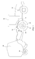
- FIG. 1 shows a possible arrangement of an agricultural work vehicle 50 with an only schematically indicated power-split transmission device 10, which is adapted to electrical power via a controller 26 and a power interface 54 in the form of an AEF connector an electrical load 60 in the form of an electric drive axle on a Attachment 56 to provide.
- an energy store 27 connected to the controller 26 may be provided to electrically store and dispense power.
- the energy store 27 may be, for example, a battery device.
- the electrical load 60 does not necessarily have to be an electric drive axle, nor does it have to be arranged on the attachment 56, but it can equally be arranged on the work vehicle 50.
- another standardized or non-standard interface can be used.
- the FIG. 2 shows a drive assembly of the agricultural working vehicle 50, in which a drive motor 52 in the form of an internal combustion engine, its drive power via a responsively switchable reversible Doppelplanetenradgetriebe 28 and transmits a transmission device 10 according to the invention to a traction drive 42.
- the traction drive 42 may regularly include a differential gear 48 and a rear drive axle 44 with wheels 58.
- the transmission device 10 comprises a summation gear 30 in the form of a planetary gear, an electric variator 20 for continuously setting a transmission ratio of the planetary gear 30 and a transmission with adjustable ratio 40 in the form of a group transmission with present five switching groups A, B, C, D and E.
- Die Structural unit consisting of the planetary gear 30 and the electric variator 20 is designated by the reference numeral 32 and forms the power-split electromechanical transmission unit of the transmission device 10.
- the planetary gear 30 can be immediately downstream of a if necessary engageable creeper 46.
- the electric variator 20 comprises a first electric machine 22, a second electric machine 24 and a controller 26 connected to the two electric machines 22, 24 and the AEF connector 54. Further power outputs, not shown, may be provided, for example an output for a PTO or an output for an on demand switchable front wheel drive.
- the drive of the planetary gear 30 is effected by the drive motor 52 via the ring gear 34 of the planetary gear 30 and the output in the direction of the transmission 40 via the planet carrier 38 of the planetary gear 30.
- the ring gear 34 to the drive shaft 64 of the drive motor 52nd be connected drivingly.
- the first electric machine 22 is drivingly connected to the sun gear 36 of the planetary gear 30 via a first spur gear stage 66 to continuously vary the gear ratio between the driven ring gear 34 and the driving gear carrier 38 of the planetary gear 30.
- the second electric machine 24 is drivingly connected to the drive shaft 64 of the drive motor 52 via a second spur gear stage 68.
- the transmission 40 is in the present embodiment as a dual-clutch transmission with a first countershaft 70, a second countershaft 72 and an output shaft 74 executed.
- the planet carrier 38 of the planetary gear 30 are a first held on the first countershaft 70 gear 76 and a second held on the second countershaft 72 gear 78 in a meshing engagement.
- the first gear 76 can be brought via a switching element 80 with the first countershaft 70 and the second gear 78 can be brought via a switching element 82 with the second countershaft 72 in a drive connection.
- a power flow to the output shaft 74 can be switched via unspecified gear pairings and switching elements, which in turn drives the traction drive 42.
- the first electric machine 22 in the one direction of rotation in the engine operation and in the opposite direction takes place via the controller 26, a torque adjustment of the two electric machines 22, 24 regardless of the speed of the two electric machines Direction to be operated in generator mode.
- the second electric machine 24 is operated in the generator mode and the electrical power generated thereby the first electric machine 22 provided for their motor operation.
- FIG. 3a Shown is the flow of power units, where a power unit is symbolized with an arrowhead.
- the drive motor 52 outputs four power units, of which three power units flow via the drive shaft 64 and the ring gear 34 in the planetary gear 30 and a power unit via the variator 20 and the sun gear 36 flows into the planetary gear 30, so that over the planet carrier 38 four power units in the direction of manual transmission 40 drain.
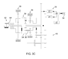
- a ratio is to be set for the planetary gear 30, for which a generator operation of the first electric machine 22 is required, thereby electrical power is generated, which can be made available to another electrical load.
- two scenarios are to be distinguished from each other:
- the controller 26 controls the second electric machine 24 in the engine mode and provides the electrical power generated by the first electric machine 22.
- This first scenario can be based on the FIG. 3b explained in qualitative terms become. Again, it is assumed that the drive motor 52 outputs four power units. However, since the first electric machine 22 is operated in the generator mode, via the sun gear 36 flows a power unit for driving into the first electric machine 22.
- This not externally discharged power unit flows back to the drive shaft 64 via the second electric machine 24 operated in the engine mode. so that five power units flow via the ring gear 34 into the planetary gear 30 together with the four output from the drive motor 52 power units. Since a power unit in turn flows to drive the first electric machine, four power units flow via the planet carrier 38 in the direction of the manual transmission 40. This power increase by one power unit within the planetary gear 30 is due to the reactive power circulating backwards across the variator 20.
- the electrical power generated by the first electric machine 22 may be provided to an external consumer, such as the electric drive axle of an implement.
- an external consumer such as the electric drive axle of an implement.
- the power unit generated by the first electric machine 22 is provided via the controller 26 and the AEF connector 54 to an external electrical load to cover a corresponding external line request.
- the second electric machine 24 is controlled by the controller 26 in the generator mode and the two power units generated by the two electric machines 22, 24 are provided via the AEF connector 54 an external electrical load. Accordingly, only two power units flow in the direction of the traction drive 42.
- the controller 26 can control the second electric machine in an idle state, so that corresponding to the four power units of the drive motor 52 only three power units in the direction of the traction drive 42 and a power unit flow over the AEF connector 54.
- the FIG. 4 shows the electrical power of the two electric machines 22, 24 of the variator 20, plotted against the travel speed of the work vehicle 50.
- the dash-dotted curve corresponds to the electrical power of the first electrical Machine 22 and the dashed curve of the electric power of the second electric machine 24.
- the zero-axis solid line corresponds to the output to an external load 60 electrical power, which is presently zero, since there is no external power requirement.
- the FIG. 4 shows the result of a calculation of the electrical power, which assumes a speed of the drive motor 52 of 1900 U / min and a full power utilization of the drive motor 52. Starting from a standstill accelerates the working vehicle 50 with switched power flow through the creep gear 31 and in the first gear range A of the transmission 40.
- the first electric machine 22 is operated in engine operation, such that the received electric power increases toward a positive value, and the second electric machine 24 operates in the generator mode so that the output electric power increases in the direction of a negative value.
- this shift range no reactive power circulates in the power split transmission unit 32.
- the power flow through the creeper gear 32 is bypassed and the work vehicle 50 continues to accelerate in the first gear range A of the transmission 40
- first the first electric machine 22 in the generator mode and the second electric machine 24 in the motor mode are operated so that reactive power is circulated in the gear unit 32.
- the FIG. 5 shows the result of a calculation of the electric powers using the transmission control method according to the invention. Again, it is assumed that a speed of the drive motor 52 of 1900 U / min and a full power utilization of the drive motor 52. Furthermore, it is assumed that a maximum output from external power of 90kW to cover an external power requirement. The magnitude 90kW of power to be supplied externally is merely a value assumed for the present calculation, which may vary in reality. Compared with the FIG. 4 are in the FIG. 5 the curves of the electrical power of the two electric machines 22, 24 basically the same.
- a power component as reactive power in the transmission unit 32 in which the FIG. 5 underlying transmission control method according to the invention, this power component provided via the controller 26 as external power an external electrical load 60 and at least predominantly not circulated in the transmission unit 32.
- this power component provided via the controller 26 as external power an external electrical load 60 and at least predominantly not circulated in the transmission unit 32.
- FIG. 5 are relative to the driving speed only relatively narrow areas to detect, in which a reactive power in the transmission unit 32 circulates. In these areas, the power regeneratively generated by the first electric machine 22 exceeds the power of 90kW output externally the second electric machine 24 is operated by a motor to pick up this excess power, which then circulates as reactive power in the transmission unit 32. Also in the FIG.
- the transmission control method makes it possible to generate electrical power with the existing transmission device in a relevant order of magnitude.
Landscapes
- Engineering & Computer Science (AREA)
- Mechanical Engineering (AREA)
- Transportation (AREA)
- Chemical & Material Sciences (AREA)
- Combustion & Propulsion (AREA)
- General Engineering & Computer Science (AREA)
- Power Engineering (AREA)
- Automation & Control Theory (AREA)
- Life Sciences & Earth Sciences (AREA)
- Soil Sciences (AREA)
- Environmental Sciences (AREA)
- Electric Propulsion And Braking For Vehicles (AREA)
- Hybrid Electric Vehicles (AREA)
- Structure Of Transmissions (AREA)
- Control Of Transmission Device (AREA)
Abstract
Description
- Die Erfindung betrifft ein Verfahren zur Ansteuerung einer leistungsverzweigten Getriebevorrichtung in einem landwirtschaftlichen Arbeitsfahrzeug, wobei die Getriebevorrichtung ein Summierungsgetriebe, einen elektrischen Variator zum stufenlosen Variieren einer Übersetzung des Summierungsgetriebe und ein Getriebe mit verstellbarer Übersetzung umfasst, um einen Antriebsmotor mit einem Fahrantrieb des Arbeitsfahrzeugs zu verbinden und wobei der elektrische Variator eine erste und eine zweite elektrische Maschine und eine Steuerung zur Ansteuerung der elektrischen Maschinen umfasst.
- Stufenlos leistungsverzweigte Getriebevorrichtungen sind in Baumaschinen und landwirtschaftlichen Arbeitsmaschinen, beispielsweise Traktoren, nach heutigem Stand der Technik insbesondere häufig im Premiumsegment anzutreffen und als hydraulischmechanisch leistungsverzweigte Getriebe ausgeführt. Der Leistungsfluss teilt sich hierbei in einen mechanischen Pfad, regelmäßig über einen oder mehrere Planetenradsätze geführt, und in einen hydrostatischen Pfad auf, in dem die Leistung über einen hydrostatischen Variator geführt wird, mit dem eine stufenlose Einstellung der Übersetzung vorgenommen werden kann. Am Markt erhältlich sind derartige Getriebevorrichtungen beispielsweise von Herstellern wie John Deere oder Fendt.
- Aus der
DE 197 49 74 C2 und derDE 10 2012 204 477 A1 sind stufenlos leistungsverzweigte Getriebevorrichtungen bekannt, bei denen der variable Pfad jeweils als elektrischer Variator ausgeführt ist. Bei derartigen elektro-mechanischen Getrieben wird sowohl mechanische als auch elektrische Leistung als Antriebsleistung genutzt. - Eine andere Entwicklungsrichtung bei Baumaschinen und landwirtschaftlichen Arbeitsfahrzeugen besteht in dem Aufbau eines zu dem bestehenden Bordnetz der Maschine zusätzlichen und mit einer höheren Nennspannung betriebenen zweiten Bordnetzes, mit dem elektrische Verbraucher, die eine derart höhere Nennspannung für ihren Betrieb benötigen, angetrieben werden können. Diese elektrischen Verbraucher können sowohl auf der Maschine an sich als auch auf einem Anbaugerät angeordnet sein. Herkömmlicherweise wird dieses zusätzliche zweite Bordnetz auf der Maschine durch ein eigenes dafür vorgesehenes Generatorsystem erzeugt. Hierbei entstehen allerdings zusätzliche Produktkosten und es reduziert sich der Gesamtwirkungsgrad infolge der zusätzlichen Bauteile.
- Ausgehend hiervon besteht die Aufgabe der vorliegenden Erfindung darin, ein Verfahren anzugeben, mit dem ein zweites Bordnetz auf dem Fahrzeug in integrierter Weise gespeist werden kann.
- Die Aufgabe wird gelöst durch ein Verfahren nach dem Oberbegriff des Anspruchs 1, bei dem erfindungsgemäß bei Erkennen einer externen Leistungsanforderung eines elektrischen Verbrauchers ein Übersetzungsbereich des Getriebe mit verstellbarer Übersetzung derart eingestellt wird, dass die erste elektrische Maschine generatorisch und die zweite elektrische Maschine derart betrieben wird, dass eine bezogen auf die externe Leistungsanforderung bestehende Leistungsunterdeckung oder Leistungsüberdeckung kompensiert wird.
- Unter externer Leistungsanforderung wird in diesem Kontext eine Leistungsanforderung verstanden, die außerhalb der Getriebevorrichtung entsteht. Somit kann die externe Leistungsanforderung beispielsweise von einem auf dem Arbeitsfahrzeug angeordneten elektrischen Verbraucher oder von einem auf einem Anbaugerät des Arbeitsfahrzeugs angeordneten elektrischen Verbraucher stammen.
- Unter einer Leistungsunterdeckung bzw. Leistungsüberdeckung wird in diesem Kontext eine Differenz zwischen der von den beiden elektrischen Maschinen oder nur einer der elektrischen Maschinen erzeugten elektrischen Leistung und der Höhe der externen Leistungsanforderung dahingehend verstanden, dass eine Unterdeckung vorliegt, wenn die externe Leistungsanforderung die erzeugte elektrische Leistung übersteigt, und dass eine Überdeckung vorliegt, wenn die erzeugte elektrische Leistung die externe Leistungsanforderung übersteigt.
- Es kann der Fall auftreten, dass die erste elektrische Maschine eine elektrische Leistung in einer bestimmten Höhe erzeugt, aber ein höherer externer Leistungsbedarf besteht. Um diese Differenz zumindest teilweise zu kompensieren wird die zweite elektrische Maschine ebenfalls generatorisch betrieben. Es kann andererseits der Fall auftreten, dass die erste elektrische Maschine eine elektrische Leistung in einer bestimmten Höhe erzeugt, aber ein niedrigerer externer Leistungsbedarf besteht. Um diese Differenz, die dann einen Leistungsüberschuss darstellt, zu kompensieren, wird die zweite elektrische Maschine motorisch betrieben, um diesen Leistungsüberschuss aufzunehmen.
- Erfindungsgemäß ist nun erkannt worden, dass eine im Variatorzweig entgegen der ursprünglichen Richtung fließende Leistung, auch Blindleistung genannt, zur Deckung einer externen Leistungsanforderung herangezogen werden kann. Hierzu kann gezielt ein solcher Übersetzungsbereich des Getriebes mit verstellbarer Übersetzung eingestellt werden, dass das Summierungsgetriebe eine Leistung in den Variatorzweig hinein abgibt. Diese in den Variatorzweig abgegebene Leistung wird nicht als Blindleistung in das Summierungsgetriebe zurückgeführt, da sie erfindungsgemäß über die erste elektrische Maschine und über die Steuerung als elektrische Leistung zur Deckung der externen Leistungsanforderung abgeführt wird.
- Bevorzugt wird das Summierungsgetriebe durch ein Planetenradgetriebe mit drei Antriebsschnittstellen gebildet, wobei je nach Richtung des Leistungsflusses die Antriebsschnittstellen als Eingang oder als Ausgang des Planetenradgetriebes wirken können. Es kann vorgesehen sein, dass der Antriebsmotor mit der ersten Antriebsschnittstelle des Planetenradgetriebes antriebsverbunden ist, um die Getriebevorrichtung mit Antriebsleistung zu versorgen, die wiederum über das mit der zweiten Antriebsschnittstelle des Planetenradgetriebes verbundene Getriebe mit verstellbarer Übersetzung an den Fahrantrieb weitergegeben werden kann. Weiterhin kann vorgesehen sein, dass die erste der beiden elektrischen Maschinen mit der dritten Antriebsschnittstelle des Planetenradgetriebes antriebsverbunden ist, um eine variable Übersetzung zwischen der ersten Antriebsschnittstelle und der zweiten Antriebsschnittstelle des Planetenradgetriebes darzustellen. Bevorzugt ist die zweite der beiden elektrischen Maschinen mit dem Antriebsmotor des Arbeitsfahrzeugs antriebsverbunden, wobei dies unter Zwischenschaltung einer Übersetzung in Form einer Stirnradstufe erfolgen kann.
- Während des Antriebs der Arbeitsmaschine durch den Antriebsmotor kann die erste elektrische Maschine im Generatorbetrieb und im Motorbetrieb betrieben werden. Der Generatorbetrieb erzeugt elektrische Leistung, die per Definition mit einem negativen Vorzeichen versehen ist, und der Motorbetrieb benötigt bzw. verbraucht elektrische Leistung. Der Leistungsbedarf im Motorbetrieb beziehungsweise die Leistungsabgabe im Generatorbetrieb der ersten elektrischen Maschine ist abhängig von der erforderlichen Zugkraft des Arbeitsfahrzeugs und der nötigen Drehzahl der ersten elektrischen Maschine, um das einzustellende Übersetzungsverhältnis des Planetenradgetriebes zu erreichen.
- Im Fall einer externen Leistungsanforderung kann ein Übersetzungsbereich des Getriebes mit verstellbarer Übersetzung gewählt werden, so dass die erste elektrische Maschine im Generatorbetrieb betrieben wird. Die von der ersten elektrischen Maschine im Generatorbetrieb abgegebene elektrische Leistung kann über die Steuerung einem externen elektrischen Verbraucher zur Verfügung gestellt, um einen bestehenden externen Leistungsbedarf zu decken. Insgesamt steigt durch das erfindungsgemäße Getriebesteuerverfahren der an der Ausgangswelle und der Steuerung der Getriebevorrichtung erzielte Gesamtwirkungsgrad, da die elektrische Leistung der ersten Maschine zur Erfüllung von Zugkrafterfordernissen ohnehin erzeugt werden muss. Der Vorteil besteht nun darin, dass diese elektrische Leistung nicht als Blindleistung über den Variatorzweig wieder in das Planetenradgetriebe eingespeist wird, sondern über die Steuerung einem externen elektrischen Verbraucher zur Verfügung gestellt wird.
- Bevorzugt wird eine Übersetzung des Getriebes unter Berücksichtigung eines Fahrwiderstandes, der externen Leistungsanforderung und eines Fahrgeschwindigkeitswunsches eingestellt. Hierdurch wird sichergestellt, dass ein Übersetzungsbereich des Getriebes mit verstellbarer Übersetzung nur dann angesteuert wird bzw. nur dann ein anderer als der vorliegende Übersetzungsbereich angesteuert wird, wenn der momentan herrschende Fahrwiderstand und die Fahrgeschwindigkeit dies erlauben.
- Bevorzugt ist ein mit der Steuerung verbundener Energiespeicher vorgesehen, um eine bezogen auf die externe Leistungsanforderung bestehende Leistungsüberdeckung oder Leistungsunterdeckung zu kompensieren. Hierdurch ist gewährleistet, dass im Falle einer Leistungsüberdeckung nochmals weniger Leistung als Blindleistung zirkuliert und im Falle einer Leistungsunterdeckung kann aus dem Energiespeicher Leistung zugesteuert werden.
- Bevorzugt erfolgt über die Steuerung eine Drehmomentverstellung der elektrischen Maschinen unabhängig von der Drehzahl der elektrischen Maschinen, um Energie in jede der elektrischen Maschinen oder einen Energiespeicher zu speisen und jede der beiden elektrischen Maschinen generatorisch zu betreiben.
- Die Erfindung wird im Folgenden anhand der Figuren beschrieben. Hierin zeigen
- Figur 1
- ein landwirtschaftliches Arbeitsfahrzeug mit einem Anbaugerät;
- Figur 2
- ein Getriebeschema zur Ausführung des erfindungsgemäßen Getriebesteuerverfahrens;
- Figuren 3a - 3c
- verschiedene Leistungsflüsse in einem Getriebeschema;
- Figur 4
- elektrische Leistungsverläufe über der Fahrzeuggeschwindigkeit ohne erfindungsgemäße Getriebesteuerung und
- Figur 5
- elektrische Leistungsverläufe über der Fahrzeuggeschwindigkeit mit erfindungsgemäßer Getriebesteuerung.
- Die
Figur 1 zeigt eine mögliche Anordnung eines landwirtschaftlichen Arbeitsfahrzeugs 50 mit einer nur schematisch angedeuteten leistungsverzweigten Getriebevorrichtung 10, die dazu hergerichtet ist, eine elektrische Leistung über eine Steuerung 26 und eine Leistungsschnittstelle 54 in Form eines AEF-Konnektors einem elektrischen Verbraucher 60 in Form einer elektrischen Antriebsachse auf einem Anbaugerät 56 bereitzustellen. Außerdem kann ein mit der Steuerung 26 verbundener Energiespeicher 27 vorgesehen sein, um elektrisch Leistung zu speichern und abzugeben. Bei dem Energiespeicher 27 kann es sich beispielsweise um eine Batterievorrichtung handeln. Bei dieser Anordnung handelt es sich nur um ein mögliches Beispiel. So muss der elektrische Verbraucher 60 weder zwingend eine elektrische Antriebsachse sein, noch muss er auf dem Anbaugerät 56 angeordnet sein, sondern kann gleichermaßen auf dem Arbeitsfahrzeug 50 angeordnet sein. Auch kann anstatt eines AEF-Konnektors eine andere genormte oder nicht genormte Schnittstelle zum Einsatz kommen. - Die
Figur 2 zeigt eine Antriebsanordnung des landwirtschaftlichen Arbeitsfahrzeugs 50, bei der ein Antriebsmotor 52 in Form einer Verbrennungskraftmaschine seine Antriebsleistung über ein bedarfsweise zuschaltbares reversierbares Doppelplanetenradgetriebe 28 und eine erfindungsgemäße Getriebevorrichtung 10 auf einen Fahrantrieb 42 überträgt. Der Fahrantrieb 42 kann regelmäßig ein Differentialgetriebe 48 und eine hintere Antriebsachse 44 mit Rädern 58 umfassen. Die Getriebevorrichtung 10 umfasst ein Summierungsgetriebe 30 in Form eines Planetenradgetriebes, einen elektrischen Variator 20 zum stufenlosen Einstellen eines Übersetzungsverhältnisses des Planetenradgetriebes 30 und ein Getriebe mit verstellbarer Übersetzung 40 in Form eines Gruppenschaltgetriebes mit vorliegend fünf Schaltgruppen A, B, C, D und E. Die bauliche Einheit bestehend aus dem Planetenradgetriebe 30 und dem elektrischen Variator 20 ist mit dem Bezugszeichen 32 gekennzeichnet und bildet die leistungsverzweigte elektromechanische Getriebeeinheit der Getriebevorrichtung 10. Dem Planetenradgetriebe 30 kann unmittelbar ein bedarfsweise zuschaltbares Kriechganggetriebe 46 nachgeordnet sein. Der elektrische Variator 20 umfasst eine erste elektrische Maschine 22, eine zweite elektrische Maschine 24 und eine mit den beiden elektrischen Maschinen 22, 24 und dem AEF-Konnektor 54 verbundene Steuerung 26. Es können weitere aber nicht dargestellte Abtriebe vorgesehen sein, beispielsweise ein Abtrieb für einen Zapfwellenantrieb oder ein Abtrieb für einen bedarfsweise zuschaltbaren Vorderradantrieb. - Der Antrieb des Planetenradgetriebes 30 erfolgt durch den Antriebsmotor 52 über das Hohlrad 34 des Planetenradgetriebes 30 und der Abtrieb in Richtung des Getriebes 40 erfolgt über den Planetenradträger 38 des Planetenradgetriebes 30. Hierzu kann über ein Schaltelement 62 das Hohlrad 34 mit der Antriebswelle 64 des Antriebsmotors 52 antriebsmäßig verbunden werden. Die erste elektrische Maschine 22 ist über eine erste Stirnradstufe 66 antriebsmäßig mit dem Sonnenrad 36 des Planetenradgetriebes 30 verbunden, um stufenlos das Übersetzungsverhältnis zwischen dem angetriebenen Hohlrad 34 und dem treibenden Planetenradträger 38 des Planetenradgetriebes 30 zu variieren. Die zweite elektrische Maschine 24 ist über eine zweite Stirnradstufe 68 antriebsmäßig mit der Antriebswelle 64 des Antriebsmotors 52 verbunden.
- Das Getriebe 40 ist bei dem vorliegenden Ausführungsbeispiel als Doppelkupplungsgetriebe mit einer ersten Vorgelegewelle 70, einer zweiten Vorgelegewelle 72 und einer Abtriebswelle 74 ausgeführt. Mit dem Planetenradträger 38 des Planetenradgetriebes 30 stehen ein erstes auf der ersten Vorgelegewelle 70 gehaltenes Zahnrad 76 und ein zweites auf der zweiten Vorgelegewelle 72 gehaltenes Zahnrad 78 in einem Verzahnungseingriff. Das erste Zahnrad 76 kann über ein Schaltelement 80 mit der ersten Vorgelegewelle 70 und das zweite Zahnrad 78 kann über ein Schaltelement 82 mit der zweiten Vorgelegewelle 72 in eine Antriebsverbindung gebracht werden. Ausgehend von den Vorgelegewellen 70, 72 kann über nicht näher zu beschreibende Zahnradpaarungen und Schaltelemente ein Kraftfluss zu der Abtriebswelle 74 geschaltet werden, die ihrerseits den Fahrantrieb 42 antreibt.
- Über die Steuerung 26 erfolgt eine Drehmomentverstellung der beiden elektrischen Maschinen 22, 24 unabhängig von der Drehzahl der beiden elektrischen Maschinen 22, 24. Abhängig von der einzustellenden Übersetzung des Planetenradgetriebes 30 kann die erste elektrische Maschine 22 in der einen Drehrichtung im Motorbetrieb und in der entgegengesetzten Richtung im Generatorbetrieb betrieben werden. Wenn für das Planetenradgetriebe 30 eine Übersetzung einzustellen ist, für die ein Motorbetrieb der ersten elektrischen Maschine 22 erforderlich ist, so wird die zweite elektrische Maschine 24 im Generatorbetrieb betrieben und die hierdurch erzeugte elektrische Leistung der ersten elektrischen Maschine 22 für deren Motorbetrieb zur Verfügung gestellt. Dieser Fall der Ansteuerung kann anhand der
Figur 3a in qualitativer Hinsicht erläutert werden. Gezeigt ist der Fluss von Leistungseinheiten, wobei eine Leistungseinheit mit einer Pfeilspitze symbolisiert wird. Es wird angenommen, dass der Antriebsmotor 52 vier Leistungseinheiten abgibt, von denen drei Leistungseinheiten über die Antriebswelle 64 und das Hohlrad 34 in das Planetenradgetriebe 30 fließen und eine Leistungseinheit über den Variator 20 und über das Sonnenrad 36 in das Planetenradgetriebe 30 fließt, so dass über den Planetenradträger 38 vier Leistungseinheiten in Richtung Schaltgetriebe 40 abfließen. - Wenn für das Planetenradgetriebe 30 eine Übersetzung einzustellen ist, für die ein Generatorbetrieb der ersten elektrischen Maschine 22 erforderlich ist, so wird hierdurch elektrische Leistung erzeugt, die einem anderen elektrischen Verbraucher zur Verfügung gestellt werden kann. Hierbei sind zwei Szenarien voneinander zu unterscheiden: Bei dem ersten Szenario besteht keine externe Leistungsanforderung, so dass die Steuerung 26 die zweite elektrische Maschine 24 im Motorbetrieb ansteuert und ihr die von der ersten elektrischen Maschine 22 erzeugte elektrische Leistung zur Verfügung stellt. Dieses erste Szenario kann anhand der
Figur 3b in qualitativer Hinsicht erläutert werden. Wieder wird angenommen, dass der Antriebsmotor 52 vier Leistungseinheiten abgibt. Da die erste elektrische Maschine 22 jedoch im Generatorbetrieb betrieben wird, fließt über das Sonnenrad 36 eine Leistungseinheit zum Antrieb in die erste elektrische Maschine 22. Diese nicht nach Extern abgeführte Leistungseinheit fließt über die im Motorbetrieb betriebene zweite elektrische Maschine 24 zurück auf die Antriebswelle 64, so dass zusammen mit den vier von dem Antriebsmotor 52 abgegebenen Leistungseinheiten fünf Leistungseinheiten über das Hohlrad 34 in das Planetenradgetriebe 30 fließen. Da hiervon eine Leistungseinheit wiederum zum Antrieb der ersten elektrischen Maschine abfließt, fließen vier Leistungseinheiten über den Planetenradträger 38 in Richtung Schaltgetriebe 40 ab. Diese Leistungsüberhöhung um eine Leistungseinheit innerhalb des Planetenradgetriebes 30 ergibt sich infolge der über den Variator 20 rückwärts zirkulierenden Blindleistung. - Bei dem zweiten Szenario besteht eine externe Leistungsanforderung, so dass die von der ersten elektrischen Maschine 22 erzeugte elektrische Leistung einem externen Verbraucher, beispielsweise der elektrischen Antriebsachse eines Anbaugeräts, zur Verfügung gestellt werden kann. Dieses zweite Szenario kann anhand der
Figur 3c in qualitativer Hinsicht erläutert werden. In derFigur 3c wird die von der ersten elektrischen Maschine 22 erzeugte Leistungseinheit über die Steuerung 26 und den AEF-Konnektor 54 einem externen elektrischen Verbraucher zur Verfügung gestellt, um eine entsprechende externe Leitungsanforderung zu decken. Zusätzlich wird die zweite elektrische Maschine 24 von der Steuerung 26 im Generatorbetrieb angesteuert und die zwei durch die beiden elektrischen Maschinen 22, 24 erzeugten Leistungseinheiten werden über den AEF-Konnektor 54 einem externen elektrischen Verbraucher zur Verfügung gestellt. Entsprechend fließen nur zwei Leistungseinheiten in Richtung des Fahrantriebs 42. Lediglich in einem hier nicht dargestellten Sonderfall kann die Steuerung 26 die zweite elektrische Maschine in einem Leerlaufzustand ansteuern, so dass entsprechend von den vier Leistungseinheiten des Antriebsmotors 52 nur drei Leistungseinheiten in Richtung des Fahrantriebs 42 und eine Leistungseinheit über den AEF-Konnektor 54 fließen. - Die
Figur 4 zeigt die elektrischen Leistungen der beiden elektrischen Maschinen 22, 24 des Variators 20, aufgetragen über der Fahrgeschwindigkeit des Arbeitsfahrzeugs 50. Die strichpunktierte Kurve entspricht der elektrischen Leistung der ersten elektrischen Maschine 22 und die gestrichelte Kurve der elektrischen Leistung der zweiten elektrischen Maschine 24. Die auf der Null-Achse liegende durchgezogene Linie entspricht der an einen externen Verbraucher 60 abgegebenen elektrischen Leistung, die vorliegend Null ist, da keine externe Leistungsanforderung vorliegt. DieFigur 4 zeigt das Ergebnis einer Berechnung der elektrischen Leistungen, die von einer Drehzahl des Antriebsmotors 52 von 1900 U/min und einer vollständigen Leistungsauslastung des Antriebsmotors 52 ausgeht. Zu erkennen sind gegenläufige Verläufe der Leistungen der beiden elektrischen Maschinen 22, 24. Ausgehend von einem Stillstand beschleunigt das Arbeitsfahrzeug 50 mit geschaltetem Kraftfluss über das Kriechganggetriebe 31 und im ersten Übersetzungsbereich A des Getriebes 40. Zunächst wird die erste elektrische Maschine 22 im Motorbetrieb betrieben, so dass die aufgenommene elektrische Leistung in Richtung eines positiven Wertes ansteigt, und die zweite elektrische Maschine 24 im Generatorbetrieb betrieben, so dass die abgegebene elektrische Leistung in Richtung eines negativen Wertes ansteigt. In diesem Schaltbereich zirkuliert keine Blindleistung in der leistungsverzweigten Getriebeeinheit 32. Wenn die beiden elektrischen Maschinen 22, 24 ihren betragsmäßig maximalen Leistungswert erreichen, wird der Kraftfluss über das Kriechganggetriebe 32 umgangen und das Arbeitsfahrzeug 50 beschleunigt weiter in dem ersten Übersetzungsbereich A des Getriebes 40. In diesem Schaltbereich werden zunächst die erste elektrische Maschine 22 im Generatorbetrieb und die zweite elektrische Maschine 24 im Motorbetrieb betrieben, so dass Blindleistung in der Getriebeeinheit 32 zirkuliert. Dieser Blindleistungsfluss hält an, bis ein Wechsel der Betriebsmodi der beiden elektrischen Maschinen 22, 24 stattfindet, so dass die erste elektrische Maschine 22 im Motorbetrieb und die zweite elektrische Maschine 24 im Generatorbetrieb betrieben werden und keine Blindleistung zirkuliert. Wenn die beiden elektrischen Maschinen 22, 24 wieder ihren betragsmäßig maximalen Leistungswert erreichen, wird in den zweiten Übersetzungsbereich B des Getriebes 40 geschaltet und das Arbeitsfahrzeug 50 beschleunigt weiter. Sowohl für diesen als auch die weiteren Übersetzungsbereich C, D, E des Schaltgetriebes 40 entsprechen die Verläufe der elektrischen Leistungen der beiden elektrischen Maschinen 22, 24 wie soeben für die Übersetzungsbereich A und B beschrieben, das heißt nach dem Schalten in den Übersetzungsbereich zirkuliert zunächst Blindleistung in der Getriebeeinheit 32, bis bei weiterer Beschleunigung die erste elektrische Maschine 22 im Motorbetrieb und die zweite elektrische Maschine 24 im Generatorbetrieb betrieben werden. - Die
Figur 5 zeigt das Ergebnis einer Berechnung der elektrischen Leistungen unter Anwendung des erfindungsgemäßen Getriebeansteuerverfahrens. Auch hier wird ausgegangen von einer Drehzahl des Antriebsmotors 52 von 1900 U/min und einer vollständigen Leistungsauslastung des Antriebsmotors 52. Ferner wird von einer maximalen nach Extern abzugebenden Leistung von 90kW ausgegangen, um einen externen Leistungsbedarf zu decken. Bei der Größenordnung 90kW nach Extern abzugebender Leistung handelt es sich lediglich um einen für die vorliegende Berechnung angenommenen Wert, der in der Realität variieren kann. Verglichen mit derFigur 4 sind in derFigur 5 die Verläufe der elektrischen Leistungen der beiden elektrischen Maschinen 22, 24 grundsätzlich gleich. Das heißt nach einem Wechsel der Übersetzungsbereiche des Schaltgetriebes 40 Wechseln die beiden elektrischen Maschinen 22, 24 ihre Betriebsmodi, was allerdings in der Realität infolge nicht infinitesimal kurzer Schaltzeiten nicht derart zügig erfolgen kann, und während des Durchlaufens der Übersetzungsbereiche verlaufen die elektrischen Leistungen der beiden Maschinen 22, 24 mit entgegengesetzter Steigung zu einander und kreuzen sich innerhalb eines Übersetzungsbereichs. Im Unterschied zuFigur 4 sind bei den Verläufen derFigur 5 die Schaltpunkte zwischen den Übersetzungsbereichen des Schaltgetriebes 40 erfindungsgemäß derart gewählt worden, dass sie, bezogen auf die Fahrgeschwindigkeit, früher vollzogen werden und die Bereiche, in denen beide elektrische Maschinen 22, 24 im Generatorbetrieb betrieben werden, vergrößert beziehungsweise bezogen auf Fahrgeschwindigkeitsbereiche verbreitert werden. Verglichen mit derFigur 4 , in denen in bestimmten Bereichen ein Leistungsanteil als Blindleistung in der Getriebeeinheit 32 zirkuliert, wird bei dem derFigur 5 zugrundeliegenden Getriebeansteuerverfahren gemäß der Erfindung dieser Leistungsanteil über die Steuerung 26 als externe Leistung einem externen elektrischen Verbraucher 60 zur Verfügung gestellt und zumindest überwiegend nicht in der Getriebeeinheit 32 zirkuliert. In derFigur 5 sind bezogen auf die Fahrgeschwindigkeit lediglich verhältnismäßig schmale Bereiche zu erkennen, in denen eine Blindleistung in der Getriebeeinheit 32 zirkuliert. In diesen Bereichen übersteigt die durch die erste elektrische Maschine 22 generatorisch erzeugte Leistung die nach Extern abgegebene Leistung von 90kW, so dass die zweite elektrische Maschine 24 motorisch betrieben wird, um diese überschüssige Leistung aufzunehmen, welche dann als Blindleistung in der Getriebeeinheit 32 zirkuliert. Auch sind in derFigur 5 Bereiche zu erkennen, in denen die erste elektrische Maschine 22 motorisch und die zweite elektrische Maschine 24 generatorisch betrieben werden, wobei allerdings die von der zweiten elektrischen Maschine 24 erzeugte elektrische Leistung die von der ersten elektrischen Maschine 22 aufgenommene Leistung übersteigt, so dass die den Leistungsbedarfs der ersten elektrischen Maschine 22 übersteigende Leistung als externe Leistung zur Verfügung gestellt werden kann. - Zusammenfassend ergibt sich bei einer erfindungsgemäßen Getriebesteuerung der beispielmäßig beschriebenen Getriebevorrichtung die Möglichkeit beide elektrische Maschinen im Generatorbetrieb zu betrieben, wodurch der Gesamtwirkungsgrad der Getriebevorrichtung steigt. Zudem ergibt sich durch das Getriebesteuerverfahren die Möglichkeit mit der bestehenden Getriebevorrichtung in einer relevanten Größenordnung elektrische Leistung zu generieren.
-
- 10
- Getriebevorrichtung
- 20
- Variator
- 22
- elektrische Maschine
- 24
- elektrische Maschine
- 26
- Steuerung
- 27
- Energiespeicher
- 28
- Doppelplanetenradgetriebe
- 30
- Summierungsgetriebe
- 32
- elektro-mechanische Getriebeeinheit
- 34
- Hohlrad
- 36
- Sonnenrad
- 38
- Planetenradträger
- 40
- Getriebe
- 42
- Fahrantrieb
- 44
- Antriebsachse
- 46
- Kriechganggetriebe
- 48
- Differentialgetriebe
- 50
- Arbeitsfahrzeug
- 52
- Antriebsmotor
- 54
- Leistungsschnittstelle
- 56
- Anbaugerät
- 58
- Räder
- 60
- elektrischer Verbraucher
- 62
- Schaltelement
- 64
- Antriebswelle
- 66
- Stirnradstufe
- 68
- Stirnradstufe
- 70
- Vorgelegewelle
- 72
- Vorgelegewelle
- 74
- Abtriebswelle
- 76
- erstes Zahnrad
- 78
- zweites Zahnrad
Claims (4)
- Verfahren zur Ansteuerung einer leistungsverzweigten Getriebevorrichtung (10) in einem landwirtschaftlichen Arbeitsfahrzeug (50),
wobei die Getriebevorrichtung (10) ein Summierungsgetriebe (30), einen elektrischen Variator (20) zum stufenlosen Variieren einer Übersetzung des Summierungsgetriebe (30) und ein Getriebe mit verstellbarer Übersetzung (40) umfasst, um einen Antriebsmotor (52) mit einem Fahrantrieb (42) des Arbeitsfahrzeugs (50) zu verbinden und
wobei der elektrische Variator (20) eine erste und eine zweite elektrische Maschine (22, 24) und eine Steuerung (26) der elektrischen Maschinen (22, 24) umfasst,
bei dem bei Erkennen einer externen Leistungsanforderung eines elektrischen Verbrauchers (60) ein Übersetzungsbereich des Getriebe mit verstellbarer Übersetzung (40) derart eingestellt wird, dass die erste elektrische Maschine (22) generatorisch und die zweite elektrische Maschine (24) derart betrieben wird, dass eine bezogen auf die externe Leistungsanforderung bestehende Leistungsunterdeckung oder Leistungsüberdeckung kompensiert wird. - Verfahren nach Anspruch 1, dadurch gekennzeichnet, dass eine Übersetzung des Getriebes (40) unter Berücksichtigung eines Fahrwiderstandes, der externen Leistungsanforderung und eines Fahrgeschwindigkeitswunsches eingestellt wird.
- Verfahren nach Anspruch 1 oder 2, dadurch gekennzeichnet, dass ein mit der Steuerung (26) verbundener Energiespeicher (27) vorgesehen ist, um eine bezogen auf die externe Leistungsanforderung bestehende Leistungsüberdeckung oder Leistungsunterdeckung zu kompensieren.
- Verfahren nach einem der Ansprüche 1 bis 3, dadurch gekennzeichnet, dass über die Steuerung (26) eine Drehmomentverstellung der elektrischen Maschinen (22, 24) unabhängig von der Drehzahl der elektrischen Maschinen (22, 24) erfolgen kann, um Energie in jede der elektrischen Maschinen (22, 24) oder einen Energiespeicher (27) zu speisen und jede der beiden elektrische Maschinen (22, 24) generatorisch zu betreiben.
Applications Claiming Priority (2)
| Application Number | Priority Date | Filing Date | Title |
|---|---|---|---|
| DE102014219438 | 2014-09-25 | ||
| DE102015208160.5A DE102015208160B4 (de) | 2014-09-25 | 2015-05-04 | Getriebesteuerverfahren |
Publications (2)
| Publication Number | Publication Date |
|---|---|
| EP3006245A1 true EP3006245A1 (de) | 2016-04-13 |
| EP3006245B1 EP3006245B1 (de) | 2020-04-22 |
Family
ID=54151164
Family Applications (2)
| Application Number | Title | Priority Date | Filing Date |
|---|---|---|---|
| EP15185916.2A Active EP3006245B1 (de) | 2014-09-25 | 2015-09-18 | Getriebesteuerverfahren |
| EP15185924.6A Active EP3006776B1 (de) | 2014-09-25 | 2015-09-18 | Getriebesteuerverfahren |
Family Applications After (1)
| Application Number | Title | Priority Date | Filing Date |
|---|---|---|---|
| EP15185924.6A Active EP3006776B1 (de) | 2014-09-25 | 2015-09-18 | Getriebesteuerverfahren |
Country Status (3)
| Country | Link |
|---|---|
| US (2) | US9562592B2 (de) |
| EP (2) | EP3006245B1 (de) |
| DE (1) | DE102015208160B4 (de) |
Cited By (1)
| Publication number | Priority date | Publication date | Assignee | Title |
|---|---|---|---|---|
| EP3567167A3 (de) * | 2018-05-08 | 2019-11-27 | Robert Bosch GmbH | Hydraulische steueranordnung für eine anordnung mobiler arbeitsmaschinen und anordnung mobiler arbeitsmaschinen |
Families Citing this family (62)
| Publication number | Priority date | Publication date | Assignee | Title |
|---|---|---|---|---|
| KR101725882B1 (ko) * | 2013-03-27 | 2017-04-11 | 스카니아 씨브이 악티에볼라그 | 기어박스를 구비하는 하이브리드 파워트레인 및 그러한 하이브리드 구동트레인을 제어하는 방법 |
| SE1350394A1 (sv) | 2013-03-27 | 2014-09-28 | Scania Cv Ab | Växellåda, fordon med en sådan växellåda, förfarande för attstyra en sådan växellåda, datorprogram för att styra en sådan växellåda, samt en datorprogramprodukt innefattande programkod |
| SE1350393A1 (sv) | 2013-03-27 | 2014-09-28 | Scania Cv Ab | Växellåda, fordon med en sådan växellåda, förfarande för attstyra en sådan växellåda, datorprogram för att styra en sådan växellåda, samt en datorprogramprodukt innefattande programkod |
| US10670124B2 (en) | 2013-12-31 | 2020-06-02 | Deere & Company | Multi-mode infinitely variable transmission |
| US10655710B2 (en) | 2013-12-31 | 2020-05-19 | Deere & Company | Multi-mode infinitely variable transmission that provides seamless shifting |
| SE537896C2 (sv) | 2014-03-20 | 2015-11-17 | Scania Cv Ab | Förfarande för att starta en förbränningsmotor i en hybriddrivlina, fordon med en sådan hybriddrivlina, datorprogram föratt starta en förbränningsmotor, samt en datorprogramprodukt innefattande programkod |
| SE539002C2 (sv) | 2014-03-20 | 2017-03-14 | Scania Cv Ab | Förfarande för att styra en hybriddrivlina, fordon med en sådan hybriddrivlina, datorprogram för att styra en sådan hybriddrivlina, samt en datorprogramprodukt innefattande programkod |
| SE540692C2 (sv) | 2014-03-20 | 2018-10-09 | Scania Cv Ab | Förfarande för att styra en hybriddrivlina, fordon med en sådan hybriddrivlina, datorprogram för att styra en sådan hybriddrivlina, samt en datorprogramprodukt innefattande programkod |
| SE540693C2 (sv) | 2014-03-20 | 2018-10-09 | Scania Cv Ab | Förfarande för att styra en hybriddrivlina, fordon med en sådan hybriddrivlina, datorprogram för att styra en sådan hybriddrivlina, samt en datorprogramprodukt innefattande programkod |
| SE538735C2 (sv) | 2014-03-20 | 2016-11-08 | Scania Cv Ab | Förfarande för att styra en hybriddrivlina för att optimera bränsleförbrukningen |
| SE538737C2 (sv) * | 2014-03-20 | 2016-11-08 | Scania Cv Ab | Förfarande för att styra en hybriddrivlina, fordon med en sådan hybriddrivlina, datorprogram för att styra en hybriddrivlina, samt en datorprogramprodukt innefattande programkod |
| SE538736C2 (sv) | 2014-03-20 | 2016-11-08 | Scania Cv Ab | Förfarande för att styra en hybriddrivlina för att optimera det drivande momentet från en hos hybriddrivlinan anordnad förbränningsmotor |
| SE537897C2 (sv) | 2014-03-20 | 2015-11-17 | Scania Cv Ab | Förfarande för ivägkörning av ett fordon med en hybriddrivlina, fordon med en sådan hybriddrivlina, datorprogram för attstyra ivägkörning av ett fordon, samt en datorprogramprodukt innefattande programkod |
| SE539032C2 (sv) | 2014-03-20 | 2017-03-21 | Scania Cv Ab | Förfarande för att styra en hybriddrivlina, fordon med en sådan hybriddrivlina, datorprogram för att styra en sådan hybriddrivlina, samt en datorprogramprodukt innefattande programkod |
| SE539660C2 (sv) | 2014-03-20 | 2017-10-24 | Scania Cv Ab | Förfarande för att starta en förbränningsmotor i en hybriddrivlina, fordon med en sådan hybriddrivlina, datorprogram föratt starta en förbränningsmotor, samt en datorprogramproduk t innefattande programkod |
| SE539030C2 (sv) | 2014-03-20 | 2017-03-21 | Scania Cv Ab | Förfarande för att styra en hybriddrivlina, fordon med en sådan hybriddrivlina, datorprogram för att styra en sådan hybriddrivlina, samt en datorprogramprodukt innefattande programkod |
| SE539661C2 (sv) | 2014-03-20 | 2017-10-24 | Scania Cv Ab | Förfarande för att starta en förbränningsmotor hos en hybriddrivlina, fordon med en sådan förbränningsmotor, datorprogram för att starta en sådan förbränningsmotor, samt en datorprogramprodukt innefattande programkod |
| SE539028C2 (sv) | 2014-03-20 | 2017-03-21 | Scania Cv Ab | Förfarande för ivägkörning av ett fordon med en hybriddrivlina, fordon med en sådan hybriddrivlina, datorprogram för attstyra ivägkörning av ett fordon, samt en datorprogramproduk t innefattande programkod |
| SE539662C2 (sv) | 2014-03-20 | 2017-10-24 | Scania Cv Ab | Förfarande för att starta en förbränningsmotor i en hybriddrivlina, fordon med en sådan hybriddrivlina, datorprogram föratt starta en förbränningsmotor, samt en datorprogramproduk t innefattande programkod |
| SE538187C2 (sv) | 2014-03-20 | 2016-03-29 | Scania Cv Ab | Förfarande för att styra en hybriddrivlina, fordon med en sådan hybriddrivlina, datorprogram för att styra en sådan hybriddrivlina, samt en datorprogramprodukt innefattande programkod |
| US10738868B2 (en) | 2014-04-09 | 2020-08-11 | Deere & Company | Multi-mode powertrains |
| US10647193B2 (en) | 2014-04-09 | 2020-05-12 | Deere & Company | Multi-mode power trains |
| EP3305612B1 (de) * | 2015-06-01 | 2020-07-22 | Nissan Motor Co., Ltd. | Startsteuerungsvorrichtung für ein hybridfahrzeug |
| DE102016204727A1 (de) * | 2016-03-22 | 2017-09-28 | Zf Friedrichshafen Ag | Stufenlos leistungsverzweigtes Getriebe mit mindestens einem Fahrbereich |
| DE102016218159A1 (de) | 2016-09-21 | 2018-03-22 | Zf Friedrichshafen Ag | Antriebsanordnung mit einer leistungsverzweigten Getriebevorrichtung |
| US10278332B2 (en) | 2016-10-05 | 2019-05-07 | Deere & Company | Chopper timing adjustment |
| US10800247B2 (en) * | 2017-02-21 | 2020-10-13 | Ford Global Technologies, Llc | Hybrid vehicle powertrain with manual transmission |
| US10619711B2 (en) | 2017-04-12 | 2020-04-14 | Deere & Company | Infinitely variable transmission with power reverser |
| DE102017219799A1 (de) * | 2017-11-08 | 2019-05-09 | Zf Friedrichshafen Ag | Teilelektrifizierte Arbeitsmaschine |
| DE102018202854B4 (de) * | 2018-02-26 | 2020-01-02 | Audi Ag | Verfahren zum Betrieb eines Bordnetzes eines Hybridkraftfahrzeugs und Hybridkraftfahrzeug |
| US11052747B2 (en) | 2018-05-04 | 2021-07-06 | Deere & Company | Multi-mode powertrains |
| US11091018B2 (en) | 2018-05-11 | 2021-08-17 | Deere & Company | Powertrain with variable vertical drop distance |
| DE102018215684A1 (de) * | 2018-09-14 | 2020-03-19 | Deere & Company | Leistungsverzweigte Getriebestruktur |
| US10975959B2 (en) | 2019-04-01 | 2021-04-13 | Deere & Company | Transmission clutch braking control system |
| US11137052B2 (en) | 2019-08-29 | 2021-10-05 | Deere & Company | Transmission assembly with integrated CVP |
| DE102019214355A1 (de) * | 2019-09-20 | 2021-03-25 | Zf Friedrichshafen Ag | Antriebssystem eines land- oder bauwirtschaftlich nutzbaren Fahrzeugs und Verfahren zu dessen Betrieb gemeinsam mit einem zumindest einen elektrischen Verbraucher aufweisenden Anbaugerät |
| DE102019214354A1 (de) * | 2019-09-20 | 2021-03-25 | Zf Friedrichshafen Ag | Verfahren zum Betreiben eines Antriebssystems, Antriebssystem und Nutzfahrzeug |
| US11700792B2 (en) | 2019-10-25 | 2023-07-18 | Deere & Company | Torque smoothing apparatuses for large square balers |
| US11607956B2 (en) | 2019-10-31 | 2023-03-21 | Deere & Company | Trailing vehicle traction control system with a disconnect device |
| US11872885B2 (en) | 2019-10-31 | 2024-01-16 | Deere & Company | Trailing vehicle traction control system with force increase control |
| US11351983B2 (en) | 2019-10-31 | 2022-06-07 | Deere & Company | Power control system with transmission transient boost function |
| SE543783C2 (en) * | 2019-11-13 | 2021-07-20 | Scania Cv Ab | A method for driving at least one power consumer connected to a powertrain |
| US11846085B2 (en) | 2020-02-17 | 2023-12-19 | Deere & Company | Energy management system for a hybrid vehicle with an electrically powered hydraulic system |
| US12180672B2 (en) | 2020-03-02 | 2024-12-31 | Doosan Bobcat North America, Inc. | Electrically powered power machine |
| US11396231B2 (en) | 2020-07-20 | 2022-07-26 | Deere & Company | Drivetrain overload protection for work vehicles using power boost |
| US11325459B2 (en) | 2020-10-09 | 2022-05-10 | Deere & Company | Low profile transmission assembly with integrated CVP |
| CN112406507B (zh) * | 2020-10-29 | 2024-04-16 | 东风汽车集团有限公司 | 混合动力驱动方法、装置、动力系统、车辆及相关设备 |
| CN112406512B (zh) * | 2020-10-29 | 2022-05-10 | 东风汽车集团有限公司 | 混合动力驱动方法、装置、动力系统、车辆及相关设备 |
| DE202020106473U1 (de) | 2020-11-11 | 2022-02-16 | Dana Belgium N.V. | Antriebssystem für ein Fahrzeug |
| US11613246B2 (en) | 2021-01-21 | 2023-03-28 | Deere & Company | Power control system with engine throttle shift function |
| US11628822B2 (en) | 2021-02-09 | 2023-04-18 | Deere & Company | Power control system with stall prevention clutch modulation function |
| US11299141B1 (en) | 2021-02-10 | 2022-04-12 | Deere & Company | System for multi-layer braking and retardation in a work vehicle |
| CA3220521A1 (en) | 2021-09-02 | 2023-03-09 | Brent DURKIN | Lift arm arrangements for power machines |
| US11841080B2 (en) | 2021-09-28 | 2023-12-12 | Dana Italia S.R.L. | Vehicle system with hydromechanical transmission and power management strategy |
| US12077050B2 (en) * | 2021-10-11 | 2024-09-03 | Eaton Cummins Automated Transmission Technologies Llc | Hybrid automated manual transmission |
| DE102021212421A1 (de) | 2021-11-04 | 2023-05-04 | Zf Friedrichshafen Ag | Fahrantriebssystem und Verfahren zum Betreiben eines Fahrantriebssystems |
| US11820361B2 (en) | 2021-11-30 | 2023-11-21 | Deere & Company | Transmission assembly with electrical machine unit for improved shift quality |
| US11585412B1 (en) | 2021-12-22 | 2023-02-21 | Deere & Company | Electronically-variable, dual-path power shift transmission for work vehicles |
| US11607948B1 (en) | 2021-12-22 | 2023-03-21 | Deere & Company | Electronically-variable power shift transmission for work vehicles |
| DE102022204737A1 (de) | 2022-05-16 | 2023-11-16 | Zf Friedrichshafen Ag | Getriebesystem, Steuerungsverfahren und Fahrzeug |
| US11913528B1 (en) | 2022-10-28 | 2024-02-27 | Deere & Company | Multi-mode continuously variable transmission assembly with drop set arrangement |
| IT202300005919A1 (it) * | 2023-03-28 | 2024-09-28 | Cnh Ind Italia Spa | Veicolo da lavoro migliorato e relativo metodo di controllo |
Citations (4)
| Publication number | Priority date | Publication date | Assignee | Title |
|---|---|---|---|---|
| DE19749074A1 (de) | 1997-11-06 | 1999-05-20 | Roland Dr Schmetz | Landwirtschaftliches Nutzfahrzeug mit mechanisch-elektrisch leistungsverzweigtem Getriebe |
| US20080103002A1 (en) * | 2006-10-25 | 2008-05-01 | Holmes Alan G | Hybrid electrically variable transmission with dual power paths and selective motor connection |
| DE102011087946A1 (de) * | 2011-12-08 | 2013-06-13 | Zf Friedrichshafen Ag | Antriebsanordnung |
| DE102012204477A1 (de) | 2012-03-21 | 2013-09-26 | Zf Friedrichshafen Ag | Getriebevorrichtung mit wenigstens einem elektrischen Variator zum stufenlosen Variieren einer Übersetzung und mit Leistungsverzweigung |
Family Cites Families (10)
| Publication number | Priority date | Publication date | Assignee | Title |
|---|---|---|---|---|
| US7582033B2 (en) * | 2002-11-08 | 2009-09-01 | Renault S.A.S. | Infinitely variable transmission with power branching, with electric selector |
| US7070530B2 (en) * | 2003-08-26 | 2006-07-04 | The Timken Company | Method and apparatus for power flow management in electro-mechanical transmissions |
| DE102006041160B4 (de) | 2006-09-01 | 2018-05-09 | Audi Ag | Hybridantriebsanordnung für Kraftfahrzeuge |
| JP4229156B2 (ja) * | 2006-09-06 | 2009-02-25 | トヨタ自動車株式会社 | 動力出力装置およびハイブリッド自動車 |
| JP4229173B2 (ja) * | 2006-11-22 | 2009-02-25 | トヨタ自動車株式会社 | 動力出力装置、それを備えた自動車、および動力出力装置の制御方法 |
| JP4222414B2 (ja) * | 2006-12-04 | 2009-02-12 | トヨタ自動車株式会社 | 動力出力装置、それを備えたハイブリッド自動車、および動力出力装置の制御方法 |
| JP4169081B1 (ja) * | 2007-05-25 | 2008-10-22 | トヨタ自動車株式会社 | 動力出力装置、それを備えたハイブリッド自動車、および動力出力装置の制御方法 |
| JP5138776B2 (ja) | 2007-07-17 | 2013-02-06 | ルノー・トラックス | 最適化されたエネルギ回収システムを備えるパワートレイン |
| DE102008043677A1 (de) | 2008-11-12 | 2010-05-20 | Zf Friedrichshafen Ag | Antriebssystem eines Nutzfahrzeuges und Verfahren zur Steuerung eines Antriebssystems eines Nutzfahrzeuges |
| JP5776679B2 (ja) | 2012-12-21 | 2015-09-09 | トヨタ自動車株式会社 | 電動車両および電動車両の制御方法 |
-
2015
- 2015-05-04 DE DE102015208160.5A patent/DE102015208160B4/de active Active
- 2015-09-18 EP EP15185916.2A patent/EP3006245B1/de active Active
- 2015-09-18 EP EP15185924.6A patent/EP3006776B1/de active Active
- 2015-09-24 US US14/863,666 patent/US9562592B2/en active Active
- 2015-09-24 US US14/863,852 patent/US10408310B2/en active Active
Patent Citations (4)
| Publication number | Priority date | Publication date | Assignee | Title |
|---|---|---|---|---|
| DE19749074A1 (de) | 1997-11-06 | 1999-05-20 | Roland Dr Schmetz | Landwirtschaftliches Nutzfahrzeug mit mechanisch-elektrisch leistungsverzweigtem Getriebe |
| US20080103002A1 (en) * | 2006-10-25 | 2008-05-01 | Holmes Alan G | Hybrid electrically variable transmission with dual power paths and selective motor connection |
| DE102011087946A1 (de) * | 2011-12-08 | 2013-06-13 | Zf Friedrichshafen Ag | Antriebsanordnung |
| DE102012204477A1 (de) | 2012-03-21 | 2013-09-26 | Zf Friedrichshafen Ag | Getriebevorrichtung mit wenigstens einem elektrischen Variator zum stufenlosen Variieren einer Übersetzung und mit Leistungsverzweigung |
Cited By (2)
| Publication number | Priority date | Publication date | Assignee | Title |
|---|---|---|---|---|
| EP3567167A3 (de) * | 2018-05-08 | 2019-11-27 | Robert Bosch GmbH | Hydraulische steueranordnung für eine anordnung mobiler arbeitsmaschinen und anordnung mobiler arbeitsmaschinen |
| US11572670B2 (en) | 2018-05-08 | 2023-02-07 | Robert Bosch Gmbh | Hydraulic control arrangement for an arrangement of mobile machines, and arrangement of mobile machines |
Also Published As
| Publication number | Publication date |
|---|---|
| EP3006776A1 (de) | 2016-04-13 |
| EP3006245B1 (de) | 2020-04-22 |
| DE102015208160A1 (de) | 2016-03-31 |
| US10408310B2 (en) | 2019-09-10 |
| US9562592B2 (en) | 2017-02-07 |
| DE102015208160B4 (de) | 2025-07-03 |
| US20160091063A1 (en) | 2016-03-31 |
| EP3006776B1 (de) | 2020-04-22 |
| US20160090091A1 (en) | 2016-03-31 |
Similar Documents
| Publication | Publication Date | Title |
|---|---|---|
| EP3006245B1 (de) | Getriebesteuerverfahren | |
| EP2764280B1 (de) | Leistungsverzweigungsgetriebe | |
| EP1409282B1 (de) | Verfahren zum betrieb eines von einem verbrennungsmotor und zwei elektromaschinen angetriebenen kraftfahrzeugs | |
| DE102018206411B4 (de) | Antriebsstrang für eine elektrisch betriebene Arbeitsmaschine | |
| EP1727698A1 (de) | Antriebssystem für ein fahrzeug | |
| DE102012204477B4 (de) | Getriebevorrichtung mit wenigstens einem elektrischen Variator zum stufenlosen Variieren einer Übersetzung und mit Leistungsverzweigung | |
| EP1711363A1 (de) | Hybridmotor | |
| WO2008128865A1 (de) | Leistungsverzweigungsgetriebe | |
| EP3754226B1 (de) | Lastschaltgetriebe | |
| DE19955312A1 (de) | Antriebssystem für Flurförderzeuge | |
| WO2008071151A1 (de) | Hybridantrieb für fahrzeuge | |
| DE102019214355A1 (de) | Antriebssystem eines land- oder bauwirtschaftlich nutzbaren Fahrzeugs und Verfahren zu dessen Betrieb gemeinsam mit einem zumindest einen elektrischen Verbraucher aufweisenden Anbaugerät | |
| DE102013110315A1 (de) | Landwirtschaftliche Arbeitsmaschine | |
| DE102023102285A1 (de) | Planetensystem mit mehreren Leistungsquellen für eine Maschine | |
| DE102012218974A1 (de) | Verfahren zum Schalten zwischen Übersetzungsbereichen eines Leistungsverzweigungsgetriebes mit Variator | |
| DE102016206205A1 (de) | Leistungsverzweigter Antriebsstrang für eine Arbeitsmaschine | |
| DE102011121880A1 (de) | Verfahren zum Betätigen einer hydraulisch betätigten Kupplung eines Leistungsverzweigungsgetriebes mit Variator | |
| DE102011082672A1 (de) | Getriebevorrichtung mit wenigstens einem Variator zum stufenlosen Variieren einer Übersetzung und mit primärer Leistungsverzweigung | |
| DE3828896C1 (de) | ||
| DE102019200966B4 (de) | Leistungsverzweigtes Kraftfahrzeuggetriebe | |
| DE102016205933A1 (de) | Leistungsverzweigungsgetriebe | |
| EP1734286A2 (de) | Leistungsverzweigtes hydromechanisches Getriebe mit Summiergetriebemittel | |
| DE102018210616A1 (de) | Multimodale Antriebssysteme | |
| EP3626501A1 (de) | Leistungsverzweigte getriebestruktur | |
| DE102016206204B4 (de) | Leistungsverzweigter Antriebsstrang für eine Arbeitsmaschine |
Legal Events
| Date | Code | Title | Description |
|---|---|---|---|
| PUAI | Public reference made under article 153(3) epc to a published international application that has entered the european phase |
Free format text: ORIGINAL CODE: 0009012 |
|
| AK | Designated contracting states |
Kind code of ref document: A1 Designated state(s): AL AT BE BG CH CY CZ DE DK EE ES FI FR GB GR HR HU IE IS IT LI LT LU LV MC MK MT NL NO PL PT RO RS SE SI SK SM TR |
|
| AX | Request for extension of the european patent |
Extension state: BA ME |
|
| 17P | Request for examination filed |
Effective date: 20161013 |
|
| RBV | Designated contracting states (corrected) |
Designated state(s): AL AT BE BG CH CY CZ DE DK EE ES FI FR GB GR HR HU IE IS IT LI LT LU LV MC MK MT NL NO PL PT RO RS SE SI SK SM TR |
|
| REG | Reference to a national code |
Ref country code: DE Ref legal event code: R079 Ref document number: 502015012340 Country of ref document: DE Free format text: PREVIOUS MAIN CLASS: B60K0006365000 Ipc: B60W0010105000 |
|
| GRAP | Despatch of communication of intention to grant a patent |
Free format text: ORIGINAL CODE: EPIDOSNIGR1 |
|
| STAA | Information on the status of an ep patent application or granted ep patent |
Free format text: STATUS: GRANT OF PATENT IS INTENDED |
|
| RIC1 | Information provided on ipc code assigned before grant |
Ipc: B60W 10/105 20120101AFI20191030BHEP Ipc: B60L 1/00 20060101ALI20191030BHEP Ipc: F16H 3/72 20060101ALI20191030BHEP Ipc: B60W 10/26 20060101ALI20191030BHEP Ipc: B60W 30/188 20120101ALI20191030BHEP |
|
| INTG | Intention to grant announced |
Effective date: 20191115 |
|
| GRAS | Grant fee paid |
Free format text: ORIGINAL CODE: EPIDOSNIGR3 |
|
| GRAA | (expected) grant |
Free format text: ORIGINAL CODE: 0009210 |
|
| STAA | Information on the status of an ep patent application or granted ep patent |
Free format text: STATUS: THE PATENT HAS BEEN GRANTED |
|
| AK | Designated contracting states |
Kind code of ref document: B1 Designated state(s): AL AT BE BG CH CY CZ DE DK EE ES FI FR GB GR HR HU IE IS IT LI LT LU LV MC MK MT NL NO PL PT RO RS SE SI SK SM TR |
|
| REG | Reference to a national code |
Ref country code: CH Ref legal event code: EP |
|
| REG | Reference to a national code |
Ref country code: IE Ref legal event code: FG4D Free format text: LANGUAGE OF EP DOCUMENT: GERMAN |
|
| REG | Reference to a national code |
Ref country code: DE Ref legal event code: R096 Ref document number: 502015012340 Country of ref document: DE |
|
| REG | Reference to a national code |
Ref country code: AT Ref legal event code: REF Ref document number: 1259693 Country of ref document: AT Kind code of ref document: T Effective date: 20200515 |
|
| REG | Reference to a national code |
Ref country code: LT Ref legal event code: MG4D |
|
| REG | Reference to a national code |
Ref country code: NL Ref legal event code: MP Effective date: 20200422 |
|
| PG25 | Lapsed in a contracting state [announced via postgrant information from national office to epo] |
Ref country code: PT Free format text: LAPSE BECAUSE OF FAILURE TO SUBMIT A TRANSLATION OF THE DESCRIPTION OR TO PAY THE FEE WITHIN THE PRESCRIBED TIME-LIMIT Effective date: 20200824 Ref country code: LT Free format text: LAPSE BECAUSE OF FAILURE TO SUBMIT A TRANSLATION OF THE DESCRIPTION OR TO PAY THE FEE WITHIN THE PRESCRIBED TIME-LIMIT Effective date: 20200422 Ref country code: IS Free format text: LAPSE BECAUSE OF FAILURE TO SUBMIT A TRANSLATION OF THE DESCRIPTION OR TO PAY THE FEE WITHIN THE PRESCRIBED TIME-LIMIT Effective date: 20200822 Ref country code: SE Free format text: LAPSE BECAUSE OF FAILURE TO SUBMIT A TRANSLATION OF THE DESCRIPTION OR TO PAY THE FEE WITHIN THE PRESCRIBED TIME-LIMIT Effective date: 20200422 Ref country code: GR Free format text: LAPSE BECAUSE OF FAILURE TO SUBMIT A TRANSLATION OF THE DESCRIPTION OR TO PAY THE FEE WITHIN THE PRESCRIBED TIME-LIMIT Effective date: 20200723 Ref country code: FI Free format text: LAPSE BECAUSE OF FAILURE TO SUBMIT A TRANSLATION OF THE DESCRIPTION OR TO PAY THE FEE WITHIN THE PRESCRIBED TIME-LIMIT Effective date: 20200422 Ref country code: NO Free format text: LAPSE BECAUSE OF FAILURE TO SUBMIT A TRANSLATION OF THE DESCRIPTION OR TO PAY THE FEE WITHIN THE PRESCRIBED TIME-LIMIT Effective date: 20200722 Ref country code: NL Free format text: LAPSE BECAUSE OF FAILURE TO SUBMIT A TRANSLATION OF THE DESCRIPTION OR TO PAY THE FEE WITHIN THE PRESCRIBED TIME-LIMIT Effective date: 20200422 |
|
| PG25 | Lapsed in a contracting state [announced via postgrant information from national office to epo] |
Ref country code: BG Free format text: LAPSE BECAUSE OF FAILURE TO SUBMIT A TRANSLATION OF THE DESCRIPTION OR TO PAY THE FEE WITHIN THE PRESCRIBED TIME-LIMIT Effective date: 20200722 Ref country code: RS Free format text: LAPSE BECAUSE OF FAILURE TO SUBMIT A TRANSLATION OF THE DESCRIPTION OR TO PAY THE FEE WITHIN THE PRESCRIBED TIME-LIMIT Effective date: 20200422 Ref country code: HR Free format text: LAPSE BECAUSE OF FAILURE TO SUBMIT A TRANSLATION OF THE DESCRIPTION OR TO PAY THE FEE WITHIN THE PRESCRIBED TIME-LIMIT Effective date: 20200422 Ref country code: LV Free format text: LAPSE BECAUSE OF FAILURE TO SUBMIT A TRANSLATION OF THE DESCRIPTION OR TO PAY THE FEE WITHIN THE PRESCRIBED TIME-LIMIT Effective date: 20200422 |
|
| PG25 | Lapsed in a contracting state [announced via postgrant information from national office to epo] |
Ref country code: AL Free format text: LAPSE BECAUSE OF FAILURE TO SUBMIT A TRANSLATION OF THE DESCRIPTION OR TO PAY THE FEE WITHIN THE PRESCRIBED TIME-LIMIT Effective date: 20200422 |
|
| REG | Reference to a national code |
Ref country code: DE Ref legal event code: R026 Ref document number: 502015012340 Country of ref document: DE |
|
| PG25 | Lapsed in a contracting state [announced via postgrant information from national office to epo] |
Ref country code: CZ Free format text: LAPSE BECAUSE OF FAILURE TO SUBMIT A TRANSLATION OF THE DESCRIPTION OR TO PAY THE FEE WITHIN THE PRESCRIBED TIME-LIMIT Effective date: 20200422 Ref country code: ES Free format text: LAPSE BECAUSE OF FAILURE TO SUBMIT A TRANSLATION OF THE DESCRIPTION OR TO PAY THE FEE WITHIN THE PRESCRIBED TIME-LIMIT Effective date: 20200422 Ref country code: EE Free format text: LAPSE BECAUSE OF FAILURE TO SUBMIT A TRANSLATION OF THE DESCRIPTION OR TO PAY THE FEE WITHIN THE PRESCRIBED TIME-LIMIT Effective date: 20200422 Ref country code: SM Free format text: LAPSE BECAUSE OF FAILURE TO SUBMIT A TRANSLATION OF THE DESCRIPTION OR TO PAY THE FEE WITHIN THE PRESCRIBED TIME-LIMIT Effective date: 20200422 Ref country code: DK Free format text: LAPSE BECAUSE OF FAILURE TO SUBMIT A TRANSLATION OF THE DESCRIPTION OR TO PAY THE FEE WITHIN THE PRESCRIBED TIME-LIMIT Effective date: 20200422 Ref country code: RO Free format text: LAPSE BECAUSE OF FAILURE TO SUBMIT A TRANSLATION OF THE DESCRIPTION OR TO PAY THE FEE WITHIN THE PRESCRIBED TIME-LIMIT Effective date: 20200422 |
|
| PLBI | Opposition filed |
Free format text: ORIGINAL CODE: 0009260 |
|
| PLAX | Notice of opposition and request to file observation + time limit sent |
Free format text: ORIGINAL CODE: EPIDOSNOBS2 |
|
| PG25 | Lapsed in a contracting state [announced via postgrant information from national office to epo] |
Ref country code: PL Free format text: LAPSE BECAUSE OF FAILURE TO SUBMIT A TRANSLATION OF THE DESCRIPTION OR TO PAY THE FEE WITHIN THE PRESCRIBED TIME-LIMIT Effective date: 20200422 Ref country code: SK Free format text: LAPSE BECAUSE OF FAILURE TO SUBMIT A TRANSLATION OF THE DESCRIPTION OR TO PAY THE FEE WITHIN THE PRESCRIBED TIME-LIMIT Effective date: 20200422 |
|
| 26 | Opposition filed |
Opponent name: ZF FRIEDRICHSHAFEN AG Effective date: 20210122 |
|
| PG25 | Lapsed in a contracting state [announced via postgrant information from national office to epo] |
Ref country code: MC Free format text: LAPSE BECAUSE OF FAILURE TO SUBMIT A TRANSLATION OF THE DESCRIPTION OR TO PAY THE FEE WITHIN THE PRESCRIBED TIME-LIMIT Effective date: 20200422 |
|
| REG | Reference to a national code |
Ref country code: CH Ref legal event code: PL |
|
| PLBB | Reply of patent proprietor to notice(s) of opposition received |
Free format text: ORIGINAL CODE: EPIDOSNOBS3 |
|
| PG25 | Lapsed in a contracting state [announced via postgrant information from national office to epo] |
Ref country code: SI Free format text: LAPSE BECAUSE OF FAILURE TO SUBMIT A TRANSLATION OF THE DESCRIPTION OR TO PAY THE FEE WITHIN THE PRESCRIBED TIME-LIMIT Effective date: 20200422 |
|
| REG | Reference to a national code |
Ref country code: BE Ref legal event code: MM Effective date: 20200930 |
|
| PG25 | Lapsed in a contracting state [announced via postgrant information from national office to epo] |
Ref country code: LU Free format text: LAPSE BECAUSE OF NON-PAYMENT OF DUE FEES Effective date: 20200918 |
|
| PG25 | Lapsed in a contracting state [announced via postgrant information from national office to epo] |
Ref country code: IE Free format text: LAPSE BECAUSE OF NON-PAYMENT OF DUE FEES Effective date: 20200918 Ref country code: LI Free format text: LAPSE BECAUSE OF NON-PAYMENT OF DUE FEES Effective date: 20200930 Ref country code: BE Free format text: LAPSE BECAUSE OF NON-PAYMENT OF DUE FEES Effective date: 20200930 Ref country code: CH Free format text: LAPSE BECAUSE OF NON-PAYMENT OF DUE FEES Effective date: 20200930 |
|
| REG | Reference to a national code |
Ref country code: AT Ref legal event code: MM01 Ref document number: 1259693 Country of ref document: AT Kind code of ref document: T Effective date: 20200918 |
|
| PG25 | Lapsed in a contracting state [announced via postgrant information from national office to epo] |
Ref country code: AT Free format text: LAPSE BECAUSE OF NON-PAYMENT OF DUE FEES Effective date: 20200918 |
|
| PG25 | Lapsed in a contracting state [announced via postgrant information from national office to epo] |
Ref country code: TR Free format text: LAPSE BECAUSE OF FAILURE TO SUBMIT A TRANSLATION OF THE DESCRIPTION OR TO PAY THE FEE WITHIN THE PRESCRIBED TIME-LIMIT Effective date: 20200422 Ref country code: MT Free format text: LAPSE BECAUSE OF FAILURE TO SUBMIT A TRANSLATION OF THE DESCRIPTION OR TO PAY THE FEE WITHIN THE PRESCRIBED TIME-LIMIT Effective date: 20200422 Ref country code: CY Free format text: LAPSE BECAUSE OF FAILURE TO SUBMIT A TRANSLATION OF THE DESCRIPTION OR TO PAY THE FEE WITHIN THE PRESCRIBED TIME-LIMIT Effective date: 20200422 |
|
| PG25 | Lapsed in a contracting state [announced via postgrant information from national office to epo] |
Ref country code: MK Free format text: LAPSE BECAUSE OF FAILURE TO SUBMIT A TRANSLATION OF THE DESCRIPTION OR TO PAY THE FEE WITHIN THE PRESCRIBED TIME-LIMIT Effective date: 20200422 |
|
| PLCK | Communication despatched that opposition was rejected |
Free format text: ORIGINAL CODE: EPIDOSNREJ1 |
|
| APAH | Appeal reference modified |
Free format text: ORIGINAL CODE: EPIDOSCREFNO |
|
| APAW | Appeal reference deleted |
Free format text: ORIGINAL CODE: EPIDOSDREFNO |
|
| APBP | Date of receipt of notice of appeal recorded |
Free format text: ORIGINAL CODE: EPIDOSNNOA2O |
|
| APBQ | Date of receipt of statement of grounds of appeal recorded |
Free format text: ORIGINAL CODE: EPIDOSNNOA3O |
|
| PGFP | Annual fee paid to national office [announced via postgrant information from national office to epo] |
Ref country code: DE Payment date: 20250820 Year of fee payment: 11 |
|
| PGFP | Annual fee paid to national office [announced via postgrant information from national office to epo] |
Ref country code: IT Payment date: 20250919 Year of fee payment: 11 |
|
| PGFP | Annual fee paid to national office [announced via postgrant information from national office to epo] |
Ref country code: GB Payment date: 20250929 Year of fee payment: 11 |
|
| PGFP | Annual fee paid to national office [announced via postgrant information from national office to epo] |
Ref country code: FR Payment date: 20250925 Year of fee payment: 11 |
|
| PLAB | Opposition data, opponent's data or that of the opponent's representative modified |
Free format text: ORIGINAL CODE: 0009299OPPO |
|
| REG | Reference to a national code |
Ref country code: CH Ref legal event code: L10 Free format text: ST27 STATUS EVENT CODE: U-0-0-L10-L00 (AS PROVIDED BY THE NATIONAL OFFICE) Effective date: 20260423 |