EP3005310B1 - Planification d'une implantation d'un implant cardiaque - Google Patents
Planification d'une implantation d'un implant cardiaque Download PDFInfo
- Publication number
- EP3005310B1 EP3005310B1 EP14727498.9A EP14727498A EP3005310B1 EP 3005310 B1 EP3005310 B1 EP 3005310B1 EP 14727498 A EP14727498 A EP 14727498A EP 3005310 B1 EP3005310 B1 EP 3005310B1
- Authority
- EP
- European Patent Office
- Prior art keywords
- cardiac
- implant
- images
- region
- overlap
- Prior art date
- Legal status (The legal status is an assumption and is not a legal conclusion. Google has not performed a legal analysis and makes no representation as to the accuracy of the status listed.)
- Active
Links
Images


Classifications
-
- G—PHYSICS
- G06—COMPUTING; CALCULATING OR COUNTING
- G06T—IMAGE DATA PROCESSING OR GENERATION, IN GENERAL
- G06T19/00—Manipulating 3D models or images for computer graphics
-
- A—HUMAN NECESSITIES
- A61—MEDICAL OR VETERINARY SCIENCE; HYGIENE
- A61B—DIAGNOSIS; SURGERY; IDENTIFICATION
- A61B34/00—Computer-aided surgery; Manipulators or robots specially adapted for use in surgery
- A61B34/10—Computer-aided planning, simulation or modelling of surgical operations
-
- A—HUMAN NECESSITIES
- A61—MEDICAL OR VETERINARY SCIENCE; HYGIENE
- A61B—DIAGNOSIS; SURGERY; IDENTIFICATION
- A61B8/00—Diagnosis using ultrasonic, sonic or infrasonic waves
- A61B8/08—Detecting organic movements or changes, e.g. tumours, cysts, swellings
- A61B8/0883—Detecting organic movements or changes, e.g. tumours, cysts, swellings for diagnosis of the heart
-
- A—HUMAN NECESSITIES
- A61—MEDICAL OR VETERINARY SCIENCE; HYGIENE
- A61B—DIAGNOSIS; SURGERY; IDENTIFICATION
- A61B8/00—Diagnosis using ultrasonic, sonic or infrasonic waves
- A61B8/12—Diagnosis using ultrasonic, sonic or infrasonic waves in body cavities or body tracts, e.g. by using catheters
-
- G—PHYSICS
- G06—COMPUTING; CALCULATING OR COUNTING
- G06T—IMAGE DATA PROCESSING OR GENERATION, IN GENERAL
- G06T7/00—Image analysis
- G06T7/0002—Inspection of images, e.g. flaw detection
- G06T7/0012—Biomedical image inspection
- G06T7/0014—Biomedical image inspection using an image reference approach
- G06T7/0016—Biomedical image inspection using an image reference approach involving temporal comparison
-
- G—PHYSICS
- G06—COMPUTING; CALCULATING OR COUNTING
- G06T—IMAGE DATA PROCESSING OR GENERATION, IN GENERAL
- G06T7/00—Image analysis
- G06T7/10—Segmentation; Edge detection
- G06T7/174—Segmentation; Edge detection involving the use of two or more images
-
- G—PHYSICS
- G06—COMPUTING; CALCULATING OR COUNTING
- G06T—IMAGE DATA PROCESSING OR GENERATION, IN GENERAL
- G06T7/00—Image analysis
- G06T7/20—Analysis of motion
- G06T7/246—Analysis of motion using feature-based methods, e.g. the tracking of corners or segments
- G06T7/251—Analysis of motion using feature-based methods, e.g. the tracking of corners or segments involving models
-
- G—PHYSICS
- G06—COMPUTING; CALCULATING OR COUNTING
- G06T—IMAGE DATA PROCESSING OR GENERATION, IN GENERAL
- G06T7/00—Image analysis
- G06T7/30—Determination of transform parameters for the alignment of images, i.e. image registration
- G06T7/33—Determination of transform parameters for the alignment of images, i.e. image registration using feature-based methods
-
- A—HUMAN NECESSITIES
- A61—MEDICAL OR VETERINARY SCIENCE; HYGIENE
- A61B—DIAGNOSIS; SURGERY; IDENTIFICATION
- A61B34/00—Computer-aided surgery; Manipulators or robots specially adapted for use in surgery
- A61B34/10—Computer-aided planning, simulation or modelling of surgical operations
- A61B2034/101—Computer-aided simulation of surgical operations
- A61B2034/102—Modelling of surgical devices, implants or prosthesis
- A61B2034/104—Modelling the effect of the tool, e.g. the effect of an implanted prosthesis or for predicting the effect of ablation or burring
-
- A—HUMAN NECESSITIES
- A61—MEDICAL OR VETERINARY SCIENCE; HYGIENE
- A61B—DIAGNOSIS; SURGERY; IDENTIFICATION
- A61B34/00—Computer-aided surgery; Manipulators or robots specially adapted for use in surgery
- A61B34/10—Computer-aided planning, simulation or modelling of surgical operations
- A61B2034/107—Visualisation of planned trajectories or target regions
-
- G—PHYSICS
- G06—COMPUTING; CALCULATING OR COUNTING
- G06T—IMAGE DATA PROCESSING OR GENERATION, IN GENERAL
- G06T2207/00—Indexing scheme for image analysis or image enhancement
- G06T2207/10—Image acquisition modality
- G06T2207/10132—Ultrasound image
- G06T2207/10136—3D ultrasound image
-
- G—PHYSICS
- G06—COMPUTING; CALCULATING OR COUNTING
- G06T—IMAGE DATA PROCESSING OR GENERATION, IN GENERAL
- G06T2207/00—Indexing scheme for image analysis or image enhancement
- G06T2207/30—Subject of image; Context of image processing
- G06T2207/30004—Biomedical image processing
- G06T2207/30048—Heart; Cardiac
-
- G—PHYSICS
- G06—COMPUTING; CALCULATING OR COUNTING
- G06T—IMAGE DATA PROCESSING OR GENERATION, IN GENERAL
- G06T2207/00—Indexing scheme for image analysis or image enhancement
- G06T2207/30—Subject of image; Context of image processing
- G06T2207/30004—Biomedical image processing
- G06T2207/30052—Implant; Prosthesis
-
- G—PHYSICS
- G06—COMPUTING; CALCULATING OR COUNTING
- G06T—IMAGE DATA PROCESSING OR GENERATION, IN GENERAL
- G06T2207/00—Indexing scheme for image analysis or image enhancement
- G06T2207/30—Subject of image; Context of image processing
- G06T2207/30241—Trajectory
-
- G—PHYSICS
- G06—COMPUTING; CALCULATING OR COUNTING
- G06T—IMAGE DATA PROCESSING OR GENERATION, IN GENERAL
- G06T2210/00—Indexing scheme for image generation or computer graphics
- G06T2210/21—Collision detection, intersection
-
- G—PHYSICS
- G06—COMPUTING; CALCULATING OR COUNTING
- G06T—IMAGE DATA PROCESSING OR GENERATION, IN GENERAL
- G06T2210/00—Indexing scheme for image generation or computer graphics
- G06T2210/41—Medical
Definitions
- TAVI transcatheter aortic valve implantation
- TAVI is less invasive, its long-term outcome is unclear. A current discussion is therefore, if TAVI is also beneficial for patients with only intermediate risk for valve replacement. Because their expected lifetime is much longer, the long-term benefit of the TAVI implant must be ensured.
- TAVI implant If the TAVI implant is placed too low, i.e. reaching too far into the left ventricular outflow tract, it can impair movement of the anterior mitral leaflet.
- Wambater et al. "Patient specific models for planning and guidance of minimally invasive aortic valve implantation", MICCAI 2010, part I, LNCS 6361, pp. 526-533, 2010, Springer-Verlag Berlin Heidelberg 2010 , present a method to extract the aortic valve anatomy from CT images.
- the therein presented method allows for detection of anatomical landmarks by exploiting the model-based segmentation. This allows to receive a fairly accurate model, in particular of the aortic valve and the coronary ostia.
- the method is also described in WO 2011/132131 A1 , a prior patent application filed by the applicant.
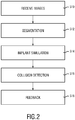
- a method for planning an implantation of a cardiac implant in accordance to claim 13 which comprises the steps of
- a further characteristic of the present invention is the simulation of the cardiac implant within the target implant region.
- a simple geometrical model may be used to simulate the cardiac implant.
- This simulated cardiac implant may be used to evaluate an overlap with the locally adjacent region that has been segmented prior thereto.
- a feedback unit which may e.g. be realized by a display, then provides feedback information concerning the evaluated overlap to a physician or medical staff.
- the overlap may e.g. be displayed for all evaluated cardiac images. This direct feedback concerning possible collisions of the cardiac implant with parts of the heart based on a plurality of 3D cardiac images is a very powerful tool during planning of such a cardiac implantation.
- the overlap evaluation is not only performed in a subset of the received plurality of 3D cardiac images, but in all of the received 3D cardiac images. In this way, the amount of overlap data is further increased, such that the overlap evaluation is refined.
- the overlap data may therefore be evaluated for a whole timely consecutive imaging sequence, meaning that the overlap of the locally adjacent region (e.g. the mitral valve leaflet) with the virtual cardiac implant may be calculated time-dependent over a complete cardiac cycle.
- the collision evaluation unit is further configured to determine for each of the plurality of different spatial locations a maximum overlap by comparing the overlaps in the 3D cardiac images at the respective spatial locations with each other.
- the segmentation unit is configured to simulate the cardiac implant by means of a virtual model having an elliptical cross-section, wherein a normal to the elliptical cross-section coincides with a longitudinal axis along which the target implant region substantially extends.
- the segmentation unit is configured to segment the target implant region and the locally adjacent region based on a model-based segmentation.
- the model-based segmentation may, for example, be conducted in a similar manner as this is described for a model-based segmentation of CT images in Ecabert, O. et al. "Automatic model-based segmentation of the heart in CT images", IEEE Transactions on Medical Imaging, Vol. 27(9), pp. 1189-1291, 2008 , which is herein incorporated by reference.
- This model-based segmentation makes use of a geometrical mesh model of the anatomical structures of the heart and may comprise respective segments representing respective anatomic features of the heart.
- Such a model-based segmentation usually starts with the identification of the position and orientation of the heart within the 3D image data. This may, for example, be done using a 3D implementation of the Generalized Hough Transform.
- the receiving unit 12 may be an interface (either internal or external interface) that receives the 3D cardiac images 14, 14' and transfers them to a processing unit 20.
- This processing unit 20 may be implemented as a CPU or a microprocessor within the medical imaging system 10. It may, for example, be a part of a personal computer that has software stored thereon that is programmed to carry out the below explained method according to the present invention.
- the segmentation unit 22 is configured to segment the plurality of the 3D cardiac images 14, 14'. In case of a 4D TEE sequence, each frame is segmented.
- the simulation unit 24 is configured to simulate a model of a cardiac implant as well as to simulate the implantation of the cardiac implant in the 3D cardiac images 14, 14'.
- the collision evaluation unit 26 then evaluates an overlap of the simulated cardiac implant with anatomical features that have been segmented in the 3D cardiac images 14, 14'. The results of this evaluation may be finally shown to a user (e.g. a physician) by means of a feedback unit (FU) 28 that could be realized as a display or a screen.
- FU feedback unit
- anatomical features of interest are segmented in order to being able to simulate the movement of these anatomical features over time.
- Anatomical features that are of particular interest in a TAVI are the aortic valve, the left ventricular outflow tract, into which the cardiac implant is inserted, as well as the anterior mitral leaflet, since, depending on the position and size of the cardiac implant, the anterior mitral leaflet may collide with the medical implant during its natural movement.
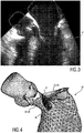
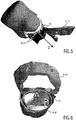
- Fig. 3 shows a TEE ultrasound image from which it can be seen that the anterior mitral leaflet 34 in its open position at least partly extends into the left ventricular outflow tract 36 where the medical implant may be placed.
- the left ventricular outflow tract 36 is therefore denoted as target implant region 38
- the anterior mitral valve leaflet 34 is denoted as locally adjacent region 40 that could interfere with the cardiac implant 42, as this is schematically illustrated in Fig. 4 .
- the target implant region 38 and the locally adjacent region 40 are segmented in a multi-step approach in order to determine the dynamics of the left ventricular outflow tract 36 and the anterior mitral leaflet 34.
- the model that is used thereto is represented as a triangular surface model with mean shape m .
- the heart position is located using an adapted Generalized Hough Transform.
- it is iteratively refined by determining the parameters of an affine transformation T that minimize the distance to detected boundaries (external energy E ext ).
- multiple iterations of a deformable adaptation are performed that is balanced between attraction to image boundaries ( E ext ) and mean shape preservation ( E int ).
- the cardiac implant 42 and its position within the target implant region 38 is simulated. This is preferably done in each frame of the received 3D image sequence.
- the cardiac implant 42 may thereto be simulated by means of a virtual model having an elliptical cross-section, e.g. the cross-section of the target implant region 38 that has been determined within the segmentation unit 22.
- the elliptical ring 44 determined within the segmentation step S12 may be extended along the z-axis along which the target implant region 38 substantially extends.
- other virtual 3D models of cardiac implants 42 which resemble the shape of a stent in a more realistic manner, may be used in the simulation.
- the user may also manually vary the size, the shape and/or the position of the simulated cardiac implant 42.
- an overlap of the simulated cardiac implant 42 with the segmented locally adjacent region 40 is calculated. In the given example it is calculated to what extent the anterior mitral leaflet 34 projects into the virtual cardiac implant 42. This calculated overlap is schematically illustrated in Fig. 4 and indicated by reference numeral 46. This is preferably done for each frame of the 3D image sequence.
- the collision evaluation unit 26 preferably determines in each of the plurality of 3D cardiac images 14, 14' the overlap at a plurality of different spatial locations along the z-axis in order to receive the overlap information in each frame as a function of the longitudinal axis of the target implant region 38.
- the above-mentioned collision calculation/evaluation may be performed by combining all segmented and registered points of the anterior mitral leaflet 34 that have been found in the segmentation S12 into a point cloud.
- the points of this point cloud may then be merged into groups according to the defined step size. For every group of points, the maximum overlap may then be calculated to receive the maximum overlap at the different positions on the z-axis.
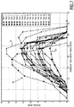
- Figs. 8A and 8B Both images show the heart of two different patients at a point in time during the cardiac cycle when the mitral valve is opened. By comparing the two images with each other, it can be seen that the overlap between the anterior mitral leaflet and the left ventricular outflow tract prolongation is quite different. In Fig. 8A , the overlap has an extent of around 8 mm, while the maximum overlap is located quite far from the aortic annulus plane. In Fig. 8B , the maximum overlap is over 15 mm and located a lot closer to the aortic annulus plane.
- a computer program may be stored/distributed on a suitable medium, such as an optical storage medium or a solid-state medium supplied together with or as part of other hardware, but may also be distributed in other forms, such as via the Internet or other wired or wireless telecommunication systems.
- a suitable medium such as an optical storage medium or a solid-state medium supplied together with or as part of other hardware, but may also be distributed in other forms, such as via the Internet or other wired or wireless telecommunication systems.
Claims (14)
- Système d'imagerie médicale (10) pour planifier une implantation d'un implant cardiaque (42), comprenant:- une unité de réception (12) configurée pour recevoir une pluralité d'images cardiaques tridimensionnelles (3D) (14, 14') montrant des différentes conditions d'un cœur (32) pendant un cycle cardiaque;- une unité de segmentation (22) configurée pour segmenter dans la pluralité d'images cardiaques 3D (14, 14') une région d'implant cible (38) et une région localement adjacente (40) qui pourrait interférer avec l'implant cardiaque (42), où la région d'implant cible (38) fait partie d'un tractus de sortie ventriculaire gauche (LVOT) (36) et la région localement adjacente (40) fait partie d'une valve mitrale (MV) (34);- une unité de simulation (24) configurée pour simuler l'implantation de l'implant cardiaque (42) dans la région d'implant cible (40) dans au moins deux parmi la pluralité d'images cardiaques 3D (14, 14');- une unité d'évaluation de collision (26) configurée pour évaluer un chevauchement (46) de l'implant cardiaque simulé (42) avec la région localement adjacente segmentée (40) en correspondance d'une pluralité d'emplacements spatiaux différents le long d'un axe longitudinal (z) le long duquel la région d'implant cible (38) s'étend sensiblement dans les au moins deux parmi la pluralité d'images cardiaques 3D (14, 14'); et- une unité de rétroaction (28) configurée pour fournir des informations en retour à un utilisateur concernant le chevauchement évalué (46).
- Système d'imagerie médicale selon la revendication 1, dans lequel l'unité de simulation (24) est configurée pour simuler l'implantation de l'implant cardiaque (42) dans la région d'implant cible (38) dans chacune parmi la pluralité d'images cardiaques 3D (14, 14'), et dans lequel l'unité d'évaluation de collision (26) est configurée pour évaluer le chevauchement (46) de l'implant cardiaque simulé (42) avec la région localement adjacente segmentée (40) dans chacune parmi la pluralité d'images cardiaques 3D (14, 14').
- Système d'imagerie médicale selon la revendication 1 ou 2, dans lequel l'unité de rétroaction (28) est configurée pour fournir des informations en retour à l'utilisateur concernant le chevauchement évalué (46) dans chacune parmi la pluralité d'images cardiaques 3D (14, 14').
- Système d'imagerie médicale selon l'une quelconque des revendications 1 à 3, dans lequel les informations en retour fournies par l'unité de rétroaction (28) comprennent une étendue quantifiée du chevauchement (46) et/ou un emplacement où le chevauchement (46) se produit dans les images cardiaques 3D (14, 14').
- Système d'imagerie médicale selon l'une quelconque des revendications 1 à 4, dans lequel l'unité d'évaluation de collision (26) est en outre configurée pour déterminer pour chacun parmi la pluralité d'emplacements spatiaux différents un chevauchement maximal (46) en comparant les chevauchements (46) dans les images cardiaques 3D (14, 14') en correspondance des emplacements spatiaux respectifs les uns avec les autres.
- Système d'imagerie médicale selon la revendication 5, dans lequel l'unité de rétroaction (28) est configurée pour fournir une représentation graphique (48) illustrant les chevauchements maximaux (46) en fonction des différents emplacements spatiaux le long de l'axe longitudinal (z).
- Système d'imagerie médicale selon l'une quelconque des revendications 1 à 6, dans lequel l'unité de simulation (24) est configurée pour simuler l'implant cardiaque (42) au moyen d'un modèle virtuel ayant une section transversale elliptique, où une normale à la section transversale elliptique coïncide avec l'axe longitudinal (z) le long duquel la région d'implant cible (38) s'étend sensiblement.
- Système d'imagerie médicale selon l'une quelconque des revendications 1 à 7, comprenant en outre une interface d'entrée (30) qui permet à un utilisateur de faire varier une taille, une forme et/ou une position de l'implant cardiaque simulé (42).
- Système d'imagerie médicale selon l'une quelconque des revendications 1 à 8, dans lequel l'unité de segmentation (22) est configurée pour segmenter la région d'implant cible (38) et la région localement adjacente (40) sur la base d'une segmentation basée sur un modèle.
- Système d'imagerie médicale selon l'une quelconque des revendications 1 à 9, dans lequel la pluralité d'images 3D cardiaques (14, 14') sont des images d'échocardiographie transoesophagienne 3D (TEE) acquises avec un système d'imagerie par ultrasons.
- Système d'imagerie médicale (10) pour planifier une implantation d'un implant cardiaque (42), comprenant:- une unité de réception (12) configurée pour recevoir une pluralité d'images cardiaques tridimensionnelles (3D) (14, 14') montrant des différentes conditions d'un cœur (32) pendant un cycle cardiaque;- une unité de segmentation (22) configurée pour segmenter dans la pluralité d'images cardiaques 3D (14, 14') une région d'implant cible (38) et une région localement adjacente (40) qui pourrait interférer avec l'implant cardiaque (42), où la région d'implant cible (38) fait partie d'un tractus de sortie ventriculaire droite (RVOT) et la région localement adjacente (40) fait partie d'une valve tricuspide (TV);- une unité de simulation (24) configurée pour simuler l'implantation de l'implant cardiaque (42) dans la région d'implant cible (40) dans au moins deux parmi la pluralité d'images cardiaques 3D (14, 14');- une unité d'évaluation de collision (26) configurée pour évaluer un chevauchement (46) de l'implant cardiaque simulé (42) avec la région localement adjacente segmentée (40) en correspondance d'une pluralité d'emplacements spatiaux différents le long d'un axe longitudinal (z) le long duquel la région d'implant cible (38) s'étend sensiblement dans les au moins deux parmi la pluralité d'images cardiaques 3D (14, 14'); et- une unité de rétroaction (28) configurée pour fournir des informations en retour à un utilisateur concernant le chevauchement évalué (46).
- Procédé pour planifier une implantation d'un implant cardiaque, comprenant les étapes de:- recevoir une pluralité d'images cardiaques tridimensionnelles (3D) (14, 14') montrant des différentes conditions d'un cœur (32) pendant un cycle cardiaque;- segmenter dans la pluralité d'images cardiaques 3D (14, 14') une région d'implant cible (38) et une région localement adjacente (40) qui pourrait interférer avec l'implant cardiaque (42), où la région d'implant cible (38) est une partie d'un tractus de sortie ventriculaire gauche (LVOT) (36) et la région localement adjacente (40) est une partie d'une valve mitrale (MV) (34);- simuler l'implantation de l'implant cardiaque (42) dans la région d'implant cible (38) dans au moins deux parmi la pluralité d'images cardiaques 3D (14, 14');- évaluer un chevauchement (46) de l'implant cardiaque simulé (42) avec la région localement adjacente segmentée (40) en correspondance d'une pluralité d'emplacements spatiaux différents le long d'un axe longitudinal (z) le long duquel la région d'implant cible (38) s'étend sensiblement dans les au moins deux parmi la pluralité d'images cardiaques 3D (14, 14'); et- fournir des informations en retour à un utilisateur concernant le chevauchement évalué (46).
- Procédé pour planifier une implantation d'un implant cardiaque, comprenant les étapes de:- recevoir une pluralité d'images cardiaques tridimensionnelles (3D) (14, 14') montrant des différentes conditions d'un cœur (32) pendant un cycle cardiaque;- segmenter dans la pluralité d'images cardiaques 3D (14, 14') une région d'implant cible (38) et une région localement adjacente (40) qui pourrait interférer avec l'implant cardiaque (42), où la région d'implant cible (38) est une partie d'un tractus de sortie ventriculaire droite (RVOT) et la région localement adjacente (40) est une partie d'une valve tricuspide (TV);- simuler l'implantation de l'implant cardiaque (42) dans la région d'implant cible (38) dans au moins deux parmi la pluralité d'images cardiaques 3D (14, 14');- évaluer un chevauchement (46) de l'implant cardiaque simulé (42) avec la région localement adjacente segmentée (40) en correspondance d'une pluralité d'emplacements spatiaux différents le long d'un axe longitudinal (z) le long duquel la région d'implant cible (38) s'étend sensiblement dans les au moins deux parmi la pluralité d'images cardiaques 3D (14, 14'); et- fournir des informations en retour à un utilisateur concernant le chevauchement évalué (46).
- Programme d'ordinateur comprenant des moyens de code de programme pour amener un ordinateur à exécuter les étapes du procédé selon l'une quelconque des revendications 12 et 13 lorsque ledit programme d'ordinateur est exécuté sur un ordinateur.
Priority Applications (1)
| Application Number | Priority Date | Filing Date | Title |
|---|---|---|---|
| EP14727498.9A EP3005310B1 (fr) | 2013-06-07 | 2014-05-30 | Planification d'une implantation d'un implant cardiaque |
Applications Claiming Priority (3)
| Application Number | Priority Date | Filing Date | Title |
|---|---|---|---|
| EP13170984 | 2013-06-07 | ||
| PCT/EP2014/061254 WO2014195237A1 (fr) | 2013-06-07 | 2014-05-30 | Planification d'une implantation d'un implant cardiaque |
| EP14727498.9A EP3005310B1 (fr) | 2013-06-07 | 2014-05-30 | Planification d'une implantation d'un implant cardiaque |
Publications (2)
| Publication Number | Publication Date |
|---|---|
| EP3005310A1 EP3005310A1 (fr) | 2016-04-13 |
| EP3005310B1 true EP3005310B1 (fr) | 2021-01-13 |
Family
ID=48792951
Family Applications (1)
| Application Number | Title | Priority Date | Filing Date |
|---|---|---|---|
| EP14727498.9A Active EP3005310B1 (fr) | 2013-06-07 | 2014-05-30 | Planification d'une implantation d'un implant cardiaque |
Country Status (5)
| Country | Link |
|---|---|
| US (2) | US9956046B2 (fr) |
| EP (1) | EP3005310B1 (fr) |
| JP (1) | JP6382304B2 (fr) |
| CN (1) | CN105264573B (fr) |
| WO (1) | WO2014195237A1 (fr) |
Families Citing this family (12)
| Publication number | Priority date | Publication date | Assignee | Title |
|---|---|---|---|---|
| US9333044B2 (en) * | 2011-12-30 | 2016-05-10 | St. Jude Medical, Atrial Fibrillation Division, Inc. | System and method for detection and avoidance of collisions of robotically-controlled medical devices |
| CN103312727A (zh) * | 2012-03-06 | 2013-09-18 | 创业软件股份有限公司 | 一种区域医疗协同服务领域云计算部署方法 |
| CA2949686C (fr) | 2014-05-20 | 2019-03-19 | Materialise N.V. | Systeme et procede de quantification de valve |
| JP6411073B2 (ja) * | 2014-06-02 | 2018-10-24 | キヤノンメディカルシステムズ株式会社 | 医用画像処理装置および医用画像処理方法 |
| EP4193928A1 (fr) | 2015-03-10 | 2023-06-14 | Koninklijke Philips N.V. | Diagnostic ultrasonore de performance cardiaque utilisant une segmentation de chambre de modèle cardiaque avec commande d'utilisateur |
| US9931790B2 (en) * | 2015-04-16 | 2018-04-03 | Siemens Healthcare Gmbh | Method and system for advanced transcatheter aortic valve implantation planning |
| JP7181216B2 (ja) | 2017-03-31 | 2022-11-30 | コーニンクレッカ フィリップス エヌ ヴェ | 経カテーテル大動脈弁移植術(tavi)が冠血流量及び冠動脈圧に及ぼす影響のシミュレーション |
| EP3422226A1 (fr) * | 2017-06-29 | 2019-01-02 | Koninklijke Philips N.V. | Dispositif et procédé de prédiction d'un état déplié d'un implant pliable dans un tissu cardiovasculaire |
| CN108230431B (zh) * | 2018-01-24 | 2022-07-12 | 深圳市云之梦科技有限公司 | 一种二维虚拟形象的人体动作动画生成方法及系统 |
| EP3542757A1 (fr) * | 2018-03-23 | 2019-09-25 | FEops NV | Procédé et système d'intervention cardiaque structurelle percutanée virtuelle spécifique à un patient |
| EP3944252A1 (fr) * | 2020-07-21 | 2022-01-26 | Virtonomy GmbH | Système d'évaluation automatique de raccord de patient virtuel de dispositifs médicaux |
| CN113796992A (zh) * | 2021-09-26 | 2021-12-17 | 上海市同济医院 | 一种基于图像分割的自动化瓣膜支架输送系统 |
Family Cites Families (14)
| Publication number | Priority date | Publication date | Assignee | Title |
|---|---|---|---|---|
| DE602004028471D1 (de) | 2003-06-13 | 2010-09-16 | Philips Intellectual Property | Dreidimensionale bildsegmentierung |
| CN100493460C (zh) * | 2007-04-12 | 2009-06-03 | 中国人民解放军第三军医大学第一附属医院 | 一种虚拟经食道超声心动图系统 |
| DE102007039207A1 (de) * | 2007-08-20 | 2009-02-26 | Siemens Ag | Berechnungsverfahren zur Detektierung von Kollisionen mittels eines Drahtgittermodells repräsentierter räumlicher Objekte sowie Vorrichtung zur Dimensionierung medizinischer Y-Stents |
| US7970719B2 (en) * | 2008-06-06 | 2011-06-28 | Siemens Aktiengesellschaft | Method and simulation device for structurally individualized simulation of the introduction of a wall support element into a section of a tubular structure |
| US9715637B2 (en) | 2009-03-18 | 2017-07-25 | Siemens Healthcare Gmbh | Method and system for automatic aorta segmentation |
| EP2427142B1 (fr) * | 2009-05-08 | 2017-11-01 | Koninklijke Philips N.V. | Planification et guidage par ultrasons de dispositifs médicaux implantables |
| US9135704B2 (en) * | 2009-06-24 | 2015-09-15 | Koninklijke Philips N.V. | Spatial and shape characterization of an implanted device within an object |
| US10719986B2 (en) * | 2009-12-22 | 2020-07-21 | Siemens Healthcare Gmbh | Method and system for virtual percutaneous valve implantation |
| US9202271B2 (en) | 2010-04-21 | 2015-12-01 | Koninklijke Philips N.V. | Method for determining a physical property of an object, system, computer readable medium and program element |
| US8620050B2 (en) | 2010-09-23 | 2013-12-31 | Siemens Aktiengesellschaft | System and method for 2-D/3-D registration between 3-D volume and 2-D angiography |
| US9058664B2 (en) | 2011-09-07 | 2015-06-16 | Siemens Aktiengesellschaft | 2D-2D fusion for interventional guidance in trans-catheter aortic valve implantation |
| US8938283B2 (en) * | 2011-12-01 | 2015-01-20 | Neochord, Inc. | Surgical navigation for repair of heart valve leaflets |
| US10789772B2 (en) * | 2012-05-16 | 2020-09-29 | Feops Nv | Pre-operative simulation of trans-catheter valve implantation |
| JP2016501636A (ja) * | 2012-12-21 | 2016-01-21 | ヴォルカノ コーポレイションVolcano Corporation | 医療イメージングシステム用の適応インターフェイス |
-
2014
- 2014-05-30 WO PCT/EP2014/061254 patent/WO2014195237A1/fr active Application Filing
- 2014-05-30 EP EP14727498.9A patent/EP3005310B1/fr active Active
- 2014-05-30 JP JP2016517250A patent/JP6382304B2/ja active Active
- 2014-05-30 CN CN201480032065.2A patent/CN105264573B/zh active Active
- 2014-05-30 US US14/895,604 patent/US9956046B2/en active Active
-
2018
- 2018-04-04 US US15/944,919 patent/US10695131B2/en active Active
Non-Patent Citations (1)
| Title |
|---|
| None * |
Also Published As
| Publication number | Publication date |
|---|---|
| US20180289424A1 (en) | 2018-10-11 |
| US9956046B2 (en) | 2018-05-01 |
| JP2016526954A (ja) | 2016-09-08 |
| CN105264573B (zh) | 2019-07-02 |
| US20160128786A1 (en) | 2016-05-12 |
| US10695131B2 (en) | 2020-06-30 |
| EP3005310A1 (fr) | 2016-04-13 |
| JP6382304B2 (ja) | 2018-08-29 |
| CN105264573A (zh) | 2016-01-20 |
| WO2014195237A1 (fr) | 2014-12-11 |
Similar Documents
| Publication | Publication Date | Title |
|---|---|---|
| US10695131B2 (en) | Medical imaging system | |
| EP3081161B1 (fr) | Procédé et système pour planification d'implantation de valvule aortique transcathéter avancée | |
| US10719986B2 (en) | Method and system for virtual percutaneous valve implantation | |
| US8682626B2 (en) | Method and system for comprehensive patient-specific modeling of the heart | |
| Olabarriaga et al. | Segmentation of thrombus in abdominal aortic aneurysms from CTA with nonparametric statistical grey level appearance modeling | |
| CN106716488B (zh) | 分析主动脉瓣钙化 | |
| US20210022806A1 (en) | Method and system for patient-specific virtual percutaneous structural heart intervention | |
| US20110052026A1 (en) | Method and Apparatus for Determining Angulation of C-Arm Image Acquisition System for Aortic Valve Implantation | |
| EP3555846B1 (fr) | Prédiction de contrainte et évaluation de contrainte pour l'insertion d'un dispositif dans un objet déformable | |
| Tahoces et al. | Deep learning method for aortic root detection | |
| EP2912633A1 (fr) | Simulation d'objets dans un atlas et enregistrement de données de patient contenant une structure spécifique sur des données d'atlas | |
| Cristoforetti et al. | A patient-specific mass-spring model for biomechanical simulation of aortic root tissue during transcatheter aortic valve implantation | |
| Ionasec et al. | Personalized modeling and assessment of the aortic-mitral coupling from 4D TEE and CT | |
| Chen et al. | Image registration-based method for reconstructing transcatheter heart valve geometry from patient-specific CT scans | |
| Weber et al. | Analysis of mitral valve motion in 4D transesophageal echocardiography for transcatheter aortic valve implantation | |
| EP4227953A1 (fr) | Procédé et système de détermination d'un modèle d'implant cardiaque | |
| Bosmans et al. | Aortic root sizing for transcatheter aortic valve implantation using a shape model parameterisation | |
| Li et al. | Toward patient-specific computational study of aortic diseases: a population based shape modeling approach | |
| Ionasec et al. | Patient-specific modeling of the heart: applications to cardiovascular disease management | |
| WO2022241431A1 (fr) | Systèmes et procédés de reconstruction de géométrie de dispositif implantable à partir d'examens d'imagerie spécifiques à un patient | |
| Book | Modeling of Aortic Valve Anatomic Geometry from Clinical Multi Detector-Row Computed Tomography Images | |
| Agyei-Ntim | Statistical Shape Modeling of the Right Ventricle in Pediatric Pulmonary Hypertension | |
| Ionasec | Patient-specific modeling and quantification of the heart valves from multimodal cardiac images | |
| Voigt et al. | Computational Decision Support for Percutaneous Aortic Valve Implantation |
Legal Events
| Date | Code | Title | Description |
|---|---|---|---|
| PUAI | Public reference made under article 153(3) epc to a published international application that has entered the european phase |
Free format text: ORIGINAL CODE: 0009012 |
|
| 17P | Request for examination filed |
Effective date: 20160107 |
|
| AK | Designated contracting states |
Kind code of ref document: A1 Designated state(s): AL AT BE BG CH CY CZ DE DK EE ES FI FR GB GR HR HU IE IS IT LI LT LU LV MC MK MT NL NO PL PT RO RS SE SI SK SM TR |
|
| AX | Request for extension of the european patent |
Extension state: BA ME |
|
| DAX | Request for extension of the european patent (deleted) | ||
| STAA | Information on the status of an ep patent application or granted ep patent |
Free format text: STATUS: EXAMINATION IS IN PROGRESS |
|
| 17Q | First examination report despatched |
Effective date: 20190926 |
|
| RAP1 | Party data changed (applicant data changed or rights of an application transferred) |
Owner name: KONINKLIJKE PHILIPS N.V. Owner name: PHILIPS GMBH |
|
| GRAP | Despatch of communication of intention to grant a patent |
Free format text: ORIGINAL CODE: EPIDOSNIGR1 |
|
| STAA | Information on the status of an ep patent application or granted ep patent |
Free format text: STATUS: GRANT OF PATENT IS INTENDED |
|
| INTG | Intention to grant announced |
Effective date: 20200629 |
|
| RIN1 | Information on inventor provided before grant (corrected) |
Inventor name: STEHLE, THOMAS HEIKO Inventor name: WAECHTER-STEHLE, IRINA Inventor name: WEBER, FRANK MICHAEL Inventor name: PETERS, JOCHEN Inventor name: WEESE, JUERGEN |
|
| GRAS | Grant fee paid |
Free format text: ORIGINAL CODE: EPIDOSNIGR3 |
|
| GRAA | (expected) grant |
Free format text: ORIGINAL CODE: 0009210 |
|
| STAA | Information on the status of an ep patent application or granted ep patent |
Free format text: STATUS: THE PATENT HAS BEEN GRANTED |
|
| AK | Designated contracting states |
Kind code of ref document: B1 Designated state(s): AL AT BE BG CH CY CZ DE DK EE ES FI FR GB GR HR HU IE IS IT LI LT LU LV MC MK MT NL NO PL PT RO RS SE SI SK SM TR |
|
| REG | Reference to a national code |
Ref country code: GB Ref legal event code: FG4D |
|
| REG | Reference to a national code |
Ref country code: CH Ref legal event code: EP |
|
| REG | Reference to a national code |
Ref country code: DE Ref legal event code: R081 Ref document number: 602014074196 Country of ref document: DE Owner name: PHILIPS GMBH, DE Free format text: FORMER OWNER: PHILIPS GMBH, 20099 HAMBURG, DE |
|
| REG | Reference to a national code |
Ref country code: IE Ref legal event code: FG4D |
|
| REG | Reference to a national code |
Ref country code: DE Ref legal event code: R096 Ref document number: 602014074196 Country of ref document: DE |
|
| REG | Reference to a national code |
Ref country code: AT Ref legal event code: REF Ref document number: 1355124 Country of ref document: AT Kind code of ref document: T Effective date: 20210215 |
|
| REG | Reference to a national code |
Ref country code: DE Ref legal event code: R084 Ref document number: 602014074196 Country of ref document: DE |
|
| REG | Reference to a national code |
Ref country code: GB Ref legal event code: 746 Effective date: 20210301 |
|
| REG | Reference to a national code |
Ref country code: AT Ref legal event code: MK05 Ref document number: 1355124 Country of ref document: AT Kind code of ref document: T Effective date: 20210113 |
|
| REG | Reference to a national code |
Ref country code: NL Ref legal event code: MP Effective date: 20210113 |
|
| REG | Reference to a national code |
Ref country code: LT Ref legal event code: MG9D |
|
| PG25 | Lapsed in a contracting state [announced via postgrant information from national office to epo] |
Ref country code: FI Free format text: LAPSE BECAUSE OF FAILURE TO SUBMIT A TRANSLATION OF THE DESCRIPTION OR TO PAY THE FEE WITHIN THE PRESCRIBED TIME-LIMIT Effective date: 20210113 Ref country code: HR Free format text: LAPSE BECAUSE OF FAILURE TO SUBMIT A TRANSLATION OF THE DESCRIPTION OR TO PAY THE FEE WITHIN THE PRESCRIBED TIME-LIMIT Effective date: 20210113 Ref country code: GR Free format text: LAPSE BECAUSE OF FAILURE TO SUBMIT A TRANSLATION OF THE DESCRIPTION OR TO PAY THE FEE WITHIN THE PRESCRIBED TIME-LIMIT Effective date: 20210414 Ref country code: PT Free format text: LAPSE BECAUSE OF FAILURE TO SUBMIT A TRANSLATION OF THE DESCRIPTION OR TO PAY THE FEE WITHIN THE PRESCRIBED TIME-LIMIT Effective date: 20210513 Ref country code: LT Free format text: LAPSE BECAUSE OF FAILURE TO SUBMIT A TRANSLATION OF THE DESCRIPTION OR TO PAY THE FEE WITHIN THE PRESCRIBED TIME-LIMIT Effective date: 20210113 Ref country code: BG Free format text: LAPSE BECAUSE OF FAILURE TO SUBMIT A TRANSLATION OF THE DESCRIPTION OR TO PAY THE FEE WITHIN THE PRESCRIBED TIME-LIMIT Effective date: 20210413 Ref country code: NO Free format text: LAPSE BECAUSE OF FAILURE TO SUBMIT A TRANSLATION OF THE DESCRIPTION OR TO PAY THE FEE WITHIN THE PRESCRIBED TIME-LIMIT Effective date: 20210413 Ref country code: NL Free format text: LAPSE BECAUSE OF FAILURE TO SUBMIT A TRANSLATION OF THE DESCRIPTION OR TO PAY THE FEE WITHIN THE PRESCRIBED TIME-LIMIT Effective date: 20210113 |
|
| PG25 | Lapsed in a contracting state [announced via postgrant information from national office to epo] |
Ref country code: SE Free format text: LAPSE BECAUSE OF FAILURE TO SUBMIT A TRANSLATION OF THE DESCRIPTION OR TO PAY THE FEE WITHIN THE PRESCRIBED TIME-LIMIT Effective date: 20210113 Ref country code: RS Free format text: LAPSE BECAUSE OF FAILURE TO SUBMIT A TRANSLATION OF THE DESCRIPTION OR TO PAY THE FEE WITHIN THE PRESCRIBED TIME-LIMIT Effective date: 20210113 Ref country code: LV Free format text: LAPSE BECAUSE OF FAILURE TO SUBMIT A TRANSLATION OF THE DESCRIPTION OR TO PAY THE FEE WITHIN THE PRESCRIBED TIME-LIMIT Effective date: 20210113 Ref country code: PL Free format text: LAPSE BECAUSE OF FAILURE TO SUBMIT A TRANSLATION OF THE DESCRIPTION OR TO PAY THE FEE WITHIN THE PRESCRIBED TIME-LIMIT Effective date: 20210113 Ref country code: AT Free format text: LAPSE BECAUSE OF FAILURE TO SUBMIT A TRANSLATION OF THE DESCRIPTION OR TO PAY THE FEE WITHIN THE PRESCRIBED TIME-LIMIT Effective date: 20210113 |
|
| PG25 | Lapsed in a contracting state [announced via postgrant information from national office to epo] |
Ref country code: IS Free format text: LAPSE BECAUSE OF FAILURE TO SUBMIT A TRANSLATION OF THE DESCRIPTION OR TO PAY THE FEE WITHIN THE PRESCRIBED TIME-LIMIT Effective date: 20210513 |
|
| REG | Reference to a national code |
Ref country code: DE Ref legal event code: R097 Ref document number: 602014074196 Country of ref document: DE |
|
| PG25 | Lapsed in a contracting state [announced via postgrant information from national office to epo] |
Ref country code: SM Free format text: LAPSE BECAUSE OF FAILURE TO SUBMIT A TRANSLATION OF THE DESCRIPTION OR TO PAY THE FEE WITHIN THE PRESCRIBED TIME-LIMIT Effective date: 20210113 Ref country code: EE Free format text: LAPSE BECAUSE OF FAILURE TO SUBMIT A TRANSLATION OF THE DESCRIPTION OR TO PAY THE FEE WITHIN THE PRESCRIBED TIME-LIMIT Effective date: 20210113 Ref country code: CZ Free format text: LAPSE BECAUSE OF FAILURE TO SUBMIT A TRANSLATION OF THE DESCRIPTION OR TO PAY THE FEE WITHIN THE PRESCRIBED TIME-LIMIT Effective date: 20210113 |
|
| PLBE | No opposition filed within time limit |
Free format text: ORIGINAL CODE: 0009261 |
|
| STAA | Information on the status of an ep patent application or granted ep patent |
Free format text: STATUS: NO OPPOSITION FILED WITHIN TIME LIMIT |
|
| PG25 | Lapsed in a contracting state [announced via postgrant information from national office to epo] |
Ref country code: RO Free format text: LAPSE BECAUSE OF FAILURE TO SUBMIT A TRANSLATION OF THE DESCRIPTION OR TO PAY THE FEE WITHIN THE PRESCRIBED TIME-LIMIT Effective date: 20210113 Ref country code: SK Free format text: LAPSE BECAUSE OF FAILURE TO SUBMIT A TRANSLATION OF THE DESCRIPTION OR TO PAY THE FEE WITHIN THE PRESCRIBED TIME-LIMIT Effective date: 20210113 Ref country code: DK Free format text: LAPSE BECAUSE OF FAILURE TO SUBMIT A TRANSLATION OF THE DESCRIPTION OR TO PAY THE FEE WITHIN THE PRESCRIBED TIME-LIMIT Effective date: 20210113 Ref country code: ES Free format text: LAPSE BECAUSE OF FAILURE TO SUBMIT A TRANSLATION OF THE DESCRIPTION OR TO PAY THE FEE WITHIN THE PRESCRIBED TIME-LIMIT Effective date: 20210113 |
|
| 26N | No opposition filed |
Effective date: 20211014 |
|
| REG | Reference to a national code |
Ref country code: CH Ref legal event code: PL |
|
| PG25 | Lapsed in a contracting state [announced via postgrant information from national office to epo] |
Ref country code: CH Free format text: LAPSE BECAUSE OF NON-PAYMENT OF DUE FEES Effective date: 20210531 Ref country code: AL Free format text: LAPSE BECAUSE OF FAILURE TO SUBMIT A TRANSLATION OF THE DESCRIPTION OR TO PAY THE FEE WITHIN THE PRESCRIBED TIME-LIMIT Effective date: 20210113 Ref country code: LI Free format text: LAPSE BECAUSE OF NON-PAYMENT OF DUE FEES Effective date: 20210531 Ref country code: MC Free format text: LAPSE BECAUSE OF FAILURE TO SUBMIT A TRANSLATION OF THE DESCRIPTION OR TO PAY THE FEE WITHIN THE PRESCRIBED TIME-LIMIT Effective date: 20210113 Ref country code: LU Free format text: LAPSE BECAUSE OF NON-PAYMENT OF DUE FEES Effective date: 20210530 |
|
| REG | Reference to a national code |
Ref country code: BE Ref legal event code: MM Effective date: 20210531 |
|
| PG25 | Lapsed in a contracting state [announced via postgrant information from national office to epo] |
Ref country code: SI Free format text: LAPSE BECAUSE OF FAILURE TO SUBMIT A TRANSLATION OF THE DESCRIPTION OR TO PAY THE FEE WITHIN THE PRESCRIBED TIME-LIMIT Effective date: 20210113 |
|
| PG25 | Lapsed in a contracting state [announced via postgrant information from national office to epo] |
Ref country code: IT Free format text: LAPSE BECAUSE OF FAILURE TO SUBMIT A TRANSLATION OF THE DESCRIPTION OR TO PAY THE FEE WITHIN THE PRESCRIBED TIME-LIMIT Effective date: 20210113 Ref country code: IE Free format text: LAPSE BECAUSE OF NON-PAYMENT OF DUE FEES Effective date: 20210530 |
|
| PG25 | Lapsed in a contracting state [announced via postgrant information from national office to epo] |
Ref country code: IS Free format text: LAPSE BECAUSE OF FAILURE TO SUBMIT A TRANSLATION OF THE DESCRIPTION OR TO PAY THE FEE WITHIN THE PRESCRIBED TIME-LIMIT Effective date: 20210513 Ref country code: FR Free format text: LAPSE BECAUSE OF NON-PAYMENT OF DUE FEES Effective date: 20210531 |
|
| PG25 | Lapsed in a contracting state [announced via postgrant information from national office to epo] |
Ref country code: BE Free format text: LAPSE BECAUSE OF NON-PAYMENT OF DUE FEES Effective date: 20210531 |
|
| PG25 | Lapsed in a contracting state [announced via postgrant information from national office to epo] |
Ref country code: HU Free format text: LAPSE BECAUSE OF FAILURE TO SUBMIT A TRANSLATION OF THE DESCRIPTION OR TO PAY THE FEE WITHIN THE PRESCRIBED TIME-LIMIT; INVALID AB INITIO Effective date: 20140530 |
|
| PG25 | Lapsed in a contracting state [announced via postgrant information from national office to epo] |
Ref country code: CY Free format text: LAPSE BECAUSE OF FAILURE TO SUBMIT A TRANSLATION OF THE DESCRIPTION OR TO PAY THE FEE WITHIN THE PRESCRIBED TIME-LIMIT Effective date: 20210113 |
|
| PGFP | Annual fee paid to national office [announced via postgrant information from national office to epo] |
Ref country code: DE Payment date: 20220628 Year of fee payment: 10 |
|
| PGFP | Annual fee paid to national office [announced via postgrant information from national office to epo] |
Ref country code: GB Payment date: 20230523 Year of fee payment: 10 |