EP3005310B1 - Planning an implantation of a cardiac implant - Google Patents
Planning an implantation of a cardiac implant Download PDFInfo
- Publication number
- EP3005310B1 EP3005310B1 EP14727498.9A EP14727498A EP3005310B1 EP 3005310 B1 EP3005310 B1 EP 3005310B1 EP 14727498 A EP14727498 A EP 14727498A EP 3005310 B1 EP3005310 B1 EP 3005310B1
- Authority
- EP
- European Patent Office
- Prior art keywords
- cardiac
- implant
- images
- region
- overlap
- Prior art date
- Legal status (The legal status is an assumption and is not a legal conclusion. Google has not performed a legal analysis and makes no representation as to the accuracy of the status listed.)
- Active
Links
Images


Classifications
-
- G—PHYSICS
- G06—COMPUTING; CALCULATING OR COUNTING
- G06T—IMAGE DATA PROCESSING OR GENERATION, IN GENERAL
- G06T19/00—Manipulating 3D models or images for computer graphics
-
- A—HUMAN NECESSITIES
- A61—MEDICAL OR VETERINARY SCIENCE; HYGIENE
- A61B—DIAGNOSIS; SURGERY; IDENTIFICATION
- A61B34/00—Computer-aided surgery; Manipulators or robots specially adapted for use in surgery
- A61B34/10—Computer-aided planning, simulation or modelling of surgical operations
-
- A—HUMAN NECESSITIES
- A61—MEDICAL OR VETERINARY SCIENCE; HYGIENE
- A61B—DIAGNOSIS; SURGERY; IDENTIFICATION
- A61B8/00—Diagnosis using ultrasonic, sonic or infrasonic waves
- A61B8/08—Detecting organic movements or changes, e.g. tumours, cysts, swellings
- A61B8/0883—Detecting organic movements or changes, e.g. tumours, cysts, swellings for diagnosis of the heart
-
- A—HUMAN NECESSITIES
- A61—MEDICAL OR VETERINARY SCIENCE; HYGIENE
- A61B—DIAGNOSIS; SURGERY; IDENTIFICATION
- A61B8/00—Diagnosis using ultrasonic, sonic or infrasonic waves
- A61B8/12—Diagnosis using ultrasonic, sonic or infrasonic waves in body cavities or body tracts, e.g. by using catheters
-
- G—PHYSICS
- G06—COMPUTING; CALCULATING OR COUNTING
- G06T—IMAGE DATA PROCESSING OR GENERATION, IN GENERAL
- G06T7/00—Image analysis
- G06T7/0002—Inspection of images, e.g. flaw detection
- G06T7/0012—Biomedical image inspection
- G06T7/0014—Biomedical image inspection using an image reference approach
- G06T7/0016—Biomedical image inspection using an image reference approach involving temporal comparison
-
- G—PHYSICS
- G06—COMPUTING; CALCULATING OR COUNTING
- G06T—IMAGE DATA PROCESSING OR GENERATION, IN GENERAL
- G06T7/00—Image analysis
- G06T7/10—Segmentation; Edge detection
- G06T7/174—Segmentation; Edge detection involving the use of two or more images
-
- G—PHYSICS
- G06—COMPUTING; CALCULATING OR COUNTING
- G06T—IMAGE DATA PROCESSING OR GENERATION, IN GENERAL
- G06T7/00—Image analysis
- G06T7/20—Analysis of motion
- G06T7/246—Analysis of motion using feature-based methods, e.g. the tracking of corners or segments
- G06T7/251—Analysis of motion using feature-based methods, e.g. the tracking of corners or segments involving models
-
- G—PHYSICS
- G06—COMPUTING; CALCULATING OR COUNTING
- G06T—IMAGE DATA PROCESSING OR GENERATION, IN GENERAL
- G06T7/00—Image analysis
- G06T7/30—Determination of transform parameters for the alignment of images, i.e. image registration
- G06T7/33—Determination of transform parameters for the alignment of images, i.e. image registration using feature-based methods
-
- A—HUMAN NECESSITIES
- A61—MEDICAL OR VETERINARY SCIENCE; HYGIENE
- A61B—DIAGNOSIS; SURGERY; IDENTIFICATION
- A61B34/00—Computer-aided surgery; Manipulators or robots specially adapted for use in surgery
- A61B34/10—Computer-aided planning, simulation or modelling of surgical operations
- A61B2034/101—Computer-aided simulation of surgical operations
- A61B2034/102—Modelling of surgical devices, implants or prosthesis
- A61B2034/104—Modelling the effect of the tool, e.g. the effect of an implanted prosthesis or for predicting the effect of ablation or burring
-
- A—HUMAN NECESSITIES
- A61—MEDICAL OR VETERINARY SCIENCE; HYGIENE
- A61B—DIAGNOSIS; SURGERY; IDENTIFICATION
- A61B34/00—Computer-aided surgery; Manipulators or robots specially adapted for use in surgery
- A61B34/10—Computer-aided planning, simulation or modelling of surgical operations
- A61B2034/107—Visualisation of planned trajectories or target regions
-
- G—PHYSICS
- G06—COMPUTING; CALCULATING OR COUNTING
- G06T—IMAGE DATA PROCESSING OR GENERATION, IN GENERAL
- G06T2207/00—Indexing scheme for image analysis or image enhancement
- G06T2207/10—Image acquisition modality
- G06T2207/10132—Ultrasound image
- G06T2207/10136—3D ultrasound image
-
- G—PHYSICS
- G06—COMPUTING; CALCULATING OR COUNTING
- G06T—IMAGE DATA PROCESSING OR GENERATION, IN GENERAL
- G06T2207/00—Indexing scheme for image analysis or image enhancement
- G06T2207/30—Subject of image; Context of image processing
- G06T2207/30004—Biomedical image processing
- G06T2207/30048—Heart; Cardiac
-
- G—PHYSICS
- G06—COMPUTING; CALCULATING OR COUNTING
- G06T—IMAGE DATA PROCESSING OR GENERATION, IN GENERAL
- G06T2207/00—Indexing scheme for image analysis or image enhancement
- G06T2207/30—Subject of image; Context of image processing
- G06T2207/30004—Biomedical image processing
- G06T2207/30052—Implant; Prosthesis
-
- G—PHYSICS
- G06—COMPUTING; CALCULATING OR COUNTING
- G06T—IMAGE DATA PROCESSING OR GENERATION, IN GENERAL
- G06T2207/00—Indexing scheme for image analysis or image enhancement
- G06T2207/30—Subject of image; Context of image processing
- G06T2207/30241—Trajectory
-
- G—PHYSICS
- G06—COMPUTING; CALCULATING OR COUNTING
- G06T—IMAGE DATA PROCESSING OR GENERATION, IN GENERAL
- G06T2210/00—Indexing scheme for image generation or computer graphics
- G06T2210/21—Collision detection, intersection
-
- G—PHYSICS
- G06—COMPUTING; CALCULATING OR COUNTING
- G06T—IMAGE DATA PROCESSING OR GENERATION, IN GENERAL
- G06T2210/00—Indexing scheme for image generation or computer graphics
- G06T2210/41—Medical
Definitions
- TAVI transcatheter aortic valve implantation
- TAVI is less invasive, its long-term outcome is unclear. A current discussion is therefore, if TAVI is also beneficial for patients with only intermediate risk for valve replacement. Because their expected lifetime is much longer, the long-term benefit of the TAVI implant must be ensured.
- TAVI implant If the TAVI implant is placed too low, i.e. reaching too far into the left ventricular outflow tract, it can impair movement of the anterior mitral leaflet.
- Wambater et al. "Patient specific models for planning and guidance of minimally invasive aortic valve implantation", MICCAI 2010, part I, LNCS 6361, pp. 526-533, 2010, Springer-Verlag Berlin Heidelberg 2010 , present a method to extract the aortic valve anatomy from CT images.
- the therein presented method allows for detection of anatomical landmarks by exploiting the model-based segmentation. This allows to receive a fairly accurate model, in particular of the aortic valve and the coronary ostia.
- the method is also described in WO 2011/132131 A1 , a prior patent application filed by the applicant.
- a method for planning an implantation of a cardiac implant in accordance to claim 13 which comprises the steps of
- a further characteristic of the present invention is the simulation of the cardiac implant within the target implant region.
- a simple geometrical model may be used to simulate the cardiac implant.
- This simulated cardiac implant may be used to evaluate an overlap with the locally adjacent region that has been segmented prior thereto.
- a feedback unit which may e.g. be realized by a display, then provides feedback information concerning the evaluated overlap to a physician or medical staff.
- the overlap may e.g. be displayed for all evaluated cardiac images. This direct feedback concerning possible collisions of the cardiac implant with parts of the heart based on a plurality of 3D cardiac images is a very powerful tool during planning of such a cardiac implantation.
- the overlap evaluation is not only performed in a subset of the received plurality of 3D cardiac images, but in all of the received 3D cardiac images. In this way, the amount of overlap data is further increased, such that the overlap evaluation is refined.
- the overlap data may therefore be evaluated for a whole timely consecutive imaging sequence, meaning that the overlap of the locally adjacent region (e.g. the mitral valve leaflet) with the virtual cardiac implant may be calculated time-dependent over a complete cardiac cycle.
- the collision evaluation unit is further configured to determine for each of the plurality of different spatial locations a maximum overlap by comparing the overlaps in the 3D cardiac images at the respective spatial locations with each other.
- the segmentation unit is configured to simulate the cardiac implant by means of a virtual model having an elliptical cross-section, wherein a normal to the elliptical cross-section coincides with a longitudinal axis along which the target implant region substantially extends.
- the segmentation unit is configured to segment the target implant region and the locally adjacent region based on a model-based segmentation.
- the model-based segmentation may, for example, be conducted in a similar manner as this is described for a model-based segmentation of CT images in Ecabert, O. et al. "Automatic model-based segmentation of the heart in CT images", IEEE Transactions on Medical Imaging, Vol. 27(9), pp. 1189-1291, 2008 , which is herein incorporated by reference.
- This model-based segmentation makes use of a geometrical mesh model of the anatomical structures of the heart and may comprise respective segments representing respective anatomic features of the heart.
- Such a model-based segmentation usually starts with the identification of the position and orientation of the heart within the 3D image data. This may, for example, be done using a 3D implementation of the Generalized Hough Transform.
- the receiving unit 12 may be an interface (either internal or external interface) that receives the 3D cardiac images 14, 14' and transfers them to a processing unit 20.
- This processing unit 20 may be implemented as a CPU or a microprocessor within the medical imaging system 10. It may, for example, be a part of a personal computer that has software stored thereon that is programmed to carry out the below explained method according to the present invention.
- the segmentation unit 22 is configured to segment the plurality of the 3D cardiac images 14, 14'. In case of a 4D TEE sequence, each frame is segmented.
- the simulation unit 24 is configured to simulate a model of a cardiac implant as well as to simulate the implantation of the cardiac implant in the 3D cardiac images 14, 14'.
- the collision evaluation unit 26 then evaluates an overlap of the simulated cardiac implant with anatomical features that have been segmented in the 3D cardiac images 14, 14'. The results of this evaluation may be finally shown to a user (e.g. a physician) by means of a feedback unit (FU) 28 that could be realized as a display or a screen.
- FU feedback unit
- anatomical features of interest are segmented in order to being able to simulate the movement of these anatomical features over time.
- Anatomical features that are of particular interest in a TAVI are the aortic valve, the left ventricular outflow tract, into which the cardiac implant is inserted, as well as the anterior mitral leaflet, since, depending on the position and size of the cardiac implant, the anterior mitral leaflet may collide with the medical implant during its natural movement.
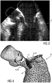
- Fig. 3 shows a TEE ultrasound image from which it can be seen that the anterior mitral leaflet 34 in its open position at least partly extends into the left ventricular outflow tract 36 where the medical implant may be placed.
- the left ventricular outflow tract 36 is therefore denoted as target implant region 38
- the anterior mitral valve leaflet 34 is denoted as locally adjacent region 40 that could interfere with the cardiac implant 42, as this is schematically illustrated in Fig. 4 .
- the target implant region 38 and the locally adjacent region 40 are segmented in a multi-step approach in order to determine the dynamics of the left ventricular outflow tract 36 and the anterior mitral leaflet 34.
- the model that is used thereto is represented as a triangular surface model with mean shape m .
- the heart position is located using an adapted Generalized Hough Transform.
- it is iteratively refined by determining the parameters of an affine transformation T that minimize the distance to detected boundaries (external energy E ext ).
- multiple iterations of a deformable adaptation are performed that is balanced between attraction to image boundaries ( E ext ) and mean shape preservation ( E int ).
- the cardiac implant 42 and its position within the target implant region 38 is simulated. This is preferably done in each frame of the received 3D image sequence.
- the cardiac implant 42 may thereto be simulated by means of a virtual model having an elliptical cross-section, e.g. the cross-section of the target implant region 38 that has been determined within the segmentation unit 22.
- the elliptical ring 44 determined within the segmentation step S12 may be extended along the z-axis along which the target implant region 38 substantially extends.
- other virtual 3D models of cardiac implants 42 which resemble the shape of a stent in a more realistic manner, may be used in the simulation.
- the user may also manually vary the size, the shape and/or the position of the simulated cardiac implant 42.
- an overlap of the simulated cardiac implant 42 with the segmented locally adjacent region 40 is calculated. In the given example it is calculated to what extent the anterior mitral leaflet 34 projects into the virtual cardiac implant 42. This calculated overlap is schematically illustrated in Fig. 4 and indicated by reference numeral 46. This is preferably done for each frame of the 3D image sequence.
- the collision evaluation unit 26 preferably determines in each of the plurality of 3D cardiac images 14, 14' the overlap at a plurality of different spatial locations along the z-axis in order to receive the overlap information in each frame as a function of the longitudinal axis of the target implant region 38.
- the above-mentioned collision calculation/evaluation may be performed by combining all segmented and registered points of the anterior mitral leaflet 34 that have been found in the segmentation S12 into a point cloud.
- the points of this point cloud may then be merged into groups according to the defined step size. For every group of points, the maximum overlap may then be calculated to receive the maximum overlap at the different positions on the z-axis.
- Figs. 8A and 8B Both images show the heart of two different patients at a point in time during the cardiac cycle when the mitral valve is opened. By comparing the two images with each other, it can be seen that the overlap between the anterior mitral leaflet and the left ventricular outflow tract prolongation is quite different. In Fig. 8A , the overlap has an extent of around 8 mm, while the maximum overlap is located quite far from the aortic annulus plane. In Fig. 8B , the maximum overlap is over 15 mm and located a lot closer to the aortic annulus plane.
- a computer program may be stored/distributed on a suitable medium, such as an optical storage medium or a solid-state medium supplied together with or as part of other hardware, but may also be distributed in other forms, such as via the Internet or other wired or wireless telecommunication systems.
- a suitable medium such as an optical storage medium or a solid-state medium supplied together with or as part of other hardware, but may also be distributed in other forms, such as via the Internet or other wired or wireless telecommunication systems.
Description
- The present invention relates to a medical imaging system for planning an implantation of a cardiac implant. Furthermore, the present invention relates to a corresponding method for planning an implantation of a cardiac implant. It also relates to a computer program comprising program code means for causing a computer to carry out the steps of said method. An exemplary technical application of the present invention is the planning of a transcatheter aortic valve implantation (TAVI) for treating aortic stenosis.
- Valvular heart diseases are among the most prominent causes of heart failure and premature cardiac death. Aortic valve stenosis is a very common valvular disease. This disease is often treated by implanting an artificial aortic valve via an open cardiac surgery. This is, however, a very invasive and expensive treatment. In addition, it is considered too high risks or contraindicated for many patients.
- In the last decade, techniques for minimally invasive aortic valve implantation have been developed that offer a new treatment option. An alternative method for high-risk patients that cannot undergo an open-heart surgery for aortic valve replacement is a transcatheter aortic valve implantation (TAVI). In this technique, an artificial valve is mounted on a stent which is delivered through a catheter, either transfemoral, transsubclavian, or transapical, under X-ray guidance, and then expanded in-place.
- Although TAVI is less invasive, its long-term outcome is unclear. A current discussion is therefore, if TAVI is also beneficial for patients with only intermediate risk for valve replacement. Because their expected lifetime is much longer, the long-term benefit of the TAVI implant must be ensured.
- If the TAVI implant is placed too low, i.e. reaching too far into the left ventricular outflow tract, it can impair movement of the anterior mitral leaflet. Case reports demonstrated that contact between the implant and the mitral valve leaflet led to mitral endocarditis and leaflet aneurysms, see e.g. Piazza, N. et al.: "Two cases of aneurysm of the anterior mitral valve leaflet associated with transcatheter aortic valve endocarditis: a mere coincidence?", in Journal of Thoracic and Cardiovascular Surgery 140(3) (2010) e36-e38.
- First, repetitive friction between the implant and the leaflet could damage the leaflet surface. Second, the implant could act as an endocarditis bridge that favors the spread of aortic valve endocarditis to the mitral valve. Especially, the slow tissue degeneration caused by repetitive friction might become more relevant the longer the implant is present.
- Therefore, preparing and planning medical procedures like TAVI before beginning an actual operation is of utmost importance. The treatment planning should particularly make sure to avoid the above explained friction between the implant and any anatomical structure of the heart. Such medical imaging procedures are also important to guide the implantation during the surgery (in real-time), since the aortic valve anatomy is not clearly visible when using X-ray imaging.
- Wächter et al.: "Patient specific models for planning and guidance of minimally invasive aortic valve implantation", MICCAI 2010, part I, LNCS 6361, pp. 526-533, 2010, Springer-Verlag Berlin Heidelberg 2010, present a method to extract the aortic valve anatomy from CT images. The therein presented method allows for detection of anatomical landmarks by exploiting the model-based segmentation. This allows to receive a fairly accurate model, in particular of the aortic valve and the coronary ostia. The method is also described in
WO 2011/132131 A1 , a prior patent application filed by the applicant. - Capelli, C. et al.: "Finite Element Strategies to Satisfy Clinical and Engineering Requirements in the Field of Percutaneous Valves", in Annals of Biomedical Engineering, vol. 40, No. 12, December 2012, pp. 2663-2673 discloses a study showing that beam elements are a convenient choice toward a practical and reliable clinical application of finite element modelling of percutaneous devices for valve implantation. Similar aspects are disclosed in Capelli, C. et al.: "Patient-specific simulations of transcatheter aortic valve stent implantation", in Medical & Biological Engineering & Computing, Springer , Berlin, vol. 50, no. 2, pp. 183-192.
-
US 2011/153286 A1 discloses a method and system for virtual percutaneous valve implantation. A patient-specific anatomical model of a heart valve is estimated based on 3D cardiac medical image data and an implant model representing a valve implant is virtually deployed into the patient-specific anatomical model of the heart valve. A library of implant models, each modeling geometrical properties of a corresponding valve implant, is maintained. The implant models maintained in the library are virtually deployed into the patient specific anatomical model of the heart valve to select an implant type and size and deployment location and orientation for percutaneous valve implantation. - However, there is still need for further improvement of such medical planning systems.
- It is an object of the present invention to provide an improved medical imaging system of the kind mentioned above for planning an implantation of a cardiac implant. It is furthermore an object of the present invention to provide a corresponding method and a computer program for implementing such method.
- These objects are solved by the independent claims. Advantageous embodiments are defined in the dependent claims.
- In a first aspect of the present invention, a medical imaging system for planning an implantation of a cardiac implant in accordance to claim 1 is presented that comprises:
- a receiving unit configured to receive a plurality of three-dimensional (3D) cardiac images showing different conditions of a heart during a cardiac cycle;
- a segmentation unit configured to segment within the plurality of 3D cardiac images a target implant region and a locally adjacent region that could interfere with the cardiac implant, wherein the target implant region is a part of a left ventricular outflow tract and the locally adjacent region is a part of a mitral valve;
- a simulation unit configured to simulate the implantation of the cardiac implant within the target implant region in at least two of the plurality of 3D cardiac images;
- a collision evaluation unit configured to evaluate an overlap of the simulated cardiac implant with the segmented locally adjacent region at a plurality of different spatial locations along a longitudinal axis along which the target implant region substantially extends in the at least two of the plurality of 3D cardiac images; and
- a feedback unit configured to provide feedback information to a user concerning the evaluated overlap.
- In a second aspect of the present invention, a medical imaging system for planning an implantation of a cardiac implant in accordance to claim 11 is presented that comprises:
- a receiving unit configured to receive a plurality of three-dimensional (3D) cardiac images showing different conditions of a heart during a cardiac cycle;
- a segmentation unit configured to segment within the plurality of 3D cardiac images a target implant region and a locally adjacent region that could interfere with the cardiac implant, wherein the target implant region is a part of a right ventricular outflow tract and the locally adjacent region is a part of a tricuspid valve;
- a simulation unit configured to simulate the implantation of the cardiac implant within the target implant region in at least two of the plurality of 3D cardiac images;
- a collision evaluation unit configured to evaluate an overlap of the simulated cardiac implant with the segmented locally adjacent region at a plurality of different spatial locations along a longitudinal axis along which the target implant region substantially extends in the at least two of the plurality of 3D cardiac images; and
- a feedback unit configured to provide feedback information to a user concerning the evaluated overlap.
- In a third aspect of the present invention, a method for planning an implantation of a cardiac implant in accordance to claim 12 is presented, which comprises the steps of
- receiving a plurality of three-dimensional (3D) cardiac images showing different conditions of a heart during a cardiac cycle;
- segmenting within the plurality of 3D cardiac images a target implant region and a locally adjacent region that could interfere with the cardiac implant, wherein the target implant region is a part of a left ventricular outflow tract and the locally adjacent region is a part of a mitral valve;
- simulating the implantation of the cardiac implant within the target implant region in at least two of the plurality of 3D cardiac images;
- evaluating an overlap of the simulated cardiac implant with the segmented locally adjacent region at a plurality of different spatial locations along a longitudinal axis along which the target implant region substantially extends in the at least two of the plurality of 3D cardiac images; and
- providing feedback information to a user concerning the evaluated overlap.
- In a fourth aspect of the present invention, a method for planning an implantation of a cardiac implant in accordance to claim 13 is presented, which comprises the steps of
- receiving a plurality of three-dimensional (3D) cardiac images showing different conditions of a heart during a cardiac cycle;
- segmenting within the plurality of 3D cardiac images a target implant region and a locally adjacent region that could interfere with the cardiac implant, wherein the target implant region is a part of a right ventricular outflow tract and the locally adjacent region is a part of a tricuspid valve;
- simulating the implantation of the cardiac implant within the target implant region in at least two of the plurality of 3D cardiac images;
- evaluating an overlap of the simulated cardiac implant with the segmented locally adjacent region at a plurality of different spatial locations along a longitudinal axis along which the target implant region substantially extends in the at least two of the plurality of 3D cardiac images; and
- providing feedback information to a user concerning the evaluated overlap.
- In a still further aspect of the present invention, a computer program in accordance to claim 14 is presented comprising program code means for causing a computer to carry out the steps of either of the above-mentioned methods when said computer program is carried out on the computer.
- The idea of the invention is to automatically simulate and evaluate the position of the cardiac implant within a plurality of 3D cardiac images based on a segmentation of said images. Said cardiac images may be 3D CT or MRI images. In a preferred embodiment, 3D transesophageal echography (TEE) images acquired with an ultrasound imaging system may be used.
- In contrast to most of the prior art planning systems of this kind, not only one cardiac image but a plurality of such 3D cardiac images are used for the simulation and evaluation. The term "a plurality" shall be understood in the context of the present invention as "at least two". This has a couple of advantages: First, it is tedious to check a series of images for identifying the most relevant image for planning the implantation of the cardiac implant. A doctor or a medical assistant usually has to manually find a suitable image which may be quite time-consuming. Secondly, by evaluating a plurality of 3D cardiac images showing different conditions of the heart during the cardiac cycle, possible unwanted collisions between the cardiac implant and parts of the heart that move during the cardiac cycle may be estimated in a much more precise manner. Depending on the heart movement, the cardiac implant may interfere with one heart region in a first image, but may not interfere with said region of the heart when considering it in another image. Using a plurality of 3D cardiac images for the planning procedure therefore allows to more precisely determining the implant position, the size and shape of the cardiac implant.
- Preferably, the plurality of 3D cardiac images is a sequence of timely consecutive cardiac images showing one or more complete cardiac cycles. By segmenting all of these images, a dynamic segmentation is established which allows to simulate the movement of the heart. This may either be done in a pre-planning step before the actual implantation by means of cardiac images that have been pre-acquired. It may, however, also be done in real-time during the actual implantation.
- A further characteristic of the presented system and method is that not only the target implant region is segmented but also a locally adjacent region of the heart that could, e.g. due to the heart movement, interfere with the cardiac implant. When using the presented system e.g. for TAVI, the target implant region is defined as the left ventricular outflow tract. Depending on the size and position of the TAVI implant it could however also interfere and overlap with the mitral valve leaflet. This mitral valve leaflet would then be considered as locally adjacent region in the meaning of the present invention, such that it will be segmented as well. Since a plurality of 3D cardiac images are used, this allows to evaluate possible overlaps of the TAVI implant with the mitral valve leaflet for different positions of the leaflet during the cardiac cycle. Of course, one would say that the overlap is maximum when the mitral valve is completely open. However, manually finding the image that exactly illustrates the open mitral valve is fairly difficult. Apart from that, collisions of the mitral valve with the cardiac implant may also occur in other states of the mitral valve than the fully open state.
- A further characteristic of the present invention is the simulation of the cardiac implant within the target implant region. Preferably, a simple geometrical model may be used to simulate the cardiac implant. This simulated cardiac implant may be used to evaluate an overlap with the locally adjacent region that has been segmented prior thereto. A feedback unit, which may e.g. be realized by a display, then provides feedback information concerning the evaluated overlap to a physician or medical staff. The overlap may e.g. be displayed for all evaluated cardiac images. This direct feedback concerning possible collisions of the cardiac implant with parts of the heart based on a plurality of 3D cardiac images is a very powerful tool during planning of such a cardiac implantation.
- According to a preferred embodiment, the simulation unit is configured to simulate the implantation of the cardiac implant within the target implant region in each of the plurality of 3D cardiac images, and the collision evaluation unit is configured to evaluate the overlap of the simulated cardiac implant with the segmented locally adjacent region in each of the plurality of 3D cardiac images.
- This means that the overlap evaluation is not only performed in a subset of the received plurality of 3D cardiac images, but in all of the received 3D cardiac images. In this way, the amount of overlap data is further increased, such that the overlap evaluation is refined. The overlap data may therefore be evaluated for a whole timely consecutive imaging sequence, meaning that the overlap of the locally adjacent region (e.g. the mitral valve leaflet) with the virtual cardiac implant may be calculated time-dependent over a complete cardiac cycle.
- Accordingly, the feedback unit is in this embodiment configured to provide feedback information to the user concerning the evaluated overlap in each of the plurality of 3D cardiac images. This feedback information may be displayed for each of the 3D cardiac images separately, but also in an overview for all 3D cardiac images together.
- According to a further embodiment, the feedback information provided by the feedback unit includes a quantified extent of the overlap and/or a location where the overlap occurs in the 3D cardiac images. On a display, it may be exactly shown to the physician at which positions an overlap between the simulated cardiac implant and the segmented locally adjacent region occurs. Furthermore, an indicator about the extent of the overlap may be visualized. It may for example be illustrated on the display that at a given position the overlap has a given size, e.g. a few millimeters.
- According to a further preferred embodiment, the collision evaluation unit is further configured to determine in each of the plurality of 3D cardiac images the overlap at a plurality of different spatial locations along a longitudinal axis along which the target implant region substantially extends. Referring back to the example of using the system for TAVI, this means that the overlap between the virtual implant and the mitral valve leaflet is calculated as a function of the implant depth. The target implant region may then be defined as prolongation of the substantially elliptical left ventricular outflow tract cross-section towards the left ventricle. A coordinate system may be used as an auxiliary means, wherein the longitudinal axis of the left ventricular outflow tract indicates the z-axis. In the above-mentioned embodiment, the collision evaluation unit may determine in each of the plurality of 3D cardiac images the overlap along the z-axis, or in other words, as a function of the z-position.
- In a preferred embodiment, the collision evaluation unit is further configured to determine for each of the plurality of different spatial locations a maximum overlap by comparing the overlaps in the 3D cardiac images at the respective spatial locations with each other.
- In other words, the overlaps evaluated in each of the images may be compared with each other, depending on the position on the z-axis. For each position on the z-axis, one of the plurality of 3D cardiac images is selected in which the most prominent or largest overlap is detected. The result may be a motion analysis of the examined region of the heart that, for example, shows for every or a plurality of positions within the left ventricular outflow tract a maximum overlap of the virtually simulated cardiac implant with the mitral valve leaflet over the whole cardiac cycle.
- In a further preferred embodiment, the feedback unit is configured to provide a graphical representation illustrating the maximum overlaps as a function of the different spatial locations along the longitudinal axis z.
- This graphical representation may be e.g. a graph that shows the maximum overlap on the axis of ordinates in dependency of the position on the longitudinal axis shown along the axis of abscissae. Since the maximum overlap at each position on the longitudinal axis of the target implant region has been found by comparing the overlaps at the respective position in each of the 3D cardiac images, such a graph shows an aggregated overlap information taken from all received 3D cardiac images. The term "maximum overlap" therefore indicates a relative maximum at the respective spatial position, i.e. the highest received overlap value at this spatial position when comparing the received 3D cardiac images with each other at said position.
- Referring back to the TAVI example, it has been shown that these location-dependent maximum overlaps between the anterior mitral leaflet movement and the prolongation of the left ventricular outflow tract vary considerably between different patients. Such an aggregated maximum overlap evaluation could therefore be a good indicator for risk of friction between the mitral valve leaflet and the TAVI implant. It has also been shown that for some patients the absolute maximum overlap (maximum overlap value of all found relative maxima) occurs closer to the aortic valve than for others. The above-mentioned graphical representation may therefore help a physician to identify patient-individual risk zones.
- In a further embodiment of the present invention, the segmentation unit is configured to simulate the cardiac implant by means of a virtual model having an elliptical cross-section, wherein a normal to the elliptical cross-section coincides with a longitudinal axis along which the target implant region substantially extends.
- In case of the above-mentioned TAVI example, an elliptical cross-section is a good approximation for a cross-section of a stent that is to be implanted into the left ventricular outflow tract. The shape or the outer contours of the virtual cardiac implant may therefore be simulated as the prolongation of the elliptical left ventricular outflow tract cross-section towards the left ventricle. The overlap of the mitral valve leaflet may then be calculated by mathematically determining the intersections between the segmented trajectories of the mitral valve leaflet and the elliptical tube model. In order to determine all positions where the mitral valve leaflet extends into the left ventricular outflow tract and its linear prolongation towards the left ventricle, the virtual cardiac implant model may have an infinite length.
- According to a further embodiment, the system may additionally comprise an input interface that allows a user to vary a size, a shape and/or a position of the simulated cardiac implant.
- The overlaps may then be evaluated for different sizes, shapes and positions of the virtual implant to automatically find the best type of implant and the best target implant position. Instead of using simplified models of the implants as mentioned above, also more sophisticated models may be used that resemble the shape and size of the implant in a more realistic way.
- According to a further preferred embodiment, the segmentation unit is configured to segment the target implant region and the locally adjacent region based on a model-based segmentation.
- The model-based segmentation may, for example, be conducted in a similar manner as this is described for a model-based segmentation of CT images in Ecabert, O. et al. "Automatic model-based segmentation of the heart in CT images", IEEE Transactions on Medical Imaging, Vol. 27(9), pp. 1189-1291, 2008, which is herein incorporated by reference. This model-based segmentation makes use of a geometrical mesh model of the anatomical structures of the heart and may comprise respective segments representing respective anatomic features of the heart. Such a model-based segmentation usually starts with the identification of the position and orientation of the heart within the 3D image data. This may, for example, be done using a 3D implementation of the Generalized Hough Transform. Pose misalignment may be corrected by matching the geometrical mesh model to the image, making use of a global similarity transformation. The segmentation comprises an initial model that roughly represents the shape of the anatomical features of the heart. Said model may be a multi-compartment mesh model with triangular meshes. This initial model will be deformed by a transformation. This transformation is decomposed in two transformations of different kinds: a global transformation that can translate, rotate or rescale the initial shape of the geometrical model, if needed, and a local deformation that will actually deform the geometrical model so that it matches more precisely to the anatomical object of interest. This is usually done by defining the normal vectors of the surface of the geometrical model to match the image gradient; that is to say, the segmentation will look in the received 3D imaging data for bright-to-dark edges (or dark-to-bright), which usually represent the tissue borders in the images, i.e. the boundaries of the anatomical features of the heart. Further details how this model-based segmentation may be adapted to the purposes of the herein used dynamic segmentation of moving images (e.g. 4D TEE images) will be explained further below with reference to the drawings.
- In the foregoing description it was mainly referred to the different embodiments of the claimed medical imaging system. It shall be understood that the claimed method has similar and/or identical preferred embodiments as the claimed medical imaging system and as defined in the dependent claims.
- These and other aspects of the invention will be apparent from and elucidated with reference to the embodiment(s) described hereinafter. In the following drawings
-
Fig. 1 shows a schematic block diagram of an embodiment of the medical imaging system according to the present invention; -
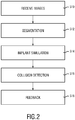
Fig. 2 shows a simplified flow diagram to illustrate an embodiment of the method according to the present invention; -
Fig. 3 shows an exemplary cardiac image that has been segmented according to the method of the present invention; -
Fig. 4 schematically illustrates the results of the segmentation and collision detection according to the present invention; -
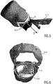
Fig. 5 shows a further model of the heart that may result from the segmentation performed by the presented system; -
Fig. 6 shows the model ofFig. 5 from another side; -
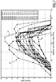
Fig. 7 illustrates different graphs that result from an overlap evaluation according to the present invention; and -
Fig. 8 shows further exemplary segmentations of cardiac images taken from two different patients. -
Fig. 1 shows a simplified and schematic block diagram to illustrate the principal components of the presented medical imaging system, which may be particularly used for planning an implantation of a cardiac implant. The medical imaging system is therein in its entirety denoted withreference numeral 10. - It comprises a receiving unit (RU) 12 which is configured to receive a plurality of 3D
cardiac images 14. Said plurality of 3Dcardiac images 14 is preferably a sequence of timely consecutive frames that are acquired with a medical imaging device (MID) 16. Thismedical imaging device 16 may be a volumetric CT scanner, an MRI scanner or a 3D ultrasound system. A particular example of a 3D ultrasound system which may be applied for the system of the current invention is the iE33 ultrasound system sold by the applicant, in particular together with an X7-2 t TEE transducer of the applicant or another 3D transducer using the xMatrix technology of the applicant. Even though the present invention is not limited to ultrasound imaging, the following exemplary embodiments will be described with reference to the preferably used 4D TEE ultrasound imaging technique (i.e. time-dependent 3D TEE images). - It is to be noted that the
medical imaging device 16 does not necessarily need to be a part of themedical imaging system 10 according to the present invention. Instead of having the 3Dcardiac images 14 directly (in real time) provided by amedical imaging device 16, inspected and analyzed 3D cardiac images 14' may also be provided by a storage unit (SU) 18. Thestorage unit 18 may, for example, be an external or internal storage device like a hard drive on which 3D cardiac images 14' are stored which have been acquired in advance by amedical imaging device 16 or any other imaging modality. - The receiving
unit 12 may be an interface (either internal or external interface) that receives the 3Dcardiac images 14, 14' and transfers them to aprocessing unit 20. Thisprocessing unit 20 may be implemented as a CPU or a microprocessor within themedical imaging system 10. It may, for example, be a part of a personal computer that has software stored thereon that is programmed to carry out the below explained method according to the present invention. - The
processing unit 20 preferably comprises a segmentation unit (SEG) 22, a simulation unit (SIM) 24 and a collision evaluation unit (COL) 26. Thesegmentation unit 22, thesimulation unit 24 and thecollision evaluation unit 26 may all either be realized as separate elements or integrated in one common processing element. All of theseunits - The
segmentation unit 22 is configured to segment the plurality of the 3Dcardiac images 14, 14'. In case of a 4D TEE sequence, each frame is segmented. Thesimulation unit 24 is configured to simulate a model of a cardiac implant as well as to simulate the implantation of the cardiac implant in the 3Dcardiac images 14, 14'. Thecollision evaluation unit 26 then evaluates an overlap of the simulated cardiac implant with anatomical features that have been segmented in the 3Dcardiac images 14, 14'. The results of this evaluation may be finally shown to a user (e.g. a physician) by means of a feedback unit (FU) 28 that could be realized as a display or a screen. - Preferably, the
medical imaging system 10 further comprises aninput interface 30 that allows a user to steer thedevice 10 as well as to change the parameters that are used within the image evaluation performed by any of theunits input interface 30 may comprise keys or a keyboard and further inputting devices, for example a trackball or a mouse. Theinput interface 30 is preferably connected either hardwired or wireless to theprocessing unit 20. -
Fig. 2 shows a simplified flow diagram of the method according to the present invention that is performed by themedical imaging system 10. In the following, the details of this method shall be described by means of an exemplary transcatheter aortic valve implementation (TAVI) planning procedure, wherein reference is additionally made toFigs. 3 to 8 . - In the first method step, a plurality of 3D
cardiac images 14, 14' are received by thesystem 10, wherein thesecardiac images 14, 14' show different conditions of aheart 32, preferably of ahuman heart 32, during a cardiac cycle. In a preferred embodiment, thesecardiac images 14, 14' include a sequence of 3D TEE images over time (also denoted as a 4D TEE image sequence). This 4D TEE sequence preferably shows the heart movement during a complete cardiac cycle. The image sequence may also illustrate only parts of a cardiac cycle or more than one cardiac cycle. This 4D TEE image sequence may be used to analyze the heart movement, in particular to analyze the mitral valve motion for TAVI planning. - In the next step, each frame of the received 4D TEE image sequence is segmented. This is preferably made by a model-based segmentation of the valve apparatus of the
heart 32 which is performed by thesegmentation unit 22. - During this step, the anatomical features of interest are segmented in order to being able to simulate the movement of these anatomical features over time. Anatomical features that are of particular interest in a TAVI are the aortic valve, the left ventricular outflow tract, into which the cardiac implant is inserted, as well as the anterior mitral leaflet, since, depending on the position and size of the cardiac implant, the anterior mitral leaflet may collide with the medical implant during its natural movement.
-
Fig. 3 shows a TEE ultrasound image from which it can be seen that the anterior mitral leaflet 34 in its open position at least partly extends into the left ventricular outflow tract 36 where the medical implant may be placed. In terms of the present invention, the left ventricular outflow tract 36 is therefore denoted as target implant region 38, and the anterior mitral valve leaflet 34 is denoted as locallyadjacent region 40 that could interfere with thecardiac implant 42, as this is schematically illustrated inFig. 4 . - In the segmentation step, at least the target implant region 38 and the locally
adjacent region 40 are segmented in a multi-step approach in order to determine the dynamics of the left ventricular outflow tract 36 and the anterior mitral leaflet 34. The model that is used thereto is represented as a triangular surface model with mean shapem . First, the heart position is located using an adapted Generalized Hough Transform. Next, it is iteratively refined by determining the parameters of an affine transformation T that minimize the distance to detected boundaries (external energy Eext ). Finally, multiple iterations of a deformable adaptation are performed that is balanced between attraction to image boundaries (Eext ) and mean shape preservation (Eint ). Details of such a boundary detection technique may be found in the scientific paper of Ecabert, O. et al. mentioned above, as well as in Peters, J. et al.: "Optimizing boundary detection via simulated search with applications to multi-modal heart segmentation", Medical Image Analysis 14(1) (2010) 70, which is herein incorporated by reference as well. - For the illustrated example of TAVI planning, it is sufficient to use a triangular surface model of the left heart that comprises endocardial surfaces of the left ventricle, the left atrium, the ascending aorta, and of the aortic and mitral valve.
- The mean shape in contains two valves in half-open state. It is extended by two linear modes φm to model the valve dynamics, similar to PCA modes:

- However, these modes need not be calculated from PCA, but can be calculated as a linear interpolation between the open and closed state for each heart valve.
- The coefficients pm describe the current state of each heart valve. For all vertices outside the respective valves, the vector elements of φm are zero and do thus not influence the shape of the remaining model.
- The adaptation process is performed as follows: After the Generalized Hough Transform, the mean model with half-open valves is used to estimate a global rigid transformation T. At this step, no valve dynamics need to be estimated. Then, the coefficients pm are optimized during the deformable adaptation. The formulation of the shape constraining energy Eint is given as:

- Here, V is the number of vertices in the model, N(i) are the neighbours of the ith vertex, v i/j are the vertex positions in the deformed mesh, and m i/j are the vertex positions in the model.
- Furthermore, a penalty term can be added to the total energy with weight β to avoid unphysiological mode coefficients pm.
- To analyze data from a specific patient, all cardiac phases of the received image data set are segmented using the model and framework described above. To this end, the first cardiac phase is segmented, and the result is used as initialization for the next cardiac phase. Only the deformable adaptation is then performed for the succeeding cardiac phases with the respective previous results as initialization.
- To compensate for global movement or other displacements, all meshes segmented from one time series are then preferably registered to the mesh at a endsystolic state. Most preferably, the aortic valve annulus points that are detected in each frame are registered onto each other to make all heart movement relative to the target implant region 38.
- As a result of the above-mentioned segmentation, the movement trajectory of the region 40 (e.g. the anterior mitral leaflet 34) that is locally adjacent to the target implant region 38 (e.g. the left ventricular outflow tract 36) is determined for a plurality of different surface points. This allows to animate the movement of the anterior mitral leaflet 34 in a fairly accurate manner.
- In order to simplify the movement analysis of the received trajectories, a coordinate system is preferably introduced by the
segmentation unit 22. In the particular example of TAVI planning, this coordinate system is preferably arranged within the target implant region 38 (the left ventricular outflow tract 36), wherein the z-axis is arranged along the longitudinal axis along which the target implant region 38 substantially extends (seeFig. 5 ). The cross-section of the target implant region 38 may then be modelled as anelliptical ring 44, wherein the x-axis is aligned along the major axis of thisellipse 44 and the y-axis along the minor axis of the ellipse (seeFig. 6 ). The origin of this coordinate system may then be shifted along the z-axis to theaortic annulus plane 46. This way, all z-distances are referenced with respect to theaortic annulus plane 46. - In the implant simulation step that is performed by the
simulation unit 24, thecardiac implant 42 and its position within the target implant region 38 is simulated. This is preferably done in each frame of the received 3D image sequence. Thecardiac implant 42 may thereto be simulated by means of a virtual model having an elliptical cross-section, e.g. the cross-section of the target implant region 38 that has been determined within thesegmentation unit 22. In the given example, theelliptical ring 44 determined within the segmentation step S12 may be extended along the z-axis along which the target implant region 38 substantially extends. Alternatively, other virtual 3D models ofcardiac implants 42, which resemble the shape of a stent in a more realistic manner, may be used in the simulation. By means of theinput interface 30, the user may also manually vary the size, the shape and/or the position of the simulatedcardiac implant 42. - In the collision detection step which is performed by the
collision evaluation unit 26, an overlap of the simulatedcardiac implant 42 with the segmented locallyadjacent region 40 is calculated. In the given example it is calculated to what extent the anterior mitral leaflet 34 projects into the virtualcardiac implant 42. This calculated overlap is schematically illustrated inFig. 4 and indicated byreference numeral 46. This is preferably done for each frame of the 3D image sequence. - The trajectories of several segmented points on the anterior mitral leaflet 34 may thereto be determined from the segmented, registered meshes (see segmentation step S12) with reference to the defined coordinate system. In the next step, the
collision evaluation unit 26 preferably determines in each of the plurality of 3Dcardiac images 14, 14' the overlap at a plurality of different spatial locations along the z-axis in order to receive the overlap information in each frame as a function of the longitudinal axis of the target implant region 38. - Furthermore, the
collision evaluation unit 26 is configured to determine for each of the plurality of different spatial locations amaximum overlap 46 by comparing theoverlaps 46 occurring in each frame of the 3D image sequence at the respective spatial locations with each other. This way, the extent of the maximum overlap at each position on the z-axis is determined. In order to facilitate the calculations, thecollision evaluation unit 26 preferably only evaluates the maximum overlap for specific distinctive points on the z-axis (e.g. with a step size of 2.5 mm). - The above-mentioned collision calculation/evaluation may be performed by combining all segmented and registered points of the anterior mitral leaflet 34 that have been found in the segmentation S12 into a point cloud. The points of this point cloud may then be merged into groups according to the defined step size. For every group of points, the maximum overlap may then be calculated to receive the maximum overlap at the different positions on the z-axis.
- Finally, the feedback information concerning the calculated
overlap 46 may be given out via thefeedback unit 28. One example of such a feedback is shown inFig. 7 . -
Fig. 7 shows agraphical representation 48 that illustrates the maximum overlaps 46 as a function of the different spatial locations along the z-axis. It is to be understood that these maximum overlap values are relative maxima, meaning the maximal overlap values that occur at the specific positions during a cardiac cycle. Each maximum overlap is received by evaluating the overlap at the respective position in each frame and comparing it to the values occurring at said position in the other frames. - The
graphical representation 48 shows several overlap curves that have been determined from 3D TEE data sets of eighteen different patients. Each curve shows the maximum overlap between the mitral leaflet movement, and the virtualcardiac implant 42 as a function of the distance from the aortic annulus plane. Therefore, it can be seen that the absolute maximum overlap (point with largest overlap in each curve) varies considerably between patients, wherein not only the extent of the absolute maximum varies, but also the positions where the absolute maximum occurs. The patient with the smallest overlap (indicated by reference numeral 50) has an absolute maximum overlap of around 4.7 mm, whereas the patient with the largest overlap (indicated by reference numeral 52) has an absolute maximum overlap of around 16.6 mm. Also, the relative maximum overlap at a given implant depth varies considerably. At an implant depth of 12.5 - 15 mm, which is a typical depth for the lower rim of commercially available implants, the overlap varies between around 2.6 and 13.4 mm. - These individual differences may be also seen from the exemplary segmentations shown in
Figs. 8A and 8B . Both images show the heart of two different patients at a point in time during the cardiac cycle when the mitral valve is opened. By comparing the two images with each other, it can be seen that the overlap between the anterior mitral leaflet and the left ventricular outflow tract prolongation is quite different. InFig. 8A , the overlap has an extent of around 8 mm, while the maximum overlap is located quite far from the aortic annulus plane. InFig. 8B , the maximum overlap is over 15 mm and located a lot closer to the aortic annulus plane. - The given results show that the system and method according to the present invention is a powerful tool for planning an implantation of a cardiac implant. A graphical representation as given in
Fig. 7 simplifies the risk evaluation a lot for the physician and also allows him to easily select the correctly shaped and sized cardiac implants. - In summary, the presented method allows to accurately plan an implantation of a cardiac implant, either in advance to or during the surgery. It allows to dynamically segment a series of medical 3D images and to calculate or estimate an overlap of the dynamical heart model with a virtual implant model. Even though the foregoing description has been mainly focused on TAVI, the presented method may also be used for planning other cardiac implants in other regions of the heart. It shall be also noted that the invention is not limited to a specific type of medical image (MR, CT, ultrasound), but may be implemented for various medical imaging techniques.
- While the invention has been illustrated and described in detail in the drawings and foregoing description, such illustration and description are to be considered illustrative or exemplary and not restrictive; the invention is not limited to the disclosed embodiments. Other variations to the disclosed embodiments can be understood and effected by those skilled in the art in practicing the claimed invention, from a study of the drawings, the disclosure, and the appended claims.
- In the claims, the word "comprising" does not exclude other elements or steps, and the indefinite article "a" or "an" does not exclude a plurality. A single element or other unit may fulfill the functions of several items recited in the claims. The mere fact that certain measures are recited in mutually different dependent claims does not indicate that a combination of these measures cannot be used to advantage.
- A computer program may be stored/distributed on a suitable medium, such as an optical storage medium or a solid-state medium supplied together with or as part of other hardware, but may also be distributed in other forms, such as via the Internet or other wired or wireless telecommunication systems.
- Any reference signs in the claims should not be construed as limiting the scope.
Claims (14)
- A medical imaging system (10) for planning an implantation of a cardiac implant (42), comprising:- a receiving unit (12) configured to receive a plurality of three-dimensional (3D) cardiac images (14, 14') showing different conditions of a heart (32) during a cardiac cycle;- a segmentation unit (22) configured to segment within the plurality of 3D cardiac images (14, 14') a target implant region (38) and a locally adjacent region (40) that could interfere with the cardiac implant (42), wherein the target implant region (38) is a part of a left ventricular outflow tract (LVOT) (36) and the locally adjacent region (40) is a part of a mitral valve (MV) (34);- a simulation unit (24) configured to simulate the implantation of the cardiac implant (42) within the target implant region (40) in at least two of the plurality of 3D cardiac images (14, 14');- a collision evaluation unit (26) configured to evaluate an overlap (46) of the simulated cardiac implant (42) with the segmented locally adjacent region (40) at a plurality of different spatial locations along a longitudinal axis (z) along which the target implant region (38) substantially extends in the at least two of the plurality of 3D cardiac images (14, 14'); and- a feedback unit (28) configured to provide feedback information to a user concerning the evaluated overlap (46).
- The medical imaging system according to claim 1, wherein the simulation unit (24) is configured to simulate the implantation of the cardiac implant (42) within the target implant region (38) in each of the plurality of 3D cardiac images (14, 14'), and wherein the collision evaluation unit (26) is configured to evaluate the overlap (46) of the simulated cardiac implant (42) with the segmented locally adjacent region (40) in each of the plurality of 3D cardiac images (14, 14').
- The medical imaging system according to claim 1 or 2, wherein the feedback unit (28) is configured to provide feedback information to the user concerning the evaluated overlap (46) in each of the plurality of 3D cardiac images (14, 14').
- The medical imaging system according to any of claims 1-3, wherein the feedback information provided by the feedback unit (28) includes a quantified extent of the overlap (46) and/or a location where the overlap (46) occurs in the 3D cardiac images (14, 14').
- The medical imaging system according to any of claim 1-4, wherein the collision evaluation unit (26) is further configured to determine for each of the plurality of different spatial locations a maximum overlap (46) by comparing the overlaps (46) in the 3D cardiac images (14, 14') at the respective spatial locations with each other.
- The medical imaging system according to claim 5, wherein the feedback unit (28) is configured to provide a graphical representation (48) illustrating the maximum overlaps (46) as a function of the different spatial locations along the longitudinal axis (z).
- The medical imaging system according to any of claims 1-6, wherein the simulation unit (24) is configured to simulate the cardiac implant (42) by means of a virtual model having an elliptical cross-section, wherein a normal to the elliptical cross-section coincides with the longitudinal axis (z) along which the target implant region (38) substantially extends.
- The medical imaging system according to any of claims 1-7, further comprising an input interface (30) that allows a user to vary a size, a shape and/or a position of the simulated cardiac implant (42).
- The medical imaging system according to any of claims 1-8, wherein the segmentation unit (22) is configured to segment the target implant region (38) and the locally adjacent region (40) based on a model-based segmentation.
- The medical imaging system according to any of claims 1-9, wherein the plurality of cardiac 3D images (14, 14') are 3D transesophageal echocardiography (TEE) images acquired with an ultrasound imaging system.
- A medical imaging system (10) for planning an implantation of a cardiac implant (42), comprising:- a receiving unit (12) configured to receive a plurality of three-dimensional (3D) cardiac images (14, 14') showing different conditions of a heart (32) during a cardiac cycle;- a segmentation unit (22) configured to segment within the plurality of 3D cardiac images (14, 14') a target implant region (38) and a locally adjacent region (40) that could interfere with the cardiac implant (42), wherein the target implant region (38) is a part of a right ventricular outflow tract (RVOT) and the locally adjacent region (40) is a part of a tricuspid valve (TV);- a simulation unit (24) configured to simulate the implantation of the cardiac implant (42) within the target implant region (40) in at least two of the plurality of 3D cardiac images (14, 14');- a collision evaluation unit (26) configured to evaluate an overlap (46) of the simulated cardiac implant (42) with the segmented locally adjacent region (40) at a plurality of different spatial locations along a longitudinal axis (z) along which the target implant region (38) substantially extends in the at least two of the plurality of 3D cardiac images (14, 14'); and- a feedback unit (28) configured to provide feedback information to a user concerning the evaluated overlap (46).
- A method for planning an implantation of a cardiac implant, comprising the steps of:- receiving a plurality of three-dimensional (3D) cardiac images (14, 14') showing different conditions of a heart (32) during a cardiac cycle;- segmenting within the plurality of 3D cardiac images (14, 14') a target implant region (38) and a locally adjacent region (40) that could interfere with the cardiac implant (42), wherein the target implant region (38) is a part of a left ventricular outflow tract (LVOT) (36) and the locally adjacent region (40) is a part of a mitral valve (MV) (34);- simulating the implantation of the cardiac implant (42) within the target implant region (38) in at least two of the plurality of 3D cardiac images (14, 14');- evaluating an overlap (46) of the simulated cardiac implant (42) with the segmented locally adjacent region (40) at a plurality of different spatial locations along a longitudinal axis (z) along which the target implant region (38) substantially extends in the at least two of the plurality of 3D cardiac images (14, 14'); and- providing feedback information to a user concerning the evaluated overlap (46).
- A method for planning an implantation of a cardiac implant, comprising the steps of:- receiving a plurality of three-dimensional (3D) cardiac images (14, 14') showing different conditions of a heart (32) during a cardiac cycle;- segmenting within the plurality of 3D cardiac images (14, 14') a target implant region (38) and a locally adjacent region (40) that could interfere with the cardiac implant (42), wherein the target implant region (38) is a part of a right ventricular outflow tract (RVOT) and the locally adjacent region (40) is a part of a tricuspid valve (TV);- simulating the implantation of the cardiac implant (42) within the target implant region (38) in at least two of the plurality of 3D cardiac images (14, 14');- evaluating an overlap (46) of the simulated cardiac implant (42) with the segmented locally adjacent region (40) at a plurality of different spatial locations along a longitudinal axis (z) along which the target implant region (38) substantially extends in the at least two of the plurality of 3D cardiac images (14, 14'); and- providing feedback information to a user concerning the evaluated overlap (46).
- Computer program comprising program code means for causing a computer to carry out the steps of the method as claimed in any of claims 12 and 13 when said computer program is carried out on a computer.
Priority Applications (1)
| Application Number | Priority Date | Filing Date | Title |
|---|---|---|---|
| EP14727498.9A EP3005310B1 (en) | 2013-06-07 | 2014-05-30 | Planning an implantation of a cardiac implant |
Applications Claiming Priority (3)
| Application Number | Priority Date | Filing Date | Title |
|---|---|---|---|
| EP13170984 | 2013-06-07 | ||
| EP14727498.9A EP3005310B1 (en) | 2013-06-07 | 2014-05-30 | Planning an implantation of a cardiac implant |
| PCT/EP2014/061254 WO2014195237A1 (en) | 2013-06-07 | 2014-05-30 | Planning an implantation of a cardiac implant |
Publications (2)
| Publication Number | Publication Date |
|---|---|
| EP3005310A1 EP3005310A1 (en) | 2016-04-13 |
| EP3005310B1 true EP3005310B1 (en) | 2021-01-13 |
Family
ID=48792951
Family Applications (1)
| Application Number | Title | Priority Date | Filing Date |
|---|---|---|---|
| EP14727498.9A Active EP3005310B1 (en) | 2013-06-07 | 2014-05-30 | Planning an implantation of a cardiac implant |
Country Status (5)
| Country | Link |
|---|---|
| US (2) | US9956046B2 (en) |
| EP (1) | EP3005310B1 (en) |
| JP (1) | JP6382304B2 (en) |
| CN (1) | CN105264573B (en) |
| WO (1) | WO2014195237A1 (en) |
Families Citing this family (12)
| Publication number | Priority date | Publication date | Assignee | Title |
|---|---|---|---|---|
| US9333044B2 (en) * | 2011-12-30 | 2016-05-10 | St. Jude Medical, Atrial Fibrillation Division, Inc. | System and method for detection and avoidance of collisions of robotically-controlled medical devices |
| CN103312727A (en) * | 2012-03-06 | 2013-09-18 | 创业软件股份有限公司 | Method for cloud computing deployment in the field of cooperative services of regional medical care |
| BE1022777A9 (en) * | 2014-05-20 | 2017-02-28 | Mat Nv | System and method of mitral valve quantification |
| JP6411073B2 (en) * | 2014-06-02 | 2018-10-24 | キヤノンメディカルシステムズ株式会社 | Medical image processing apparatus and medical image processing method |
| US10729406B2 (en) | 2015-03-10 | 2020-08-04 | Koninklijke Philips N.V. | Ultrasonic diagnosis of cardiac performance using heart model chamber segmentation with user control |
| US9931790B2 (en) * | 2015-04-16 | 2018-04-03 | Siemens Healthcare Gmbh | Method and system for advanced transcatheter aortic valve implantation planning |
| US11918291B2 (en) | 2017-03-31 | 2024-03-05 | Koninklijke Philips N.V. | Simulation of transcatheter aortic valve implantation (TAVI) induced effects on coronary flow and pressure |
| EP3422226A1 (en) * | 2017-06-29 | 2019-01-02 | Koninklijke Philips N.V. | Device and method for predicting an unfolded state of a foldable implant in cardiovascular tissue |
| CN108230431B (en) * | 2018-01-24 | 2022-07-12 | 深圳市云之梦科技有限公司 | Human body action animation generation method and system of two-dimensional virtual image |
| EP3542757A1 (en) * | 2018-03-23 | 2019-09-25 | FEops NV | Method and system for patient-specific virtual percutaneous structural heart intervention |
| EP3944252A1 (en) * | 2020-07-21 | 2022-01-26 | Virtonomy GmbH | System for automatically evaluating virtual patient fitting of medical devices |
| CN113796992A (en) * | 2021-09-26 | 2021-12-17 | 上海市同济医院 | Automatic valve stent conveying system based on image segmentation |
Family Cites Families (14)
| Publication number | Priority date | Publication date | Assignee | Title |
|---|---|---|---|---|
| JP2006527057A (en) * | 2003-06-13 | 2006-11-30 | コーニンクレッカ フィリップス エレクトロニクス エヌ ヴィ | Segmentation of 3D images |
| CN100493460C (en) * | 2007-04-12 | 2009-06-03 | 中国人民解放军第三军医大学第一附属医院 | Dummy echocardiography system via gullet |
| DE102007039207A1 (en) * | 2007-08-20 | 2009-02-26 | Siemens Ag | Object collision detection method for dimensioning of medical y-stent utilized during endcoscopic procedure in patient, involves determining whether point of frame lying in limitation capacity of another frame is lying within closed surface |
| US7970719B2 (en) * | 2008-06-06 | 2011-06-28 | Siemens Aktiengesellschaft | Method and simulation device for structurally individualized simulation of the introduction of a wall support element into a section of a tubular structure |
| US9715637B2 (en) | 2009-03-18 | 2017-07-25 | Siemens Healthcare Gmbh | Method and system for automatic aorta segmentation |
| CN102438551A (en) * | 2009-05-08 | 2012-05-02 | 皇家飞利浦电子股份有限公司 | Ultrasonic planning and guidance of implantable medical devices |
| EP2446417B1 (en) * | 2009-06-24 | 2015-08-12 | Koninklijke Philips N.V. | Spatial and shape characterization of an implanted device within an object |
| US10719986B2 (en) * | 2009-12-22 | 2020-07-21 | Siemens Healthcare Gmbh | Method and system for virtual percutaneous valve implantation |
| WO2011132131A1 (en) | 2010-04-21 | 2011-10-27 | Koninklijke Philips Electronics N.V. | Method for determining a physical property of an object, system, computer readable medium and program element |
| US8620050B2 (en) | 2010-09-23 | 2013-12-31 | Siemens Aktiengesellschaft | System and method for 2-D/3-D registration between 3-D volume and 2-D angiography |
| US9058664B2 (en) | 2011-09-07 | 2015-06-16 | Siemens Aktiengesellschaft | 2D-2D fusion for interventional guidance in trans-catheter aortic valve implantation |
| WO2013082581A1 (en) * | 2011-12-01 | 2013-06-06 | Neochord, Inc. | Surgical navigation for repair of heart valve leaflets |
| US10789772B2 (en) * | 2012-05-16 | 2020-09-29 | Feops Nv | Pre-operative simulation of trans-catheter valve implantation |
| JP2016501636A (en) * | 2012-12-21 | 2016-01-21 | ヴォルカノ コーポレイションVolcano Corporation | Adaptive interface for medical imaging systems |
-
2014
- 2014-05-30 JP JP2016517250A patent/JP6382304B2/en active Active
- 2014-05-30 CN CN201480032065.2A patent/CN105264573B/en active Active
- 2014-05-30 WO PCT/EP2014/061254 patent/WO2014195237A1/en active Application Filing
- 2014-05-30 EP EP14727498.9A patent/EP3005310B1/en active Active
- 2014-05-30 US US14/895,604 patent/US9956046B2/en active Active
-
2018
- 2018-04-04 US US15/944,919 patent/US10695131B2/en active Active
Non-Patent Citations (1)
| Title |
|---|
| None * |
Also Published As
| Publication number | Publication date |
|---|---|
| EP3005310A1 (en) | 2016-04-13 |
| JP2016526954A (en) | 2016-09-08 |
| US10695131B2 (en) | 2020-06-30 |
| US9956046B2 (en) | 2018-05-01 |
| CN105264573A (en) | 2016-01-20 |
| US20180289424A1 (en) | 2018-10-11 |
| WO2014195237A1 (en) | 2014-12-11 |
| JP6382304B2 (en) | 2018-08-29 |
| CN105264573B (en) | 2019-07-02 |
| US20160128786A1 (en) | 2016-05-12 |
Similar Documents
| Publication | Publication Date | Title |
|---|---|---|
| US10695131B2 (en) | Medical imaging system | |
| EP3081161B1 (en) | Method and system for advanced transcatheter aortic valve implantation planning | |
| US10719986B2 (en) | Method and system for virtual percutaneous valve implantation | |
| US8682626B2 (en) | Method and system for comprehensive patient-specific modeling of the heart | |
| Olabarriaga et al. | Segmentation of thrombus in abdominal aortic aneurysms from CTA with nonparametric statistical grey level appearance modeling | |
| CN106716488B (en) | Analysis of aortic valve calcification | |
| US20210022806A1 (en) | Method and system for patient-specific virtual percutaneous structural heart intervention | |
| US20110052026A1 (en) | Method and Apparatus for Determining Angulation of C-Arm Image Acquisition System for Aortic Valve Implantation | |
| EP3555846B1 (en) | Stress prediction and stress assessment for device insertion into a deformable object | |
| Tahoces et al. | Deep learning method for aortic root detection | |
| WO2014064066A1 (en) | Simulation of objects in an atlas and registration of patient data containing a specific structure to atlas data | |
| Cristoforetti et al. | A patient-specific mass-spring model for biomechanical simulation of aortic root tissue during transcatheter aortic valve implantation | |
| Ionasec et al. | Personalized modeling and assessment of the aortic-mitral coupling from 4D TEE and CT | |
| Chen et al. | Image registration-based method for reconstructing transcatheter heart valve geometry from patient-specific CT scans | |
| Weber et al. | Analysis of mitral valve motion in 4D transesophageal echocardiography for transcatheter aortic valve implantation | |
| EP4227953A1 (en) | A method and system for determining a model of a cardiac implant | |
| Bosmans et al. | Aortic root sizing for transcatheter aortic valve implantation using a shape model parameterisation | |
| Li et al. | Toward patient-specific computational study of aortic diseases: a population based shape modeling approach | |
| WO2022241431A1 (en) | Systems and methods for reconstructing implantable device geometry from patient-specific imaging scans | |
| Book | Modeling of Aortic Valve Anatomic Geometry from Clinical Multi Detector-Row Computed Tomography Images | |
| Agyei-Ntim | Statistical Shape Modeling of the Right Ventricle in Pediatric Pulmonary Hypertension | |
| Ionasec | Patient-specific modeling and quantification of the heart valves from multimodal cardiac images | |
| Voigt et al. | Computational Decision Support for Percutaneous Aortic Valve Implantation |
Legal Events
| Date | Code | Title | Description |
|---|---|---|---|
| PUAI | Public reference made under article 153(3) epc to a published international application that has entered the european phase |
Free format text: ORIGINAL CODE: 0009012 |
|
| 17P | Request for examination filed |
Effective date: 20160107 |
|
| AK | Designated contracting states |
Kind code of ref document: A1 Designated state(s): AL AT BE BG CH CY CZ DE DK EE ES FI FR GB GR HR HU IE IS IT LI LT LU LV MC MK MT NL NO PL PT RO RS SE SI SK SM TR |
|
| AX | Request for extension of the european patent |
Extension state: BA ME |
|
| DAX | Request for extension of the european patent (deleted) | ||
| STAA | Information on the status of an ep patent application or granted ep patent |
Free format text: STATUS: EXAMINATION IS IN PROGRESS |
|
| 17Q | First examination report despatched |
Effective date: 20190926 |
|
| RAP1 | Party data changed (applicant data changed or rights of an application transferred) |
Owner name: KONINKLIJKE PHILIPS N.V. Owner name: PHILIPS GMBH |
|
| GRAP | Despatch of communication of intention to grant a patent |
Free format text: ORIGINAL CODE: EPIDOSNIGR1 |
|
| STAA | Information on the status of an ep patent application or granted ep patent |
Free format text: STATUS: GRANT OF PATENT IS INTENDED |
|
| INTG | Intention to grant announced |
Effective date: 20200629 |
|
| RIN1 | Information on inventor provided before grant (corrected) |
Inventor name: STEHLE, THOMAS HEIKO Inventor name: WAECHTER-STEHLE, IRINA Inventor name: WEBER, FRANK MICHAEL Inventor name: PETERS, JOCHEN Inventor name: WEESE, JUERGEN |
|
| GRAS | Grant fee paid |
Free format text: ORIGINAL CODE: EPIDOSNIGR3 |
|
| GRAA | (expected) grant |
Free format text: ORIGINAL CODE: 0009210 |
|
| STAA | Information on the status of an ep patent application or granted ep patent |
Free format text: STATUS: THE PATENT HAS BEEN GRANTED |
|
| AK | Designated contracting states |
Kind code of ref document: B1 Designated state(s): AL AT BE BG CH CY CZ DE DK EE ES FI FR GB GR HR HU IE IS IT LI LT LU LV MC MK MT NL NO PL PT RO RS SE SI SK SM TR |
|
| REG | Reference to a national code |
Ref country code: GB Ref legal event code: FG4D |
|
| REG | Reference to a national code |
Ref country code: CH Ref legal event code: EP |
|
| REG | Reference to a national code |
Ref country code: DE Ref legal event code: R081 Ref document number: 602014074196 Country of ref document: DE Owner name: PHILIPS GMBH, DE Free format text: FORMER OWNER: PHILIPS GMBH, 20099 HAMBURG, DE |
|
| REG | Reference to a national code |
Ref country code: IE Ref legal event code: FG4D |
|
| REG | Reference to a national code |
Ref country code: DE Ref legal event code: R096 Ref document number: 602014074196 Country of ref document: DE |
|
| REG | Reference to a national code |
Ref country code: AT Ref legal event code: REF Ref document number: 1355124 Country of ref document: AT Kind code of ref document: T Effective date: 20210215 |
|
| REG | Reference to a national code |
Ref country code: DE Ref legal event code: R084 Ref document number: 602014074196 Country of ref document: DE |
|
| REG | Reference to a national code |
Ref country code: GB Ref legal event code: 746 Effective date: 20210301 |
|
| REG | Reference to a national code |
Ref country code: AT Ref legal event code: MK05 Ref document number: 1355124 Country of ref document: AT Kind code of ref document: T Effective date: 20210113 |
|
| REG | Reference to a national code |
Ref country code: NL Ref legal event code: MP Effective date: 20210113 |
|
| REG | Reference to a national code |
Ref country code: LT Ref legal event code: MG9D |
|
| PG25 | Lapsed in a contracting state [announced via postgrant information from national office to epo] |
Ref country code: FI Free format text: LAPSE BECAUSE OF FAILURE TO SUBMIT A TRANSLATION OF THE DESCRIPTION OR TO PAY THE FEE WITHIN THE PRESCRIBED TIME-LIMIT Effective date: 20210113 Ref country code: HR Free format text: LAPSE BECAUSE OF FAILURE TO SUBMIT A TRANSLATION OF THE DESCRIPTION OR TO PAY THE FEE WITHIN THE PRESCRIBED TIME-LIMIT Effective date: 20210113 Ref country code: GR Free format text: LAPSE BECAUSE OF FAILURE TO SUBMIT A TRANSLATION OF THE DESCRIPTION OR TO PAY THE FEE WITHIN THE PRESCRIBED TIME-LIMIT Effective date: 20210414 Ref country code: PT Free format text: LAPSE BECAUSE OF FAILURE TO SUBMIT A TRANSLATION OF THE DESCRIPTION OR TO PAY THE FEE WITHIN THE PRESCRIBED TIME-LIMIT Effective date: 20210513 Ref country code: LT Free format text: LAPSE BECAUSE OF FAILURE TO SUBMIT A TRANSLATION OF THE DESCRIPTION OR TO PAY THE FEE WITHIN THE PRESCRIBED TIME-LIMIT Effective date: 20210113 Ref country code: BG Free format text: LAPSE BECAUSE OF FAILURE TO SUBMIT A TRANSLATION OF THE DESCRIPTION OR TO PAY THE FEE WITHIN THE PRESCRIBED TIME-LIMIT Effective date: 20210413 Ref country code: NO Free format text: LAPSE BECAUSE OF FAILURE TO SUBMIT A TRANSLATION OF THE DESCRIPTION OR TO PAY THE FEE WITHIN THE PRESCRIBED TIME-LIMIT Effective date: 20210413 Ref country code: NL Free format text: LAPSE BECAUSE OF FAILURE TO SUBMIT A TRANSLATION OF THE DESCRIPTION OR TO PAY THE FEE WITHIN THE PRESCRIBED TIME-LIMIT Effective date: 20210113 |
|
| PG25 | Lapsed in a contracting state [announced via postgrant information from national office to epo] |
Ref country code: SE Free format text: LAPSE BECAUSE OF FAILURE TO SUBMIT A TRANSLATION OF THE DESCRIPTION OR TO PAY THE FEE WITHIN THE PRESCRIBED TIME-LIMIT Effective date: 20210113 Ref country code: RS Free format text: LAPSE BECAUSE OF FAILURE TO SUBMIT A TRANSLATION OF THE DESCRIPTION OR TO PAY THE FEE WITHIN THE PRESCRIBED TIME-LIMIT Effective date: 20210113 Ref country code: LV Free format text: LAPSE BECAUSE OF FAILURE TO SUBMIT A TRANSLATION OF THE DESCRIPTION OR TO PAY THE FEE WITHIN THE PRESCRIBED TIME-LIMIT Effective date: 20210113 Ref country code: PL Free format text: LAPSE BECAUSE OF FAILURE TO SUBMIT A TRANSLATION OF THE DESCRIPTION OR TO PAY THE FEE WITHIN THE PRESCRIBED TIME-LIMIT Effective date: 20210113 Ref country code: AT Free format text: LAPSE BECAUSE OF FAILURE TO SUBMIT A TRANSLATION OF THE DESCRIPTION OR TO PAY THE FEE WITHIN THE PRESCRIBED TIME-LIMIT Effective date: 20210113 |
|
| PG25 | Lapsed in a contracting state [announced via postgrant information from national office to epo] |
Ref country code: IS Free format text: LAPSE BECAUSE OF FAILURE TO SUBMIT A TRANSLATION OF THE DESCRIPTION OR TO PAY THE FEE WITHIN THE PRESCRIBED TIME-LIMIT Effective date: 20210513 |
|
| REG | Reference to a national code |
Ref country code: DE Ref legal event code: R097 Ref document number: 602014074196 Country of ref document: DE |
|
| PG25 | Lapsed in a contracting state [announced via postgrant information from national office to epo] |
Ref country code: SM Free format text: LAPSE BECAUSE OF FAILURE TO SUBMIT A TRANSLATION OF THE DESCRIPTION OR TO PAY THE FEE WITHIN THE PRESCRIBED TIME-LIMIT Effective date: 20210113 Ref country code: EE Free format text: LAPSE BECAUSE OF FAILURE TO SUBMIT A TRANSLATION OF THE DESCRIPTION OR TO PAY THE FEE WITHIN THE PRESCRIBED TIME-LIMIT Effective date: 20210113 Ref country code: CZ Free format text: LAPSE BECAUSE OF FAILURE TO SUBMIT A TRANSLATION OF THE DESCRIPTION OR TO PAY THE FEE WITHIN THE PRESCRIBED TIME-LIMIT Effective date: 20210113 |
|
| PLBE | No opposition filed within time limit |
Free format text: ORIGINAL CODE: 0009261 |
|
| STAA | Information on the status of an ep patent application or granted ep patent |
Free format text: STATUS: NO OPPOSITION FILED WITHIN TIME LIMIT |
|
| PG25 | Lapsed in a contracting state [announced via postgrant information from national office to epo] |
Ref country code: RO Free format text: LAPSE BECAUSE OF FAILURE TO SUBMIT A TRANSLATION OF THE DESCRIPTION OR TO PAY THE FEE WITHIN THE PRESCRIBED TIME-LIMIT Effective date: 20210113 Ref country code: SK Free format text: LAPSE BECAUSE OF FAILURE TO SUBMIT A TRANSLATION OF THE DESCRIPTION OR TO PAY THE FEE WITHIN THE PRESCRIBED TIME-LIMIT Effective date: 20210113 Ref country code: DK Free format text: LAPSE BECAUSE OF FAILURE TO SUBMIT A TRANSLATION OF THE DESCRIPTION OR TO PAY THE FEE WITHIN THE PRESCRIBED TIME-LIMIT Effective date: 20210113 Ref country code: ES Free format text: LAPSE BECAUSE OF FAILURE TO SUBMIT A TRANSLATION OF THE DESCRIPTION OR TO PAY THE FEE WITHIN THE PRESCRIBED TIME-LIMIT Effective date: 20210113 |
|
| 26N | No opposition filed |
Effective date: 20211014 |
|
| REG | Reference to a national code |
Ref country code: CH Ref legal event code: PL |
|
| PG25 | Lapsed in a contracting state [announced via postgrant information from national office to epo] |
Ref country code: CH Free format text: LAPSE BECAUSE OF NON-PAYMENT OF DUE FEES Effective date: 20210531 Ref country code: AL Free format text: LAPSE BECAUSE OF FAILURE TO SUBMIT A TRANSLATION OF THE DESCRIPTION OR TO PAY THE FEE WITHIN THE PRESCRIBED TIME-LIMIT Effective date: 20210113 Ref country code: LI Free format text: LAPSE BECAUSE OF NON-PAYMENT OF DUE FEES Effective date: 20210531 Ref country code: MC Free format text: LAPSE BECAUSE OF FAILURE TO SUBMIT A TRANSLATION OF THE DESCRIPTION OR TO PAY THE FEE WITHIN THE PRESCRIBED TIME-LIMIT Effective date: 20210113 Ref country code: LU Free format text: LAPSE BECAUSE OF NON-PAYMENT OF DUE FEES Effective date: 20210530 |
|
| REG | Reference to a national code |
Ref country code: BE Ref legal event code: MM Effective date: 20210531 |
|
| PG25 | Lapsed in a contracting state [announced via postgrant information from national office to epo] |
Ref country code: SI Free format text: LAPSE BECAUSE OF FAILURE TO SUBMIT A TRANSLATION OF THE DESCRIPTION OR TO PAY THE FEE WITHIN THE PRESCRIBED TIME-LIMIT Effective date: 20210113 |
|
| PG25 | Lapsed in a contracting state [announced via postgrant information from national office to epo] |
Ref country code: IT Free format text: LAPSE BECAUSE OF FAILURE TO SUBMIT A TRANSLATION OF THE DESCRIPTION OR TO PAY THE FEE WITHIN THE PRESCRIBED TIME-LIMIT Effective date: 20210113 Ref country code: IE Free format text: LAPSE BECAUSE OF NON-PAYMENT OF DUE FEES Effective date: 20210530 |
|
| PG25 | Lapsed in a contracting state [announced via postgrant information from national office to epo] |
Ref country code: IS Free format text: LAPSE BECAUSE OF FAILURE TO SUBMIT A TRANSLATION OF THE DESCRIPTION OR TO PAY THE FEE WITHIN THE PRESCRIBED TIME-LIMIT Effective date: 20210513 Ref country code: FR Free format text: LAPSE BECAUSE OF NON-PAYMENT OF DUE FEES Effective date: 20210531 |
|
| PG25 | Lapsed in a contracting state [announced via postgrant information from national office to epo] |
Ref country code: BE Free format text: LAPSE BECAUSE OF NON-PAYMENT OF DUE FEES Effective date: 20210531 |
|
| PG25 | Lapsed in a contracting state [announced via postgrant information from national office to epo] |
Ref country code: HU Free format text: LAPSE BECAUSE OF FAILURE TO SUBMIT A TRANSLATION OF THE DESCRIPTION OR TO PAY THE FEE WITHIN THE PRESCRIBED TIME-LIMIT; INVALID AB INITIO Effective date: 20140530 |
|
| PG25 | Lapsed in a contracting state [announced via postgrant information from national office to epo] |
Ref country code: CY Free format text: LAPSE BECAUSE OF FAILURE TO SUBMIT A TRANSLATION OF THE DESCRIPTION OR TO PAY THE FEE WITHIN THE PRESCRIBED TIME-LIMIT Effective date: 20210113 |
|
| PGFP | Annual fee paid to national office [announced via postgrant information from national office to epo] |
Ref country code: DE Payment date: 20220628 Year of fee payment: 10 |
|
| PGFP | Annual fee paid to national office [announced via postgrant information from national office to epo] |
Ref country code: GB Payment date: 20230523 Year of fee payment: 10 |