JP6382304B2 - Medical imaging system - Google Patents
Medical imaging system Download PDFInfo
- Publication number
- JP6382304B2 JP6382304B2 JP2016517250A JP2016517250A JP6382304B2 JP 6382304 B2 JP6382304 B2 JP 6382304B2 JP 2016517250 A JP2016517250 A JP 2016517250A JP 2016517250 A JP2016517250 A JP 2016517250A JP 6382304 B2 JP6382304 B2 JP 6382304B2
- Authority
- JP
- Japan
- Prior art keywords
- cardiac
- heart
- implant
- region
- overlap
- Prior art date
- Legal status (The legal status is an assumption and is not a legal conclusion. Google has not performed a legal analysis and makes no representation as to the accuracy of the status listed.)
- Active
Links
Images


Classifications
-
- A—HUMAN NECESSITIES
- A61—MEDICAL OR VETERINARY SCIENCE; HYGIENE
- A61B—DIAGNOSIS; SURGERY; IDENTIFICATION
- A61B34/00—Computer-aided surgery; Manipulators or robots specially adapted for use in surgery
- A61B34/10—Computer-aided planning, simulation or modelling of surgical operations
-
- G—PHYSICS
- G06—COMPUTING; CALCULATING OR COUNTING
- G06T—IMAGE DATA PROCESSING OR GENERATION, IN GENERAL
- G06T19/00—Manipulating 3D models or images for computer graphics
-
- A—HUMAN NECESSITIES
- A61—MEDICAL OR VETERINARY SCIENCE; HYGIENE
- A61B—DIAGNOSIS; SURGERY; IDENTIFICATION
- A61B8/00—Diagnosis using ultrasonic, sonic or infrasonic waves
- A61B8/08—Detecting organic movements or changes, e.g. tumours, cysts, swellings
- A61B8/0883—Detecting organic movements or changes, e.g. tumours, cysts, swellings for diagnosis of the heart
-
- A—HUMAN NECESSITIES
- A61—MEDICAL OR VETERINARY SCIENCE; HYGIENE
- A61B—DIAGNOSIS; SURGERY; IDENTIFICATION
- A61B8/00—Diagnosis using ultrasonic, sonic or infrasonic waves
- A61B8/12—Diagnosis using ultrasonic, sonic or infrasonic waves in body cavities or body tracts, e.g. by using catheters
-
- G—PHYSICS
- G06—COMPUTING; CALCULATING OR COUNTING
- G06T—IMAGE DATA PROCESSING OR GENERATION, IN GENERAL
- G06T7/00—Image analysis
- G06T7/0002—Inspection of images, e.g. flaw detection
- G06T7/0012—Biomedical image inspection
- G06T7/0014—Biomedical image inspection using an image reference approach
- G06T7/0016—Biomedical image inspection using an image reference approach involving temporal comparison
-
- G—PHYSICS
- G06—COMPUTING; CALCULATING OR COUNTING
- G06T—IMAGE DATA PROCESSING OR GENERATION, IN GENERAL
- G06T7/00—Image analysis
- G06T7/10—Segmentation; Edge detection
- G06T7/174—Segmentation; Edge detection involving the use of two or more images
-
- G—PHYSICS
- G06—COMPUTING; CALCULATING OR COUNTING
- G06T—IMAGE DATA PROCESSING OR GENERATION, IN GENERAL
- G06T7/00—Image analysis
- G06T7/20—Analysis of motion
- G06T7/246—Analysis of motion using feature-based methods, e.g. the tracking of corners or segments
- G06T7/251—Analysis of motion using feature-based methods, e.g. the tracking of corners or segments involving models
-
- G—PHYSICS
- G06—COMPUTING; CALCULATING OR COUNTING
- G06T—IMAGE DATA PROCESSING OR GENERATION, IN GENERAL
- G06T7/00—Image analysis
- G06T7/30—Determination of transform parameters for the alignment of images, i.e. image registration
- G06T7/33—Determination of transform parameters for the alignment of images, i.e. image registration using feature-based methods
-
- A—HUMAN NECESSITIES
- A61—MEDICAL OR VETERINARY SCIENCE; HYGIENE
- A61B—DIAGNOSIS; SURGERY; IDENTIFICATION
- A61B34/00—Computer-aided surgery; Manipulators or robots specially adapted for use in surgery
- A61B34/10—Computer-aided planning, simulation or modelling of surgical operations
- A61B2034/101—Computer-aided simulation of surgical operations
- A61B2034/102—Modelling of surgical devices, implants or prosthesis
- A61B2034/104—Modelling the effect of the tool, e.g. the effect of an implanted prosthesis or for predicting the effect of ablation or burring
-
- A—HUMAN NECESSITIES
- A61—MEDICAL OR VETERINARY SCIENCE; HYGIENE
- A61B—DIAGNOSIS; SURGERY; IDENTIFICATION
- A61B34/00—Computer-aided surgery; Manipulators or robots specially adapted for use in surgery
- A61B34/10—Computer-aided planning, simulation or modelling of surgical operations
- A61B2034/107—Visualisation of planned trajectories or target regions
-
- G—PHYSICS
- G06—COMPUTING; CALCULATING OR COUNTING
- G06T—IMAGE DATA PROCESSING OR GENERATION, IN GENERAL
- G06T2207/00—Indexing scheme for image analysis or image enhancement
- G06T2207/10—Image acquisition modality
- G06T2207/10132—Ultrasound image
- G06T2207/10136—3D ultrasound image
-
- G—PHYSICS
- G06—COMPUTING; CALCULATING OR COUNTING
- G06T—IMAGE DATA PROCESSING OR GENERATION, IN GENERAL
- G06T2207/00—Indexing scheme for image analysis or image enhancement
- G06T2207/30—Subject of image; Context of image processing
- G06T2207/30004—Biomedical image processing
- G06T2207/30048—Heart; Cardiac
-
- G—PHYSICS
- G06—COMPUTING; CALCULATING OR COUNTING
- G06T—IMAGE DATA PROCESSING OR GENERATION, IN GENERAL
- G06T2207/00—Indexing scheme for image analysis or image enhancement
- G06T2207/30—Subject of image; Context of image processing
- G06T2207/30004—Biomedical image processing
- G06T2207/30052—Implant; Prosthesis
-
- G—PHYSICS
- G06—COMPUTING; CALCULATING OR COUNTING
- G06T—IMAGE DATA PROCESSING OR GENERATION, IN GENERAL
- G06T2207/00—Indexing scheme for image analysis or image enhancement
- G06T2207/30—Subject of image; Context of image processing
- G06T2207/30241—Trajectory
-
- G—PHYSICS
- G06—COMPUTING; CALCULATING OR COUNTING
- G06T—IMAGE DATA PROCESSING OR GENERATION, IN GENERAL
- G06T2210/00—Indexing scheme for image generation or computer graphics
- G06T2210/21—Collision detection, intersection
-
- G—PHYSICS
- G06—COMPUTING; CALCULATING OR COUNTING
- G06T—IMAGE DATA PROCESSING OR GENERATION, IN GENERAL
- G06T2210/00—Indexing scheme for image generation or computer graphics
- G06T2210/41—Medical
Description
本発明は、心臓インプラントの植え込みを計画するための医療イメージングシステムに関する。更に、本発明は、心臓インプラントの植え込みを計画するための対応する方法に関する。本発明は更に、前記方法の各ステップをコンピュータに実行させるためのプログラムコード手段を有するコンピュータプログラムに関する。本発明の例示的な技術アプリケーションは、大動脈弁狭窄症を処置するための経カテーテル大動脈弁植え込み術(TAVI)の計画である。 The present invention relates to a medical imaging system for planning implantation of a cardiac implant. The invention further relates to a corresponding method for planning the implantation of a cardiac implant. The invention further relates to a computer program comprising program code means for causing a computer to execute each step of the method. An exemplary technical application of the present invention is the transcatheter aortic valve implantation (TAVI) scheme for treating aortic stenosis.
心臓弁膜症は、心不全及び早い時期の心臓死亡の最も目立つ原因の1つである。大動脈弁狭窄は、非常に一般的な弁膜症である。この疾患は、しばしば、開胸心臓手術により人工大動脈弁を植え込むことによって処置される。しかしながら、これは、侵襲性の高い、費用のかかる処置である。更に、それは、非常にリスクが高く、又は多くの患者にとって禁忌である。 Valvular heart disease is one of the most prominent causes of heart failure and early heart death. Aortic stenosis is a very common valvular disease. This disease is often treated by implanting a prosthetic aortic valve by open heart surgery. However, this is a highly invasive and expensive procedure. Furthermore, it is very risky or contraindicated for many patients.
ここ10年で、新しい処置オプションを提供する最小侵襲性の大動脈弁植え込み技法が開発された。大動脈弁置換術のために開胸心臓心術を受けることができないハイリスク患者のための代替方法は、経カテーテル大動脈弁植え込み(TAVI)である。この技法では、人工弁が、X線ガイダンス中、経大腿動脈、経鎖骨下動脈又は経心尖のカテーテルを通じて供給されるステントに搭載され、適所で膨張される。 In the last decade, minimally invasive aortic valve implantation techniques have been developed that offer new treatment options. An alternative method for high-risk patients who cannot undergo open heart heart surgery for aortic valve replacement is transcatheter aortic valve implantation (TAVI). In this technique, a prosthetic valve is mounted on a stent delivered through a transfemoral artery, transclavian artery or transapical catheter during x-ray guidance and inflated in place.
TAVIは侵襲性が低いが、その長期的な結果は不確かである。従って、現在の考察は、TAVIが弁置換のために中程度のリスクのみを伴う状況で患者にとって更に有利かどうかである。それらの期待される寿命は非常に長いので、TAVI埋め込みの長期的利点が保証されなければならない。 Although TAVI is less invasive, its long-term results are uncertain. Thus, the current consideration is whether TAVI is even more advantageous for patients in situations with only moderate risk for valve replacement. Their expected lifetime is so long that the long-term benefits of TAVI implantation must be guaranteed.
TAVIインプラントがあまりに低く配置される場合、すなわち左心室流出路に入るにあまりに遠い場合、それは、前側の僧帽弁弁尖の動きを損なうことがある。症例報告は、インプラントと僧帽弁弁尖との間の接触が僧帽弁心内膜炎及び弁尖動脈瘤につながったことを示しており、例えばPiazza, N. et al.: "Two cases of aneurysm of the anterior mitral valve leaflet associated with transcatheter aortic valve endocarditis: a mere coincidence?", in Journal of Thoracic and Cardiovascular Surgery 140(3) (2010) e36-e38を参照されたい。 If the TAVI implant is placed too low, i.e. too far into the left ventricular outflow tract, it may impair the movement of the anterior mitral valve leaflet. Case reports indicate that contact between the implant and the mitral valve leaflet led to mitral valve endocarditis and leaflet aneurysms, eg Piazza, N. et al .: "Two cases of aneurysm of the anterior mitral valve leaflet associated with transcatheter aortic valve endocarditis: a mere coincidence? ", in Journal of Thoracic and Cardiovascular Surgery 140 (3) (2010) e36-e38.
第1に、インプラントと弁尖との間の反復的な摩擦は、弁尖表面にダメージを与えうる。第2に、インプラントは、大動脈弁心内膜炎の僧帽弁への拡散を助長する心内膜炎ブリッジとして働くことがありうる。特に、インプラントがより長期間存在するほど、反復的な摩擦によってもたらされるゆっくりした組織変性が深刻になりうる。 First, repeated friction between the implant and the leaflet can damage the leaflet surface. Second, the implant can act as an endocarditis bridge that promotes the spread of aortic endocarditis to the mitral valve. In particular, the longer the implant is present, the more severe the tissue degradation caused by repeated friction can be.
従って、実際の手術を開始する前にTAVIのような医療プロシージャを準備し計画することが、最も重要である。処置計画は、特にインプラントと心臓の解剖学的構造との間の上記で説明した摩擦を回避することを確実にするべきである。更に、このような医療イメージングプロシージャは、外科手術の間、(リアルタイムに)インプラントをガイドするためにも重要である。この理由は、大動脈弁の解剖学的構造が、X線イメージングを使用する場合にはっきりと見えないからである。 Therefore, it is most important to prepare and plan a medical procedure such as TAVI before starting the actual surgery. The treatment plan should in particular ensure that the friction described above between the implant and the anatomy of the heart is avoided. Furthermore, such medical imaging procedures are also important for guiding the implant during surgery (in real time). This is because the aortic valve anatomy is not clearly visible when using x-ray imaging.
Wachter et al.: "Patient specific models for planning and guidance of minimally invasive aortic valve implantation", MICCAI 2010, part I, LNCS 6361, pp. 526-533, 2010, Springer-Verlag Berlin Heidelberg 2010は、CT画像から大動脈弁の解剖学的構造を抽出するための方法を提示している。この文献に提示される方法は、モデルベースのセグメント化を利用することによって解剖学的ランドマークを検出することを可能にする。これは、特に大動脈弁及び冠状動脈心門のかなり正確なモデルを入力することを可能にする。方法は、本願の出願人によって出願された先行する特許出願である国際公開第2011/132131A1号にも記述されている。 Wachter et al .: "Patient specific models for planning and guidance of minimally invasive aortic valve implantation", MICCAI 2010, part I, LNCS 6361, pp. 526-533, 2010, Springer-Verlag Berlin Heidelberg 2010 A method for extracting the anatomy of the valve is presented. The method presented in this document makes it possible to detect anatomical landmarks by utilizing model-based segmentation. This makes it possible in particular to input fairly accurate models of the aortic valve and the coronary ostia. The method is also described in WO 2011 / 132131A1, a prior patent application filed by the applicant of the present application.
Capelli, C. et al.: "Finite Element Strategies to Satisfy Clinical and Engineering Requirements in the Field of Percutaneous Valves", in Annals of Biomedical Engineering, vol. 40, No. 12, December 2012, pp. 2663-2673は、ビーム(beam)エレメントが弁埋め込みのための経皮装置の限定されたエレメントモデリングの実際的で且つ信頼できる臨床アプリケーションに向かう便利な選択であることを示す研究を開示している。同様の見地が、Capelli, C. et al.: "Patient-specific simulations of transcatheter aortic valve stent implantation", in Medical & Biological Engineering & Computing, Springer , Berlin, vol. 50, no. 2, pp. 183-192に開示されている。 Capelli, C. et al .: "Finite Element Strategies to Satisfy Clinical and Engineering Requirements in the Field of Percutaneous Valves", in Annals of Biomedical Engineering, vol. 40, No. 12, December 2012, pp. 2663-2673 Research discloses that the beam element is a convenient choice towards a practical and reliable clinical application of limited element modeling of transcutaneous devices for valve implantation. A similar view is Capelli, C. et al .: "Patient-specific simulations of transcatheter aortic valve stent implantation", in Medical & Biological Engineering & Computing, Springer, Berlin, vol. 50, no. 2, pp. 183- 192.
米国特許出願第2011/153286A1号明細書は、仮想的な経皮弁埋め込みの方法及びシステムを開示している。心臓弁の患者特有の解剖学的モデルは、3D心臓医用画像データに基づいて評価され、弁インプラントを表現するインプラントモデルが、心臓弁の患者特有の解剖学的モデルに仮想的に配置される。各々が対応する弁インプラントの幾何学的特性をモデリングするインプラントモデルのライブラリが、維持される。ライブラリに維持されるインプラントモデルは、インプラントタイプ及びサイズ並びに経皮弁植え込みのための配置ロケーション及び方向を選択するために、心臓弁の患者特有の解剖学的モデルに仮想的に配置される。 US Patent Application No. 2011 / 153286A1 discloses a method and system for virtual percutaneous valve implantation. A patient-specific anatomical model of the heart valve is evaluated based on the 3D cardiological image data, and an implant model representing the valve implant is virtually placed in the patient-specific anatomical model of the heart valve. A library of implant models, each modeling the geometric characteristics of the corresponding valve implant, is maintained. Implant models maintained in the library are virtually placed in a patient-specific anatomical model of the heart valve to select the implant type and size and placement location and orientation for percutaneous valve implantation.
しかしながら、このような医療計画システムの更なる改善のニーズがなおある。 However, there is still a need for further improvement of such medical planning systems.
本発明の目的は、心臓インプラントの植え込みを計画するために前述の種類の改善された医療イメージングシステムを提供することである。本発明の目的は、対応する方法及びこのような方法を実現するためにコンピュータプログラムを提供することである。 It is an object of the present invention to provide an improved medical imaging system of the kind described above for planning the implantation of cardiac implants. The object of the present invention is to provide a corresponding method and a computer program for realizing such a method.
本発明の第1の見地において、心臓インプラントの植え込みを計画する医療イメージングシステムであって、心臓周期の間の心臓の異なる状態を示す複数の3次元(3D)心臓画像を受け取る入力ユニットと、複数の3D心臓画像内において、ターゲットインプラント領域、及び心臓インプラントと干渉しうる局所的に隣接する領域をセグメント化するセグメント化ユニットであって、ターゲットインプラント領域が左心室流出路の一部であり、局所的に隣接する領域が僧帽弁の一部である、セグメント化ユニットと、複数の3D心臓画像のうち少なくとも2つにおいて、ターゲットインプラント領域への心臓インプラントの植え込みをシミュレートするシミュレーションユニットと、複数の3D心臓画像のうち少なくとも2つにおいて、セグメント化された局所的に隣接する領域と、シミュレートされた心臓インプラントとの重なりを評価する衝突評価ユニットと、評価された重なりに関するフィードバック情報をユーザに提供するフィードバックユニットと、を有する医療イメージングシステムが提示される。 In a first aspect of the invention, a medical imaging system for planning implantation of a cardiac implant, wherein the input unit receives a plurality of three-dimensional (3D) heart images indicative of different states of the heart during a cardiac cycle; A segmentation unit for segmenting a target implant region and a locally adjacent region that may interfere with the cardiac implant in a 3D cardiac image of the target, wherein the target implant region is part of the left ventricular outflow tract, A segmentation unit, wherein the adjacent regions are part of the mitral valve, a simulation unit for simulating the implantation of the cardiac implant in the target implant region in at least two of the plurality of 3D heart images; In at least two of the 3D heart images A medical imaging system comprising: a collision evaluation unit for evaluating an overlap between a segmented locally adjacent region and a simulated cardiac implant; and a feedback unit for providing a user with feedback information regarding the evaluated overlap Is presented.
本発明の第2の見地において、心臓インプラントの植え込みを計画する医療イメージングシステムであって、心臓周期の間の心臓の異なる状態を示す複数の3次元(3D)心臓画像を受け取る入力ユニットと、複数の3D心臓画像において、ターゲットインプラント領域、及び心臓インプラントと干渉しうる局所的に隣接する領域をセグメント化するセグメント化ユニットであって、ターゲットインプラント領域が右心室流出路の一部であり、局所的に隣接する領域が三尖弁の一部である、セグメント化ユニットと、複数の3D心臓画像のうち少なくとも2つにおいて、ターゲットインプラント領域内への心臓インプラントの植え込みをシミュレートするシミュレーションユニットと、複数の3D心臓画像のうち少なくとも2つにおいて、セグメント化された局所的に隣接する領域と、シミュレートされた心臓インプラントとの重なりを評価する衝突評価ユニットと、評価された重なりに関するフィードバック情報をユーザに提供するフィードバックユニットと、を有する医療イメージングユニットが提示される。 In a second aspect of the present invention, a medical imaging system for planning implantation of a cardiac implant, wherein the input unit receives a plurality of three-dimensional (3D) heart images indicative of different states of the heart during a cardiac cycle; Segmentation unit for segmenting a target implant region and a locally adjacent region that can interfere with the cardiac implant in a 3D cardiac image of the target implant region, wherein the target implant region is part of the right ventricular outflow tract, A segmentation unit in which the region adjacent to the tricuspid valve is a part of a tricuspid valve, a simulation unit for simulating the implantation of a cardiac implant in a target implant region in at least two of the plurality of 3D heart images; In at least two of the 3D heart images A medical imaging unit comprising: a collision evaluation unit that evaluates an overlap between a simulated locally adjacent region and a simulated cardiac implant; and a feedback unit that provides a user with feedback information regarding the evaluated overlap Is presented.
本発明の第3の見地において、心臓インプラントの植え込みを計画する方法であって、心臓周期の間の心臓の異なる状態を示す複数の3次元(3D)心臓画像を入力するステップと、複数の3D心臓画像において、ターゲットインプラント領域、及び心臓インプラントと干渉しうる局所的に隣接する領域をセグメント化するステップであって、ターゲットインプラント領域が左心室流出路の一部であり、局所的に隣接する領域が僧帽弁の一部である、ステップと、複数の3D心臓画像のうち少なくとも2つにおいて、ターゲットインプラント領域内への心臓インプラントの植え込みをシミュレートするステップと、複数の3D心臓画像のうち少なくとも2つにおいて、セグメント化された局所的に隣接する領域とシミュレートされた心臓インプラントとの重なりを評価するステップと、評価された重なりに関するフィードバック情報をユーザに提供するステップと、を含む方法が提示される。 In a third aspect of the present invention, a method for planning implantation of a cardiac implant, the step of inputting a plurality of three-dimensional (3D) heart images showing different states of the heart during a cardiac cycle; Segmenting a target implant region and a locally adjacent region that may interfere with the cardiac implant in a cardiac image, wherein the target implant region is part of a left ventricular outflow tract and is locally adjacent Is a part of a mitral valve; simulating implantation of a cardiac implant into a target implant region in at least two of the plurality of 3D heart images; and at least one of the plurality of 3D heart images In two, a segmented locally adjacent region and a simulated cardiac in And evaluating the overlap of the runt, the method comprising the steps of: providing feedback information relating to the overlap are evaluated in the user is presented.
本発明の第4の見地において、心臓インプラントの植え込みを計画する方法であって、心臓周期の間の心臓の異なる状態を示す複数の3次元(3D)心臓画像を入力するステップと、−複数の3D心臓画像において、ターゲットインプラント領域、及び心臓インプラントと干渉しうる局所的に隣接する領域とをセグメント化するステップと、ターゲットインプラント領域が右心室流出路の一部であり、局所的に隣接する領域が三尖弁の一部である、ステップと、複数の3D心臓画像のうち少なくとも2つにおいて、ターゲットインプラント領域内への心臓インプラントの植え込みをシミュレートするステップと、複数の3D心臓画像のうち少なくとも2つにおいて、セグメント化された局所的に隣接する領域と、シミュレートされた心臓インプラントとの重なりを評価するステップと、評価された重なりに関するフィードバック情報をユーザに提供するステップと、を含む方法が提示される。 In a fourth aspect of the present invention, a method for planning implantation of a cardiac implant, comprising: inputting a plurality of three-dimensional (3D) heart images showing different states of the heart during a cardiac cycle; Segmenting a target implant region and a locally adjacent region capable of interfering with the cardiac implant in a 3D heart image, the target implant region being part of a right ventricular outflow tract, and a locally adjacent region Is a part of a tricuspid valve, simulating the implantation of a cardiac implant in a target implant region in at least two of the plurality of 3D heart images, and at least of the plurality of 3D heart images In two, a segmented locally adjacent region and a simulated cardiac in And evaluating the overlap of the runt, the method comprising the steps of: providing feedback information relating to the overlap are evaluated in the user is presented.
更に別の本発明の見地において、コンピュータプログラムがコンピュータ上で実行されるときに、上述のいずれかの方法のステップをコンピュータに実施させるプログラムコード手段を有するコンピュータプログラムが提示される。 In yet another aspect of the invention, a computer program is provided having program code means for causing a computer to perform any of the method steps described above when the computer program is executed on a computer.
本発明の考えは、前記画像のセグメント化に基づいて、複数の3D心臓画像内で心臓インプラントの位置を自動的にシミュレートし評価することである。前記心臓画像は、3D CT又はMRI画像でありうる。好適な実施形態において、超音波イメージングシステムにより取得される3D経食道心エコー(TEE)画像が使用されることができる。 The idea of the present invention is to automatically simulate and evaluate the position of the cardiac implant in multiple 3D heart images based on the segmentation of the images. The cardiac image may be a 3D CT or MRI image. In a preferred embodiment, 3D transesophageal echocardiogram (TEE) images acquired by an ultrasound imaging system can be used.
この種類の従来技術の計画システムの多くのものとは異なり、1つの心臓画像だけでなく複数のこのような3D心臓画像が、シミュレーション及び評価のために使用される。「複数」という語は、「少なくとも2つ」であるものとして本発明の文脈において理解されるべきである。これは、幾つかの利点を有する:第1に、心臓インプラントの植え込みを計画するための最も適切な画像を識別するために、一連の画像をチェックすることは長たらしい作業である。医師又は医療アシスタントは、通常は手動で適切な画像を見つけなければならず、これは、非常に時間がかかりうる。第2に、心臓周期の間の心臓の異なる状態を示す複数の3D心臓画像を評価することによって、心臓インプラントと、心臓周期中に動く心臓の一部との間の、起こりうる不所望の衝突が、非常に正確に評価されることができる。心臓の運動(動き)に依存して、心臓インプラントは、第1の画像において1つの心臓領域と干渉するが、別の画像においてそれを考える場合には心臓の当該領域と干渉しないことがある。従って、計画プロシージャのために複数の3D心臓画像を使用することは、心臓インプラントの植え込み位置、サイズ及び形状をより正確に決定することを可能にする。 Unlike many of this type of prior art planning systems, not only one heart image, but a plurality of such 3D heart images are used for simulation and evaluation. The term “plurality” is to be understood in the context of the present invention as being “at least two”. This has several advantages: First, it is a lengthy task to check a series of images to identify the most appropriate image for planning the implantation of a cardiac implant. The doctor or medical assistant usually has to find the appropriate image manually, which can be very time consuming. Second, possible undesired collisions between the cardiac implant and the part of the heart that moves during the cardiac cycle by evaluating multiple 3D heart images that show different states of the heart during the cardiac cycle Can be evaluated very accurately. Depending on the motion (movement) of the heart, the cardiac implant may interfere with one heart region in the first image, but may not interfere with that region of the heart when considering it in another image. Therefore, using multiple 3D heart images for the planning procedure allows more accurate determination of the implant location, size and shape of the cardiac implant.
好適には、複数の3D心臓画像は、1又は複数の完全な心臓周期を示す時間的に連続する心臓画像のシーケンスである。これらの画像の全てをセグメント化することによって、心臓の動きをシミュレートすることを可能にする動的なセグメント化が確立される。これは、実際の植え込みの前に、事前に取得された心臓画像を用いて事前計画ステップにおいて行われることができる。しかしながら、それは、実際の植え込みの最中にリアルタイムに行われることもできる。 Preferably, the plurality of 3D heart images is a temporally continuous sequence of heart images showing one or more complete heart cycles. By segmenting all of these images, a dynamic segmentation is established that makes it possible to simulate the movement of the heart. This can be done in a pre-planning step using pre-acquired cardiac images prior to actual implantation. However, it can also be done in real time during the actual implantation.
提示されるシステム及び方法の他の特色は、ターゲットインプラント領域のみがセグメント化されるだけでなく、例えば心臓の動きにより心臓インプラントと干渉しうる心臓の局所的に隣接する領域もセグメント化されることである。例えばTAVIのために、提示されるシステムを使用する場合、ターゲットインプラント領域は、左心室流出路として規定される。しかしながら、TAVIインプラントのサイズ及び位置に依存して、それは、僧帽弁弁尖と干渉し、重なり合うことがある。この僧帽弁弁尖は、本発明の意味において局所的に隣接する領域と考えられ、よって、同様にセグメント化される。複数の3D心臓画像が使用される場合、これは、心臓周期中の弁尖の異なる位置について、僧帽弁弁尖とTAVIインプラントとの可能性のある重なり合いを評価することを可能にする。当然ながら、僧帽弁が完全に開いている場合、重なりが最大であるということができる。しかしながら、開いている僧帽弁をちょうど示す画像を手動で見つけることは、かなり困難である。そのほかに、心臓インプラントと僧帽弁の衝突は、完全に開いている状態とは異なる別の僧帽弁の状態において生じることもある。 Another feature of the presented system and method is that not only the target implant region is segmented, but also the locally adjacent regions of the heart that can interfere with the cardiac implant due to, for example, heart motion. It is. For example, for TAVI, when using the presented system, the target implant area is defined as the left ventricular outflow tract. However, depending on the size and location of the TAVI implant, it can interfere with and overlap with the mitral valve leaflet. This mitral valve leaflet is considered a locally adjacent region in the sense of the present invention and is therefore similarly segmented. If multiple 3D heart images are used, this allows to evaluate the possible overlap between the mitral valve leaflets and the TAVI implant for different positions of the leaflets during the cardiac cycle. Of course, when the mitral valve is fully open, it can be said that the overlap is maximum. However, manually finding an image that just shows an open mitral valve is quite difficult. In addition, the collision between the cardiac implant and the mitral valve may occur in a different mitral valve state than a fully open state.
本発明の他の特色は、ターゲットインプラント領域内における心臓インプラントのシミュレーションである。好適には、簡単な幾何学的モデルが、心臓インプラントをシミュレートするために使用されることができる。このシミュレートされた心臓インプラントは、それより前にセグメント化された局所的に隣接する領域との重なりを評価するために使用されることができる。例えばディスプレイによって実現されうるフィードバックユニットは、医師又は医療スタッフに、評価された重なりに関するフィードバック情報を提供する。重なりは、例えば、すべての評価された心臓画像について表示されることができる。複数の3D心臓画像に基づく心臓の一部と心臓インプラントとの可能性のある衝突に関するこの直接的フィードバックは、このような心臓植え込みの計画中、非常に強力なツールである。 Another feature of the present invention is the simulation of a cardiac implant within the target implant region. Preferably, a simple geometric model can be used to simulate a cardiac implant. This simulated cardiac implant can be used to evaluate overlap with locally adjacent regions that were previously segmented. A feedback unit, which can be realized for example by a display, provides the doctor or medical staff with feedback information about the evaluated overlap. The overlap can be displayed for all evaluated heart images, for example. This direct feedback on possible collisions between a portion of the heart and a cardiac implant based on multiple 3D heart images is a very powerful tool during such heart implantation planning.
好適な実施形態によれば、シミュレーションユニットは、複数の3D心臓画像の各々において、ターゲットインプラント領域への心臓インプラントの植え込みをシミュレートするように構成され、衝突評価ユニットは、複数の3D心臓画像の各々において、セグメント化された局所的に隣接する領域とシミュレートされた心臓インプラントとの重なりを評価するように構成される。 According to a preferred embodiment, the simulation unit is configured to simulate the implantation of the cardiac implant into the target implant region in each of the plurality of 3D heart images, and the collision evaluation unit is configured to In each, it is configured to evaluate the overlap between the segmented locally adjacent region and the simulated cardiac implant.
これは、重なりの評価が、入力された複数の3D心臓画像のサブセットにおいて実施されるだけでなく、入力された3D心臓画像の全てにおいて実施されることを意味する。このようにして、重なりデータの量が更に増やされ、それにより、重なりの評価が洗練される。従って、重なりデータは、すべての時間的に連続するイメージングシーケンスについて評価されることができ、これは、仮想心臓インプラントと局所的に隣接する領域(例えば僧帽弁弁尖)との重なりが、完全な心臓周期にわたって時間依存のものとして計算されることができる。 This means that the overlap assessment is performed on all of the input 3D heart images as well as on a subset of the input 3D heart images. In this way, the amount of overlap data is further increased, thereby refining the overlap evaluation. Thus, the overlap data can be evaluated for all temporally continuous imaging sequences, which means that the overlap between the virtual heart implant and the locally adjacent region (eg, mitral valve leaflet) Can be calculated as time-dependent over a complete cardiac cycle.
従って、フィードバックユニットは、本実施形態において、各々の複数の3D心臓画像において評価された重なりに関するフィードバック情報をユーザに提供するように構成される。このフィードバック情報は、各々の3D心臓画像について別個に表示されてもよいが、すべての3D心臓画像についてまとめて表示されることもできる。 Accordingly, the feedback unit is configured to provide the user with feedback information regarding the overlap evaluated in each of the plurality of 3D heart images in this embodiment. This feedback information may be displayed separately for each 3D heart image, but may also be displayed together for all 3D heart images.
他の実施形態によれば、フィードバックユニットによって提供されるフィードバック情報は、重なりの定量化された程度、及び/又は重なりが3D心臓画像内で生じるロケーションを含む。ディスプレイには、シミュレートされた心臓インプラントとセグメント化された局所的に隣接する領域との間の重なりがどの位置で生じるかが、医師に正確に表示されることができる。更に、重なりの程度についてのインジケータが、視覚化されることができる。ディスプレイには、所与の位置における重なりが所与のサイズ(例えば2、3ミリメートル)を有することが示されることができる。 According to other embodiments, the feedback information provided by the feedback unit includes a quantified degree of overlap and / or a location where the overlap occurs in the 3D heart image. The display can accurately indicate to the physician where the overlap between the simulated cardiac implant and the segmented locally adjacent region occurs. In addition, an indicator for the degree of overlap can be visualized. The display can indicate that the overlap at a given location has a given size (eg, a few millimeters).
他の好適な実施形態によれば、衝突評価ユニットは更に、各々の複数の3D心臓画像において、ターゲットインプラント領域が実質的に延びる長手軸に沿った複数の異なる空間ロケーションにおける重なりを決定するように構成される。TAVIに関してシステムを使用する例に戻って、これは、仮想インプラントと僧帽弁弁尖との間の重なりが、インプラント深さの関数として計算されることを意味する。ターゲットインプラント領域は、実質的に楕円の左心室流出路断面の、左心室方向への延長部として規定されることができる。座標系が補助的な手段として使われることができ、この場合、左心室流出路の長手軸がz軸を示す。上述の実施形態において、衝突評価ユニットは、z軸に沿って又は言い換えるとz位置の関数として、各々の複数の3D心臓画像において重なりを決定することができる。 According to another preferred embodiment, the collision assessment unit is further adapted to determine, in each of the plurality of 3D heart images, an overlap at a plurality of different spatial locations along a longitudinal axis substantially extending the target implant region. Composed. Returning to the example of using the system for TAVI, this means that the overlap between the virtual implant and the mitral valve leaflet is calculated as a function of implant depth. The target implant region can be defined as an extension of the substantially elliptical left ventricular outflow tract section toward the left ventricle. A coordinate system can be used as an auxiliary means, in which case the longitudinal axis of the left ventricular outflow tract points to the z-axis. In the above-described embodiment, the collision assessment unit can determine the overlap in each of the plurality of 3D heart images along the z-axis or in other words as a function of the z-position.
好適な実施形態において、衝突評価ユニットは、更に、個々の空間ロケーションにおける3D心臓画像内の重なりを互いに比較することによって、複数の異なる空間ロケーションの各々について最大の重なりを決定するように構成される。 In a preferred embodiment, the collision assessment unit is further configured to determine a maximum overlap for each of a plurality of different spatial locations by comparing each other in the 3D heart image at each spatial location. .
言い換えると、画像の各々において評価された重なりは、z軸上の位置に依存して、互いに比較されることができる。z軸上の各位置ごとに、複数の3D心臓画像のうち最も目立つ又は最大の重なりが検出される1つの画像が選択される。結果は、例えば、左心室流出路内のあらゆる位置又は複数の位置に関して、心臓周期全体における僧帽弁弁尖と仮想的にシミュレートされた心臓インプラントとの最大の重なりを示す心臓の検査領域の運動(動き)解析でありうる。 In other words, the overlap evaluated in each of the images can be compared to each other depending on the position on the z-axis. For each position on the z-axis, one image is selected from among a plurality of 3D heart images where the most noticeable or maximum overlap is detected. The result is, for example, for an examination region of the heart that exhibits the greatest overlap between the mitral valve leaflet and the virtually simulated cardiac implant over the entire cardiac cycle for any location or locations within the left ventricular outflow tract. It can be a motion analysis.
他の好適な実施形態において、フィードバックユニットは、長手軸zに沿った異なる空間ロケーションの関数として、最大の重なりを示すグラフィック表現を提供するように構成される。 In other preferred embodiments, the feedback unit is configured to provide a graphical representation showing maximum overlap as a function of different spatial locations along the longitudinal axis z.
このグラフィック表現は、例えば、横軸に沿って表される長手軸上の位置に依存して、縦軸上に最大重なりを示すグラフでありうる。ターゲットインプラント領域の長手軸上の各位置における最大の重なりが、各3D心臓画像において個々の位置の重なりを比較することによって見つけられるので、このようなグラフは、すべての入力された3D心臓画像から取得され集められた重なり情報を表示する。「最大の重なり」という語は、個々の空間位置での相対的な最大値を示し、すなわち、空間位置における入力された3D心臓画像を互いに比較する場合に当該空間位置での入力された最大の重なり値を示す。 This graphical representation can be, for example, a graph showing maximum overlap on the vertical axis, depending on the position on the longitudinal axis represented along the horizontal axis. Since the maximum overlap at each location on the longitudinal axis of the target implant region is found by comparing the individual location overlap in each 3D heart image, such a graph is derived from all input 3D heart images. Display the collected and collected overlap information. The term “maximum overlap” refers to the relative maximum value at an individual spatial position, ie, when the input 3D heart images at the spatial position are compared with each other, the input maximum at that spatial position. Indicates the overlap value.
TAVIの例に戻って、僧帽弁弁尖の動きと、左心室流出路の延長部との間の、ロケーション依存のこれらの最大の重なりが、患者ごとに著しく異なることが分かった。従って、このような集められた最大の重なりの評価は、僧帽弁弁尖とTAVIインプラントとの間の摩擦のリスクに関する良好なインジケータでありうる。更に、ある患者に関しては、絶対的な最大重なり(すべての見つけられた相対的最大値のうちの最大重なり値)が、他の構造よりも大動脈弁の近くに生じることが分かった。従って、上述のグラフィック表現は、医師が患者固有のリスクゾーンを識別することを助けることができる。 Returning to the TAVI example, it was found that these location-dependent maximum overlaps between mitral valve leaflet movements and left ventricular outflow tract extensions differ significantly from patient to patient. Thus, such a gathered maximum overlap assessment can be a good indicator of the risk of friction between the mitral valve leaflet and the TAVI implant. Furthermore, for some patients, it has been found that the absolute maximum overlap (the maximum overlap value of all found relative maximums) occurs closer to the aortic valve than the other structures. Thus, the graphic representation described above can help a physician identify a patient-specific risk zone.
本発明の他の実施形態において、セグメント化ユニットは、楕円形横断面を有する仮想モデルによって心臓インプラントをシミュレートするように構成され、ここで、楕円形横断面に対する垂線は、ターゲットインプラント領域が実質的に延びる長手軸と一致する。 In another embodiment of the present invention, the segmentation unit is configured to simulate a cardiac implant with a virtual model having an elliptical cross section, where the normal to the elliptical cross section is substantially equal to the target implant region. Coincides with the longitudinally extending longitudinal axis.
上述のTAVIの例の場合、楕円形横断面は、左心室流出路に植え込まれることが予定されるステントの横断面を良好に近似する。従って、仮想心臓インプラントの形状又は外側輪郭は、楕円形左心室流出路断面の、左心室方向への延長としてシミュレートされることができる。僧帽弁弁尖の重なりは、僧帽弁弁尖のセグメント化された軌道と楕円形管モデルとの間の交わりを数学的に算出することによって計算されることができる。僧帽弁弁尖が左心室流出路に延びるすべての位置及び左心室方向へのその線形の延長を決定するために、仮想心臓インプラントモデルは、無限の長さを有することができる。 In the case of the TAVI example described above, the elliptical cross section is a good approximation of the cross section of the stent that is to be implanted in the left ventricular outflow tract. Thus, the shape or outer contour of the virtual heart implant can be simulated as an extension of the elliptical left ventricular outflow tract cross-section toward the left ventricle. The overlap of the mitral valve leaflets can be calculated by mathematically calculating the intersection between the segmented trajectory of the mitral valve leaflets and the elliptical tube model. To determine all positions where the mitral valve leaflet extends into the left ventricular outflow tract and its linear extension in the direction of the left ventricle, the virtual heart implant model can have an infinite length.
他の実施形態によれば、システムは、ユーザが、シミュレートされる心臓インプラントのサイズ、形状及び/又は位置を変えることを可能にする入力インタフェースを更に有することができる。 According to other embodiments, the system can further include an input interface that allows the user to change the size, shape and / or position of the simulated cardiac implant.
重なりは、最も良好なタイプのインプラント及び最善のターゲットインプラント位置を自動的に見つけるために、仮想インプラントの異なるサイズ、形状及び位置について評価されることができる。上述したようにインプラントの簡略化されたモデルを使用する代わりに、より現実的なやり方でインプラントの形状及びサイズを模した一層洗練されたモデルが用いられることもできる。 Overlap can be evaluated for different sizes, shapes and positions of virtual implants to automatically find the best type implant and the best target implant location. Instead of using a simplified model of the implant as described above, a more sophisticated model that mimics the shape and size of the implant in a more realistic manner can also be used.
他の好適な実施形態によれば、セグメント化ユニットは、モデルベースのセグメント化に基づいて、ターゲットインプラント領域及び局所的に隣接する領域をセグメント化するように構成される。 According to another preferred embodiment, the segmentation unit is configured to segment the target implant region and the locally adjacent region based on model-based segmentation.
モデルベースのセグメント化は、例えばEcabert, O. et al. "Automatic model-based segmentation of the heart in CT images", IEEE Transactions on Medical Imaging, Vol. 27(9), pp. 1189-1291, 2008にCT画像のモデルベースのセグメント化に関して記述されているのと同じような態様で実施されることができ、この文献の内容は、参照によって本願明細書に盛り込まれるものとする。このモデルベースのセグメント化は、心臓の解剖学的構造の幾何学的メッシュモデルを利用し、心臓の個々の解剖学的フィーチャを表現する個々のセグメントを含むことができる。このようなモデルベースのセグメント化は、通常、3D画像データ内における心臓の位置及び方向の識別から始める。これは、例えば、一般化ハフ変換の3Dインプリメンテーションを使用して行われることができる。姿勢のミスアライメントは、大域的相似変換を使用して、画像に対し幾何学的メッシュモデルをマッチングすることにより補正されることができる。セグメント化は、心臓の解剖学的フィーチャの形状をおおまかに表現する初期モデルを含む。前記モデルは、三角形メッシュを有するマルチコンパートメントメッシュモデルでありうる。この初期モデルは、変換によって変形される。この変換は、異なる種類の2つの変換に分解される:必要に応じて、幾何学的モデルの初期形状を並進し、回転し又リスケールすることができる大域的変換、及び幾何学的モデルが解剖学的な関心対象に一層正確にマッチするように幾何学的モデルを実際に変形する局所的変換。これは、通常、画像勾配をマッチさせるように幾何学的モデルの表面の垂線ベクトルを規定することによって行われる;すなわち、セグメント化は、入力した3Dイメージングデータにおいて、画像内の組織境界、すなわち心臓の解剖学的フィーチャの境界を通常表現する明−暗のエッジ(又は暗−明)がないかをさがす。このモデルベースのセグメント化が、如何にして、動く画像(例えば4D TEE画像)のここで使用される動的なセグメント化のために適応されることができるかの更なる詳細が、図面を参照して更に以下に説明される。 Model-based segmentation is described in, for example, Ecabert, O. et al. "Automatic model-based segmentation of the heart in CT images", IEEE Transactions on Medical Imaging, Vol. 27 (9), pp. 1189-1291, 2008. It can be implemented in a manner similar to that described for model-based segmentation of CT images, the contents of which are hereby incorporated by reference. This model-based segmentation utilizes a geometric mesh model of the heart's anatomy and can include individual segments representing individual anatomical features of the heart. Such model-based segmentation typically begins with the identification of the position and orientation of the heart in the 3D image data. This can be done, for example, using a 3D implementation of the generalized Hough transform. Posture misalignment can be corrected by matching a geometric mesh model to the image using a global similarity transformation. Segmentation includes an initial model that roughly represents the shape of the anatomical features of the heart. The model may be a multi-compartment mesh model having a triangular mesh. This initial model is transformed by transformation. This transformation is broken down into two different types of transformations: a global transformation that can translate, rotate, and rescale the initial shape of the geometric model as needed, and an anatomy of the geometric model. A local transformation that actually deforms a geometric model to more accurately match a geometrical object of interest. This is usually done by defining a normal vector of the surface of the geometric model to match the image gradient; that is, the segmentation is the tissue boundary in the image, i.e. the heart, in the input 3D imaging data. Look for a light-dark edge (or dark-light) that usually represents the boundary of the anatomical feature. For further details on how this model-based segmentation can be adapted for the dynamic segmentation used here of moving images (eg 4D TEE images) see drawing Further explanation will be given below.
上述の説明においては、請求項に記載の医療イメージングシステムのさまざまな異なる実施形態が主に参照された。請求項に記載の方法は、従属請求項に記載のものを含む請求項に記載の医療イメージングシステムと同様の及び/又は同一の好適な実施形態を有する。 In the above description, reference has been made primarily to various different embodiments of the claimed medical imaging system. The claimed method has preferred embodiments similar and / or identical to the claimed medical imaging system, including the dependent claims.
本発明のこれら及び他の見地は、以下に記述される実施形態から明らかであり、それらに関して説明される。 These and other aspects of the invention are apparent from and will be elucidated with reference to the embodiments described hereinafter.
図1は、特に心臓インプラントの植え込みを計画するために使用されうる提示された医療イメージングシステムの主要なコンポーネントを示す簡略化された概略ブロック図を示す。医療イメージングシステムは、その全体が参照数字10によって示されている。
FIG. 1 shows a simplified schematic block diagram illustrating the major components of the presented medical imaging system that may be used specifically to plan the implantation of a cardiac implant. The medical imaging system is indicated generally by the
医療イメージングシステムは、複数の3D心臓画像14を受け取るように構成される入力ユニット(RU)12を有する。前記複数の3D心臓画像14は、好適には、医療イメージング装置(MID)16によって取得される時間的に連続するフレームのシーケンスである。この医療イメージング装置16は、ボリュメトリックCTスキャナ、MRIスキャナ又は3D超音波システムでありうる。本発明のシステムのために適用されることができる3D超音波システムの具体的な例は、特に出願人のX7−2tのTEEトランスデューサ又は出願人のxMatrix技術を使用する別の3Dトランスデューサと関連して出願人によって販売されているiE33超音波システムである。本発明は超音波イメージングに制限されないが、以下の例示的な実施形態は、好適に使用される4D TEE超音波イメージング技法(すなわち時間依存の3D TEE画像)に関して記述される。
The medical imaging system has an input unit (RU) 12 that is configured to receive a plurality of
医療イメージング装置16は、必ずしも本発明による医療イメージングシステム10の一部である必要はないことに留意すべきである。3D心臓画像14が、医療イメージング装置16によって直接的に(リアルタイムに)提供される代わりに、検査され解析された3D心臓画像14'が、記憶ユニット(SU)18によって提供されることもできる。記憶ユニット18は、例えば、医療イメージング装置16又は任意の他のイメージングモダリティによって予め取得された3D心臓画像14'が記憶されるハードドライブの類の外部又は内部記憶装置でありうる。
It should be noted that the
入力ユニット12は、3D心臓画像14、14'を受け取り、処理ユニット20にそれらを伝送するインタフェース(内部又は外部インタフェース)でありうる。この処理ユニット20は、医療イメージングシステム10内のCPU又はマイクロプロセッサとして実現されることができる。処理ユニット20は、例えば、以下に説明される本発明による方法を実行するようにプログラムされるソフトウェアが記憶されたパーソナルコンピュータの一部でありうる。
The
処理ユニット20は、好適にはセグメント化ユニット(SEG)22、シミュレーションユニット(SIM)24及び衝突評価ユニット(COL)26を有する。セグメント化ユニット22、シミュレーションユニット24及び衝突評価ユニット26は、すべて別個のエレメントとして実現されることができ、又は1つの共通の処理エレメントに組み込まれることもできる。これらのユニット22、24、26の全ては、ハードウェア又はソフトウェア実現されることができる。
The
セグメント化ユニット22は、複数の3D心臓画像14、14'をセグメント化するように構成される。4D TEEシーケンスの場合、各フレームが、セグメント化される。シミュレーションユニット24は、3D心臓画像14、14'において、心臓インプラントのモデルをシミュレートするとともに心臓インプラントの植え込みをシミュレートするように構成される。衝突評価ユニット26は、3D心臓画像14、14'においてセグメント化された解剖学的フィーチャと、シミュレートされた心臓インプラントとの重なりを評価する。この評価の結果は、ディスプレイ又はスクリーンとして実現されることができるフィードバックユニット(FU)28によって、ユーザ(例えば医師)に最終的に表示されることができる。
The
好適には、医療イメージングシステム10は、ユーザが装置10をステアリングし、ユニット22、24、26のいずれかによって実施される画像評価内で使用されるパラメータを変更することを可能にする入力インタフェース30を更に有する。入力インタフェース30は、キー、キーボード、トラックボール又はマウスのような入力装置を有することができる。入力インタフェース30は、好適には、処理ユニット20に有線で又は無線で接続される。
Preferably, the
図2は、医療イメージングシステム10によって実施される本発明による方法の簡略化されたフロー図を示す。以下に、この方法の詳細が、例示的な経カテーテル大動脈弁インプリメンテーション(TAVI)計画プロシージャを用いて記述され、図3乃至図8を更に参照する。
FIG. 2 shows a simplified flow diagram of the method according to the invention performed by the
1.第1の方法ステップS10(「画像を入力する」)
第1の方法ステップにおいて、複数の3D心臓画像14、14'が、システム10によって受け取られ、これらの心臓画像14、14'は、心臓周期の間の心臓32の、好適にはヒト心臓32のそれぞれ異なる状態を示す。好適な実施形態において、これらの心臓画像14、14'は、ある時間にわたる3D TEE画像のシーケンス(4D TEE画像シーケンスとも示される)を有する。この4D TEEシーケンスは、好適には、完全な心臓周期の間の心臓の動きを示す。画像シーケンスは、1つの心臓周期又は2以上の心臓周期の一部のみを示すこともできる。この4D TEE画像シーケンスは、心臓の動きを解析するために、特にTAVI計画に関して僧帽弁の動きを解析するために、使用されることができる。
1. First method step S10 ("input image")
In a first method step, a plurality of
2.第2の方法ステップS12(「セグメント化」)
次のステップにおいて、受け取られた4D TEE画像シーケンスの各フレームは、セグメント化される。これは、好適には、セグメント化ユニット22によって実施される心臓32の弁装置のモデルベースのセグメント化によって行われる。
2. Second method step S12 ("segmentation")
In the next step, each frame of the received 4D TEE image sequence is segmented. This is preferably done by model-based segmentation of the valve device of the
このステップの間、関心のある解剖学的フィーチャは、ある時間にわたるこれらの解剖学的フィーチャの動きをシミュレートすることを可能にするためにセグメント化される。TAVIにおいて特に関心のある解剖学的フィーチャは、大動脈弁、心臓インプラントが挿入される左心室流出路、及び前側の僧帽弁弁尖である。前側の僧帽弁弁尖に関しては、心臓インプラントの位置及びサイズに依存して、前側の僧帽弁弁尖が、その自然な動きの最中に医療インプラントと衝突しうるからである。 During this step, the anatomical features of interest are segmented to make it possible to simulate the movement of these anatomical features over time. Anatomic features of particular interest in TAVI are the aortic valve, the left ventricular outflow tract into which the cardiac implant is inserted, and the anterior mitral valve leaflet. With respect to the anterior mitral leaflet, depending on the position and size of the cardiac implant, the anterior mitral leaflet can collide with the medical implant during its natural movement.
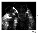
図3は、TEE超音波画像を示しており、図から、その開いた位置にある前側の僧帽弁弁尖34が、医療インプラントが配置されうる左心室流出路36に少なくとも部分的に延在することが分かる。従って、本発明に関して、左心室流出路36はターゲットインプラント領域38として示され、前側の僧帽弁弁尖34は、これが図4に概略的に示されるように、心臓インプラント42と干渉しうる局所的に隣接する領域40として示される。
FIG. 3 shows a TEE ultrasound image from which an anterior mitral valve leaflet 34 in its open position extends at least partially into the left ventricular outflow tract 36 where a medical implant can be placed. I understand that Thus, with respect to the present invention, the left ventricular outflow tract 36 is shown as the target implant region 38 and the anterior mitral valve leaflet 34 is a local area that can interfere with the
セグメント化ステップにおいて、少なくともターゲットインプラント領域38及び局所的に隣接する領域40が、左心室流出路36及び前側の僧帽弁弁尖34の動態を決定するために、マルチステップアプローチにおいてセグメント化される。ここで用いられるモデルは、平均形状を有する三角形表面モデルとして表現される。最初に、心臓位置は、適応された一般化ハフ変換を使用して位置付けられる。次に、それは、検出された境界(外部エネルギーEext)までの距離を最小にするアフィン変換Tのパラメータを決定することによって、反復的に洗練される。最後に、変形可能な適応化の複数の繰り返しが実施され、これは、画像境界(Eext)への引張と平均形状保全(Eint)の間でバランスされる。このような境界検出技法の詳細は、前述のEcabert, O.他の学術論文及びPeters, J. et al.: "Optimizing boundary detection via simulated search with applications to multi-modal heart segmentation", Medical Image Analysis 14(1) (2010) 70の示されており、その内容は、参照によって本願明細書に盛り込まれるものとする。
In the segmentation step, at least the target implant region 38 and the locally
TAVI計画の図示される例については、左心室、左心房、上行大動脈、及び大動脈及び僧帽弁の心内膜表面を含む左心の三角形表面モデルを使用すれば十分である。 For the illustrated example of a TAVI plan, it is sufficient to use a triangular surface model of the left heart that includes the left ventricle, left atrium, ascending aorta, and the endocardial surface of the aorta and the mitral valve.
平均形状
![]()

![]()
しかしながら、これらのモードは、PCAから計算される必要がなく、各々の心臓弁について開いた状態及び閉じた状態の間の線形補間として計算されることができる。 However, these modes do not have to be calculated from PCA, but can be calculated as linear interpolation between the open and closed states for each heart valve.
係数pmは、各々の心臓弁の現在状態を記述する。個々の弁の外側のすべての頂点について、φmのベクトルの要素はゼロであり、ゆえに、残りのモデルの形状に影響を与えない。 Coefficient p m describes the current state of each of the heart valve. For all vertices outside the individual valve, the elements of the vector of φ m are zero and therefore do not affect the shape of the rest of the model.
適応プロセスは、以下の通りに実施される:一般化ハフ変換の後、半分開いた弁を有する平均モデルは、大域的剛体変換Tを評価するために使用される。このステップにおいて、弁の動態は、評価される必要はない。次に、係数pmは、変形可能な適応の間に最適化される。形状抑制エネルギーEintの式は、以下のように与えられる:
ここで、Vは、モデル内の頂点の数であり、N(i)は、i番目の頂点の近傍の頂点であり、vi/jは、変形されたメッシュの頂点位置であり、mi/jは、モデル内の頂点位置である。 Where V is the number of vertices in the model, N (i) is the vertex near the i-th vertex, v i / j is the vertex position of the deformed mesh, and mi / J is the vertex position in the model.
更に、ペナルティ項が、反生理的なモード係数pmを回避するために、重みβと共に全エネルギーに加えられることができる。 Furthermore, the penalty term, in order to avoid anti-physiological mode coefficients p m, may be added to the total energy with weights beta.
特定の患者からのデータを解析するために、受け取られた画像データのすべての心臓位相が、上述のモデル及びフレームワークを使用してセグメント化される。このために、第1の心臓位相がセグメント化され、結果は、次の心臓位相のための初期化として使用される。変形可能な適応が、初期化として個々の以前の結果を用いて、次の心臓位相の間に実施されるだけである。 In order to analyze data from a particular patient, all cardiac phases of the received image data are segmented using the model and framework described above. For this purpose, the first cardiac phase is segmented and the result is used as an initialization for the next cardiac phase. A deformable adaptation is only performed during the next cardiac phase, using the individual previous results as initialization.
大域的運動又は他の変位を補償するために、1つの時間連続の画像シーケンスからセグメント化されたすべてのメッシュが、好適には、収縮末期状態におけるメッシュに位置合わせされる。最も好適には、各フレームで検出される大動脈弁環ポイントが、ターゲットインプラント領域38に対するすべての心臓運動を得るために、互いに位置合わせされる。 To compensate for global motion or other displacements, all meshes segmented from one time-continuous image sequence are preferably aligned with the mesh in the end systole state. Most preferably, the aortic annulus points detected in each frame are aligned with each other to obtain all heart motion relative to the target implant region 38.
上述のセグメント化の結果として、ターゲットインプラント領域38(例えば左心室流出路36)に局所的に隣接する領域40(例えば前側の僧帽弁弁尖34)の動きの軌道が、それぞれ異なる複数の表面ポイントについて決定される。これは、前側の僧帽弁弁尖34の運動をかなり正確に動画化することを可能にする。 As a result of the segmentation described above, a plurality of surfaces with different trajectories of movement of a region 40 (eg, anterior mitral valve leaflet 34) that is locally adjacent to a target implant region 38 (eg, left ventricular outflow tract 36). Determined for points. This allows the movement of the anterior mitral valve leaflet 34 to be animated fairly accurately.
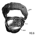
受け取られた軌道の運動解析を簡略化するために、座標系が、セグメント化ユニット22によって好適に導入される。TAVI計画の具体的な例において、この座標系は、ターゲットインプラント領域38(左心室流出路36)内に好適に配置され、この場合、z軸が、ターゲットインプラント領域38が実質的に延びる長手軸(図5参照)に沿って配置される。ターゲットインプラント領域38の横断面は、楕円形リング44としてモデル化されることができ、x軸は、この楕円44の主軸に沿ってアラインされ、y軸は、楕円の副軸に沿ってアラインされる(図6参照)。この座標系の起点は、z軸に沿って、大動脈リング平面46の方へシフトされることができる。このように、すべてのz距離は、大動脈リング平面46を基準として参照される。
A coordinate system is preferably introduced by the
3.第3の方法ステップS14(「インプラントシミュレーション」)
シミュレーションユニット24によって実施されるインプラントシミュレーションステップにおいて、心臓インプラント42及びターゲットインプラント領域38内でのその位置がシミュレートされる。これは、好適には、受け取られた3D画像シーケンスの各フレームにおいて行われる。心臓インプラント42は、例えばセグメント化ユニット22において決定されたターゲットインプラント領域38の横断面である、楕円形横断面を有する仮想モデルによってシミュレートされることができる。所与の例において、セグメント化ステップS12において決定された楕円形リング44は、z軸に沿って延在することができ、かかるz軸に沿って、ターゲットインプラント領域38が実質的に延在する。代替として、心臓インプラント42(より現実的な態様のステントの形状に似ている)の他の仮想3Dモデルが、シミュレーションにおいて用いられることができる。入力インタフェース30によって、ユーザは更に、シミュレートされた心臓インプラント42のサイズ、形状及び/又は位置を手動で変えることができる。
3. Third method step S14 ("implant simulation")
In an implant simulation step performed by the
4.第4の方法ステップS16(「衝突検出」)
衝突評価ユニット26によって実施される衝突検出ステップにおいて、セグメント化された局所的に隣接する領域40と、シミュレートされた心臓インプラント42との重なりが計算される。所与の例において、前側の僧帽弁弁尖34が仮想心臓インプラント42にどの程度突き出るかが計算される。この計算された重なりは、図4に概略的に示され、参照数字46によって示されている。これは、好適には、3D画像シーケンスの各フレームごとに行われる。
4). Fourth method step S16 ("collision detection")
In the collision detection step performed by the
前側の僧帽弁弁尖34上のいくつかのセグメント化されたポイントの軌道が、規定された座標系に関して、セグメント化され位置合わせされたメッシュ(セグメント化ステップS12を参照)から決定されることができる。次のステップにおいて、衝突評価ユニット26は、好適には、ターゲットインプラント領域38の長手軸の関数として各フレームの重なり情報を受け取るために、複数の3D心臓画像14、14'の各々において、z軸に沿った複数の異なる空間ロケーションにおける重なりを決定する。
The trajectories of several segmented points on the anterior mitral valve leaflet 34 are determined from the segmented and aligned mesh (see segmentation step S12) with respect to a defined coordinate system Can do. In the next step, the
更に、衝突評価ユニット26は、3D画像シーケンスの各フレームにおいて個々の空間ロケーションで生じる重なり46を互いに比較することによって、複数の異なる空間ロケーションの各々について最大重なり46を決定するように構成される。このように、z軸上の各位置における最大重なりの程度が決定される。計算を容易にするために、衝突評価ユニット26は、好適には、z軸上の特定の特徴的なポイントについて(例えば2.5mmのステップ幅で)最大重なりを評価するだけである。
Further, the
上述の衝突計算/評価は、セグメント化S12において見つけられた前側の僧帽弁弁尖34のすべてのセグメント化され位置合わせされたポイントを組み合わせてポイントクラウドにすることによって、実施されることができる。このポイントクラウドのポイントは、規定されたステップ幅に従って、グループにマージされることができる。ポイントのグループごとに、最大重なりが、z軸上の異なる位置における最大重なりを得るために計算されることができる。 The collision calculation / evaluation described above can be performed by combining all the segmented and aligned points of the anterior mitral valve leaflet 34 found in segmentation S12 into a point cloud. . The points of this point cloud can be merged into groups according to a defined step size. For each group of points, the maximum overlap can be calculated to obtain the maximum overlap at different locations on the z-axis.
5.第5の方法ステップS18(「フィードバック」)
最後に、計算された重なり46に関するフィードバック情報が、フィードバックユニット28を通じて与えられることができる。このようなフィードバックの1つの例が図7に示される。
5. Fifth method step S18 (“Feedback”)
Finally, feedback information regarding the
図7は、z軸に沿った異なる空間ロケーションの関数として、最大重なり46を示すグラフィック表現48を示す。これらの最大重なり値は、相対的な最大値であり、これは、心臓周期の間、特定の位置に生じた最大の重なり値を意味することが理解されるべきである。各々の最大重なりは、各フレームにおいて個々の位置の重なりを評価し及びそれを他のフレームの当該位置に現れる値と比較することによって、得られる。
FIG. 7 shows a
グラフィック表現48は、18人の異なる患者の3D TEEデータセットから算出されたいくつかの重なり曲線を示す。各々の曲線は、大動脈リング平面からの距離の関数として、僧帽弁弁尖移動と仮想心臓インプラント42の間の最大重なりを示す。従って、絶対的な最大重なり(各曲線において最大重なりを有するポイント)は、患者の間で大幅に異なっており、絶対的な最大値の程度が異なるだけでなく、絶対的な最大値が現れる位置も異なる。最小の重なりを有する患者(参照数字50によって示される)は、約4.7mmの絶対的な最大重なりを有するが、最大の重なりを有する患者(参照数字52によって示される)は、約16.6mmの絶対的な最大重なりを有する。更に、所与のインプラント深さにおける相対的な最大重なりも大きく異なる。商業的に入手可能なインプラントの下方リムの典型的な深さである12.5−15mmのインプラント深さにおいて、重なりは、約2.6乃至13.4mmの間で変化する。
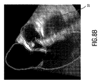
これらの個体差は、図8A及び図8Bに示される例示的なセグメント化からも理解されることができる。両方の画像は、心臓周期の間の、僧帽弁が開いている時間ポイントにおける2人の異なる患者の心臓を示す。互いに2つの画像を比較することによって、前側の僧帽弁弁尖と左心室流出路延長部との間の重なりが非常に異なっていることが分かる。図8Aにおいて、重なりは、約8mm程度であり、最大重なりは、大動脈リング平面からかなり遠くに位置する。図8Bにおいて、最大重なりは、15mmを超えており、大動脈リング平面のかなり近くに位置する。 These individual differences can also be understood from the exemplary segmentation shown in FIGS. 8A and 8B. Both images show the hearts of two different patients at the time point where the mitral valve is open during the cardiac cycle. By comparing the two images to each other, it can be seen that the overlap between the anterior mitral valve leaflet and the left ventricular outflow tract extension is very different. In FIG. 8A, the overlap is on the order of about 8 mm, and the maximum overlap is located far away from the aortic ring plane. In FIG. 8B, the maximum overlap is greater than 15 mm and is located very close to the aortic ring plane.
所与の結果は、本発明によるシステム及び方法が心臓インプラントの植え込みを計画するための強力なツールであることを示している。図7に示されるグラフィック表現は、医師にとってのリスク評価を大幅に簡略化し、更に、医師が、正確な形状に作られ及びサイズ設計された心臓インプラントを選択することを可能にする。 The given results show that the system and method according to the present invention is a powerful tool for planning the implantation of cardiac implants. The graphical representation shown in FIG. 7 greatly simplifies the risk assessment for the physician and further allows the physician to select a heart implant that is made and sized in the correct shape.
要するに、提示された方法は、外科手術の前に、又は、外科手術中に、心臓インプラントの植え込みを正確に計画することを可能にする。方法は、一連の医療3D画像を動的にセグメント化し、動的な心臓モデルと仮想インプラントモデルとの重なりを計算する又は評価することを可能にする。上述の記述は主にTAVIに焦点を合わせたものであるが、提示された方法は、心臓の他の領域における他の心臓インプラントを計画するために使用されることもできる。更に、本発明は、医療画像の特定のタイプ(MR、CT、超音波)に制限されず、さまざまな医療イメージング技法のために実現されることができる。 In short, the presented method allows for the precise planning of the implantation of a cardiac implant before or during a surgical procedure. The method allows to dynamically segment a series of medical 3D images and to calculate or evaluate the overlap between the dynamic heart model and the virtual implant model. Although the above description is primarily focused on TAVI, the presented method can also be used to plan other cardiac implants in other regions of the heart. Furthermore, the present invention is not limited to a particular type of medical image (MR, CT, ultrasound) and can be implemented for various medical imaging techniques.
本発明は、図面及び上述の記述において詳しく図示され記述されているが、このような図示及び記述は、制限的でなく、説明的又は例示的なものとして考えられるべきである。本発明は、開示される実施形態に制限されない。開示された実施形態に対する他の変化は、図面、開示及び添付の請求項の検討から、請求項に記載の本発明を実施する際に当業者によって理解され実現されることができる。 While the invention has been illustrated and described in detail in the drawings and foregoing description, such illustration and description are to be considered illustrative or exemplary and not restrictive; The invention is not limited to the disclosed embodiments. Other changes to the disclosed embodiments can be understood and realized by those skilled in the art in practicing the claimed invention, from a study of the drawings, the disclosure, and the appended claims.
請求項において、「含む、有する」という語は、他の構成要素を除外せず、不定冠詞品「a」又は「an」は、複数性を除外しない。単一の構成要素又は他のユニットは、請求項に列挙されるいくつかのアイテムの機能を果たすことができる。特定の手段が相互に異なる従属請求項に列挙されているという単なる事実は、これらの手段の組み合わせが有利に使用されることができないことを示さない。 In the claims, the word “comprising” does not exclude other elements, and the indefinite article “a” or “an” does not exclude a plurality. A single component or other unit may fulfill the functions of several items recited in the claims. The mere fact that certain measures are recited in mutually different dependent claims does not indicate that a combination of these measured cannot be used to advantage.
コンピュータプログラムは、例えば他のハードウェアと共に又はその一部として供給される光学記憶媒体又はソリッドステート媒体のような、適切な媒体に記憶され/配布されることができるが、インターネット又は他のワイヤード又はワイヤレスの通信システムを介してのように、他の形式で配布されることができる。 The computer program can be stored / distributed on a suitable medium, such as an optical storage medium or solid state medium supplied with or as part of other hardware, for example on the Internet or other wired or It can be distributed in other formats, such as via a wireless communication system.
請求項におけるいかなる参照符号も、本発明の範囲を制限するものとして解釈されるべきでない。 Any reference signs in the claims should not be construed as limiting the scope of the invention.
Claims (20)
心臓周期の最中、心臓の個々の異なる状態を示す複数の3D心臓画像を受け取るインタフェースと、
前記インタフェースと通信するプロセッサと、
を有し、前記プロセッサが、
前記インタフェースを通じて、前記複数の3D心臓画像を受け取る処理と、
前記複数の3D心臓画像において、ターゲットインプラント領域及び前記心臓インプラントと干渉しうる局所的に隣接する領域をセグメント化する処理であって、前記ターゲットインプラント領域が左心室流出路の一部であり、前記局所的に隣接する領域が僧帽弁の一部である、処理と、
前記複数の3D心臓画像のうち少なくとも2つにおいて、前記ターゲットインプラント領域への前記心臓インプラントの植え込みをシミュレートする処理と、
前記複数の3D心臓画像のうちの少なくとも2つにおいて、前記セグメント化された局所的に隣接する領域と、前記シミュレートされた心臓インプラントとの重なりを評価する処理と、
前記複数の3D心臓画像の各々において、前記ターゲットインプラント領域の長手軸に沿った複数の異なる空間ロケーションにおける前記重なりを決定する処理と、
前記評価された重なりを示すフィードバック情報を、フィードバックユニットを通じてユーザに提供する処理と、
を実行するようプログラムされた医療イメージングシステム。 A medical imaging system for planning implantation of a cardiac implant,
An interface for receiving a plurality of 3D heart images showing individual different states of the heart during a cardiac cycle;
A processor in communication with the interface;
And the processor is
Receiving the plurality of 3D heart images through the interface;
Segmenting a target implant region and a locally adjacent region that can interfere with the cardiac implant in the plurality of 3D heart images, the target implant region being part of a left ventricular outflow tract, A locally adjacent region is part of the mitral valve; and
Simulating implantation of the cardiac implant in the target implant region in at least two of the plurality of 3D heart images;
Evaluating an overlap between the segmented locally adjacent region and the simulated cardiac implant in at least two of the plurality of 3D heart images;
In each of the plurality of 3D cardiac imaging, a process to decide the overlapping said at a plurality of different spatial locations along the longitudinal axis of the target implant region,
Providing feedback information indicating the evaluated overlap to a user through a feedback unit;
A medical imaging system programmed to perform.
心臓周期の最中、心臓の個々の異なる状態を示す複数の3D心臓画像を受け取るインタフェースと、
前記インタフェースと通信するプロセッサと、
を有し、前記プロセッサが、
前記インタフェースを通じて、前記複数の3D心臓画像を受け取る処理と、
前記複数の3D心臓画像において、ターゲットインプラント領域及び前記心臓インプラントと干渉しうる局所的に隣接する領域をセグメント化する処理であって、前記ターゲットインプラント領域が右心室流出路の一部であり、前記局所的に隣接する領域が三尖弁の一部である、処理と、
前記複数の3D心臓画像のうち少なくとも2つにおいて、前記ターゲットインプラント領域への前記心臓インプラントの植え込みをシミュレートする処理と、
前記複数の3D心臓画像のうち少なくとも2つにおいて、前記セグメント化された局所的に隣接する領域と、前記シミュレートされた心臓インプラントとの重なりを評価する処理と、
前記複数の3D心臓画像の各々において、前記ターゲットインプラント領域の長手軸に沿った複数の異なる空間ロケーションにおける前記重なりを決定する処理と、
前記評価された重なりを示すフィードバック情報を、フィードバックユニットを通じてユーザに提供する処理と、
を実行する医療イメージングシステム。 A medical imaging system for planning implantation of a cardiac implant,
An interface for receiving a plurality of 3D heart images showing individual different states of the heart during a cardiac cycle;
A processor in communication with the interface;
And the processor is
Receiving the plurality of 3D heart images through the interface;
Segmenting a target implant region and a locally adjacent region that can interfere with the cardiac implant in the plurality of 3D heart images, the target implant region being part of a right ventricular outflow tract, Processing where the locally adjacent region is part of a tricuspid valve; and
Simulating implantation of the cardiac implant in the target implant region in at least two of the plurality of 3D heart images;
Evaluating an overlap between the segmented locally adjacent region and the simulated cardiac implant in at least two of the plurality of 3D heart images;
In each of the plurality of 3D cardiac imaging, a process to decide the overlapping said at a plurality of different spatial locations along the longitudinal axis of the target implant region,
Providing feedback information indicating the evaluated overlap to a user through a feedback unit;
Performing medical imaging system.
心臓周期の最中、心臓の個々の異なる状態を示す複数の3D心臓画像を受け取るステップと、
前記複数の3D心臓画像において、ターゲットインプラント領域及び心臓インプラントと干渉しうる局所的に隣接する領域をセグメント化するステップであって、前記ターゲットインプラント領域が左心室流出量路の一部であり、前記局所的に隣接する領域が僧帽弁の一部である、ステップと、
前記複数の3D心臓画像のうち少なくとも2つにおいて、前記ターゲットインプラント領域への前記心臓インプラントの植え込みをシミュレートするステップと、
前記複数の3D心臓画像のうち少なくとも2つにおいて、前記セグメント化された局所的に隣接する領域と、前記シミュレートされた心臓インプラントとの重なりを評価するステップと、
前記3D心臓画像内の前記ターゲットインプラント領域の長手軸に沿った複数の異なる空間ロケーションにおける前記重なりを、空間ロケーションごとに前記3D心臓画像間で比較することによって、前記ターゲットインプラント領域の前記長手軸に沿った最大重なりを、前記長手軸に沿った空間ロケーションの関数として決定するステップと、
前記評価された重なりを示すフィードバック情報をユーザに提供するステップと、
の各ステップを実行する方法。 A method of planning implantation of a cardiac implant, wherein a processor
Receiving a plurality of 3D heart images indicative of individual different states of the heart during a cardiac cycle;
In the plurality of 3D cardiac imaging, comprising the steps of segmenting locally adjacent regions may interfere with the target implant region及beauty heart implants, the target implant region be part of the left ventricle outflow path The locally adjacent region is part of a mitral valve;
Simulating implantation of the cardiac implant in the target implant region in at least two of the plurality of 3D heart images;
Assessing an overlap between the segmented locally adjacent region and the simulated cardiac implant in at least two of the plurality of 3D heart images;
The overlapping at a plurality of different spatial locations along the longitudinal axis of the target implant region in the 3D cardiac imaging, by comparing between the 3D cardiac images for each spatial location, the longitudinal axis of the front Symbol Target implant region Determining a maximum overlap along as a function of spatial location along the longitudinal axis ;
Providing feedback information to the user indicating the estimated overlap;
To perform each step .
心臓周期の最中、心臓の個々の異なる状態を示す複数の3D心臓画像を受け取るステップと、
前記複数の3D心臓画像において、ターゲットインプラント領域及び心臓インプラントと干渉しうる局所的に隣接する領域をセグメント化するステップであって、前記ターゲットインプラント領域が右心室流出路の一部であり、前記局所的に隣接する領域が三尖弁の一部である、ステップと、
前記複数の3D心臓画像のうち少なくとも2つにおいて、前記ターゲットインプラント領域への前記心臓インプラントの植え込みをシミュレートするステップと、
前記複数の3D心臓画像のうち少なくとも2つにおいて、前記セグメント化された局所的に隣接する領域と前記シミュレートされた心臓インプラントとの重なりを評価するステップと、
前記3D心臓画像内の前記ターゲットインプラント領域の長手軸に沿った複数の異なる空間ロケーションにおける前記重なりを、空間ロケーションごとに前記3D心臓画像間で比較することによって、前記ターゲットインプラント領域の前記長手軸に沿った最大重なりを、前記長手軸に沿った空間ロケーションの関数として決定するステップと、
前記評価された重なりを示すフィードバック情報をユーザに提供するステップと、
の各ステップを実行する方法。 A method of planning implantation of a cardiac implant, wherein a processor
Receiving a plurality of 3D heart images indicative of individual different states of the heart during a cardiac cycle;
In the plurality of 3D cardiac imaging, comprising the steps of segmenting locally adjacent regions may interfere with the target implant region及beauty heart implants, the target implant region is part of the right ventricular outflow tract, The locally adjacent region is part of a tricuspid valve; and
Simulating implantation of the cardiac implant in the target implant region in at least two of the plurality of 3D heart images;
Evaluating an overlap between the segmented locally adjacent region and the simulated cardiac implant in at least two of the plurality of 3D heart images;
The overlapping at a plurality of different spatial locations along the longitudinal axis of the target implant region in the 3D cardiac imaging, by comparing between the 3D cardiac images for each spatial location, the longitudinal axis of the front Symbol Target implant region Determining a maximum overlap along as a function of spatial location along the longitudinal axis ;
Providing feedback information to the user indicating the estimated overlap;
To perform each step .
前記複数の3D心臓画像において、ターゲットインプラント領域及び心臓インプラントと干渉しうる局所的に隣接する領域をセグメント化するステップと、
前記複数の3D心臓画像のうち少なくとも2つにおいて、前記ターゲットインプラント領域への前記心臓インプラントの植え込みをシミュレートするステップと、
前記複数の3D心臓画像のうちの前記少なくとも2つにおいて、前記ターゲットインプラント領域の長手軸に沿った複数の異なる空間ロケーションにおける、前記セグメント化された局所的に隣接する領域と、前記シミュレートされた心臓インプラントとの重なりを評価するステップと、
前記評価された重なりを示すフィードバック情報をユーザに提供するステップと、
をプロセッサに実行させるコンピュータプログラム。 Receiving a plurality of 3D heart images indicative of individual different states of the heart during a cardiac cycle;
In the plurality of 3D cardiac imaging, comprising the steps of: segmenting the locally adjacent regions may interfere with the target implant region及beauty heart implant,
Simulating implantation of the cardiac implant in the target implant region in at least two of the plurality of 3D heart images;
In at least two of the plurality of 3D cardiac imaging, at a plurality of different spatial locations along the longitudinal axis of the target implant region, and locally adjacent regions which are the segmented, it is the simulated and a step to evaluate the overlap of the heart implant,
Providing feedback information to the user indicating the estimated overlap;
A computer program that causes a processor to execute.
Applications Claiming Priority (3)
| Application Number | Priority Date | Filing Date | Title |
|---|---|---|---|
| EP13170984.2 | 2013-06-07 | ||
| EP13170984 | 2013-06-07 | ||
| PCT/EP2014/061254 WO2014195237A1 (en) | 2013-06-07 | 2014-05-30 | Planning an implantation of a cardiac implant |
Publications (3)
| Publication Number | Publication Date |
|---|---|
| JP2016526954A JP2016526954A (en) | 2016-09-08 |
| JP2016526954A5 JP2016526954A5 (en) | 2018-03-15 |
| JP6382304B2 true JP6382304B2 (en) | 2018-08-29 |
Family
ID=48792951
Family Applications (1)
| Application Number | Title | Priority Date | Filing Date |
|---|---|---|---|
| JP2016517250A Active JP6382304B2 (en) | 2013-06-07 | 2014-05-30 | Medical imaging system |
Country Status (5)
| Country | Link |
|---|---|
| US (2) | US9956046B2 (en) |
| EP (1) | EP3005310B1 (en) |
| JP (1) | JP6382304B2 (en) |
| CN (1) | CN105264573B (en) |
| WO (1) | WO2014195237A1 (en) |
Families Citing this family (12)
| Publication number | Priority date | Publication date | Assignee | Title |
|---|---|---|---|---|
| EP2797657B1 (en) * | 2011-12-30 | 2019-03-13 | St. Jude Medical, Atrial Fibrillation Division, Inc. | System and method for detection and avoidance of collisions of robotically-controlled medical devices |
| CN103312727A (en) * | 2012-03-06 | 2013-09-18 | 创业软件股份有限公司 | Method for cloud computing deployment in the field of cooperative services of regional medical care |
| WO2015179543A1 (en) * | 2014-05-20 | 2015-11-26 | Piazza Nicolo | System and method for valve quantification |
| JP6411073B2 (en) * | 2014-06-02 | 2018-10-24 | キヤノンメディカルシステムズ株式会社 | Medical image processing apparatus and medical image processing method |
| EP3267897B1 (en) | 2015-03-10 | 2023-08-16 | Koninklijke Philips N.V. | Ultrasonic diagnosis of cardiac performance using heart model chamber segmentation with user control |
| US9931790B2 (en) * | 2015-04-16 | 2018-04-03 | Siemens Healthcare Gmbh | Method and system for advanced transcatheter aortic valve implantation planning |
| CN110494923B (en) | 2017-03-31 | 2023-12-08 | 皇家飞利浦有限公司 | Simulation of the effects on coronary flow and pressure caused by Transcatheter Aortic Valve Implantation (TAVI) |
| EP3422226A1 (en) * | 2017-06-29 | 2019-01-02 | Koninklijke Philips N.V. | Device and method for predicting an unfolded state of a foldable implant in cardiovascular tissue |
| CN108230431B (en) * | 2018-01-24 | 2022-07-12 | 深圳市云之梦科技有限公司 | Human body action animation generation method and system of two-dimensional virtual image |
| EP3542757A1 (en) * | 2018-03-23 | 2019-09-25 | FEops NV | Method and system for patient-specific virtual percutaneous structural heart intervention |
| EP3944252A1 (en) * | 2020-07-21 | 2022-01-26 | Virtonomy GmbH | System for automatically evaluating virtual patient fitting of medical devices |
| CN113796992A (en) * | 2021-09-26 | 2021-12-17 | 上海市同济医院 | Automatic valve stent conveying system based on image segmentation |
Family Cites Families (14)
| Publication number | Priority date | Publication date | Assignee | Title |
|---|---|---|---|---|
| US7536041B2 (en) | 2003-06-13 | 2009-05-19 | Koninklijke Philips Electronics N.V. | 3D image segmentation |
| CN100493460C (en) * | 2007-04-12 | 2009-06-03 | 中国人民解放军第三军医大学第一附属医院 | Dummy echocardiography system via gullet |
| DE102007039207A1 (en) * | 2007-08-20 | 2009-02-26 | Siemens Ag | Object collision detection method for dimensioning of medical y-stent utilized during endcoscopic procedure in patient, involves determining whether point of frame lying in limitation capacity of another frame is lying within closed surface |
| US7970719B2 (en) * | 2008-06-06 | 2011-06-28 | Siemens Aktiengesellschaft | Method and simulation device for structurally individualized simulation of the introduction of a wall support element into a section of a tubular structure |
| US9715637B2 (en) | 2009-03-18 | 2017-07-25 | Siemens Healthcare Gmbh | Method and system for automatic aorta segmentation |
| WO2010129193A1 (en) * | 2009-05-08 | 2010-11-11 | Koninklijke Philips Electronics, N.V. | Ultrasonic planning and guidance of implantable medical devices |
| WO2010150147A1 (en) * | 2009-06-24 | 2010-12-29 | Koninklijke Philips Electronics N. V. | Spatial and shape characterization of an implanted device within an object |
| US10719986B2 (en) * | 2009-12-22 | 2020-07-21 | Siemens Healthcare Gmbh | Method and system for virtual percutaneous valve implantation |
| WO2011132131A1 (en) | 2010-04-21 | 2011-10-27 | Koninklijke Philips Electronics N.V. | Method for determining a physical property of an object, system, computer readable medium and program element |
| US8620050B2 (en) | 2010-09-23 | 2013-12-31 | Siemens Aktiengesellschaft | System and method for 2-D/3-D registration between 3-D volume and 2-D angiography |
| US9058664B2 (en) | 2011-09-07 | 2015-06-16 | Siemens Aktiengesellschaft | 2D-2D fusion for interventional guidance in trans-catheter aortic valve implantation |
| CA2856549A1 (en) * | 2011-12-01 | 2013-06-06 | Neochord, Inc. | Surgical navigation for repair of heart valve leaflets |
| US10789772B2 (en) * | 2012-05-16 | 2020-09-29 | Feops Nv | Pre-operative simulation of trans-catheter valve implantation |
| JP2016501636A (en) * | 2012-12-21 | 2016-01-21 | ヴォルカノ コーポレイションVolcano Corporation | Adaptive interface for medical imaging systems |
-
2014
- 2014-05-30 EP EP14727498.9A patent/EP3005310B1/en active Active
- 2014-05-30 US US14/895,604 patent/US9956046B2/en active Active
- 2014-05-30 CN CN201480032065.2A patent/CN105264573B/en active Active
- 2014-05-30 JP JP2016517250A patent/JP6382304B2/en active Active
- 2014-05-30 WO PCT/EP2014/061254 patent/WO2014195237A1/en active Application Filing
-
2018
- 2018-04-04 US US15/944,919 patent/US10695131B2/en active Active
Also Published As
| Publication number | Publication date |
|---|---|
| US20180289424A1 (en) | 2018-10-11 |
| US10695131B2 (en) | 2020-06-30 |
| EP3005310A1 (en) | 2016-04-13 |
| JP2016526954A (en) | 2016-09-08 |
| US20160128786A1 (en) | 2016-05-12 |
| WO2014195237A1 (en) | 2014-12-11 |
| US9956046B2 (en) | 2018-05-01 |
| EP3005310B1 (en) | 2021-01-13 |
| CN105264573A (en) | 2016-01-20 |
| CN105264573B (en) | 2019-07-02 |
Similar Documents
| Publication | Publication Date | Title |
|---|---|---|
| JP6382304B2 (en) | Medical imaging system | |
| US11069136B2 (en) | Pre-operative simulation of trans-catheter valve implantation | |
| US10719986B2 (en) | Method and system for virtual percutaneous valve implantation | |
| US8682626B2 (en) | Method and system for comprehensive patient-specific modeling of the heart | |
| EP3081161B1 (en) | Method and system for advanced transcatheter aortic valve implantation planning | |
| US11051885B2 (en) | Method and system for determining a risk of hemodynamic compromise after cardiac intervention | |
| EP3146507B1 (en) | System and method for valve quantification | |
| US8009887B2 (en) | Method and system for automatic quantification of aortic valve function from 4D computed tomography data using a physiological model | |
| JP5868052B2 (en) | Comprehensive patient-specific heart modeling method and system | |
| CN106716488B (en) | Analysis of aortic valve calcification | |
| US9730609B2 (en) | Method and system for aortic valve calcification evaluation | |
| US20110052026A1 (en) | Method and Apparatus for Determining Angulation of C-Arm Image Acquisition System for Aortic Valve Implantation | |
| CN112040908A (en) | Patient-specific virtual percutaneous structural cardiac intervention methods and systems | |
| EP3555846B1 (en) | Stress prediction and stress assessment for device insertion into a deformable object | |
| US20220273369A1 (en) | Method and system for determining a risk of hemodynamic compromise after cardiac intervention | |
| WO2014064066A1 (en) | Simulation of objects in an atlas and registration of patient data containing a specific structure to atlas data | |
| CN110494923B (en) | Simulation of the effects on coronary flow and pressure caused by Transcatheter Aortic Valve Implantation (TAVI) | |
| CA3217879A1 (en) | Systems and methods for reconstructing implantable device geometry from patient-specific imaging scans | |
| Ionasec et al. | Patient-specific modeling of the heart: applications to cardiovascular disease management | |
| JP2024516952A (en) | Method for modeling a heart valve - Patents.com | |
| Book | Modeling of Aortic Valve Anatomic Geometry from Clinical Multi Detector-Row Computed Tomography Images |
Legal Events
| Date | Code | Title | Description |
|---|---|---|---|
| RD04 | Notification of resignation of power of attorney |
Free format text: JAPANESE INTERMEDIATE CODE: A7424 Effective date: 20170214 |
|
| A621 | Written request for application examination |
Free format text: JAPANESE INTERMEDIATE CODE: A621 Effective date: 20170519 |
|
| A521 | Request for written amendment filed |
Free format text: JAPANESE INTERMEDIATE CODE: A523 Effective date: 20180205 |
|
| A871 | Explanation of circumstances concerning accelerated examination |
Free format text: JAPANESE INTERMEDIATE CODE: A871 Effective date: 20180205 |
|
| A975 | Report on accelerated examination |
Free format text: JAPANESE INTERMEDIATE CODE: A971005 Effective date: 20180313 |
|
| A977 | Report on retrieval |
Free format text: JAPANESE INTERMEDIATE CODE: A971007 Effective date: 20180323 |
|
| A131 | Notification of reasons for refusal |
Free format text: JAPANESE INTERMEDIATE CODE: A131 Effective date: 20180412 |
|
| A521 | Request for written amendment filed |
Free format text: JAPANESE INTERMEDIATE CODE: A523 Effective date: 20180711 |
|
| TRDD | Decision of grant or rejection written | ||
| A01 | Written decision to grant a patent or to grant a registration (utility model) |
Free format text: JAPANESE INTERMEDIATE CODE: A01 Effective date: 20180726 |
|
| A61 | First payment of annual fees (during grant procedure) |
Free format text: JAPANESE INTERMEDIATE CODE: A61 Effective date: 20180801 |
|
| R150 | Certificate of patent or registration of utility model |
Ref document number: 6382304 Country of ref document: JP Free format text: JAPANESE INTERMEDIATE CODE: R150 |
|
| R250 | Receipt of annual fees |
Free format text: JAPANESE INTERMEDIATE CODE: R250 |
|
| R250 | Receipt of annual fees |
Free format text: JAPANESE INTERMEDIATE CODE: R250 |
|
| R250 | Receipt of annual fees |
Free format text: JAPANESE INTERMEDIATE CODE: R250 |