EP3003201B1 - Procédé de fabrication d'un attachement orthodontique de remplacement spécifique au patient pour un traitement d'orthopédie maxillaire - Google Patents
Procédé de fabrication d'un attachement orthodontique de remplacement spécifique au patient pour un traitement d'orthopédie maxillaire Download PDFInfo
- Publication number
- EP3003201B1 EP3003201B1 EP14725978.2A EP14725978A EP3003201B1 EP 3003201 B1 EP3003201 B1 EP 3003201B1 EP 14725978 A EP14725978 A EP 14725978A EP 3003201 B1 EP3003201 B1 EP 3003201B1
- Authority
- EP
- European Patent Office
- Prior art keywords
- bracket
- slot
- process according
- tooth
- reference plane
- Prior art date
- Legal status (The legal status is an assumption and is not a legal conclusion. Google has not performed a legal analysis and makes no representation as to the accuracy of the status listed.)
- Not-in-force
Links
- 238000004519 manufacturing process Methods 0.000 title claims description 18
- 238000000034 method Methods 0.000 claims description 40
- 229910052602 gypsum Inorganic materials 0.000 claims description 5
- 239000010440 gypsum Substances 0.000 claims description 5
- 239000000463 material Substances 0.000 claims description 5
- 238000006073 displacement reaction Methods 0.000 claims 1
- 238000005094 computer simulation Methods 0.000 description 17
- 239000011505 plaster Substances 0.000 description 6
- 240000006829 Ficus sundaica Species 0.000 description 3
- 239000000853 adhesive Substances 0.000 description 2
- 230000001070 adhesive effect Effects 0.000 description 2
- 210000004513 dentition Anatomy 0.000 description 2
- 230000036346 tooth eruption Effects 0.000 description 2
- 238000003860 storage Methods 0.000 description 1
- 238000003466 welding Methods 0.000 description 1
Images


Classifications
-
- A—HUMAN NECESSITIES
- A61—MEDICAL OR VETERINARY SCIENCE; HYGIENE
- A61C—DENTISTRY; APPARATUS OR METHODS FOR ORAL OR DENTAL HYGIENE
- A61C7/00—Orthodontics, i.e. obtaining or maintaining the desired position of teeth, e.g. by straightening, evening, regulating, separating, or by correcting malocclusions
- A61C7/002—Orthodontic computer assisted systems
-
- A—HUMAN NECESSITIES
- A61—MEDICAL OR VETERINARY SCIENCE; HYGIENE
- A61C—DENTISTRY; APPARATUS OR METHODS FOR ORAL OR DENTAL HYGIENE
- A61C7/00—Orthodontics, i.e. obtaining or maintaining the desired position of teeth, e.g. by straightening, evening, regulating, separating, or by correcting malocclusions
- A61C7/12—Brackets; Arch wires; Combinations thereof; Accessories therefor
- A61C7/14—Brackets; Fixing brackets to teeth
- A61C7/145—Lingual brackets
-
- A—HUMAN NECESSITIES
- A61—MEDICAL OR VETERINARY SCIENCE; HYGIENE
- A61C—DENTISTRY; APPARATUS OR METHODS FOR ORAL OR DENTAL HYGIENE
- A61C7/00—Orthodontics, i.e. obtaining or maintaining the desired position of teeth, e.g. by straightening, evening, regulating, separating, or by correcting malocclusions
- A61C7/12—Brackets; Arch wires; Combinations thereof; Accessories therefor
- A61C7/14—Brackets; Fixing brackets to teeth
- A61C7/146—Positioning or placement of brackets; Tools therefor
-
- A—HUMAN NECESSITIES
- A61—MEDICAL OR VETERINARY SCIENCE; HYGIENE
- A61C—DENTISTRY; APPARATUS OR METHODS FOR ORAL OR DENTAL HYGIENE
- A61C7/00—Orthodontics, i.e. obtaining or maintaining the desired position of teeth, e.g. by straightening, evening, regulating, separating, or by correcting malocclusions
- A61C7/12—Brackets; Arch wires; Combinations thereof; Accessories therefor
- A61C7/14—Brackets; Fixing brackets to teeth
- A61C7/16—Brackets; Fixing brackets to teeth specially adapted to be cemented to teeth
Definitions
- the invention relates to a method for producing a patient-specific replacement brace for orthodontic treatment, as defined in claim 1.
- brackets are glued to the patient's teeth to be treated and connected by an orthodontic wire.
- the brackets have a pad for connection to the tooth and a bracket body with a slot that receives the wire.
- Brackets are preferably used for the orthodontic treatment, which have an individualized pad, ie the pad of the bracket has an adhesive surface to Connection with the tooth, which is adapted to the respective tooth, so that the bracket can be positively placed on the tooth in a certain position.
- a completely individualized replacement bracket is typically made using the existing gypsum target set-up.
- the method is complicated in particular in that the already existing target set-up generally only has to be sent to a technician's workshop and then the replacement bracket has to be produced there and sent back.
- a disadvantage in the production of a completely individualized replacement bracket is that the method is complex, in particular plaster models of set-ups must be shipped.
- the US 6,015,289 A describes a fully automated method for making brackets after a digital dentition of a patient.
- the WO 01/85047 A2 describes a method and apparatus for positioning a bracket on a tooth using a digital model of the bracket on a digital model of the tooth.
- the US 2009/0017410 A1 describes a method for making brackets according to a digital model of the dentition of a patient, in which digital data is generated in the computer, which represent a customized bracket, with subsequent production of the bracket for the digital data.
- the object of the present invention is therefore to provide a simpler and more cost-effective method for producing a completely individualized replacement bracket.
- step 1a) comprises: 2a) establishing a patient-specific target set-up of the upper or lower jaw of a patient, 2b) determining a slot plane of brackets to be arranged on the teeth to be treated of the upper or lower jaw, 2c) arranging brackets on the 2d) determining the reference plane in the target set-up relative to the slot plane, 2e) removing the brackets from the target set-up, and 2f) electronically storing the target set-up, including the reference plane.
- step 2a) is performed on the basis of a plaster model or on the basis of a virtual model of the upper or lower jaw.
- Step 2d) may be performed before step 2c).
- step 2f) the electronic storage preferably takes place by scanning a physical target set-up or by storing a digital target set-up.
- a lingual or buccal bracket element can be provided as the bracket element in order to produce a lingual bracket or a buccal bracket as a replacement bracket.
- the reference plane in step 1a) can be represented continuously, for example by a line, or intermittently, for example by semicolons on selected teeth.
- the reference plane in step 1a) can be defined identically for all teeth, for example from 18 to 28, or defined for a selected region, for example from 13 to 23, and for the remaining regions a relative shift thereto, for example a depression or raising the reference plane.
- the reference plane can be defined at a fixed distance, for example 3-6 cm, from the slot plane or individually, in particular the reference plane and slot plane are identical.
- the relevant cutout to be determined in step 1c) may comprise at least a portion of the tooth, and preferably the tooth, in particular additionally with a gingival section, optionally additionally at least a portion of the mesially and / or distally adjacent tooth, preferably the entire tooth, in particular in each case additionally with one gingival section, include.
- the marking can be formed as a 2D line or as a 3D body, in particular as a holding section for the tooth.
- the marking may be arranged on the upper or lower edge of a slot in the slot plane or, in the case of a 3D body, on the level of the slot plane, in the latter case the 3D body preferably in the occlusal-gingival direction Thickness corresponding to the height of the slots of the brackets in this direction.
- the holding section is preferably arranged lingually for buccal brackets and preferably buccally for lingual brackets.
- the holding section is preferably connected to a technician holder in step 1g).
- the creation of the model in step 1e) can be done by printing the section with a 3D printer or by means of a CNC machine or a rapid prototyping machine.
- the section in step 1c) can be determined manually or automatically, for example by software.
- the bracket body can be connected to an individualized pad or the standard bracket can be provided with an individualized pad, for example by filling a gap between the tooth and the pad of the standard bracket with a plastic material and curing it.
- a 2D mark can be generated, for example in the form of a line or points, whereby the height of the slide and the angulation of the associated bracket are determined.
- a 3D marking can be generated, for example in the form of a pin, whereby the height of the slit, the angulation and the torque of the associated bracket are determined.
- a 3D marking can be generated with the aid of at least one Bracketrand condition, for example in the form of a pin, whereby the height of the slide, the angulation, the torque and the rotation of the associated bracket are determined.
- the boundary condition is preferably additionally stored in the provided in step 1a) 3D representation of the upper or lower jaw.
- a pin-shaped holding section is preferably produced, which has a side surface which is arranged at the level of the upper or lower edge of the slot of the associated bracket.
- a replacement bracket for any tooth of a jaw acting on the lower jaw.
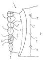
- the procedure is as follows: A gypsum model of his lower jaw is created by a patient, which is to be treated orthodontically. The plaster model is sawn, with the teeth separated. Subsequently, the teeth in a target set-up 11, s. Fig. 1 , arranged to represent the desired treatment result at the end of the treatment.
- brackets 1 are glued to the teeth 5 to be treated.
- lingual brackets 1 are glued to the teeth to be treated, in Fig. 1
- Representative only a bracket 1 on the tooth 46 is shown in dashed lines.
- an orthodontic wire 13 is guided for illustration, also only shown in phantom to exert a force on the teeth 5 via the slots 3S and the brackets 1 in order to move the respective teeth 5 to a desired position.
- all slots 3S of the brackets 1 should lie substantially in one plane, the so-called slot plane 3SE, as in FIG Fig. 1 shown.
- the method according to the invention conforms to some conventional orthodontic treatment planning method: a gypsum target set-up 11 is made, and brackets 1 are glued to the teeth 5, the slots 3S of the brackets being in a plane 3SE.
- a reference plane 9 is now defined.
- the reference plane 9 is in Fig. 1 shown in dashed lines. In the present case, it is defined by three reference plane markings 9M in the form of circles on the plaster model whose respective center points define the reference plane 9. Of the three reference plane markings 9M, one is shown in phantom since it is on the opposite (hidden left) side of the plaster model.
- the reference plane 9 has a fixed distance from the lower edge 3US of the slots 3S of the brackets 1, for example a distance from an interval of 1 to 10 cm, in the present case 3 cm.
- brackets 1 are removed from the target set-up 11, whereby the target set-up 11 of the Fig. 1 without the dashed bracket 1 and the dashed wire 13 results.
- the target set-up 11 thus prepared is now scanned by means of a scanner and the digital computer model of the target set-up 11 is stored in a computer.
- the computer thus has a model of the target set-up 11, which also contains the reference plane 9. Because the computer model contains the reference plane 9 and the relation between slot plane 3S and reference plane 9 is known, the slot model 3S is also defined for the computer model.
- a marking for the lower edge 3US of the slot plane 3SE of the slot 3S of the bracket 1 belonging to the tooth concerned is added to the tooth 5.
- a holding section for the tooth is added to the computer model, shown here by way of example in the form of a pin.
- the holding portion is added to the computer model of the tooth such that an edge of the holding portion is located at the level of the lower edge 3US of the slot 3S.
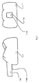
- the computer model of the tooth now results from the representation of the Fig. 2 ,
- Fig. 2 shows two side views of a 3D model of the tooth 5, for which a replacement bracket is to be produced. Only the portion lying above the gingival margin, ie the area of the tooth 5 normally visible to the patient, can be seen from the tooth 5.
- a holding portion 5H in the form of a pin has been added to the tooth 5 as a holder.
- the holding portion 5H has a cross-section substantially the shape of a rectangle, wherein the in Fig. 2 upper side edge of the rectangle is slightly shortened compared to the lower one.
- the holding portion 5H is arranged on the model of the tooth 5 so that the in Fig. 2
- the lower side edge is a marking 5MS for the slot plane, ie this edge is arranged at the level of the lower edge 3US of the slot 3S of the associated bracket 1.
- the computer thus has a model of the tooth 5 for which a replacement bracket is to be produced.
- the model has been widened around the holding section 5H, which has the shape of a pin and whose one edge is arranged at the level of the lower edge 3US of the slot 3S of the associated bracket 1.
- Fig. 2 is produced in the next step as a physical model, for example, printed or manufactured using a 3D printer made of plastic. There is then a plastic model of the tooth 5 which has a height mark for the lower edge 3US of the slot 3S and has a holding portion 5H for holding the physical model.
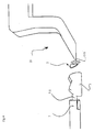
- Fig. 3 shows the front view of a holding section holder 7 of a technician holder, which is adapted to receive the holding portion 5H of the printed tooth 5, and the side view of a slot receiving 15 another technician holder for receiving a slot 3S.
- the slot holder 15 has in the view of Fig. 3 in the vertical direction at the free end, the thickness of a slot-filling orthodontic wire.
- the free end in this way simulates a slot-filling orthodontic wire, ie it forms a wire simulator 15S.
- a slot 3S of a bracket can thus be slid backlash-free on this wire simulator 15S, as described below.
- the underside 15SUS of the wire simulator 15S is at the same height as the bottom edge 3US of a slot 3S of the bracket 1 associated with the tooth 5, as shown in FIG Fig. 3 shown.
- the holding section receptacle 7 has centrally a recess 7A, which is dimensioned in such a way that the holding section 5H of the printed tooth 5 can be inserted in a form-fitting manner.
- the in Fig. 3 lower edge of the recess 7A at the level of the lower edge 3US of the slot 3 of the bracket 5 associated with the tooth 5.
- the bearing surface 7AF of the holding portion receptacle 7, on which the lower surface 15SUS rests, is at the same height as the lower surface of the recess 7A.
- the slot receptacle 15 on the one technician holder and the holding section receptacle 7 on the other technician holder thus each have edges which lie at the level of the lower edge 3US of the slot 3S of the bracket 1 associated with the tooth 5.
- these heights are adjusted to each other as in Fig. 3 shown.
- the underside 15SUS is placed on the illustrated bearing surface 7AF of the holding section receptacle 7 and thus aligned the mutual zero points of the slot receiving 15 and the holding section receptacle 7 to each other, whereby the height adjustment is completed.
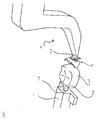
- the printed tooth 5 with its holding section 5H is inserted into the recess 7A of the holding section receptacle 7 and a standard bracket 2 is placed on the wire simulator 15S of the slot receptacle 15, as in FIG Fig. 4 shown. Again Fig. 4 further, the printed tooth 5 and the standard bracket 2 become brought together to put the standard bracket 2 suitable on the printed tooth 5.
- Fig. 5 shows a perspective view of the in Fig. 4 illustrated arrangement.
- Fig. 6 shows from different views the glued to the printed tooth 5 standard bracket 2, which now forms the replacement bracket 3.
- the replacement bracket 3 thus includes the standard bracket 2 and the individualized pad, which is formed from the cured plastic material ,
- the replacement bracket 3 can be positively adhered to the tooth 5 of the patient by the individualized pad.
- a lingual bracket was produced.
- the method can be used in the same way to make buccal brackets.
- the reference plane 9 has been represented in the method described above as a plane that applies to all the teeth 5 of a patient's jaw. However, it may be necessary to define the reference plane 9 only for individual regions of a jaw, i. to divide into intervals. In some cases, it is necessary to lower the slab plane and thus the reference plane in the left and / or right posterior region for orthodontic reasons. In such a case, the reference plane from 47 to 33 may be at a height and may be at a different height, for example 1mm from the other, for the range of 34 to 37. In another case, a reference plane of 33 to 43 may be defined, and in the range of 34 to 37, a dip of 0.5mm and in the range of 44 to 47 a dip of 1mm may be defined.
- the reference plane gets variable heights in defined sections by adjusting the slot plane in these sections.
- the reference plane 9 can be arranged on the same side as the brackets 1, i. in buccal brackets on the buccal side and in lingual brackets on the lingual side. Alternatively, however, it is also possible to draw the reference plane on the other side. Thus, for example, it is possible to draw the reference plane 9 on the lingual side in buccal brackets, in particular on the lingual side of some selected or all teeth. In this way, the reference plane 9 can be drawn individually for each tooth and in a small spatial distance from the slot 3S of the associated bracket 1. Thus, for example, it is possible, the lower edge 3US of a slot 3S of a bracket 1 as a reference plane 9 for the associated To use tooth 5.
- the gypsum target set-up was created.
- the further steps, such as placing brackets on the teeth, defining the slot plane and defining the reference plane, can also be performed directly in the software.
- the resulting virtual set-up can be stored with the brackets, the orthodontic wire, the Slotebene and the reference plane or even with parts thereof, for example. Only with the Slotebene and the reference level. Then meets a request for the production of a replacement bracket, so the desired portion of the tooth can be made directly from the model out.
- the area of the tooth 5 visible to the patient was manually cut out of the rest of the computer model of the target set-up 11.
- it may be sufficient to select a small portion of the tooth for example, to print only the buccal half of the tooth without the lingual half of the tooth.
- it may also be necessary to select a larger section for example a gingival section 5g, s. Fig. 1 , or also mesial and / or distal sections 5m, 5d of adjacent teeth 5, s. Fig. 1 to add.
- the setting of the relevant section can be done manually as described above. But it is also possible to have the relevant section defined by a software. For example, using an Edge Finder algorithm, you can always use tooth 5, as in Fig. 2 shown, automatically found and cut out of the rest of the computer model.
- the above-described method for making a replacement bracket generates a patient-specific pad for a standard bracket.
- the pad and bracket body are one unit and the patient-specific pad is created to make the patient-specific replacement bracket.
- there are also other manufacturing methods for patient-specific brackets in which, for example, first a pad is made with a patient-specific adhesive surface and then the pad thus produced is combined with a bracket body to form a bracket.
- Such a manufacturing method is, for example, in DE102011003892 disclosed.
- the production process according to the invention is also suitable for this type of production process. For this purpose can be proceeded as described above and it must be in Fig. 4 and 5 are merely placed on the slot holder 15 of the bracket body and placed on the printed tooth 5, the patient-specific pad to subsequently attach the bracket body on the individualized pad, eg. By laser welding to produce the patient-specific replacement bracket.
- a holding portion 5H has been added to the computer model of the tooth 5 as a mark for the slot plane added.
- the height of the holding section 5H has been determined such that its lower edge lies at the level of the lower edge 3US of the slot 3S of the bracket.
- the holding section 5H can be arranged, for example, mesially, lingually or distally for a buccal bracket.
- the slot plane is set on the tooth by means of a 3D marking, such as by the pin-shaped holding portion 5H according to the Fig. 2 .
- a 3D marking such as by the pin-shaped holding portion 5H according to the Fig. 2 .
- slot plane on the tooth is determined unambiguously, ie without free degree of freedom, by means of a 3D marking at a predetermined location, for example by virtue of the fact that the holding section 5H of FIG Fig. 2 is printed at the same height along the circumference of the tooth at a certain circumferential point, so slotting height, angulation, torque and rotation, ie the rotation about the tooth longitudinal axis, the bracket set.
- additional information i. a Bracketrand condition
- a straight line passing through the bracket center and perpendicular to a surface of the bracket may be used.
- the slot of the bracket i. whose location or arrangement in space, be stored with.
- the in Fig. 1 illustrated target set-up 11 is first stored with brackets and then without brackets. Starting from The computer model without brackets is then added to the tooth 5 in the method according to the invention, for example, a in Fig. 2 shown holding section 5H. The position of the holding section 5H along the circumference of the tooth is then determined with the aid of the computer model with brackets: the model with brackets is loaded over the other model and the holding section 5H is displaced along the tooth circumference, for example, until it is out of alignment with the bracket.
- Set-Up 11 is exactly opposite, ie that the longitudinal axis of the holding portion 5H is exactly perpendicular to the longitudinal axis of the slot and through the slot center.
- the arranging of the standard bracket 2 according to the Fig. 4 and 5 corresponds, the bracket are aligned on the holding portion 5H until the standard bracket 2 is the holding portion 5H exactly opposite.
- the standard bracket 2 then has exactly the same position as the bracket 1 when scanning the models with and without brackets.
Landscapes
- Health & Medical Sciences (AREA)
- Life Sciences & Earth Sciences (AREA)
- Veterinary Medicine (AREA)
- Epidemiology (AREA)
- Dentistry (AREA)
- Animal Behavior & Ethology (AREA)
- General Health & Medical Sciences (AREA)
- Public Health (AREA)
- Oral & Maxillofacial Surgery (AREA)
- Engineering & Computer Science (AREA)
- General Engineering & Computer Science (AREA)
- Dental Tools And Instruments Or Auxiliary Dental Instruments (AREA)
- Chemical & Material Sciences (AREA)
- Manufacturing & Machinery (AREA)
- Materials Engineering (AREA)
- Biomedical Technology (AREA)
- Biophysics (AREA)
Claims (22)
- Procédé de fabrication d'un appareil dentaire de remplacement sur mesure (3) spécifique au patient, comportant les phases suivantes:a) Préparation d'une représentation 3D de la mâchoire supérieure ou de la mâchoire inférieure d'un patient dans le modèle avec un plan de référence (9) dans un ordinateur,b) Reconnaissance de la nécessité de fabriquer un appareil dentaire de remplacement (3) pour une dent de la mâchoire supérieure ou de la mâchoire inférieure,c) Analyse d'une découpe de la représentation 3D de la mâchoire supérieure ou de la mâchoire inférieure, qui contient au moins une partie de la dent (5) pour laquelle l'appareil dentaire de remplacement (3) doit être fabriqué,d) Réalisation d'un marquage (5MS) pour le plan de fente (3SE) dans la découpe à l'aide du plan de référence (9),e) Réalisation d'un modèle physique de la découpe avec le marquage (5MS),f) Préparation d'un élément d'appareil contenant la fente (35), par exemple un corps d'appareil ou un appareil standard (2),g) Ajustement de l'appareil dentaire de remplacement (2) au niveau du plan de la fente (3SE) eth) Agencement d'un patin individualisé sur l'élément d'appareil, pour constituer l'appareil dentaire de remplacement (3).
- Procédé selon la revendication 1, caractérisé en ce que l'étape 1a) englobe :a) Réalisation d'un modèle sur mesure (11) de la mâchoire supérieure ou de la mâchoire inférieure d'un patient,b) Définition d'un plan de fente (3SE) pour les dents (5) à traiter avec les appareils dentaires (1) de la mâchoire supérieure ou de la mâchoire inférieure,c) Agencement des appareils dentaires (1) aux dents à traiter de la mâchoire supérieure ou de la mâchoire inférieure,d) Définition du plan de référence (9) dans le modèle (11) par rapport au plan de fente,e) Retrait des appareils dentaires (1) par rapport au modèle (11) etf) Mémorisation électronique du modèle, y compris du plan de référence (9).
- Procédé selon l'une des revendications précédentes, caractérisé en ce que l'étape 2a) est réalisée sur la base d'un modèle de plâtre ou d'un modèle virtuel de la mâchoire supérieure ou de la mâchoire inférieure.
- Procédé selon l'une des revendications précédentes, caractérisé en ce que l'étape 2d) est réalisée avant l'étape 2c).
- Procédé selon l'une des revendications précédentes, caractérisé en ce qu'à l'étape 2f) la mémorisation électronique consiste à numériser un modèle physique (11) ou bien à mémoriser un modèle numérisé.
- Procédé selon l'une des revendications précédentes, caractérisé en ce qu'à l'étape 1f) l'élément d'appareil (2) est un élément d'appareil lingual ou buccal, pour fabriquer un appareil dentaire lingual ou un appareil dentaire buccal en guise d'appareil dentaire de remplacement (3).
- Procédé selon l'une des revendications précédentes, caractérisé en ce que le plan de référence (9) à l'étape 1a) est représenté de manière continue, par exemple en suivant une ligne, ou de manière intermittente par exemple par des tirets au niveau de certaines dents (5).
- Procédé selon l'une des revendications précédentes, caractérisé en ce que le plan de référence (9) à l'étape 1a) est défini comme identique pour toutes les dents, par exemple de 18 à 28, ou bien défini pour une zone particulière, par exemple de 13 à 23, et pour les autres zones, on définit simplement un décalage relatif, par exemple un affaissement ou une surélévation du plan de référence (9).
- Procédé selon l'une des revendications précédentes, caractérisé en ce que le plan de référence (9) est défini avec une distance fixe, par exemple de 3 à 6 cm, par rapport au plan de fente (3SE) ou bien de manière individuelle, en particulier que le plan de référence est identique au plan de fente.
- Procédé selon l'une des revendications précédentes, caractérisé en ce que la découpe d'intérêt à définir à l'étape 1c) comprend au moins une partie de la dent (5) et de préférence la dente (5), en particulier en outre une partie gingivale (5g), éventuellement en outre au moins une partie de la dente voisine mésiale et/ou distale, de préférence toute la dente, en particulier toujours en plus d'une partie gingivale.
- Procédé selon l'une des revendications précédentes, caractérisé en ce que le marquage (5MS) est sous forme de ligne 2D ou de corps 3D, en particulier comme section de retenue (5H) pour la dent (5).
- Procédé selon l'une des revendications précédentes, caractérisé en ce que le marquage (5MS) dans le cas d'une ligne 2D sur le tranche supérieure ou la tranche inférieure (205, 3US) d'une fente (35) est prévu sur le plan de fente (3SE) ou dans le cas d'un corps 3D à hauteur du plan de fente (3SE), où dans ce dernier cas, le corps 3D présente de préférence dans la direction occlusale-gingivale une épaisseur correspondant à la hauteur de la fente de l'appareil dentaire (1) dans cette direction.
- Procédé selon l'une des revendications précédentes, caractérisé en ce que la section de retenue (SH) est linguale pour les appareils dentaires buccaux et qu'elle est buccale pour les appareils dentaires linguaux.
- Procédé selon l'une des revendications précédentes, caractérisé en ce que la section de retenue (5H) à l'étape 1g) est reliée par un moyen de retenue technique.
- Procédé selon l'une des revendications précédentes, caractérisé en ce que la fabrication du modèle à l'étape 1e) fait appel à une impression de la découpe à l'aide d'une imprimante 3D ou bien d'une machine à commande numérique ou d'une machine de prototypage rapide.
- Procédé selon l'une des revendications précédentes, caractérisé en ce que la découpe à l'étape 1c) est définie manuellement ou automatiquement par exemple par logiciel.
- Procédé selon l'une des revendications précédentes, caractérisé en ce qu'à l'étape 1h) le corps d'appareil dentaire est relié à un patin individualisé, par exemple l'appareil dentaire standard (2) est pourvue d'un patin individualisé, par exemple en comblant un espace entre la dent (5) et le patin de l'appareil dentaire standard (2) avec un matériau synthétique, que l'on va laisser durcir.
- Procédé selon l'une des revendications précédentes, caractérisé en ce que l'on réalise à l'étape 1d) un marquage 2D, par exemple sous forme de ligne ou de points, permettant de définir la hauteur de fente et l'angulation de l'appareil dentaire correspondante (3).
- Procédé selon l'une des revendications précédentes, caractérisé en ce que l'on réalise à l'étape 1d) un marquage 3D (SH), par exemple sous forme de tourillon, permettant de définit la hauteur de fente, l'angulation et le couple de l'appareil dentaire correspondant (3).
- Procédé selon l'une des revendications précédentes, caractérisé en ce que l'on réalise à l'étape 1d) un marquage 3D (SH), en s'aidant d'au moins une condition limite d'appareil dentaire, par exemple sous forme de tourillon, permettant de définit la hauteur de fente, l'angulation, le couple et la rotation de l'appareil dentaire correspondant.
- Procédé selon l'une des revendications précédentes, caractérisé en ce qu'une verticale sur un point médian de la bague sert de condition limite d'appareil dentaire, verticale par rapport à la fente, ou bien l'on utilise la position et la géométrie de la fente où la condition limite est mémorisée de préférence en plus de la représentation 3D préparée à l'étape 1a) de la mâchoire supérieure ou de la mâchoire inférieure.
- Procédé selon l'une des revendications précédentes, caractérisé en ce que l'on produit une section de retenue (5H) en forme de tourillon en guise de marque, section de retenue présentant une surface latérale situé à hauteur de la tranche supérieure ou de la tranche inférieure (305, 3US) de la fente de l'appareil dentaire correspondant.
Applications Claiming Priority (2)
| Application Number | Priority Date | Filing Date | Title |
|---|---|---|---|
| DE102013209735.2A DE102013209735A1 (de) | 2013-05-24 | 2013-05-24 | Verfahren zum Herstellen eines patientenspezifischen Ersatzbrackets für eine kieferorthopädische Behandlung sowie nach dem Verfahren hergestelltes Bracket |
| PCT/EP2014/059897 WO2014187715A1 (fr) | 2013-05-24 | 2014-05-14 | Procédé de fabrication d'un attachement orthodontique de remplacement spécifique au patient pour un traitement d'orthopédie maxillaire, et attachement orthodontique fabriqué par ce procédé |
Publications (2)
| Publication Number | Publication Date |
|---|---|
| EP3003201A1 EP3003201A1 (fr) | 2016-04-13 |
| EP3003201B1 true EP3003201B1 (fr) | 2016-09-21 |
Family
ID=50780467
Family Applications (1)
| Application Number | Title | Priority Date | Filing Date |
|---|---|---|---|
| EP14725978.2A Not-in-force EP3003201B1 (fr) | 2013-05-24 | 2014-05-14 | Procédé de fabrication d'un attachement orthodontique de remplacement spécifique au patient pour un traitement d'orthopédie maxillaire |
Country Status (8)
| Country | Link |
|---|---|
| US (1) | US10231800B2 (fr) |
| EP (1) | EP3003201B1 (fr) |
| JP (1) | JP6223548B2 (fr) |
| KR (1) | KR101711545B1 (fr) |
| CA (1) | CA2915121C (fr) |
| DE (1) | DE102013209735A1 (fr) |
| RU (1) | RU2629800C2 (fr) |
| WO (1) | WO2014187715A1 (fr) |
Families Citing this family (7)
| Publication number | Priority date | Publication date | Assignee | Title |
|---|---|---|---|---|
| GB201608059D0 (en) | 2016-05-09 | 2016-06-22 | Dickenson Gary | Method and apparatus for positioning a dental bracket element |
| KR102028801B1 (ko) | 2017-08-18 | 2019-10-04 | 허정민 | 치아 배열 교정 교육 방법 및 컴퓨터 판독 가능한 기록 매체 |
| KR102157109B1 (ko) * | 2018-07-03 | 2020-09-17 | 주식회사 케어덴트코리아 | 맞춤형 교정 브라켓 제조용 브라켓 블록, 맞춤형 교정 브라켓 세트, 및 그 제조방법 |
| US10315353B1 (en) | 2018-11-13 | 2019-06-11 | SmileDirectClub LLC | Systems and methods for thermoforming dental aligners |
| US11007042B2 (en) | 2019-02-06 | 2021-05-18 | Sdc U.S. Smilepay Spv | Systems and methods for marking models for dental aligner fabrication |
| US10482192B1 (en) | 2019-02-12 | 2019-11-19 | SmileDirectClub LLC | Systems and methods for selecting and marking a location on a dental aligner |
| CN118395523B (zh) * | 2024-06-21 | 2024-09-17 | 先临三维科技股份有限公司 | 模型处理方法、装置、设备及存储介质 |
Family Cites Families (15)
| Publication number | Priority date | Publication date | Assignee | Title |
|---|---|---|---|---|
| AT391614B (de) * | 1988-05-31 | 1990-11-12 | Ronay Franz | Verfahren sowie vorrichtung zur herstellung einer orthodontischen apparatur |
| DE69327661T2 (de) * | 1992-11-09 | 2000-07-20 | Ormco Corp., Glendora | Verfahren und vorrichtung zum herstellen von individuell angepasstenorthodontischen einrichtungen |
| DE19540755C2 (de) * | 1995-11-02 | 1997-08-14 | Fischer Brandies Helge Prof Me | Verfahren zum Herstellen eines zur Korrektur einer Zahnfehlstellung dienenden Drahtbogens |
| EP2258303B1 (fr) * | 2000-04-19 | 2013-09-18 | OraMetrix, Inc. | Système pour créer un modèle individuel virtuel tridimensionnel d'une dent |
| WO2001085047A2 (fr) * | 2000-04-19 | 2001-11-15 | Orametrix, Inc. | Procede et systeme permettant de poser un appareil orthodontique |
| US7387511B2 (en) * | 2002-01-22 | 2008-06-17 | Geodigm Corporation | Method and apparatus using a scanned image for automatically placing bracket in pre-determined locations |
| US6776614B2 (en) * | 2002-02-13 | 2004-08-17 | Lingualcare, Inc. | Modular system for customized orthodontic appliances |
| US20070099146A1 (en) * | 2002-12-31 | 2007-05-03 | Reising Brian C | System and method for positioning orthodontic brackets on a virtual model of a patient's teeth |
| US20060275736A1 (en) * | 2005-04-22 | 2006-12-07 | Orthoclear Holdings, Inc. | Computer aided orthodontic treatment planning |
| US7751925B2 (en) * | 2006-01-27 | 2010-07-06 | 3M Innovative Properties Company | System to manufacture custom orthodontic appliances, program product, and related methods |
| US9326831B2 (en) * | 2006-10-20 | 2016-05-03 | Align Technology, Inc. | System and method for positioning three-dimensional brackets on teeth |
| US8562339B2 (en) | 2007-07-13 | 2013-10-22 | 3M Innovative Properties Company | Digital orthodontic appliance coupling matrix |
| US8936464B2 (en) * | 2009-02-24 | 2015-01-20 | Cadent Ltd. | Method, system and model for indirect bonding |
| DE102011003892A1 (de) | 2011-02-09 | 2012-08-09 | Hoang Viet-Ha Julius Vu | Verfahren zur Herstellung mindestens eines patientenspezifischen, modular aufgebauten Brackets und zugehöriges Bracket |
| DE102011081151A1 (de) * | 2011-08-17 | 2013-02-21 | Dw Lingual Systems Gmbh | Verfahren zum Verformen eines kieferorthopädischen Drahtes aus einem Formgedächtnismaterial und zugehöriger Draht |
-
2013
- 2013-05-24 DE DE102013209735.2A patent/DE102013209735A1/de not_active Withdrawn
-
2014
- 2014-05-14 US US14/892,479 patent/US10231800B2/en not_active Expired - Fee Related
- 2014-05-14 EP EP14725978.2A patent/EP3003201B1/fr not_active Not-in-force
- 2014-05-14 JP JP2016514334A patent/JP6223548B2/ja not_active Expired - Fee Related
- 2014-05-14 CA CA2915121A patent/CA2915121C/fr not_active Expired - Fee Related
- 2014-05-14 KR KR1020157033993A patent/KR101711545B1/ko not_active Expired - Fee Related
- 2014-05-14 WO PCT/EP2014/059897 patent/WO2014187715A1/fr not_active Ceased
- 2014-05-14 RU RU2015155587A patent/RU2629800C2/ru not_active IP Right Cessation
Also Published As
| Publication number | Publication date |
|---|---|
| CA2915121A1 (fr) | 2014-11-27 |
| WO2014187715A1 (fr) | 2014-11-27 |
| KR20160013881A (ko) | 2016-02-05 |
| RU2015155587A (ru) | 2017-06-29 |
| DE102013209735A1 (de) | 2014-11-27 |
| US10231800B2 (en) | 2019-03-19 |
| JP6223548B2 (ja) | 2017-11-01 |
| US20160113737A1 (en) | 2016-04-28 |
| JP2016518946A (ja) | 2016-06-30 |
| RU2629800C2 (ru) | 2017-09-04 |
| CA2915121C (fr) | 2017-12-05 |
| EP3003201A1 (fr) | 2016-04-13 |
| KR101711545B1 (ko) | 2017-03-02 |
Similar Documents
| Publication | Publication Date | Title |
|---|---|---|
| EP3003201B1 (fr) | Procédé de fabrication d'un attachement orthodontique de remplacement spécifique au patient pour un traitement d'orthopédie maxillaire | |
| EP2957252B1 (fr) | Procédé de fabrication d'un modèle réel en trois dimensions de la position réelle d'au moins deux dents d'un patient | |
| EP2672918B1 (fr) | Procédé de fabrication d'un corps de bague orthodontique spécifique au patient et corps de bague ainsi obtenu | |
| DE102007036549B4 (de) | Kieferorthopädische Vorrichtungs-Setzlehre, Satz aus Setzlehren-Kombinationen,Herstellungsverfahren sowie Gerät zur Herstellung von Setzlehren | |
| EP3463175B1 (fr) | Procédé de fabrication d'un porte-empreinte dentaire individualisé | |
| WO2016034509A1 (fr) | Procédé de fabrication d'un porte-empreinte de positionnement et dispositif associé | |
| DE4439129A1 (de) | Dentalartikulator | |
| EP2564805A2 (fr) | Méthode et modèle dentaire pour fabriquer un jeu de gouttières orthodontiques | |
| EP3743012B1 (fr) | Procédé de fabrication d'une prothèse dentaire | |
| DE102017113814B4 (de) | Verfahren zur Herstellung einer Dentalprothese mit definiertem Klebespalt | |
| EP2672919B1 (fr) | Procédé de fabrication d'au moins une bague orthodontique spécifique au patient et de structure modulaire | |
| DE102014104163A1 (de) | Verfahren zur Herstellung einer Bohrschablone bzw. Bohrschablone | |
| EP2672921B1 (fr) | Procédé de fabrication d'un élément d'appui orthodontique spécifique au patient et élément d'appui ainsi obtenu | |
| DE102018123318A1 (de) | Vorprodukt zur Herstellung von Prothesenzähnen und Verfahren zu dessen Herstellung und Verarbeitung | |
| EP3743011B1 (fr) | Procédé de fabrication d'une prothèse dentaire | |
| EP2950742B1 (fr) | Procédé de production d'appareils médico-dentaires amovibles | |
| EP3705078B1 (fr) | Procédé de fabrication d'un porte-empreinte individuel | |
| DE102006048063B4 (de) | Verfahren zur Herstellung von orthodontischen Bögen zur Regulierung von Zahnfehlstellungen | |
| DE202016101200U1 (de) | Steuerungsstruktur für die Positionierung kieferorthopädischer Brackets | |
| WO2014060577A1 (fr) | Modèle dentaire segmenté | |
| DE102022128845A1 (de) | Verfahren für die kieferorthopädische Behandlungsplanung und zur Visualisierung von Behandlungsschritten | |
| DE102013203888B4 (de) | Computer-implementiertes Verfahren zum Festlegen der Anbringungspositionen einer Mehrzahl von Angriffselementen für einen Drahtbogen einer zahnmedizinischen Apparatur auf zugeordneten Zähnen eines Patienten sowie Anzeige mit linearer Nebeneinanderanordnung der Zähne | |
| EP3513764A1 (fr) | Dispositif de fabrication de plusieurs appareils orthodontiques sous diverses formes | |
| DE102011081056A1 (de) | Vorrichtung zum Durchtrennen eines Distanzabschnitts eines Bauteils für ein kieferorthopädisches Bracket und zugehörige Verwendung |
Legal Events
| Date | Code | Title | Description |
|---|---|---|---|
| PUAI | Public reference made under article 153(3) epc to a published international application that has entered the european phase |
Free format text: ORIGINAL CODE: 0009012 |
|
| 17P | Request for examination filed |
Effective date: 20151215 |
|
| AK | Designated contracting states |
Kind code of ref document: A1 Designated state(s): AL AT BE BG CH CY CZ DE DK EE ES FI FR GB GR HR HU IE IS IT LI LT LU LV MC MK MT NL NO PL PT RO RS SE SI SK SM TR |
|
| AX | Request for extension of the european patent |
Extension state: BA ME |
|
| GRAP | Despatch of communication of intention to grant a patent |
Free format text: ORIGINAL CODE: EPIDOSNIGR1 |
|
| DAX | Request for extension of the european patent (deleted) | ||
| INTG | Intention to grant announced |
Effective date: 20160602 |
|
| GRAS | Grant fee paid |
Free format text: ORIGINAL CODE: EPIDOSNIGR3 |
|
| GRAA | (expected) grant |
Free format text: ORIGINAL CODE: 0009210 |
|
| AK | Designated contracting states |
Kind code of ref document: B1 Designated state(s): AL AT BE BG CH CY CZ DE DK EE ES FI FR GB GR HR HU IE IS IT LI LT LU LV MC MK MT NL NO PL PT RO RS SE SI SK SM TR |
|
| REG | Reference to a national code |
Ref country code: GB Ref legal event code: FG4D Free format text: NOT ENGLISH |
|
| REG | Reference to a national code |
Ref country code: CH Ref legal event code: EP |
|
| REG | Reference to a national code |
Ref country code: AT Ref legal event code: REF Ref document number: 830414 Country of ref document: AT Kind code of ref document: T Effective date: 20161015 |
|
| REG | Reference to a national code |
Ref country code: IE Ref legal event code: FG4D Free format text: LANGUAGE OF EP DOCUMENT: GERMAN |
|
| REG | Reference to a national code |
Ref country code: DE Ref legal event code: R096 Ref document number: 502014001538 Country of ref document: DE |
|
| REG | Reference to a national code |
Ref country code: LT Ref legal event code: MG4D Ref country code: NL Ref legal event code: MP Effective date: 20160921 |
|
| PG25 | Lapsed in a contracting state [announced via postgrant information from national office to epo] |
Ref country code: NO Free format text: LAPSE BECAUSE OF FAILURE TO SUBMIT A TRANSLATION OF THE DESCRIPTION OR TO PAY THE FEE WITHIN THE PRESCRIBED TIME-LIMIT Effective date: 20161221 Ref country code: LT Free format text: LAPSE BECAUSE OF FAILURE TO SUBMIT A TRANSLATION OF THE DESCRIPTION OR TO PAY THE FEE WITHIN THE PRESCRIBED TIME-LIMIT Effective date: 20160921 Ref country code: RS Free format text: LAPSE BECAUSE OF FAILURE TO SUBMIT A TRANSLATION OF THE DESCRIPTION OR TO PAY THE FEE WITHIN THE PRESCRIBED TIME-LIMIT Effective date: 20160921 Ref country code: FI Free format text: LAPSE BECAUSE OF FAILURE TO SUBMIT A TRANSLATION OF THE DESCRIPTION OR TO PAY THE FEE WITHIN THE PRESCRIBED TIME-LIMIT Effective date: 20160921 |
|
| PG25 | Lapsed in a contracting state [announced via postgrant information from national office to epo] |
Ref country code: LV Free format text: LAPSE BECAUSE OF FAILURE TO SUBMIT A TRANSLATION OF THE DESCRIPTION OR TO PAY THE FEE WITHIN THE PRESCRIBED TIME-LIMIT Effective date: 20160921 Ref country code: GR Free format text: LAPSE BECAUSE OF FAILURE TO SUBMIT A TRANSLATION OF THE DESCRIPTION OR TO PAY THE FEE WITHIN THE PRESCRIBED TIME-LIMIT Effective date: 20161222 Ref country code: SE Free format text: LAPSE BECAUSE OF FAILURE TO SUBMIT A TRANSLATION OF THE DESCRIPTION OR TO PAY THE FEE WITHIN THE PRESCRIBED TIME-LIMIT Effective date: 20160921 Ref country code: NL Free format text: LAPSE BECAUSE OF FAILURE TO SUBMIT A TRANSLATION OF THE DESCRIPTION OR TO PAY THE FEE WITHIN THE PRESCRIBED TIME-LIMIT Effective date: 20160921 |
|
| PG25 | Lapsed in a contracting state [announced via postgrant information from national office to epo] |
Ref country code: EE Free format text: LAPSE BECAUSE OF FAILURE TO SUBMIT A TRANSLATION OF THE DESCRIPTION OR TO PAY THE FEE WITHIN THE PRESCRIBED TIME-LIMIT Effective date: 20160921 Ref country code: RO Free format text: LAPSE BECAUSE OF FAILURE TO SUBMIT A TRANSLATION OF THE DESCRIPTION OR TO PAY THE FEE WITHIN THE PRESCRIBED TIME-LIMIT Effective date: 20160921 |
|
| REG | Reference to a national code |
Ref country code: FR Ref legal event code: PLFP Year of fee payment: 4 |
|
| PG25 | Lapsed in a contracting state [announced via postgrant information from national office to epo] |
Ref country code: CZ Free format text: LAPSE BECAUSE OF FAILURE TO SUBMIT A TRANSLATION OF THE DESCRIPTION OR TO PAY THE FEE WITHIN THE PRESCRIBED TIME-LIMIT Effective date: 20160921 Ref country code: PT Free format text: LAPSE BECAUSE OF FAILURE TO SUBMIT A TRANSLATION OF THE DESCRIPTION OR TO PAY THE FEE WITHIN THE PRESCRIBED TIME-LIMIT Effective date: 20170123 Ref country code: SM Free format text: LAPSE BECAUSE OF FAILURE TO SUBMIT A TRANSLATION OF THE DESCRIPTION OR TO PAY THE FEE WITHIN THE PRESCRIBED TIME-LIMIT Effective date: 20160921 Ref country code: SK Free format text: LAPSE BECAUSE OF FAILURE TO SUBMIT A TRANSLATION OF THE DESCRIPTION OR TO PAY THE FEE WITHIN THE PRESCRIBED TIME-LIMIT Effective date: 20160921 Ref country code: PL Free format text: LAPSE BECAUSE OF FAILURE TO SUBMIT A TRANSLATION OF THE DESCRIPTION OR TO PAY THE FEE WITHIN THE PRESCRIBED TIME-LIMIT Effective date: 20160921 Ref country code: BG Free format text: LAPSE BECAUSE OF FAILURE TO SUBMIT A TRANSLATION OF THE DESCRIPTION OR TO PAY THE FEE WITHIN THE PRESCRIBED TIME-LIMIT Effective date: 20161221 Ref country code: ES Free format text: LAPSE BECAUSE OF FAILURE TO SUBMIT A TRANSLATION OF THE DESCRIPTION OR TO PAY THE FEE WITHIN THE PRESCRIBED TIME-LIMIT Effective date: 20160921 Ref country code: IS Free format text: LAPSE BECAUSE OF FAILURE TO SUBMIT A TRANSLATION OF THE DESCRIPTION OR TO PAY THE FEE WITHIN THE PRESCRIBED TIME-LIMIT Effective date: 20170121 |
|
| REG | Reference to a national code |
Ref country code: DE Ref legal event code: R097 Ref document number: 502014001538 Country of ref document: DE |
|
| PG25 | Lapsed in a contracting state [announced via postgrant information from national office to epo] |
Ref country code: IT Free format text: LAPSE BECAUSE OF FAILURE TO SUBMIT A TRANSLATION OF THE DESCRIPTION OR TO PAY THE FEE WITHIN THE PRESCRIBED TIME-LIMIT Effective date: 20160921 |
|
| PLBE | No opposition filed within time limit |
Free format text: ORIGINAL CODE: 0009261 |
|
| STAA | Information on the status of an ep patent application or granted ep patent |
Free format text: STATUS: NO OPPOSITION FILED WITHIN TIME LIMIT |
|
| PG25 | Lapsed in a contracting state [announced via postgrant information from national office to epo] |
Ref country code: DK Free format text: LAPSE BECAUSE OF FAILURE TO SUBMIT A TRANSLATION OF THE DESCRIPTION OR TO PAY THE FEE WITHIN THE PRESCRIBED TIME-LIMIT Effective date: 20160921 |
|
| 26N | No opposition filed |
Effective date: 20170622 |
|
| PG25 | Lapsed in a contracting state [announced via postgrant information from national office to epo] |
Ref country code: SI Free format text: LAPSE BECAUSE OF FAILURE TO SUBMIT A TRANSLATION OF THE DESCRIPTION OR TO PAY THE FEE WITHIN THE PRESCRIBED TIME-LIMIT Effective date: 20160921 |
|
| REG | Reference to a national code |
Ref country code: FR Ref legal event code: PLFP Year of fee payment: 5 |
|
| PGFP | Annual fee paid to national office [announced via postgrant information from national office to epo] |
Ref country code: LU Payment date: 20180523 Year of fee payment: 5 |
|
| PGFP | Annual fee paid to national office [announced via postgrant information from national office to epo] |
Ref country code: MC Payment date: 20180518 Year of fee payment: 5 Ref country code: IE Payment date: 20180521 Year of fee payment: 5 |
|
| PG25 | Lapsed in a contracting state [announced via postgrant information from national office to epo] |
Ref country code: MT Free format text: LAPSE BECAUSE OF FAILURE TO SUBMIT A TRANSLATION OF THE DESCRIPTION OR TO PAY THE FEE WITHIN THE PRESCRIBED TIME-LIMIT Effective date: 20160921 |
|
| PG25 | Lapsed in a contracting state [announced via postgrant information from national office to epo] |
Ref country code: AL Free format text: LAPSE BECAUSE OF FAILURE TO SUBMIT A TRANSLATION OF THE DESCRIPTION OR TO PAY THE FEE WITHIN THE PRESCRIBED TIME-LIMIT Effective date: 20160921 |
|
| PG25 | Lapsed in a contracting state [announced via postgrant information from national office to epo] |
Ref country code: HU Free format text: LAPSE BECAUSE OF FAILURE TO SUBMIT A TRANSLATION OF THE DESCRIPTION OR TO PAY THE FEE WITHIN THE PRESCRIBED TIME-LIMIT; INVALID AB INITIO Effective date: 20140514 |
|
| PGFP | Annual fee paid to national office [announced via postgrant information from national office to epo] |
Ref country code: DE Payment date: 20190409 Year of fee payment: 6 |
|
| PGFP | Annual fee paid to national office [announced via postgrant information from national office to epo] |
Ref country code: FR Payment date: 20190521 Year of fee payment: 6 |
|
| PGFP | Annual fee paid to national office [announced via postgrant information from national office to epo] |
Ref country code: CH Payment date: 20190523 Year of fee payment: 6 |
|
| PG25 | Lapsed in a contracting state [announced via postgrant information from national office to epo] |
Ref country code: CY Free format text: LAPSE BECAUSE OF FAILURE TO SUBMIT A TRANSLATION OF THE DESCRIPTION OR TO PAY THE FEE WITHIN THE PRESCRIBED TIME-LIMIT Effective date: 20160921 |
|
| PGFP | Annual fee paid to national office [announced via postgrant information from national office to epo] |
Ref country code: GB Payment date: 20190523 Year of fee payment: 6 |
|
| PG25 | Lapsed in a contracting state [announced via postgrant information from national office to epo] |
Ref country code: MK Free format text: LAPSE BECAUSE OF FAILURE TO SUBMIT A TRANSLATION OF THE DESCRIPTION OR TO PAY THE FEE WITHIN THE PRESCRIBED TIME-LIMIT Effective date: 20160921 |
|
| PG25 | Lapsed in a contracting state [announced via postgrant information from national office to epo] |
Ref country code: MC Free format text: LAPSE BECAUSE OF NON-PAYMENT OF DUE FEES Effective date: 20190531 |
|
| REG | Reference to a national code |
Ref country code: BE Ref legal event code: MM Effective date: 20190531 |
|
| PG25 | Lapsed in a contracting state [announced via postgrant information from national office to epo] |
Ref country code: LU Free format text: LAPSE BECAUSE OF NON-PAYMENT OF DUE FEES Effective date: 20190514 |
|
| PG25 | Lapsed in a contracting state [announced via postgrant information from national office to epo] |
Ref country code: TR Free format text: LAPSE BECAUSE OF FAILURE TO SUBMIT A TRANSLATION OF THE DESCRIPTION OR TO PAY THE FEE WITHIN THE PRESCRIBED TIME-LIMIT Effective date: 20160921 |
|
| PG25 | Lapsed in a contracting state [announced via postgrant information from national office to epo] |
Ref country code: IE Free format text: LAPSE BECAUSE OF NON-PAYMENT OF DUE FEES Effective date: 20190514 |
|
| PG25 | Lapsed in a contracting state [announced via postgrant information from national office to epo] |
Ref country code: BE Free format text: LAPSE BECAUSE OF NON-PAYMENT OF DUE FEES Effective date: 20190531 |
|
| PG25 | Lapsed in a contracting state [announced via postgrant information from national office to epo] |
Ref country code: HR Free format text: LAPSE BECAUSE OF FAILURE TO SUBMIT A TRANSLATION OF THE DESCRIPTION OR TO PAY THE FEE WITHIN THE PRESCRIBED TIME-LIMIT Effective date: 20160921 |
|
| REG | Reference to a national code |
Ref country code: AT Ref legal event code: MM01 Ref document number: 830414 Country of ref document: AT Kind code of ref document: T Effective date: 20190514 |
|
| PG25 | Lapsed in a contracting state [announced via postgrant information from national office to epo] |
Ref country code: AT Free format text: LAPSE BECAUSE OF NON-PAYMENT OF DUE FEES Effective date: 20190514 |
|
| REG | Reference to a national code |
Ref country code: DE Ref legal event code: R119 Ref document number: 502014001538 Country of ref document: DE |
|
| PG25 | Lapsed in a contracting state [announced via postgrant information from national office to epo] |
Ref country code: LI Free format text: LAPSE BECAUSE OF NON-PAYMENT OF DUE FEES Effective date: 20200531 Ref country code: CH Free format text: LAPSE BECAUSE OF NON-PAYMENT OF DUE FEES Effective date: 20200531 |
|
| GBPC | Gb: european patent ceased through non-payment of renewal fee |
Effective date: 20200514 |
|
| PG25 | Lapsed in a contracting state [announced via postgrant information from national office to epo] |
Ref country code: GB Free format text: LAPSE BECAUSE OF NON-PAYMENT OF DUE FEES Effective date: 20200514 Ref country code: FR Free format text: LAPSE BECAUSE OF NON-PAYMENT OF DUE FEES Effective date: 20200531 |
|
| PG25 | Lapsed in a contracting state [announced via postgrant information from national office to epo] |
Ref country code: DE Free format text: LAPSE BECAUSE OF NON-PAYMENT OF DUE FEES Effective date: 20201201 |