EP3003201B1 - Method for producing a patient-specific replacement bracket for an orthodontic treatment - Google Patents
Method for producing a patient-specific replacement bracket for an orthodontic treatment Download PDFInfo
- Publication number
- EP3003201B1 EP3003201B1 EP14725978.2A EP14725978A EP3003201B1 EP 3003201 B1 EP3003201 B1 EP 3003201B1 EP 14725978 A EP14725978 A EP 14725978A EP 3003201 B1 EP3003201 B1 EP 3003201B1
- Authority
- EP
- European Patent Office
- Prior art keywords
- bracket
- slot
- process according
- tooth
- reference plane
- Prior art date
- Legal status (The legal status is an assumption and is not a legal conclusion. Google has not performed a legal analysis and makes no representation as to the accuracy of the status listed.)
- Not-in-force
Links
- 238000004519 manufacturing process Methods 0.000 title claims description 18
- 238000000034 method Methods 0.000 claims description 40
- 229910052602 gypsum Inorganic materials 0.000 claims description 5
- 239000010440 gypsum Substances 0.000 claims description 5
- 239000000463 material Substances 0.000 claims description 5
- 238000006073 displacement reaction Methods 0.000 claims 1
- 238000005094 computer simulation Methods 0.000 description 17
- 239000011505 plaster Substances 0.000 description 6
- 240000006829 Ficus sundaica Species 0.000 description 3
- 239000000853 adhesive Substances 0.000 description 2
- 230000001070 adhesive effect Effects 0.000 description 2
- 210000004513 dentition Anatomy 0.000 description 2
- 230000036346 tooth eruption Effects 0.000 description 2
- 238000003860 storage Methods 0.000 description 1
- 238000003466 welding Methods 0.000 description 1
Images


Classifications
-
- A—HUMAN NECESSITIES
- A61—MEDICAL OR VETERINARY SCIENCE; HYGIENE
- A61C—DENTISTRY; APPARATUS OR METHODS FOR ORAL OR DENTAL HYGIENE
- A61C7/00—Orthodontics, i.e. obtaining or maintaining the desired position of teeth, e.g. by straightening, evening, regulating, separating, or by correcting malocclusions
- A61C7/002—Orthodontic computer assisted systems
-
- A—HUMAN NECESSITIES
- A61—MEDICAL OR VETERINARY SCIENCE; HYGIENE
- A61C—DENTISTRY; APPARATUS OR METHODS FOR ORAL OR DENTAL HYGIENE
- A61C7/00—Orthodontics, i.e. obtaining or maintaining the desired position of teeth, e.g. by straightening, evening, regulating, separating, or by correcting malocclusions
- A61C7/12—Brackets; Arch wires; Combinations thereof; Accessories therefor
- A61C7/14—Brackets; Fixing brackets to teeth
- A61C7/145—Lingual brackets
-
- A—HUMAN NECESSITIES
- A61—MEDICAL OR VETERINARY SCIENCE; HYGIENE
- A61C—DENTISTRY; APPARATUS OR METHODS FOR ORAL OR DENTAL HYGIENE
- A61C7/00—Orthodontics, i.e. obtaining or maintaining the desired position of teeth, e.g. by straightening, evening, regulating, separating, or by correcting malocclusions
- A61C7/12—Brackets; Arch wires; Combinations thereof; Accessories therefor
- A61C7/14—Brackets; Fixing brackets to teeth
- A61C7/146—Positioning or placement of brackets; Tools therefor
-
- A—HUMAN NECESSITIES
- A61—MEDICAL OR VETERINARY SCIENCE; HYGIENE
- A61C—DENTISTRY; APPARATUS OR METHODS FOR ORAL OR DENTAL HYGIENE
- A61C7/00—Orthodontics, i.e. obtaining or maintaining the desired position of teeth, e.g. by straightening, evening, regulating, separating, or by correcting malocclusions
- A61C7/12—Brackets; Arch wires; Combinations thereof; Accessories therefor
- A61C7/14—Brackets; Fixing brackets to teeth
- A61C7/16—Brackets; Fixing brackets to teeth specially adapted to be cemented to teeth
Definitions
- the invention relates to a method for producing a patient-specific replacement brace for orthodontic treatment, as defined in claim 1.
- brackets are glued to the patient's teeth to be treated and connected by an orthodontic wire.
- the brackets have a pad for connection to the tooth and a bracket body with a slot that receives the wire.
- Brackets are preferably used for the orthodontic treatment, which have an individualized pad, ie the pad of the bracket has an adhesive surface to Connection with the tooth, which is adapted to the respective tooth, so that the bracket can be positively placed on the tooth in a certain position.
- a completely individualized replacement bracket is typically made using the existing gypsum target set-up.
- the method is complicated in particular in that the already existing target set-up generally only has to be sent to a technician's workshop and then the replacement bracket has to be produced there and sent back.
- a disadvantage in the production of a completely individualized replacement bracket is that the method is complex, in particular plaster models of set-ups must be shipped.
- the US 6,015,289 A describes a fully automated method for making brackets after a digital dentition of a patient.
- the WO 01/85047 A2 describes a method and apparatus for positioning a bracket on a tooth using a digital model of the bracket on a digital model of the tooth.
- the US 2009/0017410 A1 describes a method for making brackets according to a digital model of the dentition of a patient, in which digital data is generated in the computer, which represent a customized bracket, with subsequent production of the bracket for the digital data.
- the object of the present invention is therefore to provide a simpler and more cost-effective method for producing a completely individualized replacement bracket.
- step 1a) comprises: 2a) establishing a patient-specific target set-up of the upper or lower jaw of a patient, 2b) determining a slot plane of brackets to be arranged on the teeth to be treated of the upper or lower jaw, 2c) arranging brackets on the 2d) determining the reference plane in the target set-up relative to the slot plane, 2e) removing the brackets from the target set-up, and 2f) electronically storing the target set-up, including the reference plane.
- step 2a) is performed on the basis of a plaster model or on the basis of a virtual model of the upper or lower jaw.
- Step 2d) may be performed before step 2c).
- step 2f) the electronic storage preferably takes place by scanning a physical target set-up or by storing a digital target set-up.
- a lingual or buccal bracket element can be provided as the bracket element in order to produce a lingual bracket or a buccal bracket as a replacement bracket.
- the reference plane in step 1a) can be represented continuously, for example by a line, or intermittently, for example by semicolons on selected teeth.
- the reference plane in step 1a) can be defined identically for all teeth, for example from 18 to 28, or defined for a selected region, for example from 13 to 23, and for the remaining regions a relative shift thereto, for example a depression or raising the reference plane.
- the reference plane can be defined at a fixed distance, for example 3-6 cm, from the slot plane or individually, in particular the reference plane and slot plane are identical.
- the relevant cutout to be determined in step 1c) may comprise at least a portion of the tooth, and preferably the tooth, in particular additionally with a gingival section, optionally additionally at least a portion of the mesially and / or distally adjacent tooth, preferably the entire tooth, in particular in each case additionally with one gingival section, include.
- the marking can be formed as a 2D line or as a 3D body, in particular as a holding section for the tooth.
- the marking may be arranged on the upper or lower edge of a slot in the slot plane or, in the case of a 3D body, on the level of the slot plane, in the latter case the 3D body preferably in the occlusal-gingival direction Thickness corresponding to the height of the slots of the brackets in this direction.
- the holding section is preferably arranged lingually for buccal brackets and preferably buccally for lingual brackets.
- the holding section is preferably connected to a technician holder in step 1g).
- the creation of the model in step 1e) can be done by printing the section with a 3D printer or by means of a CNC machine or a rapid prototyping machine.
- the section in step 1c) can be determined manually or automatically, for example by software.
- the bracket body can be connected to an individualized pad or the standard bracket can be provided with an individualized pad, for example by filling a gap between the tooth and the pad of the standard bracket with a plastic material and curing it.
- a 2D mark can be generated, for example in the form of a line or points, whereby the height of the slide and the angulation of the associated bracket are determined.
- a 3D marking can be generated, for example in the form of a pin, whereby the height of the slit, the angulation and the torque of the associated bracket are determined.
- a 3D marking can be generated with the aid of at least one Bracketrand condition, for example in the form of a pin, whereby the height of the slide, the angulation, the torque and the rotation of the associated bracket are determined.
- the boundary condition is preferably additionally stored in the provided in step 1a) 3D representation of the upper or lower jaw.
- a pin-shaped holding section is preferably produced, which has a side surface which is arranged at the level of the upper or lower edge of the slot of the associated bracket.
- a replacement bracket for any tooth of a jaw acting on the lower jaw.
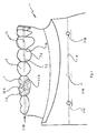
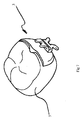
- the procedure is as follows: A gypsum model of his lower jaw is created by a patient, which is to be treated orthodontically. The plaster model is sawn, with the teeth separated. Subsequently, the teeth in a target set-up 11, s. Fig. 1 , arranged to represent the desired treatment result at the end of the treatment.
- brackets 1 are glued to the teeth 5 to be treated.
- lingual brackets 1 are glued to the teeth to be treated, in Fig. 1
- Representative only a bracket 1 on the tooth 46 is shown in dashed lines.
- an orthodontic wire 13 is guided for illustration, also only shown in phantom to exert a force on the teeth 5 via the slots 3S and the brackets 1 in order to move the respective teeth 5 to a desired position.
- all slots 3S of the brackets 1 should lie substantially in one plane, the so-called slot plane 3SE, as in FIG Fig. 1 shown.
- the method according to the invention conforms to some conventional orthodontic treatment planning method: a gypsum target set-up 11 is made, and brackets 1 are glued to the teeth 5, the slots 3S of the brackets being in a plane 3SE.
- a reference plane 9 is now defined.
- the reference plane 9 is in Fig. 1 shown in dashed lines. In the present case, it is defined by three reference plane markings 9M in the form of circles on the plaster model whose respective center points define the reference plane 9. Of the three reference plane markings 9M, one is shown in phantom since it is on the opposite (hidden left) side of the plaster model.
- the reference plane 9 has a fixed distance from the lower edge 3US of the slots 3S of the brackets 1, for example a distance from an interval of 1 to 10 cm, in the present case 3 cm.
- brackets 1 are removed from the target set-up 11, whereby the target set-up 11 of the Fig. 1 without the dashed bracket 1 and the dashed wire 13 results.
- the target set-up 11 thus prepared is now scanned by means of a scanner and the digital computer model of the target set-up 11 is stored in a computer.
- the computer thus has a model of the target set-up 11, which also contains the reference plane 9. Because the computer model contains the reference plane 9 and the relation between slot plane 3S and reference plane 9 is known, the slot model 3S is also defined for the computer model.
- a marking for the lower edge 3US of the slot plane 3SE of the slot 3S of the bracket 1 belonging to the tooth concerned is added to the tooth 5.
- a holding section for the tooth is added to the computer model, shown here by way of example in the form of a pin.
- the holding portion is added to the computer model of the tooth such that an edge of the holding portion is located at the level of the lower edge 3US of the slot 3S.
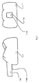
- the computer model of the tooth now results from the representation of the Fig. 2 ,
- Fig. 2 shows two side views of a 3D model of the tooth 5, for which a replacement bracket is to be produced. Only the portion lying above the gingival margin, ie the area of the tooth 5 normally visible to the patient, can be seen from the tooth 5.
- a holding portion 5H in the form of a pin has been added to the tooth 5 as a holder.
- the holding portion 5H has a cross-section substantially the shape of a rectangle, wherein the in Fig. 2 upper side edge of the rectangle is slightly shortened compared to the lower one.
- the holding portion 5H is arranged on the model of the tooth 5 so that the in Fig. 2
- the lower side edge is a marking 5MS for the slot plane, ie this edge is arranged at the level of the lower edge 3US of the slot 3S of the associated bracket 1.
- the computer thus has a model of the tooth 5 for which a replacement bracket is to be produced.
- the model has been widened around the holding section 5H, which has the shape of a pin and whose one edge is arranged at the level of the lower edge 3US of the slot 3S of the associated bracket 1.
- Fig. 2 is produced in the next step as a physical model, for example, printed or manufactured using a 3D printer made of plastic. There is then a plastic model of the tooth 5 which has a height mark for the lower edge 3US of the slot 3S and has a holding portion 5H for holding the physical model.
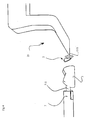
- Fig. 3 shows the front view of a holding section holder 7 of a technician holder, which is adapted to receive the holding portion 5H of the printed tooth 5, and the side view of a slot receiving 15 another technician holder for receiving a slot 3S.
- the slot holder 15 has in the view of Fig. 3 in the vertical direction at the free end, the thickness of a slot-filling orthodontic wire.
- the free end in this way simulates a slot-filling orthodontic wire, ie it forms a wire simulator 15S.
- a slot 3S of a bracket can thus be slid backlash-free on this wire simulator 15S, as described below.
- the underside 15SUS of the wire simulator 15S is at the same height as the bottom edge 3US of a slot 3S of the bracket 1 associated with the tooth 5, as shown in FIG Fig. 3 shown.
- the holding section receptacle 7 has centrally a recess 7A, which is dimensioned in such a way that the holding section 5H of the printed tooth 5 can be inserted in a form-fitting manner.
- the in Fig. 3 lower edge of the recess 7A at the level of the lower edge 3US of the slot 3 of the bracket 5 associated with the tooth 5.
- the bearing surface 7AF of the holding portion receptacle 7, on which the lower surface 15SUS rests, is at the same height as the lower surface of the recess 7A.
- the slot receptacle 15 on the one technician holder and the holding section receptacle 7 on the other technician holder thus each have edges which lie at the level of the lower edge 3US of the slot 3S of the bracket 1 associated with the tooth 5.
- these heights are adjusted to each other as in Fig. 3 shown.
- the underside 15SUS is placed on the illustrated bearing surface 7AF of the holding section receptacle 7 and thus aligned the mutual zero points of the slot receiving 15 and the holding section receptacle 7 to each other, whereby the height adjustment is completed.
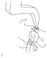
- the printed tooth 5 with its holding section 5H is inserted into the recess 7A of the holding section receptacle 7 and a standard bracket 2 is placed on the wire simulator 15S of the slot receptacle 15, as in FIG Fig. 4 shown. Again Fig. 4 further, the printed tooth 5 and the standard bracket 2 become brought together to put the standard bracket 2 suitable on the printed tooth 5.
- Fig. 5 shows a perspective view of the in Fig. 4 illustrated arrangement.
- Fig. 6 shows from different views the glued to the printed tooth 5 standard bracket 2, which now forms the replacement bracket 3.
- the replacement bracket 3 thus includes the standard bracket 2 and the individualized pad, which is formed from the cured plastic material ,
- the replacement bracket 3 can be positively adhered to the tooth 5 of the patient by the individualized pad.
- a lingual bracket was produced.
- the method can be used in the same way to make buccal brackets.
- the reference plane 9 has been represented in the method described above as a plane that applies to all the teeth 5 of a patient's jaw. However, it may be necessary to define the reference plane 9 only for individual regions of a jaw, i. to divide into intervals. In some cases, it is necessary to lower the slab plane and thus the reference plane in the left and / or right posterior region for orthodontic reasons. In such a case, the reference plane from 47 to 33 may be at a height and may be at a different height, for example 1mm from the other, for the range of 34 to 37. In another case, a reference plane of 33 to 43 may be defined, and in the range of 34 to 37, a dip of 0.5mm and in the range of 44 to 47 a dip of 1mm may be defined.
- the reference plane gets variable heights in defined sections by adjusting the slot plane in these sections.
- the reference plane 9 can be arranged on the same side as the brackets 1, i. in buccal brackets on the buccal side and in lingual brackets on the lingual side. Alternatively, however, it is also possible to draw the reference plane on the other side. Thus, for example, it is possible to draw the reference plane 9 on the lingual side in buccal brackets, in particular on the lingual side of some selected or all teeth. In this way, the reference plane 9 can be drawn individually for each tooth and in a small spatial distance from the slot 3S of the associated bracket 1. Thus, for example, it is possible, the lower edge 3US of a slot 3S of a bracket 1 as a reference plane 9 for the associated To use tooth 5.
- the gypsum target set-up was created.
- the further steps, such as placing brackets on the teeth, defining the slot plane and defining the reference plane, can also be performed directly in the software.
- the resulting virtual set-up can be stored with the brackets, the orthodontic wire, the Slotebene and the reference plane or even with parts thereof, for example. Only with the Slotebene and the reference level. Then meets a request for the production of a replacement bracket, so the desired portion of the tooth can be made directly from the model out.
- the area of the tooth 5 visible to the patient was manually cut out of the rest of the computer model of the target set-up 11.
- it may be sufficient to select a small portion of the tooth for example, to print only the buccal half of the tooth without the lingual half of the tooth.
- it may also be necessary to select a larger section for example a gingival section 5g, s. Fig. 1 , or also mesial and / or distal sections 5m, 5d of adjacent teeth 5, s. Fig. 1 to add.
- the setting of the relevant section can be done manually as described above. But it is also possible to have the relevant section defined by a software. For example, using an Edge Finder algorithm, you can always use tooth 5, as in Fig. 2 shown, automatically found and cut out of the rest of the computer model.
- the above-described method for making a replacement bracket generates a patient-specific pad for a standard bracket.
- the pad and bracket body are one unit and the patient-specific pad is created to make the patient-specific replacement bracket.
- there are also other manufacturing methods for patient-specific brackets in which, for example, first a pad is made with a patient-specific adhesive surface and then the pad thus produced is combined with a bracket body to form a bracket.
- Such a manufacturing method is, for example, in DE102011003892 disclosed.
- the production process according to the invention is also suitable for this type of production process. For this purpose can be proceeded as described above and it must be in Fig. 4 and 5 are merely placed on the slot holder 15 of the bracket body and placed on the printed tooth 5, the patient-specific pad to subsequently attach the bracket body on the individualized pad, eg. By laser welding to produce the patient-specific replacement bracket.
- a holding portion 5H has been added to the computer model of the tooth 5 as a mark for the slot plane added.
- the height of the holding section 5H has been determined such that its lower edge lies at the level of the lower edge 3US of the slot 3S of the bracket.
- the holding section 5H can be arranged, for example, mesially, lingually or distally for a buccal bracket.
- the slot plane is set on the tooth by means of a 3D marking, such as by the pin-shaped holding portion 5H according to the Fig. 2 .
- a 3D marking such as by the pin-shaped holding portion 5H according to the Fig. 2 .
- slot plane on the tooth is determined unambiguously, ie without free degree of freedom, by means of a 3D marking at a predetermined location, for example by virtue of the fact that the holding section 5H of FIG Fig. 2 is printed at the same height along the circumference of the tooth at a certain circumferential point, so slotting height, angulation, torque and rotation, ie the rotation about the tooth longitudinal axis, the bracket set.
- additional information i. a Bracketrand condition
- a straight line passing through the bracket center and perpendicular to a surface of the bracket may be used.
- the slot of the bracket i. whose location or arrangement in space, be stored with.
- the in Fig. 1 illustrated target set-up 11 is first stored with brackets and then without brackets. Starting from The computer model without brackets is then added to the tooth 5 in the method according to the invention, for example, a in Fig. 2 shown holding section 5H. The position of the holding section 5H along the circumference of the tooth is then determined with the aid of the computer model with brackets: the model with brackets is loaded over the other model and the holding section 5H is displaced along the tooth circumference, for example, until it is out of alignment with the bracket.
- Set-Up 11 is exactly opposite, ie that the longitudinal axis of the holding portion 5H is exactly perpendicular to the longitudinal axis of the slot and through the slot center.
- the arranging of the standard bracket 2 according to the Fig. 4 and 5 corresponds, the bracket are aligned on the holding portion 5H until the standard bracket 2 is the holding portion 5H exactly opposite.
- the standard bracket 2 then has exactly the same position as the bracket 1 when scanning the models with and without brackets.
Landscapes
- Health & Medical Sciences (AREA)
- Life Sciences & Earth Sciences (AREA)
- Veterinary Medicine (AREA)
- Epidemiology (AREA)
- Dentistry (AREA)
- Animal Behavior & Ethology (AREA)
- General Health & Medical Sciences (AREA)
- Public Health (AREA)
- Oral & Maxillofacial Surgery (AREA)
- Engineering & Computer Science (AREA)
- General Engineering & Computer Science (AREA)
- Dental Tools And Instruments Or Auxiliary Dental Instruments (AREA)
- Chemical & Material Sciences (AREA)
- Manufacturing & Machinery (AREA)
- Materials Engineering (AREA)
- Biomedical Technology (AREA)
- Biophysics (AREA)
Description
Die Erfindung betrifft ein Verfahren zum Herstellen eines patientenspezifischen Ersatzbrackets für eine kieferorthopädische Behandlung, wie in Anspruch 1 definiert.The invention relates to a method for producing a patient-specific replacement brace for orthodontic treatment, as defined in
Für die kieferorthopädische Behandlung von Patienten mit festsitzenden Klammern werden Brackets auf die zu behandelnden Zähne des Patienten geklebt und durch einen kieferorthopädischen Draht miteinander verbunden. Die Brackets weisen ein Pad zur Verbindung mit dem Zahn und einen Bracketbody mit einem Slot auf, der den Draht aufnimmt.For the orthodontic treatment of patients with fixed braces, brackets are glued to the patient's teeth to be treated and connected by an orthodontic wire. The brackets have a pad for connection to the tooth and a bracket body with a slot that receives the wire.
Bevorzugt werden für die kieferorthopädische Behandlung Brackets verwendet, die ein individualisiertes Pad haben, d.h. das Pad des Brackets weist eine Klebefläche zur Verbindung mit dem Zahn auf, die an den jeweiligen Zahn angepasst ist, so dass das Bracket in einer bestimmten Lage formschlüssig auf den Zahn gesetzt werden kann.Brackets are preferably used for the orthodontic treatment, which have an individualized pad, ie the pad of the bracket has an adhesive surface to Connection with the tooth, which is adapted to the respective tooth, so that the bracket can be positively placed on the tooth in a certain position.
Im Laufe der Behandlung kann es vorkommen, dass sich ein Bracket von seinem Zahn löst und es daher ersetzt werden muss.In the course of treatment, it may happen that a bracket detaches from its tooth and it therefore needs to be replaced.
In einem solchen Fall wird typischerweise an Hand des vorhandenen Ziel-Set-Ups aus Gips ein vollständig individualisiertes Ersatzbracket hergestellt. Das Verfahren gestaltet sich in der Praxis insbesondere dadurch aufwändig, dass das bereits vorhandene Ziel-Set-Up in der Regel erst in eine Technikerwerkstatt gesandt werden muss und dort dann das Ersatzbracket hergestellt und zurück gesandt werden muss.In such a case, a completely individualized replacement bracket is typically made using the existing gypsum target set-up. In practice, the method is complicated in particular in that the already existing target set-up generally only has to be sent to a technician's workshop and then the replacement bracket has to be produced there and sent back.
Ein Nachteil bei der Herstellung eines vollständig individualisierten Ersatzbrackets ist, dass das Verfahren aufwändig ist, insbesondere Gipsmodelle von Set-Ups versandt werden müssen.A disadvantage in the production of a completely individualized replacement bracket is that the method is complex, in particular plaster models of set-ups must be shipped.
Die
Die
Die
Aufgabe der vorliegenden Erfindung ist es daher, ein einfacheres und kostengünstigeres Verfahren zur Herstellung eines vollständig individualisierten Ersatzbrackets anzugeben.The object of the present invention is therefore to provide a simpler and more cost-effective method for producing a completely individualized replacement bracket.
Die Aufgabe wird erfindungsgemäß durch ein Verfahren mit den Merkmalen des Anspruchs 1 gelöst.The object is achieved by a method having the features of
Vorteilhaft umfasst der Schritt 1a): 2a) Erstellen eines patientenspezifischen Ziel-Set-Ups des Ober- oder Unterkiefers eines Patienten, 2b) Bestimmen einer Slotebene von auf zu behandelnden Zähnen des Ober- oder Unterkiefers anzuordnenden Brackets, 2c) Anordnen von Brackets auf den zu behandelnden Zähnen des Ober- oder Unterkiefers, 2d) Bestimmen der Referenzebene in dem Ziel-Set-Up relativ zu der Slotebene, 2e) Entfernen der Brackets von dem Ziel-Set-Up und 2f) elektronische Speicherung des Ziel-Set-Ups, einschließlich der Referenzebene.Advantageously, step 1a) comprises: 2a) establishing a patient-specific target set-up of the upper or lower jaw of a patient, 2b) determining a slot plane of brackets to be arranged on the teeth to be treated of the upper or lower jaw, 2c) arranging brackets on the 2d) determining the reference plane in the target set-up relative to the slot plane, 2e) removing the brackets from the target set-up, and 2f) electronically storing the target set-up, including the reference plane.
Bevorzugt wird der Schritt 2a) an Hand eines Gipsmodells oder an Hand eines virtuellen Modells des Ober- oder Unterkiefers durchgeführt.Preferably, step 2a) is performed on the basis of a plaster model or on the basis of a virtual model of the upper or lower jaw.
Der Schritt 2d) kann vor dem Schritt 2c) durchgeführt werden.Step 2d) may be performed before step 2c).
Im Schritt 2f) erfolgt die elektronische Speicherung bevorzugt durch Scannen eines physikalischen Ziel-Set-Ups oder durch Abspeichern eines digitalen Ziel-Set-Ups.In step 2f), the electronic storage preferably takes place by scanning a physical target set-up or by storing a digital target set-up.
Im Schritt 1f) kann als Bracketelement ein Lingual- oder Bukkalbracketelement bereitgestellt werden, um als Ersatzbracket ein Lingualbracket oder ein Bukkalbracket herzustellen.In step 1f), a lingual or buccal bracket element can be provided as the bracket element in order to produce a lingual bracket or a buccal bracket as a replacement bracket.
Die Referenzebene im Schritt 1a) kann kontinuierlich, bspw. durch eine Linie, oder intermittierend, bspw. durch Strichpunkte an ausgewählten Zähnen, dargestellt werden.The reference plane in step 1a) can be represented continuously, for example by a line, or intermittently, for example by semicolons on selected teeth.
Die Referenzebene im Schritt 1a) kann für alle Zähne gleich definiert werden, bspw. von 18 bis 28, oder für einen ausgewählten Bereich definiert werden, bspw. von 13 bis 23, und für die übrigen Bereiche eine relative Verschiebung dazu, bspw. eine Absenkung oder Anhebung der Referenzebene, definiert werden.The reference plane in step 1a) can be defined identically for all teeth, for example from 18 to 28, or defined for a selected region, for example from 13 to 23, and for the remaining regions a relative shift thereto, for example a depression or raising the reference plane.
Die Referenzebene kann in einem festen Abstand, bspw. 3-6cm, von der Slotebene oder individuell festgelegt werden, insbesondere Referenzebene und Slotebene identisch sind.The reference plane can be defined at a fixed distance, for example 3-6 cm, from the slot plane or individually, in particular the reference plane and slot plane are identical.
Der im Schritt 1c) festzulegende relevante Ausschnitt kann mindestens einen Abschnitt des Zahns und vorzugsweise den Zahn, insbesondere zusätzlich mit einem gingivalen Abschnitt, optional zusätzlich mindestens einen Abschnitt des mesial und/oder distal benachbarten Zahns, vorzugsweise den ganzen Zahn, insbesondere jeweils zusätzlich mit einem gingivalen Abschnitt, umfassen.The relevant cutout to be determined in step 1c) may comprise at least a portion of the tooth, and preferably the tooth, in particular additionally with a gingival section, optionally additionally at least a portion of the mesially and / or distally adjacent tooth, preferably the entire tooth, in particular in each case additionally with one gingival section, include.
Die Markierung kann als 2D-Linie oder als 3D-Körper, insbesondere als Halteabschnitt für den Zahn, ausgebildet werden.The marking can be formed as a 2D line or as a 3D body, in particular as a holding section for the tooth.
Die Markierung kann im Fall einer 2D-Linie auf der Ober- oder Unterkante eines Slots in der Slotebene oder im Fall eines 3D-Körpers auf der Höhe der Slotebene angeordnet werden, wobei im letzteren Fall der 3D-Körper in okklusal-gingivaler Richtung bevorzugt eine Dicke aufweist, die der Höhe der Slots der Brackets in dieser Richtung entspricht.In the case of a 2D line, the marking may be arranged on the upper or lower edge of a slot in the slot plane or, in the case of a 3D body, on the level of the slot plane, in the latter case the 3D body preferably in the occlusal-gingival direction Thickness corresponding to the height of the slots of the brackets in this direction.
Der Halteabschnitt wird für Bukkalbrackets bevorzugt lingual und für Lingualbrackets bevorzugt bukkal angeordnet.The holding section is preferably arranged lingually for buccal brackets and preferably buccally for lingual brackets.
Der Halteabschnitt wird im Schritt 1g) bevorzugt mit einem Techniker-Halter verbunden.The holding section is preferably connected to a technician holder in step 1g).
Das Erstellen des Modells im Schritt 1e) kann durch ein Ausdrucken des Ausschnitts mit einem 3D-Drucker oder mit Hilfe einer CNC-Maschine oder einer Rapid-Prototyping-Maschine erfolgen.The creation of the model in step 1e) can be done by printing the section with a 3D printer or by means of a CNC machine or a rapid prototyping machine.
Der Ausschnitt im Schritt 1c) kann manuell oder automatisch, bspw. durch eine Software, festgelegt werden.The section in step 1c) can be determined manually or automatically, for example by software.
Im Schritt 1h) kann der Bracketbody mit einem individualisierten Pad verbunden werden bzw. das Standardbracket mit einem individualisierten Pad versehen werden, bspw. durch Ausfüllen eines Spalts zwischen dem Zahn und dem Pad des Standardbrackets mit einem Kunststoffmaterial und Aushärten desselben.In step 1h), the bracket body can be connected to an individualized pad or the standard bracket can be provided with an individualized pad, for example by filling a gap between the tooth and the pad of the standard bracket with a plastic material and curing it.
Im Schritt 1d) kann eine 2D-Markierung erzeugt werden, bspw. in Form einer Linie oder Punkten, wodurch die Slothöhe und die Angulation des zugehörigen Brackets festgelegt sind.In step 1d), a 2D mark can be generated, for example in the form of a line or points, whereby the height of the slide and the angulation of the associated bracket are determined.
Im Schritt 1d) kann eine 3D-Markierung erzeugt werden, bspw. in Form eines Zapfens, wodurch die Slothöhe, die Angulation und der Torque des zugehörigen Brackets festgelegt sind.In step 1d), a 3D marking can be generated, for example in the form of a pin, whereby the height of the slit, the angulation and the torque of the associated bracket are determined.
Im Schritt 1d) kann eine 3D-Markierung unter zu Hilfenahme von mindestens einer Bracketrandbedingung erzeugt werden, bspw. in Form eines Zapfens, wodurch die Slothöhe, die Angulation, der Torque und die Rotation des zugehörigen Brackets festgelegt sind.In step 1d), a 3D marking can be generated with the aid of at least one Bracketrand condition, for example in the form of a pin, whereby the height of the slide, the angulation, the torque and the rotation of the associated bracket are determined.
Als Bracketrandbedingung kann eine Senkrechte auf einen Bracketmittelpunkt, die senkrecht zum Slot verläuft, oder die Lage und der Verlauf des Slots verwendet werden, wobei die Randbedingung vorzugsweise zusätzlich in der im Schritt 1a) bereitgestellten 3D-Darstellung des Ober- oder Unterkiefers gespeichert ist.As Bracketrandbedingung a perpendicular to a bracket center, which is perpendicular to the slot, or the location and the course of the slot can be used, the boundary condition is preferably additionally stored in the provided in step 1a) 3D representation of the upper or lower jaw.
Als Markierung wird bevorzugt ein zapfenförmiger Halteabschnitt erzeugt, der eine Seitenfläche aufweist, die auf Höhe der Ober- bzw. Unterkante des Slots des zugehörigen Brackets angeordnet ist.As marking, a pin-shaped holding section is preferably produced, which has a side surface which is arranged at the level of the upper or lower edge of the slot of the associated bracket.
Weitere Merkmale, Einzelheiten und Vorzüge der Erfindung ergeben sich aus den Ansprüchen und der nachfolgenden Beschreibung bevorzugter Ausführungsformen sowie anhand der Zeichnung. Es zeigen:
- Fig. 1
- eine bukkale Seitenansicht eines Ziel-Set-Ups eines Unterkiefers von rechts im Gipsmodell,
- Fig. 2
- zwei Seitenansichten eines Zahnabschnitts mit einem Halteelement,
- Fig. 3
- einen Höhenabgleich zwischen einer Zahnaufnahme für den Zahnabschnitt der
Fig. 2 und einem Halter für das Bracketelement mit einem Slot, - Fig. 4
- eine Seitenansicht der Zahnaufnahme mit eingesteckten Zahnabschnitt sowie einen Halter mit aufgestecktem Bracket,
- Fig. 5
- eine perspektivische Ansicht der
Fig. 4 , - Fig. 6
- verschiedene Ansichten bei denen das Bracket auf den Zahnabschnitt geklebt ist, und
- Fig. 7
- eine perspektivische Ansicht des Zahnabschnitts mit Bracket der
Fig. 6 , jedoch ohne Halteelement.
- Fig. 1
- a buccal side view of a target set-up of a lower jaw from the right in the plaster model,
- Fig. 2
- two side views of a tooth section with a holding element,
- Fig. 3
- a height adjustment between a tooth receptacle for the tooth portion of
Fig. 2 and a holder for the bracket element with a slot, - Fig. 4
- a side view of the tooth holder with inserted tooth portion and a holder with attached bracket,
- Fig. 5
- a perspective view of
Fig. 4 . - Fig. 6
- different views in which the bracket is glued to the tooth portion, and
- Fig. 7
- a perspective view of the tooth portion with bracket of
Fig. 6 , but without holding element.
Das Verfahren wird nachfolgend anhand der Herstellung eines Ersatzbrackets für einen beliebigen Zahn eines Kiefers stellvertretend am Unterkiefer erläutert. Um erfindungsgemäß ein Ersatzbracket herzustellen, wird wie folgt vorgegangen: Von einem Patienten wird ein Gipsmodell seines Unterkiefers erstellt, der kieferorthopädisch behandelt werden soll. Das Gipsmodell wird zersägt, wobei die Zähne separiert werden. Anschließend werden die Zähne in einem Ziel-Set-Up 11, s.
Dann werden Brackets 1 auf die zu behandelnden Zähne 5 geklebt. In dem Ziel-Set-Up 11 der
Bis zu diesem Punkt entspricht das erfindungsgemäße Verfahren manchen herkömmlichen Planungsverfahren für eine kieferorthopädische Behandlung: Es wird ein Ziel-Set-Up 11 aus Gips hergestellt und auf die Zähne 5 werden Brackets 1 geklebt, wobei die Slots 3S der Brackets in einer Ebene 3SE liegen.Up to this point, the method according to the invention conforms to some conventional orthodontic treatment planning method: a gypsum target set-
In einem definierten Abstand von der Slotebene 3SE, bspw. der Oberkante 30S oder der Unterkante 3US der Slots 3S der Brackets 1, wird nun eine Referenzebene 9 definiert. Die Referenzebene 9 ist in
Ist die Referenzebene 9 definiert und auf dem Ziel-Set-Up 11 eingezeichnet, so werden die Brackets 1 von dem Ziel-Set-Up 11 entfernt, wodurch sich das Ziel-Set-Up 11 der
Das auf diese Weise hergestellte Ziel-Set-Up 11 wird nun mit Hilfe eines Scanners gescannt und das digitale Computermodell des Ziel-Set-Ups 11 wird in einem Computer gespeichert. In dem Computer liegt somit ein Modell des Ziel-Set-Ups 11 vor, das auch die Referenzebene 9 enthält. Dadurch, dass das Computermodell die Referenzebene 9 enthält und die Relation zwischen Slotebene 3S und Referenzebene 9 bekannt ist, ist für das Computermodell auch die Slotebene 3S definiert.The target set-
Trifft nun die Anforderung ein, ein Ersatzbracket für einen bestimmten Zahn herzustellen, wird wie folgend beschrieben vorgegangen.If the requirement now arises to produce a replacement bracket for a particular tooth, the procedure is as described below.
Es wird das o.g. Computermodell des Ziel-Set-Ups 11 in den Computer geladen. Der Zahn 5, für den das Ersatzbracket hergestellt werden soll, wird in dem Modell ausgewählt und von Hand aus dem übrigen Modell herausgeschnitten, so dass nur noch das Computermodell des betroffenen Zahns 5 zur folgenden Bearbeitung vorliegt.It will be the o.g. Computer model of the target set-
Mit Hilfe der Referenzebene 9, die in dem Computermodell noch zur Verfügung steht, wird dem Zahn 5 eine Markierung für die Unterkante 3US der Slotebene 3SE des Slots 3S des dem betroffenen Zahns 5 zugehörigen Brackets 1 hinzugefügt. Um das physische Modell des Zahns in den folgenden Arbeitsschritten handhaben zu können, wird dem Computermodell ein Halteabschnitt für den Zahn hinzugefügt, vorliegend beispielhaft in Form eines Zapfens gezeigt. Zur Vereinfachung wird der Halteabschnitt derart dem Computermodell des Zahns hinzugefügt, dass eine Kante des Halteabschnitts auf Höhe der Unterkante 3US des Slots 3S angeordnet ist. Das Computermodell des Zahns ergibt sich nun aus der Darstellung der
In dem Computer liegt somit ein Modell des Zahns 5 vor, für den ein Ersatzbracket hergestellt werden soll. Das Modell wurde erweitert um den Halteabschnitt 5H, der die Form eines Zapfens aufweist und dessen eine Kante auf der Höhe der Unterkante 3US des Slots 3S des zugehörigen Brackets 1 angeordnet ist.The computer thus has a model of the
Das auf diese Weise erstellte Computermodell der
Die Slotaufnahme 15 hat in der Ansicht der
Die Halteabschnittaufnahme 7 weist zentral eine Ausnehmung 7A auf, die derart bemessen ist, dass in diese der Halteabschnitt 5H des ausgedruckten Zahns 5 formschlüssig gesteckt werden kann. Wie oben beschrieben, liegt die in
Die Slotaufnahme 15 an dem einen Techniker-Halter und die Halteabschnittaufnahme 7 an dem anderen Techniker-Halter haben somit jeweils Kanten, die auf der Höhe der Unterkante 3US des Slots 3S des dem Zahn 5 zugehörigen Brackets 1 liegen. Um diese Höhen auf den gleichen Nullpunkt zu beziehen, werden diese Höhen aneinander abgeglichen, wie in
In einem nächsten Verfahrensschritt wird der ausgedruckte Zahn 5 mit seinem Halteabschnitt 5H in die Ausnehmung 7A der Halteabschnittaufnahme 7 gesteckt und ein Standardbracket 2 auf den Drahtsimulator 15S der Slotaufnahme 15 gesteckt, wie in
Ist das Standardbracket 2 geeignet relativ zum ausgedruckten Zahn 5 positioniert, so wird ein Spalt zwischen dem Pad des Standardbrackets 2 und dem ausgedruckten Zahn 5 mit einem Kunststoffmaterial bzw. einem Klebstoff gefüllt und ausgehärtet, um ein patientenspezifisches Pad für das Standardbracket 2 zu bilden.When the
Ist die Härtung erfolgt, kann der Techniker-Halter mit der Slotaufnahme entfernt werden, wodurch sich die in
Folgend wird der Halteabschnitt 5H aus der Ausnehmung 7A heraus gezogen und der Halteabschnitt 5H von dem ausgedruckten Zahn 5 entfernt, bspw. abgeschliffen, wodurch sich die Anordnung der
Kommt die Anordnung der
Das Ersatzbracket 3 kann durch das individualisierte Pad formschlüssig auf den Zahn 5 des Patienten geklebt werden.The
In dem o.g. Verfahren zur Herstellung eines Ersatzbrackets wurde ein Lingualbracket hergestellt. Das Verfahren kann jedoch auf gleiche Weise verwendet werden, um Bukkalbrackets herzustellen.In the above-mentioned method for producing a replacement bracket, a lingual bracket was produced. However, the method can be used in the same way to make buccal brackets.
Die Referenzebene 9 wurde in dem oben beschriebenen Verfahren als eine Ebene dargestellt, die für alle Zähne 5 eines Kiefers eines Patienten gilt. Es kann jedoch notwendig sein, die Referenzebene 9 jeweils nur für einzelne Bereiche eines Kiefers zu definieren, d.h. in Intervalle zu unterteilen. In einigen Fällen erweist es sich als notwendig, die Slotebene und somit die Referenzebene im linken und/oder rechten Seitenzahnbereich aus kieferorthopädischen Gründen abzusenken. In einem solchen Fall kann die Referenzebene von 47 bis 33 auf einer Höhe liegen und für den Bereich von 34 bis 37 auf einer anderen Höhe, bspw. 1mm gegenüber der anderen abgesenkt, liegen. In einem anderen Fall kann eine Referenzebene von 33 bis 43 definiert werden und in dem Bereich von 34 bis 37 eine Absenkung um 0,5mm und in dem Bereich von 44 bis 47 eine Absenkung von 1mm definiert werden. In derartigen Fällen kann es ausreichend sein, lediglich die Absenkung oder Anhebung in den betroffenen Zahnbereichen und die betroffenen Zahnbereiche zu notieren und die Absenkung oder Anhebung nicht in dem Modell einzuzeichnen. Auf diese Weise erhält die Referenzebene in definierten Abschnitten variable Höhen durch die Anpassung der Slotebene in diesen Abschnitten.The
Die Referenzebene 9 kann auf derselben Seite wie die Brackets 1 angeordnet werden, d.h. bei bukkalen Brackets auf der bukkalen Seite und bei lingualen Brackets auf der lingualen Seite eingezeichnet werden. Alternativ ist es jedoch auch möglich, die Referenzebene auf der jeweils anderen Seite einzuzeichnen. So ist es bspw. möglich, bei bukkalen Brackets die Referenzebene 9 auf der lingualen Seite einzuzeichnen, insbesondere auf der lingualen Seite mancher ausgewählter oder aller Zähne. Auf diese Weise kann die Referenzebene 9 individuell für jeden Zahn eingezeichnet werden und in einem geringen räumlichen Abstand von dem Slot 3S des zugehörigen Brackets 1. So ist es bspw. möglich, die Unterkante 3US eines Slots 3S eines Brackets 1 als Referenzebene 9 für den zugehörigen Zahn 5 zu verwenden.The
In dem oben beschriebenen Verfahren zur Herstellung eines Ersatzbrackets wurde das Ziel-Set-Up aus Gips erstellt. Alternativ ist es möglich, das Ziel-Set-Up in einem Computer mit Hilfe einer Software zu erstellen. Auch die weiteren Schritte, wie bspw. das Anordnen von Brackets auf den Zähnen, das Definieren der Slotebene und das Definieren der Referenzebene, können direkt in der Software ausgeführt werden. Das sich dabei ergebende virtuelle Set-Up kann mit den Brackets, dem kieferorthopädischen Draht, der Slotebene und der Referenzebene gespeichert werden oder auch nur mit Teilen davon, bspw. nur mit der Slotebene und der Referenzebene. Trifft dann eine Anforderung zur Herstellung eines Ersatzbrackets ein, so kann aus dem Modell direkt heraus der gewünschte Abschnitt des Zahns hergestellt werden.In the replacement bracket manufacturing method described above, the gypsum target set-up was created. Alternatively, it is possible to create the target set-up in a computer using software. The further steps, such as placing brackets on the teeth, defining the slot plane and defining the reference plane, can also be performed directly in the software. The resulting virtual set-up can be stored with the brackets, the orthodontic wire, the Slotebene and the reference plane or even with parts thereof, for example. Only with the Slotebene and the reference level. Then meets a request for the production of a replacement bracket, so the desired portion of the tooth can be made directly from the model out.
Um das Ersatzbracket für den Zahn 5 herzustellen, wurde in dem oben beschriebenen Verfahren der beim Patienten sichtbare Bereich des Zahns 5 von Hand aus dem übrigen Computermodell des Ziel-Set-Ups 11 herausgeschnitten. Für die Herstellung des Ersatzbrackets kann es jedoch ausreichen, einen kleinen Abschnitt des Zahns auszuwählen, bspw. nur die bukkale Hälfte des Zahns auszudrucken ohne die linguale Hälfte des Zahns. Es kann aber auch notwendig sein, einen größeren Abschnitt auszuwählen, bspw. einen gingivalen Abschnitt 5g, s.
Das oben beschriebene Verfahren zur Herstellung eines Ersatzbrackets generiert ein patientenspezifisches Pad für ein Standardbracket. Bei dem Standardbracket sind Pad und Bracketbody eine Einheit und es wird das patientenspezifische Pad erzeugt, um das patientenspezifische Ersatzbracket herzustellen. Es gibt jedoch auch andere Herstellungsverfahren für patientenspezifische Brackets, bei denen z.B. erst ein Pad mit einer patientenspezifischen Klebefläche hergestellt wird und dann das auf diese Weise hergestellte Pad mit einem Bracketbody zu einem Bracket vereinigt wird. Ein derartiges Herstellungsverfahren ist bspw. in
In dem oben beschriebenen Verfahren zur Herstellung eines Ersatzbrackets wurde als Markierung für die Slotebene ein Halteabschnitt 5H dem Computermodell des Zahns 5 hinzugefügt. Dabei wurde lediglich die Höhe des Halteabschnitts 5H so festgelegt, dass dessen Unterkante auf der Höhe der Unterkante 3US des Slots 3S des Brackets liegt. Wo der Halteabschnitt 5H entlang des Zahnumfangs (auf derselben Höhe) liegt, ist vorliegend ohne Bedeutung, so kann der Halteabschnitt 5H bspw. mesial, lingual oder distal angeordnet sein für ein bukkales Bracket.In the above-described method for manufacturing a replacement bracket, a holding portion 5H has been added to the computer model of the
Bei verschiedenen Arten von Markierungen der Slotebene auf dem Zahn im Computermodell können verschiedene andere Parameter der Behandlung des Zahns festgelegt werden:
- Wird die Slotebene auf dem Zahn mit Hilfe einer 2D-Markierung festgelegt, bspw. durch eine Linie, Streifen oder eine Reihe von Punkten, so sind durch diese Markierung lediglich die Slothöhe und die Angulation, d.h. die Kippung in mesial-distaler Richtung, des Brackets festgelegt.
- If the slot plane on the tooth is determined by means of a 2D marking, for example by a line, strip or a number of points, then this marking merely indicates the height of the slit and the angulation, ie the tilt in the mesial-distal direction, of the bracket established.
Wird die Slotebene auf dem Zahn mit Hilfe einer 3D-Markierung festgelegt, wie bspw. durch den zapfenförmigen Halteabschnitt 5H gemäß der
Wird die Slotebene auf dem Zahn mit Hilfe einer 3D-Markierung an einer vorbestimmten Stelle eindeutig, d.h. ohne freien Freiheitsgrad, festgelegt, bspw. dadurch, dass der Halteabschnitt 5H der
Um letztere Variante realisieren zu können, kann bspw. wie folgt vorgegangen werden: in dem Computermodell wird eine Zusatzinformation, d.h. eine Bracketrandbedingung, für jedes Bracket gespeichert, die dessen Lage am Zahn eindeutig macht. Als Zusatzinformation kann bspw. eine durch den Bracketmittelpunkt und senkrecht zu einer Oberfläche des Brackets verlaufende Gerade verwendet werden. Als Zusatzinformation kann auch der Slot des Brackets, d.h. dessen Lage bzw. Anordnung im Raum, mit abgespeichert werden.In order to be able to realize the latter variant, it is possible, for example, to proceed as follows: in the computer model, additional information, i. a Bracketrand condition, stored for each bracket that makes its location on the tooth unique. For example, as an additional information, a straight line passing through the bracket center and perpendicular to a surface of the bracket may be used. As additional information, the slot of the bracket, i. whose location or arrangement in space, be stored with.
Praktischerweise kann dazu wie folgt vorgegangen werden: Das in
- 11
- Bracketbracket
- 22
- Standardbracketstandard bracket
- 33
- Ersatzbracketreplacement bracket
- 3S3S
- Slotslot
- 3OS3OS
- Oberkante des SlotsTop of the slot
- 3US3US
- Unterkante des SlotsBottom edge of the slot
- 3SE3SE
- Slotebeneslot level
- 55
- Zahntooth
- 5d5d
- distaler Abschnittdistal section
- 5g5g
- gingivaler Abschnittgingival section
- 5H5H
- Halteabschnitt für ZahnHolding section for tooth
- 5m5 m
- mesialer Abschnittmesial section
- 5MS5MS
- Markierung für die SlotebeneMark for the slot level
- 77
- Halteabschnittaufnahme eines Techniker-Halters für den Halteabschnitt 5HHolding section pickup of a technician holder for the 5H holding section
- 7A7A
- Ausnehmung der HalteabschnittaufnahmeRecess of the holding section receptacle
- 7AF7AF
- Auflageflächebearing surface
- 99
- Referenzebenereference plane
- 9M9M
- ReferenzebenenmarkierungReference plane mark
- 1111
- Ziel-Set-Up des Unterkiefers eines PatientenTarget set-up of the lower jaw of a patient
- 1313
- kieferorthopädischer Drahtorthodontic wire
- 1515
- Slotaufnahme eines Techniker-Halters zur Aufnahme eines Slots 3SSlot recording of a technician's holder for receiving a slot 3S
- 15S15S
- Drahtsimulatorwire simulator
- 15 SUS15 SUS
- Unterseite des DrahtsimulatorsBottom of the wire simulator
Claims (22)
- Process for the manufacture of a patient-specific replacement bracket (3) comprising the following steps:a) providing a 3D representation of the supramaxilla or submaxilla of the patient in the target set-up having a reference plane (9) in a computer;b) receiving a request to manufacture a replacement bracket (3) for a tooth (5) of the supramaxilla or submaxilla;c) defining a sector of the 3D representation of the supramaxilla or submaxilla which contains at least a section of the tooth (5) for which the replacement bracket (2) is to be manufactured;d) generating a marking (5MS) for the slot plate (3SE) in the section by means of the reference plane (9);e) creating a physical model of the section with the marking (5MS);f) providing a bracket element containing the slot (3S), e.g. a bracket body or a standard bracket (2);g) aligning said bracket element (2) to the slot plane (3SE) andh) assigning an individualized pad to the bracket element, whereby the replacement bracket (3) is manufactured.
- Process according to claim 1, characterized in that the step 1a) comprises:a) creating a patient-specific target set-up (11) of the supramaxilla or submaxilla of a patient;b) determining a slot plane (3SE) of brackets (1) to be arranged on teeth (5) to be treated of the supramaxilla or submaxilla;c) arranging of brackets (1) on teeth to be treated of the supramaxilla or submaxilla;d) determining the reference plane (9) in the target set-up (11) relative to the slot plane;e) removing in the brackets (1) from the target set-up (11) andf) electronically storing the target set-up including the reference plane (9).
- Process according to one of the preceding claims, characterized in that the step 2a) is performed by means of a gypsum model or by means of a virtual model of the supramaxilla or submaxilla.
- Process according to one of the preceding claims, characterized in that the step 2d) is performed prior to the step 2c).
- Process according to one of the preceding claims, characterized in that in step 2f) the electronic storing is effected by a scanning a physical target set-up (11) or by storing a digital target set-up.
- Process according to one of the preceding claims, characterized in that in step 1f) a lingual or buccal bracket element is provided as a bracket element (2) in order to manufacture a lingual or a buccal bracket as a replacement bracket (3).
- Process according to one of the preceding claims, characterized in that the reference plane (9) in step 1a) is displayed continuously, e.g. by a line, or intermittently, e.g. by dash-dots on selected teeth (5).
- Process according to one of the preceding claims, characterized in that the reference plane (9) in step 1a) is defined the same for all teeth, for example from 18 to 28, or is defined for a selected region, for example from 13 to 23, and for the remaining regions a displacement relative thereto, for example, a lowering or raising of the reference plane (9) is defined.
- Process according to one of the preceding claims, characterized in that the reference plane (9) is defined at a fixed distance, for example 3 - 6 cm, from the slot plane (3SE), or is defined individually, particularly the reference plane is identical with the slot plane.
- Process according to one of the preceding claims, characterized in that the relevant sector to be defined in Step 1c) comprises at least a section of the tooth (5), and preferably the tooth (5), particularly with an additional gingival section (5g), optionally at least an additional section of the mesially and/or distally adjacent tooth, preferably the whole tooth, particularly each with an additional gingival section.
- Process according to one of the preceding claims, characterized in that the marking (5MS) is realized as a 2D line or as a 3D body, particularly as a retaining section (5H) for the tooth (5).
- Process according to one of the preceding claims, characterized in that in the case of a 2D line the marking (5MS) is arranged on the upper or lower edge (3OS, 3US) of a slot (3S) in the slot plane (3SE), or in the case of a 3D body is arranged at the level of the slot plane (3SE), wherein in the latter case the 3D body in occlusal-gingival direction preferably has a thickness that corresponds to the level of the slot of the brackets (1) in this direction.
- Process according to one of the preceding claims, characterized in that the retaining section (5H) is arranged lingually for buccal brackets and buccally for lingual brackets.
- Process according to one of the preceding claims, characterized in that the retaining section (5 H) in step 1g) is connected to a technician's holder.
- Process according to one of the preceding claims, characterized in that creating the model in step 1e) is effected by printing the sector by a 3D printer, or by means of a CNC machine or a rapid prototyping machine.
- Process according to one of the preceding claims, characterized in that the sector in step 1c) is defined manually or automatically, for example by a software.
- Process according to one of the preceding claims, characterized in that in step 1h) the bracket body is connected to an individualized pad, or the standard bracket (2) is provided with an individualized pad, for example, by filling a gap between the tooth (5) and the pad of the standard bracket (2) with a plastic material and curing the same.
- Process according to one of the preceding claims, characterized in that in step 1d) a 2D marking is generated, for example in the form of a line or dots, whereby the slot level and the angulation of the corresponding bracket (3) are defined.
- Process according to one of the preceding claims, characterized in that in step 1d) a 3D marking (5H) is generated, for example in the form of a pin, whereby the slot level, the angulation and the torque of the corresponding bracket (3) are defined.
- Process according to one of the preceding claims, characterized in that in step 1d) a 3D marking is generated with the help of at least one bracket constraint, for example in the form of a pin, whereby the slot level, the angulation, the torque and the rotation of the corresponding bracket are defined.
- Process according to one of the preceding claims, characterized in that a perpendicular to a bracket center that extends perpendicularly to the slot or the position and the profile of the slot is used as the bracket constraint, wherein the constraint preferably is additionally stored in the 3D representation of the supramaxilla or submaxilla provided in step 1a).
- Process according to one of the preceding claims, characterized in that as the marking a pin-shaped retaining section (5 H) is generated having a lateral surface that is arranged at the level of the upper or lower edge (30S, 3US) of the slot of the corresponding bracket.
Applications Claiming Priority (2)
| Application Number | Priority Date | Filing Date | Title |
|---|---|---|---|
| DE102013209735.2A DE102013209735A1 (en) | 2013-05-24 | 2013-05-24 | A method of making a patient-specific replacement bracket for orthodontic treatment and a bracket made by the method |
| PCT/EP2014/059897 WO2014187715A1 (en) | 2013-05-24 | 2014-05-14 | Method for producing a patient-specific replacement bracket for an orthodontic treatment, and bracket produced by this method |
Publications (2)
| Publication Number | Publication Date |
|---|---|
| EP3003201A1 EP3003201A1 (en) | 2016-04-13 |
| EP3003201B1 true EP3003201B1 (en) | 2016-09-21 |
Family
ID=50780467
Family Applications (1)
| Application Number | Title | Priority Date | Filing Date |
|---|---|---|---|
| EP14725978.2A Not-in-force EP3003201B1 (en) | 2013-05-24 | 2014-05-14 | Method for producing a patient-specific replacement bracket for an orthodontic treatment |
Country Status (8)
| Country | Link |
|---|---|
| US (1) | US10231800B2 (en) |
| EP (1) | EP3003201B1 (en) |
| JP (1) | JP6223548B2 (en) |
| KR (1) | KR101711545B1 (en) |
| CA (1) | CA2915121C (en) |
| DE (1) | DE102013209735A1 (en) |
| RU (1) | RU2629800C2 (en) |
| WO (1) | WO2014187715A1 (en) |
Families Citing this family (7)
| Publication number | Priority date | Publication date | Assignee | Title |
|---|---|---|---|---|
| GB201608059D0 (en) * | 2016-05-09 | 2016-06-22 | Dickenson Gary | Method and apparatus for positioning a dental bracket element |
| KR102028801B1 (en) | 2017-08-18 | 2019-10-04 | 허정민 | Method And Computer Readable Recording Medium For Orthodontic Treatment Education |
| KR102157109B1 (en) * | 2018-07-03 | 2020-09-17 | 주식회사 케어덴트코리아 | Bracket Block For Manufacturing Customized Orthodontic Bracket, Customized Orthodontic Bracket, And Manufacturing Method Thereof |
| US10315353B1 (en) | 2018-11-13 | 2019-06-11 | SmileDirectClub LLC | Systems and methods for thermoforming dental aligners |
| US11007042B2 (en) | 2019-02-06 | 2021-05-18 | Sdc U.S. Smilepay Spv | Systems and methods for marking models for dental aligner fabrication |
| US10482192B1 (en) | 2019-02-12 | 2019-11-19 | SmileDirectClub LLC | Systems and methods for selecting and marking a location on a dental aligner |
| CN118395523B (en) * | 2024-06-21 | 2024-09-17 | 先临三维科技股份有限公司 | Model processing method, device, equipment and storage medium |
Family Cites Families (15)
| Publication number | Priority date | Publication date | Assignee | Title |
|---|---|---|---|---|
| AT391614B (en) * | 1988-05-31 | 1990-11-12 | Ronay Franz | METHOD AND DEVICE FOR PRODUCING AN ORTHODONTIC APPARATUS |
| DE69327661T2 (en) | 1992-11-09 | 2000-07-20 | Ormco Corp., Glendora | METHOD AND DEVICE FOR MANUFACTURING INDIVIDUALLY ADAPTED ORTHODONTIC DEVICES |
| DE19540755C2 (en) * | 1995-11-02 | 1997-08-14 | Fischer Brandies Helge Prof Me | Method for producing a wire arch used to correct a tooth misalignment |
| EP2204136B1 (en) * | 2000-04-19 | 2013-08-28 | OraMetrix, Inc. | Orthodontic archwire |
| WO2001085047A2 (en) | 2000-04-19 | 2001-11-15 | Orametrix, Inc. | Method and system for placement of orthodontic apparatus |
| US7387511B2 (en) * | 2002-01-22 | 2008-06-17 | Geodigm Corporation | Method and apparatus using a scanned image for automatically placing bracket in pre-determined locations |
| US6776614B2 (en) * | 2002-02-13 | 2004-08-17 | Lingualcare, Inc. | Modular system for customized orthodontic appliances |
| US20060275736A1 (en) * | 2005-04-22 | 2006-12-07 | Orthoclear Holdings, Inc. | Computer aided orthodontic treatment planning |
| BRPI0618785A2 (en) * | 2005-12-05 | 2013-03-05 | Brian C Reising | orthodantic support and teeth clamping method |
| US7751925B2 (en) * | 2006-01-27 | 2010-07-06 | 3M Innovative Properties Company | System to manufacture custom orthodontic appliances, program product, and related methods |
| US9326831B2 (en) * | 2006-10-20 | 2016-05-03 | Align Technology, Inc. | System and method for positioning three-dimensional brackets on teeth |
| US8562339B2 (en) | 2007-07-13 | 2013-10-22 | 3M Innovative Properties Company | Digital orthodontic appliance coupling matrix |
| US8936464B2 (en) * | 2009-02-24 | 2015-01-20 | Cadent Ltd. | Method, system and model for indirect bonding |
| DE102011003892A1 (en) | 2011-02-09 | 2012-08-09 | Hoang Viet-Ha Julius Vu | Method for producing at least one patient-specific, modularly constructed bracket and associated bracket |
| DE102011081151A1 (en) * | 2011-08-17 | 2013-02-21 | Dw Lingual Systems Gmbh | A method of deforming an orthodontic wire from a shape memory material and associated wire |
-
2013
- 2013-05-24 DE DE102013209735.2A patent/DE102013209735A1/en not_active Withdrawn
-
2014
- 2014-05-14 US US14/892,479 patent/US10231800B2/en not_active Expired - Fee Related
- 2014-05-14 RU RU2015155587A patent/RU2629800C2/en not_active IP Right Cessation
- 2014-05-14 WO PCT/EP2014/059897 patent/WO2014187715A1/en not_active Ceased
- 2014-05-14 KR KR1020157033993A patent/KR101711545B1/en not_active Expired - Fee Related
- 2014-05-14 JP JP2016514334A patent/JP6223548B2/en not_active Expired - Fee Related
- 2014-05-14 EP EP14725978.2A patent/EP3003201B1/en not_active Not-in-force
- 2014-05-14 CA CA2915121A patent/CA2915121C/en not_active Expired - Fee Related
Also Published As
| Publication number | Publication date |
|---|---|
| JP6223548B2 (en) | 2017-11-01 |
| KR101711545B1 (en) | 2017-03-02 |
| CA2915121A1 (en) | 2014-11-27 |
| CA2915121C (en) | 2017-12-05 |
| RU2629800C2 (en) | 2017-09-04 |
| US20160113737A1 (en) | 2016-04-28 |
| RU2015155587A (en) | 2017-06-29 |
| US10231800B2 (en) | 2019-03-19 |
| JP2016518946A (en) | 2016-06-30 |
| KR20160013881A (en) | 2016-02-05 |
| WO2014187715A1 (en) | 2014-11-27 |
| DE102013209735A1 (en) | 2014-11-27 |
| EP3003201A1 (en) | 2016-04-13 |
Similar Documents
| Publication | Publication Date | Title |
|---|---|---|
| EP3003201B1 (en) | Method for producing a patient-specific replacement bracket for an orthodontic treatment | |
| EP2957252B1 (en) | Method for the production of a three-dimensional true model of the actual position of at least two the teeth of a patient | |
| EP2672918B1 (en) | Method for producing a patient-specific bracket body, and associated bracket body | |
| DE102007036549B4 (en) | Orthodontic jig placement jig, set of jig combinations, manufacturing method and jig making apparatus | |
| EP3463175B1 (en) | Method of manufacture of individualized dental impression tray | |
| WO2016034509A1 (en) | Method for producing a positioning tray and the device therefor | |
| DE4439129A1 (en) | Dental articulator | |
| EP2564805A2 (en) | Method and setup model for producing a set of orthodontic splints | |
| EP3743012B1 (en) | Method for producing a dental prosthesis | |
| DE102017113814B4 (en) | Process for the production of a dental prosthesis with a defined adhesive gap | |
| EP2672919B1 (en) | Method for producing at least one patient-specific modular bracket | |
| DE102014104163A1 (en) | Method for producing a drilling template or drilling template | |
| EP2672921B1 (en) | Method for producing a patient-specific support, and associated support | |
| DE102018123318A1 (en) | Pre-product for the production of prosthetic teeth and process for its production and processing | |
| EP2950742B1 (en) | Method for producing removable dental appliances | |
| EP3705078B1 (en) | Method for producing an individual impression tray | |
| DE102006048063B4 (en) | Method for producing orthodontic arches for the regulation of malocclusions | |
| EP3743011B1 (en) | Method for producing a dental prosthesis | |
| DE202016101200U1 (en) | Control structure for the positioning of orthodontic brackets | |
| WO2014060577A1 (en) | Segmented dental model | |
| DE102022128845A1 (en) | Procedures for orthodontic treatment planning and visualization of treatment steps | |
| DE102013203888B4 (en) | A computer-implemented method for determining the attachment positions of a plurality of archwire engagement members of a dental appliance on associated teeth of a patient and displaying the teeth in linear juxtaposition | |
| EP3513764A1 (en) | Arrangement for the production of multiple differently shaped dental splints | |
| DE102011081056A1 (en) | Apparatus for severing a spacer portion of a component for an orthodontic bracket and associated use |
Legal Events
| Date | Code | Title | Description |
|---|---|---|---|
| PUAI | Public reference made under article 153(3) epc to a published international application that has entered the european phase |
Free format text: ORIGINAL CODE: 0009012 |
|
| 17P | Request for examination filed |
Effective date: 20151215 |
|
| AK | Designated contracting states |
Kind code of ref document: A1 Designated state(s): AL AT BE BG CH CY CZ DE DK EE ES FI FR GB GR HR HU IE IS IT LI LT LU LV MC MK MT NL NO PL PT RO RS SE SI SK SM TR |
|
| AX | Request for extension of the european patent |
Extension state: BA ME |
|
| GRAP | Despatch of communication of intention to grant a patent |
Free format text: ORIGINAL CODE: EPIDOSNIGR1 |
|
| DAX | Request for extension of the european patent (deleted) | ||
| INTG | Intention to grant announced |
Effective date: 20160602 |
|
| GRAS | Grant fee paid |
Free format text: ORIGINAL CODE: EPIDOSNIGR3 |
|
| GRAA | (expected) grant |
Free format text: ORIGINAL CODE: 0009210 |
|
| AK | Designated contracting states |
Kind code of ref document: B1 Designated state(s): AL AT BE BG CH CY CZ DE DK EE ES FI FR GB GR HR HU IE IS IT LI LT LU LV MC MK MT NL NO PL PT RO RS SE SI SK SM TR |
|
| REG | Reference to a national code |
Ref country code: GB Ref legal event code: FG4D Free format text: NOT ENGLISH |
|
| REG | Reference to a national code |
Ref country code: CH Ref legal event code: EP |
|
| REG | Reference to a national code |
Ref country code: AT Ref legal event code: REF Ref document number: 830414 Country of ref document: AT Kind code of ref document: T Effective date: 20161015 |
|
| REG | Reference to a national code |
Ref country code: IE Ref legal event code: FG4D Free format text: LANGUAGE OF EP DOCUMENT: GERMAN |
|
| REG | Reference to a national code |
Ref country code: DE Ref legal event code: R096 Ref document number: 502014001538 Country of ref document: DE |
|
| REG | Reference to a national code |
Ref country code: LT Ref legal event code: MG4D Ref country code: NL Ref legal event code: MP Effective date: 20160921 |
|
| PG25 | Lapsed in a contracting state [announced via postgrant information from national office to epo] |
Ref country code: NO Free format text: LAPSE BECAUSE OF FAILURE TO SUBMIT A TRANSLATION OF THE DESCRIPTION OR TO PAY THE FEE WITHIN THE PRESCRIBED TIME-LIMIT Effective date: 20161221 Ref country code: LT Free format text: LAPSE BECAUSE OF FAILURE TO SUBMIT A TRANSLATION OF THE DESCRIPTION OR TO PAY THE FEE WITHIN THE PRESCRIBED TIME-LIMIT Effective date: 20160921 Ref country code: RS Free format text: LAPSE BECAUSE OF FAILURE TO SUBMIT A TRANSLATION OF THE DESCRIPTION OR TO PAY THE FEE WITHIN THE PRESCRIBED TIME-LIMIT Effective date: 20160921 Ref country code: FI Free format text: LAPSE BECAUSE OF FAILURE TO SUBMIT A TRANSLATION OF THE DESCRIPTION OR TO PAY THE FEE WITHIN THE PRESCRIBED TIME-LIMIT Effective date: 20160921 |
|
| PG25 | Lapsed in a contracting state [announced via postgrant information from national office to epo] |
Ref country code: LV Free format text: LAPSE BECAUSE OF FAILURE TO SUBMIT A TRANSLATION OF THE DESCRIPTION OR TO PAY THE FEE WITHIN THE PRESCRIBED TIME-LIMIT Effective date: 20160921 Ref country code: GR Free format text: LAPSE BECAUSE OF FAILURE TO SUBMIT A TRANSLATION OF THE DESCRIPTION OR TO PAY THE FEE WITHIN THE PRESCRIBED TIME-LIMIT Effective date: 20161222 Ref country code: SE Free format text: LAPSE BECAUSE OF FAILURE TO SUBMIT A TRANSLATION OF THE DESCRIPTION OR TO PAY THE FEE WITHIN THE PRESCRIBED TIME-LIMIT Effective date: 20160921 Ref country code: NL Free format text: LAPSE BECAUSE OF FAILURE TO SUBMIT A TRANSLATION OF THE DESCRIPTION OR TO PAY THE FEE WITHIN THE PRESCRIBED TIME-LIMIT Effective date: 20160921 |
|
| PG25 | Lapsed in a contracting state [announced via postgrant information from national office to epo] |
Ref country code: EE Free format text: LAPSE BECAUSE OF FAILURE TO SUBMIT A TRANSLATION OF THE DESCRIPTION OR TO PAY THE FEE WITHIN THE PRESCRIBED TIME-LIMIT Effective date: 20160921 Ref country code: RO Free format text: LAPSE BECAUSE OF FAILURE TO SUBMIT A TRANSLATION OF THE DESCRIPTION OR TO PAY THE FEE WITHIN THE PRESCRIBED TIME-LIMIT Effective date: 20160921 |
|
| REG | Reference to a national code |
Ref country code: FR Ref legal event code: PLFP Year of fee payment: 4 |
|
| PG25 | Lapsed in a contracting state [announced via postgrant information from national office to epo] |
Ref country code: CZ Free format text: LAPSE BECAUSE OF FAILURE TO SUBMIT A TRANSLATION OF THE DESCRIPTION OR TO PAY THE FEE WITHIN THE PRESCRIBED TIME-LIMIT Effective date: 20160921 Ref country code: PT Free format text: LAPSE BECAUSE OF FAILURE TO SUBMIT A TRANSLATION OF THE DESCRIPTION OR TO PAY THE FEE WITHIN THE PRESCRIBED TIME-LIMIT Effective date: 20170123 Ref country code: SM Free format text: LAPSE BECAUSE OF FAILURE TO SUBMIT A TRANSLATION OF THE DESCRIPTION OR TO PAY THE FEE WITHIN THE PRESCRIBED TIME-LIMIT Effective date: 20160921 Ref country code: SK Free format text: LAPSE BECAUSE OF FAILURE TO SUBMIT A TRANSLATION OF THE DESCRIPTION OR TO PAY THE FEE WITHIN THE PRESCRIBED TIME-LIMIT Effective date: 20160921 Ref country code: PL Free format text: LAPSE BECAUSE OF FAILURE TO SUBMIT A TRANSLATION OF THE DESCRIPTION OR TO PAY THE FEE WITHIN THE PRESCRIBED TIME-LIMIT Effective date: 20160921 Ref country code: BG Free format text: LAPSE BECAUSE OF FAILURE TO SUBMIT A TRANSLATION OF THE DESCRIPTION OR TO PAY THE FEE WITHIN THE PRESCRIBED TIME-LIMIT Effective date: 20161221 Ref country code: ES Free format text: LAPSE BECAUSE OF FAILURE TO SUBMIT A TRANSLATION OF THE DESCRIPTION OR TO PAY THE FEE WITHIN THE PRESCRIBED TIME-LIMIT Effective date: 20160921 Ref country code: IS Free format text: LAPSE BECAUSE OF FAILURE TO SUBMIT A TRANSLATION OF THE DESCRIPTION OR TO PAY THE FEE WITHIN THE PRESCRIBED TIME-LIMIT Effective date: 20170121 |
|
| REG | Reference to a national code |
Ref country code: DE Ref legal event code: R097 Ref document number: 502014001538 Country of ref document: DE |
|
| PG25 | Lapsed in a contracting state [announced via postgrant information from national office to epo] |
Ref country code: IT Free format text: LAPSE BECAUSE OF FAILURE TO SUBMIT A TRANSLATION OF THE DESCRIPTION OR TO PAY THE FEE WITHIN THE PRESCRIBED TIME-LIMIT Effective date: 20160921 |
|
| PLBE | No opposition filed within time limit |
Free format text: ORIGINAL CODE: 0009261 |
|
| STAA | Information on the status of an ep patent application or granted ep patent |
Free format text: STATUS: NO OPPOSITION FILED WITHIN TIME LIMIT |
|
| PG25 | Lapsed in a contracting state [announced via postgrant information from national office to epo] |
Ref country code: DK Free format text: LAPSE BECAUSE OF FAILURE TO SUBMIT A TRANSLATION OF THE DESCRIPTION OR TO PAY THE FEE WITHIN THE PRESCRIBED TIME-LIMIT Effective date: 20160921 |
|
| 26N | No opposition filed |
Effective date: 20170622 |
|
| PG25 | Lapsed in a contracting state [announced via postgrant information from national office to epo] |
Ref country code: SI Free format text: LAPSE BECAUSE OF FAILURE TO SUBMIT A TRANSLATION OF THE DESCRIPTION OR TO PAY THE FEE WITHIN THE PRESCRIBED TIME-LIMIT Effective date: 20160921 |
|
| REG | Reference to a national code |
Ref country code: FR Ref legal event code: PLFP Year of fee payment: 5 |
|
| PGFP | Annual fee paid to national office [announced via postgrant information from national office to epo] |
Ref country code: LU Payment date: 20180523 Year of fee payment: 5 |
|
| PGFP | Annual fee paid to national office [announced via postgrant information from national office to epo] |
Ref country code: MC Payment date: 20180518 Year of fee payment: 5 Ref country code: IE Payment date: 20180521 Year of fee payment: 5 |
|
| PG25 | Lapsed in a contracting state [announced via postgrant information from national office to epo] |
Ref country code: MT Free format text: LAPSE BECAUSE OF FAILURE TO SUBMIT A TRANSLATION OF THE DESCRIPTION OR TO PAY THE FEE WITHIN THE PRESCRIBED TIME-LIMIT Effective date: 20160921 |
|
| PG25 | Lapsed in a contracting state [announced via postgrant information from national office to epo] |
Ref country code: AL Free format text: LAPSE BECAUSE OF FAILURE TO SUBMIT A TRANSLATION OF THE DESCRIPTION OR TO PAY THE FEE WITHIN THE PRESCRIBED TIME-LIMIT Effective date: 20160921 |
|
| PG25 | Lapsed in a contracting state [announced via postgrant information from national office to epo] |
Ref country code: HU Free format text: LAPSE BECAUSE OF FAILURE TO SUBMIT A TRANSLATION OF THE DESCRIPTION OR TO PAY THE FEE WITHIN THE PRESCRIBED TIME-LIMIT; INVALID AB INITIO Effective date: 20140514 |
|
| PGFP | Annual fee paid to national office [announced via postgrant information from national office to epo] |
Ref country code: DE Payment date: 20190409 Year of fee payment: 6 |
|
| PGFP | Annual fee paid to national office [announced via postgrant information from national office to epo] |
Ref country code: FR Payment date: 20190521 Year of fee payment: 6 |
|
| PGFP | Annual fee paid to national office [announced via postgrant information from national office to epo] |
Ref country code: CH Payment date: 20190523 Year of fee payment: 6 |
|
| PG25 | Lapsed in a contracting state [announced via postgrant information from national office to epo] |
Ref country code: CY Free format text: LAPSE BECAUSE OF FAILURE TO SUBMIT A TRANSLATION OF THE DESCRIPTION OR TO PAY THE FEE WITHIN THE PRESCRIBED TIME-LIMIT Effective date: 20160921 |
|
| PGFP | Annual fee paid to national office [announced via postgrant information from national office to epo] |
Ref country code: GB Payment date: 20190523 Year of fee payment: 6 |
|
| PG25 | Lapsed in a contracting state [announced via postgrant information from national office to epo] |
Ref country code: MK Free format text: LAPSE BECAUSE OF FAILURE TO SUBMIT A TRANSLATION OF THE DESCRIPTION OR TO PAY THE FEE WITHIN THE PRESCRIBED TIME-LIMIT Effective date: 20160921 |
|
| PG25 | Lapsed in a contracting state [announced via postgrant information from national office to epo] |
Ref country code: MC Free format text: LAPSE BECAUSE OF NON-PAYMENT OF DUE FEES Effective date: 20190531 |
|
| REG | Reference to a national code |
Ref country code: BE Ref legal event code: MM Effective date: 20190531 |
|
| PG25 | Lapsed in a contracting state [announced via postgrant information from national office to epo] |
Ref country code: LU Free format text: LAPSE BECAUSE OF NON-PAYMENT OF DUE FEES Effective date: 20190514 |
|
| PG25 | Lapsed in a contracting state [announced via postgrant information from national office to epo] |
Ref country code: TR Free format text: LAPSE BECAUSE OF FAILURE TO SUBMIT A TRANSLATION OF THE DESCRIPTION OR TO PAY THE FEE WITHIN THE PRESCRIBED TIME-LIMIT Effective date: 20160921 |
|
| PG25 | Lapsed in a contracting state [announced via postgrant information from national office to epo] |
Ref country code: IE Free format text: LAPSE BECAUSE OF NON-PAYMENT OF DUE FEES Effective date: 20190514 |
|
| PG25 | Lapsed in a contracting state [announced via postgrant information from national office to epo] |
Ref country code: BE Free format text: LAPSE BECAUSE OF NON-PAYMENT OF DUE FEES Effective date: 20190531 |
|
| PG25 | Lapsed in a contracting state [announced via postgrant information from national office to epo] |
Ref country code: HR Free format text: LAPSE BECAUSE OF FAILURE TO SUBMIT A TRANSLATION OF THE DESCRIPTION OR TO PAY THE FEE WITHIN THE PRESCRIBED TIME-LIMIT Effective date: 20160921 |
|
| REG | Reference to a national code |
Ref country code: AT Ref legal event code: MM01 Ref document number: 830414 Country of ref document: AT Kind code of ref document: T Effective date: 20190514 |
|
| PG25 | Lapsed in a contracting state [announced via postgrant information from national office to epo] |
Ref country code: AT Free format text: LAPSE BECAUSE OF NON-PAYMENT OF DUE FEES Effective date: 20190514 |
|
| REG | Reference to a national code |
Ref country code: DE Ref legal event code: R119 Ref document number: 502014001538 Country of ref document: DE |
|
| PG25 | Lapsed in a contracting state [announced via postgrant information from national office to epo] |
Ref country code: LI Free format text: LAPSE BECAUSE OF NON-PAYMENT OF DUE FEES Effective date: 20200531 Ref country code: CH Free format text: LAPSE BECAUSE OF NON-PAYMENT OF DUE FEES Effective date: 20200531 |
|
| GBPC | Gb: european patent ceased through non-payment of renewal fee |
Effective date: 20200514 |
|
| PG25 | Lapsed in a contracting state [announced via postgrant information from national office to epo] |
Ref country code: GB Free format text: LAPSE BECAUSE OF NON-PAYMENT OF DUE FEES Effective date: 20200514 Ref country code: FR Free format text: LAPSE BECAUSE OF NON-PAYMENT OF DUE FEES Effective date: 20200531 |
|
| PG25 | Lapsed in a contracting state [announced via postgrant information from national office to epo] |
Ref country code: DE Free format text: LAPSE BECAUSE OF NON-PAYMENT OF DUE FEES Effective date: 20201201 |