EP3743012B1 - Method for producing a dental prosthesis - Google Patents
Method for producing a dental prosthesis Download PDFInfo
- Publication number
- EP3743012B1 EP3743012B1 EP19700896.4A EP19700896A EP3743012B1 EP 3743012 B1 EP3743012 B1 EP 3743012B1 EP 19700896 A EP19700896 A EP 19700896A EP 3743012 B1 EP3743012 B1 EP 3743012B1
- Authority
- EP
- European Patent Office
- Prior art keywords
- prosthesis
- virtual
- denture
- wax
- base
- Prior art date
- Legal status (The legal status is an assumption and is not a legal conclusion. Google has not performed a legal analysis and makes no representation as to the accuracy of the status listed.)
- Active
Links
- 238000004519 manufacturing process Methods 0.000 title claims description 62
- 238000000034 method Methods 0.000 claims description 124
- 239000004033 plastic Substances 0.000 claims description 54
- 229920003023 plastic Polymers 0.000 claims description 54
- 230000008569 process Effects 0.000 claims description 35
- 238000003801 milling Methods 0.000 claims description 34
- 238000004904 shortening Methods 0.000 claims description 23
- 239000000463 material Substances 0.000 claims description 17
- 238000004364 calculation method Methods 0.000 claims description 9
- 210000000214 mouth Anatomy 0.000 claims description 8
- 238000003754 machining Methods 0.000 claims description 6
- 238000002844 melting Methods 0.000 claims description 6
- 230000008018 melting Effects 0.000 claims description 6
- 238000000926 separation method Methods 0.000 claims description 3
- 238000004590 computer program Methods 0.000 claims description 2
- 210000003781 tooth socket Anatomy 0.000 description 56
- 239000000853 adhesive Substances 0.000 description 13
- 230000001070 adhesive effect Effects 0.000 description 13
- 238000012545 processing Methods 0.000 description 12
- 210000001847 jaw Anatomy 0.000 description 11
- 230000008901 benefit Effects 0.000 description 10
- 229920000642 polymer Polymers 0.000 description 8
- 238000012937 correction Methods 0.000 description 7
- 238000004026 adhesive bonding Methods 0.000 description 6
- 210000002455 dental arch Anatomy 0.000 description 6
- 210000003128 head Anatomy 0.000 description 6
- 239000004568 cement Substances 0.000 description 4
- 238000013461 design Methods 0.000 description 4
- OSGAYBCDTDRGGQ-UHFFFAOYSA-L calcium sulfate Inorganic materials [Ca+2].[O-]S([O-])(=O)=O OSGAYBCDTDRGGQ-UHFFFAOYSA-L 0.000 description 3
- ZOMBKNNSYQHRCA-UHFFFAOYSA-J calcium sulfate hemihydrate Chemical compound O.[Ca+2].[Ca+2].[O-]S([O-])(=O)=O.[O-]S([O-])(=O)=O ZOMBKNNSYQHRCA-UHFFFAOYSA-J 0.000 description 3
- 230000008859 change Effects 0.000 description 3
- 230000001055 chewing effect Effects 0.000 description 3
- 230000006870 function Effects 0.000 description 3
- 239000011507 gypsum plaster Substances 0.000 description 3
- 238000003780 insertion Methods 0.000 description 3
- 230000037431 insertion Effects 0.000 description 3
- 229920001296 polysiloxane Polymers 0.000 description 3
- 230000006978 adaptation Effects 0.000 description 2
- 239000000919 ceramic Substances 0.000 description 2
- 150000001875 compounds Chemical class 0.000 description 2
- 238000011960 computer-aided design Methods 0.000 description 2
- 238000005516 engineering process Methods 0.000 description 2
- 239000003292 glue Substances 0.000 description 2
- 230000003993 interaction Effects 0.000 description 2
- 239000007788 liquid Substances 0.000 description 2
- 238000000465 moulding Methods 0.000 description 2
- 210000004877 mucosa Anatomy 0.000 description 2
- 239000011505 plaster Substances 0.000 description 2
- 238000012805 post-processing Methods 0.000 description 2
- 239000000843 powder Substances 0.000 description 2
- 238000007639 printing Methods 0.000 description 2
- 239000011265 semifinished product Substances 0.000 description 2
- 238000007493 shaping process Methods 0.000 description 2
- 239000000126 substance Substances 0.000 description 2
- 238000010146 3D printing Methods 0.000 description 1
- NIXOWILDQLNWCW-UHFFFAOYSA-M Acrylate Chemical compound [O-]C(=O)C=C NIXOWILDQLNWCW-UHFFFAOYSA-M 0.000 description 1
- 229920001651 Cyanoacrylate Polymers 0.000 description 1
- 208000002354 Edentulous Jaw Diseases 0.000 description 1
- 239000004830 Super Glue Substances 0.000 description 1
- 239000000654 additive Substances 0.000 description 1
- 230000000996 additive effect Effects 0.000 description 1
- 230000002411 adverse Effects 0.000 description 1
- 229910045601 alloy Inorganic materials 0.000 description 1
- 239000000956 alloy Substances 0.000 description 1
- 238000004873 anchoring Methods 0.000 description 1
- 238000013459 approach Methods 0.000 description 1
- 238000004140 cleaning Methods 0.000 description 1
- 230000007748 combinatorial effect Effects 0.000 description 1
- 238000000205 computational method Methods 0.000 description 1
- 238000005094 computer simulation Methods 0.000 description 1
- 238000005520 cutting process Methods 0.000 description 1
- 238000013500 data storage Methods 0.000 description 1
- 239000003479 dental cement Substances 0.000 description 1
- 210000003298 dental enamel Anatomy 0.000 description 1
- 210000004268 dentin Anatomy 0.000 description 1
- 210000004513 dentition Anatomy 0.000 description 1
- 238000011161 development Methods 0.000 description 1
- 230000018109 developmental process Effects 0.000 description 1
- 238000009826 distribution Methods 0.000 description 1
- 238000011143 downstream manufacturing Methods 0.000 description 1
- 238000005553 drilling Methods 0.000 description 1
- 238000005530 etching Methods 0.000 description 1
- 239000004744 fabric Substances 0.000 description 1
- 210000004195 gingiva Anatomy 0.000 description 1
- 239000013067 intermediate product Substances 0.000 description 1
- 238000005304 joining Methods 0.000 description 1
- 238000005259 measurement Methods 0.000 description 1
- 210000002445 nipple Anatomy 0.000 description 1
- 230000000399 orthopedic effect Effects 0.000 description 1
- 239000002245 particle Substances 0.000 description 1
- 238000005498 polishing Methods 0.000 description 1
- 229920003229 poly(methyl methacrylate) Polymers 0.000 description 1
- 239000002861 polymer material Substances 0.000 description 1
- 239000004926 polymethyl methacrylate Substances 0.000 description 1
- 239000000047 product Substances 0.000 description 1
- 230000009467 reduction Effects 0.000 description 1
- 230000001105 regulatory effect Effects 0.000 description 1
- 230000000284 resting effect Effects 0.000 description 1
- 239000007787 solid Substances 0.000 description 1
- 239000007858 starting material Substances 0.000 description 1
- 238000012360 testing method Methods 0.000 description 1
- 230000036346 tooth eruption Effects 0.000 description 1
- 238000012546 transfer Methods 0.000 description 1
- 239000002699 waste material Substances 0.000 description 1
- XLYOFNOQVPJJNP-UHFFFAOYSA-N water Chemical compound O XLYOFNOQVPJJNP-UHFFFAOYSA-N 0.000 description 1
Images


Classifications
-
- A—HUMAN NECESSITIES
- A61—MEDICAL OR VETERINARY SCIENCE; HYGIENE
- A61C—DENTISTRY; APPARATUS OR METHODS FOR ORAL OR DENTAL HYGIENE
- A61C13/00—Dental prostheses; Making same
- A61C13/0003—Making bridge-work, inlays, implants or the like
- A61C13/0004—Computer-assisted sizing or machining of dental prostheses
-
- A—HUMAN NECESSITIES
- A61—MEDICAL OR VETERINARY SCIENCE; HYGIENE
- A61C—DENTISTRY; APPARATUS OR METHODS FOR ORAL OR DENTAL HYGIENE
- A61C13/00—Dental prostheses; Making same
- A61C13/0003—Making bridge-work, inlays, implants or the like
- A61C13/0006—Production methods
-
- A—HUMAN NECESSITIES
- A61—MEDICAL OR VETERINARY SCIENCE; HYGIENE
- A61C—DENTISTRY; APPARATUS OR METHODS FOR ORAL OR DENTAL HYGIENE
- A61C13/00—Dental prostheses; Making same
- A61C13/0003—Making bridge-work, inlays, implants or the like
- A61C13/0006—Production methods
- A61C13/0019—Production methods using three dimensional printing
-
- A—HUMAN NECESSITIES
- A61—MEDICAL OR VETERINARY SCIENCE; HYGIENE
- A61C—DENTISTRY; APPARATUS OR METHODS FOR ORAL OR DENTAL HYGIENE
- A61C13/00—Dental prostheses; Making same
- A61C13/01—Palates or other bases or supports for the artificial teeth; Making same
- A61C13/04—Palates or other bases or supports for the artificial teeth; Making same made by casting
-
- A—HUMAN NECESSITIES
- A61—MEDICAL OR VETERINARY SCIENCE; HYGIENE
- A61C—DENTISTRY; APPARATUS OR METHODS FOR ORAL OR DENTAL HYGIENE
- A61C13/00—Dental prostheses; Making same
- A61C13/10—Fastening of artificial teeth to denture palates or the like
- A61C13/1003—Fastening of artificial teeth to denture palates or the like by embedding in base material
Definitions
- the invention relates to a method for producing a wax prosthesis, the wax prosthesis having a prosthesis base and several prosthetic teeth, the method being carried out using a virtual three-dimensional dental prosthesis model of the physical dental prosthesis to be produced.
- the invention also relates to a wax prosthesis and a dental prosthesis produced using such a method and a device for carrying out such a method.
- the currently common way is the analog creation of dental prostheses.
- an analogous process is currently used, in which an impression of the patient's toothless jaw is first taken. A plaster model of the patient's situation is made from this impression.
- prosthetic teeth are set up manually and individually on a wax base on the plaster model of the edentulous jaw.
- the dental technician adjusts them to the respective oral situation of the patient and, if necessary, corrects them by the dentist during the try-in.
- this wax prosthesis is embedded in a flask with plaster of paris, silicone or gel (depending on the later processing technique), and then after the investment material has hardened, the wax base is released from the mold to create a cavity for the prosthetic plastic.
- the denture teeth usually remain in the embedding material, i.e. in the flask.
- a corresponding plastic is injected or poured into the cavity, thereby obtaining the dental prosthesis after the plastic has hardened. After the plastic has hardened, it is reworked in order to obtain the desired surface quality.
- Dental prostheses such as crowns and bridges
- CAD / CAM technologies CAM - Computer-Aided Manufacturing, German: computer-aided production, CAD - Computer-Aided Design, German: computer-aided design).
- a CAD / CAM method for manufacturing a dental prosthesis is from the WO 91/07141 A1 known, wherein in this method a prosthesis base is milled on the basis of an impression from a plastic block.
- Generative CAM processes such as SLM (Selective Laser Melting) for the production of crowns, bridges and models as well as stereolithography and DLP (digital light processing) for polymer-based dental products such as temporaries, prostheses, orthodontic appliances (jaw orthopedic appliances) are also gaining ground ), Occlusal splints, drilling templates or dental models are becoming more and more important.
- SLM Selective Laser Melting
- DLP digital light processing
- the production of material combinations (for example alloys and polymers) using the RP process has so far been very complex and has not yet been implemented in series production.
- the generative production of aesthetically sophisticated prefabricated teeth for partial or full dentures is currently not possible, since only one material or one color can be printed using stereolithography. It is currently not possible to print multi-colored prefabricated teeth.
- the denture base is manufactured using CAM processes (e.g. milling or printing) and pre-assembled denture teeth are glued to the denture base.
- the prosthesis base can be produced both by generative processes (SLA, DLP, FDM, etc.) and by subtractive processes (milling and the like).
- the artificial denture teeth can be produced as individual teeth or as complete rows of teeth and glued to the denture.
- the EP 2 742 906 A1 discloses a method in which a dental arch is connected to an impression compound, the impression compound being contained in an individualized impression tray and containing an impression of the patient's oral cavity.
- the surface of the mold with the dental arch is digitized and then a virtual model of the dental arch is mathematically positioned and oriented in the virtual model of the prosthesis base as appropriately as possible.
- the denture teeth have to be checked individually and manually for the correct fit in the tooth sockets provided for the denture base in order to then glue them in, whereby a transfer template can be used as a control instrument.
- the WO 2016/091 762 A1 discloses a method for producing a dental prosthesis, in which a template is produced with which a plurality of prosthetic teeth can be attached to a prosthetic base in the desired position and orientation relative to one another.
- Out DE 103 04 757 B4 is a method for Manufacture of dental prostheses is known in which the teeth are set up virtually in a virtual model and a prosthesis base is manufactured on the basis of the virtual model.
- the WO 2016/110 392 A1 discloses a method for producing a dental prosthesis in which a plastically deformable connecting means is introduced into tooth sockets of a prosthetic base in order to enable manual correction of the alignment of the prosthetic teeth in the prosthetic base.
- a method for producing a prosthesis base is known in which a wax temporary is first produced, which is then used to produce the prosthesis base.
- the DE 10 2014 107 418 A1 discloses a method for producing a dental prosthesis base semifinished product in which a rapid prototyping method is used.
- the prosthesis base can be manufactured using a generative or subtractive manufacturing process.
- Prefabricated plastic teeth or individually manufactured prosthetic teeth or dental arches made from the same starting materials can be used as prosthetic teeth.
- tooth sockets for receiving these prosthetic teeth must be provided on the prosthetic base, in which the prosthetic teeth or the dental arches are then attached, for example by gluing, in a subsequent manual production step.
- the previous methods also have the disadvantage that when the denture teeth are glued in, deviations in the bite height (occlusion) compared to the digital model can occur, since the material thickness of the adhesive between the denture teeth and the denture base cannot be precisely predicted. As a result, the denture teeth then have to be reground occlusally and then polished. In addition, uneven distribution of the adhesive between the denture teeth and the denture base can result in non-uniform mechanical properties, so that the stability of the dental prosthesis is not uniform. Furthermore, there may be slight deviations in the position and orientation of the prosthetic teeth in the prosthesis base compared to the virtual dental prosthesis model and in the wax embedding, which occur due to the necessary manufacturing tolerances. It can also happen that denture teeth are inserted in the wrong positions in the denture base.
- a method for producing a dental prosthesis in which prefabricated prosthetic teeth are inserted into tooth sockets of a plastic blank.
- the prefabricated denture teeth are shortened basally together with the plastic blank according to a computational model.
- a dental prosthesis manufactured in this way has the disadvantage that the processed prosthetic teeth are visible on the basal side as white ovals in the pink plastic and are not covered there by plastic.
- the hold can also suffer due to a lack of basal support, especially if the prosthesis base is made very thin and the tooth sockets are not sufficiently deep.
- the prosthetic teeth For the final fit of the dental prosthesis, the prosthetic teeth must then be reworked occlusally. This is disadvantageous because it adversely affects the external shape of the prosthetic teeth and any surface finishes that may have been applied to the prosthetic teeth at these points are lost. A comprehensive occlusal treatment can also impair the chewing function of the affected denture teeth.
- the prosthetic teeth and the prosthetic base must be connected to one another permanently and inexpensively.
- the connection of the denture teeth to the denture base should therefore be as easy, inexpensive as possible and be able to take place in just a few steps. Since the tooth sockets of the denture base usually cannot be placed very deeply, the inserted denture teeth often do not have enough guidance, so that a rotational and tilting movement in the oral or lingual direction of each individual denture tooth but also of the denture teeth in relation to the dental gaps is possible .
- the positioning and subsequent correction of the denture teeth therefore partially dilutes the advantages of an optimal CAD-constructed setup and coordination of the denture teeth in the denture bases for the upper and lower jaw.
- the object of the invention is therefore to overcome the disadvantages of the prior art.
- a method is to be provided with which a simple production of the dental prosthesis can be carried out that is not susceptible to errors and with an exact bite height (occlusion), as well as providing a device with which the essential method steps can be implemented. It should be possible to use modern computer-controlled processes and existing data and technologies should be able to be used as widely as possible. At the same time, a slight manual correction of the position and position should be possible and occlusal processing of the prosthetic teeth should be avoided as far as possible.
- the denture teeth should be able to be attached to the denture base without any misalignment and with the lowest possible deviations in the previously calculated orientation and position.
- the finished dental prosthesis should be ready for use without further post-processing or with as little manual post-processing as possible.
- the position and alignment of the denture teeth in the tooth sockets of the denture base should be adjustable as easily and precisely as possible.
- the processed denture teeth should be able to be held stable in the denture base. If possible, the prosthetic teeth should also be stabilized on the basal sides of the prosthetic teeth by the prosthetic base.
- the top of the prosthesis base and thus of the virtual three-dimensional model of the prosthesis base is the side that is opposite the underside provided for resting on the toothless jaw or the gums.
- the directional designations can also be used on the blank as soon as it has been processed at least in certain areas.
- the same directional designations are used in an analogous manner.
- all subtractive processing is carried out with the second CAM device, preferably all subtractive processing and the shortening of the basal sides of the prefabricated prosthetic teeth are carried out with the second CAM device.
- step C1) or C2) the tooth sockets are generated so deep that each unprocessed prefabricated prosthetic tooth can be inserted into the respective tooth socket in such a way that the occlusal plane of the prefabricated prosthetic teeth used corresponds to the occlusal plane of the virtual corresponds to three-dimensional dental prosthesis model.
- the denture base is not part of the denture teeth.
- a prosthesis base is to be understood as the part of a partial or full dental prosthesis that corresponds to a replica of the gingiva and in which the prosthetic teeth are attached.
- the method should preferably not be a method for treating a human body. Treatment of the human body is preferably excluded. Of course, a wax prosthesis produced using the method can be used for the subsequent production of a dental prosthesis and this can then be used on a patient. The method according to the invention, however, does not claim to be inserted into a patient or applied to a patient and is carried out entirely outside of the body.
- the virtual three-dimensional dental prosthesis model in step A) is computationally separated into the virtual three-dimensional model of the prosthetic teeth and the virtual three-dimensional model of the prosthetic base by means of file splitting.
- tooth sockets are designed so deep that each unprocessed, prefabricated prosthetic tooth can be inserted into the respective tooth socket in such a way that the occlusal plane of the prefabricated prosthetic teeth used corresponds to the occlusal plane of the virtual three-dimensional dental prosthesis model can also be achieved by inserting in the preformed blank Continuous recesses are created that extend to the underside of the blank, so that the roots, i.e. the basal sides of the unprocessed, prefabricated denture teeth emerge on the underside of the blank or can be seen when they are inserted into the tooth sockets of the preformed blank in step D) are.
- the roots of the prefabricated prosthetic teeth must be conically shaped or suitable shoulders or projections must be provided on the prefabricated denture teeth so that the prefabricated prosthetic teeth cannot slip down through the continuous tooth sockets.
- the prefabricated prosthetic teeth are not made of wax or a wax-like plastic, but of a hard material, preferably a hard one Plastic or a ceramic, particularly preferably a polymerized polymethyl methacrylate. Ceramic particles can be contained in the plastic.
- the generative first CAM device is and / or a computer-controlled 3D printer the subtractive second CAM device, the subtractive third CAM device or the subtractive fourth CAM device is a computer-controlled milling machine, in particular a milling machine with at least 5 axes, or the second and possibly the third and fourth CAM device are computer-controlled milling machines, in particular at least 5-axis milling, the subtractive machining of the blank in step F) and possibly in step C1) as well as the shortening of the basal sides of the prefabricated prosthetic teeth in step E) by milling.
- the use of a 3D printer to produce the preformed blank for the prosthesis base is advantageous because it is cheaper to manufacture than milling or other subtractive manufacturing processes. There is also less waste.
- Computer-controlled milling and at least 5-axis milling are particularly suitable for implementing the method according to the invention.
- the processing steps can be implemented relatively inexpensively in a simple manner.
- milling cutters are already available in many dental laboratories and can therefore be used.
- a laser or a computer-controlled cutting device could also be used for subtractive processing and shortening.
- At least the first computer-controlled milling cutter has an angle of attack of more than 25 °, in particular an angle of attack of at least 30 °, with all computer-controlled milling cutters used preferably having an angle of attack of more than 25 °, in particular an angle of attack of at least 30 ° °.
- the blank and preferably also the basal ends of the prosthetic teeth can be processed particularly efficiently, quickly and precisely.
- step D) the unprocessed, prefabricated prosthetic teeth are attached by gluing in the respective tooth sockets, preferably by gluing with the wax or with the wax-like plastic from which the preformed blank is made.
- the unprocessed, prefabricated prosthetic teeth can be connected to the preformed blank in a stable manner, so that the positions of the glued-in prosthetic teeth in the blank do not change due to mechanical stress when shortening the prosthetic teeth in step E) or due to the subtractive processing of the underside of the blank in step F. ) to change.
- the tooth sockets are produced in such a way that the prefabricated prosthetic teeth lie flush in the respective tooth sockets, the prefabricated prosthetic teeth in the respective tooth sockets preferably being flush on a circumference of the prosthetic teeth, in particular on the neck of the prosthetic teeth or cervically issue.
- the tooth neck of a prefabricated prosthetic tooth is that part of the prosthetic tooth which, in the case of a dental prosthesis, is arranged within the tooth sockets of the prosthetic base.
- the preformed blank is also processed more subtractively on its underside than the data on the underside of the virtual three-dimensional model of the prosthesis base pretend, preferably the areas on the underside of the preformed blank that adjoin the attached prefabricated prosthetic teeth are processed more subtractively than the data on the underside of the virtual three-dimensional model of the prosthesis base.
- a subsequent step can be made easier in which the finished prosthesis base of the wax prosthesis is smeared or closed from the underside with the wax or the wax-like plastic or another suitable material.
- the material used can simply be smeared with a finger along the dental arch into the underside of the denture base and pressed in so that the tooth sockets accessible from the underside are closed and the basal sides of the denture teeth are covered with the material.
- steps E) and F) take place in a common work step.
- steps D), E) and F) take place chronologically after steps A, B) and C1) or A), B) and C2) and steps E) and F) take place chronologically after step D. ) respectively.
- surface data of the jaw of the edentulous or partially edentulous patient is recorded by an intraoral 3D scan, by an impression of the jaw and a 3D scan of the impression or by an impression, production of a model of the impression and 3D -Scan the model before step A).
- the virtual three-dimensional dental prosthesis model or the virtual three-dimensional model of the prosthesis base can be generated by a CAD method, with CAD data for the outer shape of the pre-fabricated prosthetic teeth being used and / or the surface data of the jaw being used.
- This also automates the determination of the shape of the prosthesis base of the wax prosthesis to be produced by calculation.
- the method can be implemented quickly, inexpensively and in reproducible quality and uses the computing power of a computer that is already necessary.
- the tooth sockets are shaped with positioning aids in step C1) or C2) so that the shape of each tooth socket determines the prefabricated prosthetic tooth to be used, preferably the shape of each tooth socket only fits the prefabricated prosthetic tooth to be used.
- step E) or F) at least two of the tooth sockets are formed into through holes in the prosthesis base, through which the basal sides of at least two of the machined prosthetic teeth are accessible from the underside of the prosthesis base.
- methods according to the invention can be characterized by applying a wax or a waxy plastic that can be manually molded at below 80 ° C. to the underside of the prosthesis base, so that all tooth sockets reaching to the underside of the prosthesis base are sealed on the underside.
- the tooth sockets that extend to the underside of the denture base are shaped as through holes.
- step E) the basal sides of the prefabricated prosthetic teeth fastened in the preformed blank are shortened by at least 0.01 mm more than the data on the underside of the virtual three-dimensional model of the prosthetic base specify, preferably by 0.05 Are shortened mm to 1 mm more, particularly preferably 0.1 mm to 0.5 mm more than the data on the underside of the virtual three-dimensional model of the prosthesis base dictate.
- the finished wax prosthesis can be used on the patient.
- the position and / or the orientation of the virtual prosthetic teeth in the virtual three-dimensional dental prosthesis model is selected by simulating the position of the dental prosthesis in the patient's mouth and / or by simulating the position and orientation of the prosthetic teeth to one another and / or is selected for the prosthesis base, the occlusal plane and / or the chewing movements of the jaw being preferably also simulated.
- step C1) or C2) the tooth sockets are generated so deeply and shaped in such a way that each unprocessed, prefabricated prosthetic tooth can be inserted into the respective tooth socket in such a way that the occlusal surfaces of the prefabricated prosthetic teeth used correspond to the occlusal surfaces of the virtual three-dimensional Dental prosthesis model.
- the external shape of the wax prosthesis produced corresponds very precisely to the three-dimensional virtual model of the dental prosthesis used.
- the wax or the waxy plastic that can be manually molded at below 80 ° C has a dropping point between 50 ° C and 150 ° C, preferably a dropping point between 85 ° C and 115 ° C.
- the dropping point describes the temperature at which a substance begins to flow under standardized test conditions.
- the substance is heated in a controlled manner until it changes from a solid to a liquid state.
- the fabric is shaped with a standardized nipple.
- the dropping point indicates the meltability of the wax or the waxy plastic.
- the dropping point is regulated according to DIN ISO 2176: 1997-05, issue date May 1997, as it was valid on the filing date.
- the dental prosthesis After the dental prosthesis has been removed from the mold, it can be deburred and smoothed.
- a finished dental prosthesis is produced by this method and the advantages of the method according to the invention for producing the wax prosthesis are transferred to a method for producing a dental prosthesis.
- This process also uses a process for producing a dental prosthesis by molding, scalding or melting and pouring the cuvette with the prosthetic teeth therein, in which the advantages of modern CAD / CAM processes can be used in production at the same time.
- the cuvette is a hollow shape and can be made of plaster of paris or silicone or gel, for example.
- a computer-controlled milling process, a rapid prototyping process or a 3D printing process can preferably be used as the CAM process for producing the prosthesis base of the dental prosthesis to be produced.
- a finished dental prosthesis is produced by this method and the advantages of the method according to the invention for producing the wax prosthesis are transferred to a method for producing a dental prosthesis.
- the scanning of the possibly corrected wax prosthesis enables a very largely automated production, in which there is nevertheless the possibility of providing an individual adaptation with the wax prosthesis as an intermediate product.
- a device for producing a wax prosthesis the wax prosthesis being a Has prosthesis base and several pre-fabricated prosthetic teeth processed at the base
- the device having a controller, in particular a computer with a computer program, the controller being suitable and / or provided for performing at least step A) according to one of the above-mentioned inventive methods
- at least one generative first CAM device in particular at least one computer-controlled generative first CAM device
- at least one subtractive second CAM device in particular at least one computer-controlled subtractive second CAM device
- the at least two CAM devices with the control at least for performing at least the steps B), ED), F) and C1) or C2) can be controlled by one of the above-mentioned methods according to the invention.
- the device offers the advantages of the method according to the invention.
- a wax prosthesis can be manufactured largely automatically by means of the appropriately programmed or configured control, whereby modern manufacturing processes are used, but at the same time manual correction of the position of the prosthetic teeth is possible.
- the pre-fabricated denture teeth that have been processed at the base are completely embedded in the base of the denture base of the wax prosthesis. This makes it easier to design the final dental prosthesis in such a way that the pre-fabricated prosthetic teeth that have been processed at the base are completely embedded in the base of the prosthesis base of the dental prosthesis and are supported there.
- a memory for storing the data of the virtual three-dimensional models of the prosthetic teeth and the prosthetic base to which the controller has access and / or a data acquisition device for reading in 3D data, in particular a 3D scanner for scanning in 3D Data, in particular for the acquisition of surface data of the jaw of the edentulous or partially edentulous patient by intraoral 3D scan, by impression of the jaw and 3D scan of the impression or by impression, production of a model of the impression and 3D scan of the model (especially before step A)), the data acquisition device being connected to the controller, the controller being able to calculate the virtual three-dimensional models from the imported 3D data.
- the device can also implement further method steps provided according to the invention.
- the device for producing a dental prosthesis comprises a 3D scanner for scanning the wax prosthesis in step G2), the 3D scanner being connected to the controller, and a CAM device selected from the first, second , third or fourth CAM device with the control for manufacturing the prosthesis base of the plastic dental prosthesis to be produced can be controlled according to step I2).
- the device for producing the wax prosthesis is expanded into a device for producing a final dental prosthesis.
- the objects on which the present invention is based are also achieved by a wax prosthesis or a dental prosthesis produced using a method according to the invention.
- the wax prosthesis according to the invention and the dental prosthesis according to the invention have the advantages that the method according to the invention has.
- the dental prosthesis calculation module is preferably designed to calculate a virtual three-dimensional model of a dental prosthesis from the data of the oral situation of a patient and from the three-dimensional shape data of different sets of prefabricated prosthetic teeth.
- the modules are preferably programmed to suit their function.
- the invention is based on the surprising finding that by producing a wax prosthesis using a CAM method based on a virtual three-dimensional Model of a dental prosthesis and excessive basal shortening of the prosthetic base of the wax prosthesis, on the one hand, enables manual correction of the position of the prosthetic teeth and, at the same time, anchoring the shortened prosthetic teeth on the basal side through the prosthetic base of the final dental prosthesis.
- the method according to the invention and the device have the additional advantage that known methods such as pouring out a cuvette can be used together with modern CAD / CAM methods or even more extensive use of digital manufacturing techniques is possible after the wax prosthesis has been created.
- the position and position of the prosthetic teeth during processing corresponds to the position and position in the finished wax prosthesis.
- the use of a generative CAM process for the production of the preformed blank has the advantage that such production processes are more cost-effective than subtractive CAM processes and that the at least one subtractive CAM device required to implement the process according to the invention is used simultaneously to process the production of another dental prosthesis can be used, so a production line can be built.
- the wax prosthesis is completed after step 6 or 7. From here on there are two options for how a final dental prosthesis can be made from the wax prosthesis.
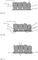
- FIG 1 shows a set of prefabricated prosthetic teeth 2 according to the prior art in a schematic cross-sectional view.
- the prosthetic teeth 2 are suitable for implementing a method according to the invention and for producing a dental prosthesis according to the invention.
- the prosthetic teeth 2 have a coronal side 3, which later form the occlusal surfaces of the finished wax prosthesis and the finished dental prosthesis and which thereby define the occlusal plane of the wax prosthesis and possibly also the dental prosthesis.
- the basal side 4 of the prosthetic teeth 2 opposite the coronal side 3 is used to connect to a prosthetic base (in Figure 1 not to be seen). Since the prosthetic teeth 2 are pre-assembled, their shape and external dimensions are known.
- data sets are preferably available as virtual models 2 ′′ of the prosthetic teeth 2 (see FIG Figure 2 C) ) or a database with the virtual models of a large number of different sets of prosthetic teeth from which the appropriate ones can be selected.
- the Figures 2 and 3 show the sequence of an exemplary method according to the invention for producing a wax prosthesis in six steps as three schematic cross-sectional views arranged one above the other.
- the virtual three-dimensional models 2 ′′ of the prosthetic teeth 2 can be used to calculate a virtual three-dimensional dental prosthesis model 5 ′ (see FIG Figure 2 A) ).
- Suitable prosthetic teeth 2 are selected using a computational method and / or by the user.
- a CAD process is used to use the model of the patient's oral cavity (in the Figures 1 to 7 not shown) the virtual three-dimensional dental prosthesis model 5 'is generated.
- the shape of the mucosa i.e. the gums of the patient's toothless jaw, determines the shape of the support surface of the virtual three-dimensional dental prosthesis model 5 'and matching prosthetic teeth 2 are selected from the known three-dimensional shapes of a large number of previously registered, prefabricated prosthetic teeth 2.
- the selected prosthetic teeth 2 determine the virtual shape of the prosthetic teeth 2 'in the virtual dental prosthesis model 5'.
- the virtual models 2 'of the prosthetic teeth 2 also have a coronal side 3 and a basal side 4.
- the coronal sides 3 later form the occlusal surfaces of the wax prosthesis (see Figure 3 C) ).
- the basal side 4 and the coronal side 3 denote not only the lateral ends, but the entire lateral partial areas of the prosthetic teeth 2 and their virtual models 2 ', 2 ".
- the occlusal plane of the wax prosthesis is thus already defined
- the virtual three-dimensional models 2 'of the prosthetic teeth 2 are arranged in the virtual three-dimensional dental prosthesis model 5' in such a way that a virtual dental prosthesis that matches the oral situation is calculated with a suitable occlusion of the virtual models 2 'of the prosthetic teeth 2.
- the chewing function of the Dentition ie the movement of prosthetic teeth 2 and possibly also of the patient's remaining real teeth, can be simulated in order to adapt the position and orientation of the virtual model 2 'of the prosthetic teeth 2' in the virtual prosthetic base 6 '.
- the virtual three-dimensional dental prosthesis model 5 ' is then computationally converted into a virtual three-dimensional model of the prosthesis base 6' and into a by file splitting disassembled virtual three-dimensional model of the denture teeth 2 '(see Figure 2 B) ).
- the interfaces between the virtual model of the prosthetic base 6 'and the virtual model of the prosthetic teeth 2' with roots 7 'for the prosthetic teeth 2' and with matching tooth sockets are calculated as negatives of the roots 7 'in the virtual model of the prosthetic base 6'.
- 3D data on the shape of the upper side (in all figures at the top) of the virtual three-dimensional model of the prosthesis base 6 ' are stored together with data on the position and location of the virtual three-dimensional prosthetic teeth 2'.
- the tooth sockets required for the unprocessed, prefabricated prosthetic teeth 2 are calculated.
- virtual three-dimensional models 2 ′′ of the unprocessed, prefabricated prosthetic teeth 2 are reproduced in accordance with the position and location of the virtual three-dimensional prosthetic teeth 2 ′ of the virtual three-dimensional dental prosthesis model 5 ′ Figure 2 B) positioned or included in the shape of the top of the virtual three-dimensional model of the prosthesis base 6 '.
- shapes of the basal sides 4 of the virtual three-dimensional models 2 ′′ of the unprocessed, prefabricated prosthetic teeth 2 according to the position and location in the virtual three-dimensional dental prosthesis model 5 ′ are reproduced in the surface Figure 2 B) positioned.
- the 3D data for the shape of the top of the virtual three-dimensional model of the prosthesis base 6 ' are modified in accordance with the basal sides 4 of the three-dimensional virtual models 2 "of the prefabricated prosthetic teeth 2 and a new data set is generated that shows the shape of the top of a prosthetic base 8 of the pretends to be manufactured wax prosthesis.
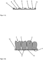
- FIG Figure 3 A A correspondingly preformed blank 8 or a physical prosthesis base 8 as a semi-finished product is shown in FIG Figure 3 A) shown.
- the prosthesis base 8 is made from wax or from a wax-like plastic that can be manually molded at below 80 ° C with the aid of a computer-controlled 3D printer based on the previously generated data set, which specifies the shape of the top of the prosthesis base 8 to be made of the wax prosthesis to be made.
- the top corresponds to the top of the model of the prosthesis base 6 ', while the bottom is made thicker than the model of the prosthesis base 6'.
- the wax or the waxy plastic has a dropping point between 85 ° C and 115 ° C.
- the prosthesis base 8 can also be produced on the basis of the same data set with the aid of a different RP method.
- the prosthesis base 8 four tooth compartments 9 are arranged, starting from the top, which are negatives of the basal sides of the prefabricated prosthetic teeth 2.
- the preformed blank 8 and thus the first only on the top (in Figure 3 A) above) shaped prosthesis base 8 is thicker than the finished prosthesis base 8 according to Figure 3 C) .
- the tooth sockets 9 can also extend through the entire thickness of the prosthesis base 8 and thus form a continuous hole, like that for the tooth socket 9 on the left side of the denture base 8 in Figure 3 A) is indicated.
- the prefabricated denture teeth 2 are adjusted Figure 1 inserted into the prosthesis base 8 and glued there (see Figure 3 B) ). Their location and position in the prosthesis base 8 is clearly predetermined by the shape of the tooth sockets 9. As a result, the occlusal plane of the prosthetic teeth 2 is also clearly specified.
- the wax or the waxy plastic is preferably used as the adhesive.
- the prosthetic teeth 2 rest flush against the tooth sockets 9 on their basal sides 4 or their roots and are held there in a stable manner.
- the bottom of the in Figure 3 B) The wax prosthesis shown and produced does not yet correspond to the dental prosthesis model 5 ' Figure 2 A) .
- the in Figure 3 B) The wax prosthesis shown on the underside is milled off with the computer-controlled 5-axis milling machine.
- the wax prosthesis after Figure 3 B) can be turned around for this.
- both the prosthesis base 8 and all prosthetic teeth 2 on the basal side 4 are processed and the prosthetic teeth 2 are shortened (see Figure 3 C) ).
- the prosthetic teeth 2 on the basal side 4 are shortened to a greater extent than is specified by the data on the surface of the underside of the virtual three-dimensional model of the prosthetic base 6 '. Even a very slight excessive shortening of 0.01 mm can be sufficient if the wax prosthesis was manufactured very carefully and with a high degree of accuracy. According to the invention, however, an excessive shortening of 0.1 mm to 0.5 mm is preferred in order to allow a sufficient manual change in the position and the position of the prosthetic teeth 2 in the prosthetic base 8 without edges of the basal sides 4 of the prosthetic teeth 2 subsequently touching the underside of the wax prosthesis or the underside of the prosthesis base 8 protrude or penetrate through it.
- the wax prosthesis shown according to the invention can thus be tried on on the patient and the position and orientation of individual or all of the prosthetic teeth 2 can be slightly adapted.
- the top of a prosthetic base 10 to be manufactured for the final Dental prosthesis corresponds to the scanned shape, which corresponds to the virtual three-dimensional model of the dental prosthesis Figure 2 A) can be corrected or improved, and the tooth sockets 9, which correspond to the shape of the machined basal sides 4 of the prosthetic teeth 2.
- the underside of the prosthesis base 10 to be produced corresponds to the underside of the virtual three-dimensional model of the dental prosthesis Figure 2 A) or the virtual three-dimensional model of the prosthesis base 6 ' Figure 2 B) .
- the prosthesis base 10 for the final dental prosthesis is milled from this data with the computer-controlled 5-axis milling machine from a blank made of a hard plastic that is colored to match the gums (see FIG Figure 4 A) ).
- a slight excess of cement a special dental adhesive or superglue can be used as the adhesive. Excess cement dough or adhesive residue that bulges out can be removed before and / or after hardening. When calculating the tooth sockets, a glue gap can also be taken into account and provided.
- a self-hardening cement based on powder and liquid is preferably used. The adhesive or the cement can also or additionally be applied to the roots 7 of the prosthetic teeth 2.
- the dental prosthesis can be finalized by polishing and removing adhesive residue.
- a wax or a waxy plastic is smeared into the holes on the underside of the prosthesis base 8.
- this closure 12 can also be printed with a 3D printer, with the data on the underside of the virtual three-dimensional dental prosthesis model 5 'according to this Figure 2 A) or the virtual three-dimensional model of the prosthesis base 6 ' Figure 2 B) be used.
- the closure 12 if it has been applied in excess, can also be processed with the computer-controlled 5-axis milling machine from the underside of the wax prosthesis, according to the data on the underside of the virtual three-dimensional dental prosthesis model 5 ' Figure 2 A) or the virtual three-dimensional model of the prosthesis base 6 ' Figure 2 B) .
- the wax prosthesis shown according to the invention can be fitted to the patient and the position and orientation of at least one prosthetic tooth 2 can be corrected in the process.
- the wax prosthesis shown can be used for adaptation to the patient and the closure 12 can only be generated afterwards.
- the wax prosthesis with the basal closures 12, which has been corrected in the setup of the prosthetic teeth 2, is then poured into a cuvette 14 made of silicone or plaster of paris or gel, as shown in FIG Figure 5 B) is shown. Channels 16 are kept free.
- the wax or the waxy plastic of the prosthesis base 8 is then removed by scalding with water vapor or melting or also chemically by etching away or dissolving.
- the cuvette 14 remains as a hollow shape, as shown in FIG Figure 6 A) is shown.
- the cuvette 14 delimits a cavity 18, the outer shape of which corresponds to the shape of the prosthesis base 20 to be produced.
- the prosthetic teeth 2 remain within the cuvette 14 in the position and position that were determined by the manually modified wax prosthesis Figure 5 A) was specified.
- the basal sides 4 of the processed, prefabricated prosthetic teeth 2 protrude into the cavity 18.
- the cuvette 14 is then poured through the channels 16 with a plastic that is colored to match the gums.
- the plastic hardens in the cavity 18 and forms the prosthetic base 20 of the final dental prosthesis, as shown in FIG Figure 6 B) is shown.
- the basal sides 4 of the prosthetic teeth 2 are embedded in the plastic and connected to it.
- the channels 16 form webs 22 from the hardened plastic, which are arranged on the prosthesis base 20.
- the basal sides 4 of the prosthetic teeth 2 on the underside of the prosthetic base 20 are covered by the plastic of the prosthetic base 20 and are physically held.
- the cuvette 14 is removed and the final dental prosthesis is removed from the mold, as shown in FIG Figure 7 A) is shown.
- the webs 22 are then removed, if necessary the prosthesis base 20 is deburred and the prosthesis base 20 is polished.
- the dental prosthesis is then as it is in Figure 7 B) shown is completed.
- the dental prosthesis produced in this way according to Figure 7 B) thus has the advantage that the position and location of the prosthetic teeth 2 is not influenced by a variable adhesive gap, since the prosthetic teeth 2 are embedded directly in the plastic of the prosthetic base 20.
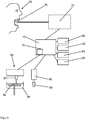
- Figure 8 shows a schematic representation of a device according to the invention for implementing a method according to the invention.
- the device can also be understood as a combination of several interconnected devices.
- the device comprises a computer 72 which is suitably programmed to implement the essential steps of a method according to the invention as a controller.
- the computer 72 has an electronic data memory 73 to which the computer 72 has access and in which the virtual three-dimensional models for implementing the method are stored or can be stored and temporarily stored.
- the virtual three-dimensional shapes 2 ′′ of different sets of prefabricated prosthetic teeth 2 can be stored in the data memory 73, so that these data records can be accessed with the program for implementing the method in order to calculate the virtual three-dimensional dental prosthesis model 5 ′ that the data of these shapes of the prosthetic teeth 2 (in particular their coronal sides 3 and cervical sides 4) are included.
- the computer 72 is connected to an intraoral scanner 74.
- the intraoral scanner 74 comprises a scanner head 76 which can be inserted into the oral cavity of a patient 78 in order to record the oral cavity situation in the patient 78.
- the intraoral scanner 74 thus scans the surface of the mucosa and any teeth of the patient 78 that may be present.
- These data can be stored in the data memory 73 of the computer 72 as a virtual three-dimensional model of the oral situation of the patient 78.
- the virtual three-dimensional dental prosthesis model 5 ′ is calculated with the aid of a dental prosthesis calculation module 80.
- the device further comprises a tooth socket module 82 for calculating the tooth sockets 9 in the upper side of the virtual three-dimensional model of the prosthesis base 6 'from at least one virtual three-dimensional model 2 "of the unprocessed, prefabricated prosthetic teeth 2.
- the virtual three-dimensional dental prosthesis model 5' calculated in this way. is used with the help of a file splitting module 84 for the computational separation of the virtual three-dimensional dental prosthesis model 5 'into the virtual three-dimensional model of the prosthesis base 6' and the virtual three-dimensional model 2 ' the denture teeth 2 separated.
- the intermediate results are temporarily stored in the data memory 73.
- the device further comprises a shortening module 85 with which the basal shape of the shortened prosthetic teeth 2 is calculated.
- the basal sides 4 of the prosthetic teeth 2 are calculated as virtual three-dimensional models in such a way that the basal sides 4 of the prosthetic teeth 2 from the underside of the virtual three-dimensional model of the prosthetic base 6 'with a fixed distance of at least 0.01 mm or of at least 0, 05 mm or a distance between 0.1 mm and 0.5 mm.
- the shortening module 85 uses the calculations of the shortening module 85, the unprocessed, prefabricated prosthetic teeth 2 inserted into the tooth sockets 9 of the preformed prosthesis base 8 are shortened on the basal side 4.
- a first CAM-controlled 3D printer 88 is controlled by the computer 72.
- the tooth sockets 9 are worked into a blank or a round blank in accordance with the calculations of the tooth socket module 82, so that the prosthesis base 8 is created therefrom (see FIG Figure 3 A) ).
- the 3D printer 88 has a printer head 92, a wax or plastic bath 96 and an object table 94 that can be lowered (or raised) in the wax or plastic bath 96, so that the preformed blank 8 can be produced on the object table 94 .
- Other types of 3D printers such as those that use powders and squeegees to apply even layers, can also be used without further ado.
- a CAM-controlled 5-axis milling machine 86 with a milling head 90 is controlled by the computer 72 for the basal and cervical machining or shortening of the prosthetic teeth 2, that is, for the shaping of the basal sides 4 on the physical prosthetic teeth 2.
- the unprocessed denture teeth 2 (see Figure 3 B) ) processed cervically on the basal side 4 and carved out the basal sides 4 according to the virtual three-dimensional model of the basal sides 4 of the prosthetic teeth 2 according to the calculations of the shortening module 85 (see Figure 3 C) ).
- a different CAM-controlled 5-axis milling cutter 88 can also be used for machining or shortening the prosthetic teeth 2 than for machining the underside of the preformed blank 8.
- the virtual three-dimensional 2 ′′ model of the prefabricated prosthetic teeth 2 can consist of a plurality of individual virtual three-dimensional models 2 ′′ of the prosthetic teeth 2. A separate virtual three-dimensional model can exist for each individual prosthetic tooth 2. The total of these individual virtual three-dimensional models then results in the virtual three-dimensional model 2 ′′ of the prosthetic teeth 2.
Landscapes
- Health & Medical Sciences (AREA)
- Oral & Maxillofacial Surgery (AREA)
- Dentistry (AREA)
- Epidemiology (AREA)
- Life Sciences & Earth Sciences (AREA)
- Animal Behavior & Ethology (AREA)
- General Health & Medical Sciences (AREA)
- Public Health (AREA)
- Veterinary Medicine (AREA)
- Engineering & Computer Science (AREA)
- Manufacturing & Machinery (AREA)
- Dental Prosthetics (AREA)
Description
Die Erfindung betrifft ein Verfahren zur Herstellung einer Wachsprothese, wobei die Wachsprothese eine Prothesenbasis und mehrere Prothesenzähne aufweist, wobei das Verfahren unter Anwendung eines virtuellen dreidimensionalen Dentalprothesen-Modells der zu erzeugenden physischen Dentalprothese erfolgt.The invention relates to a method for producing a wax prosthesis, the wax prosthesis having a prosthesis base and several prosthetic teeth, the method being carried out using a virtual three-dimensional dental prosthesis model of the physical dental prosthesis to be produced.
Die Erfindung betrifft auch eine Wachsprothese und eine Dentalprothese hergestellt mit einem solchen Verfahren und eine Vorrichtung zum Durchführen eines solchen Verfahrens.The invention also relates to a wax prosthesis and a dental prosthesis produced using such a method and a device for carrying out such a method.
Der derzeit gängige Weg ist die analoge Erstellung von Dentalprothesen. Zur Herstellung der Prothesenbasis wird dazu derzeit meist ein analoges Verfahren verwendet, bei dem zunächst ein Abdruck des zahnlosen Kiefers des Patienten genommen wird. Aus diesem Abdruck wird ein Gipsmodell der Patientensituation gefertigt.The currently common way is the analog creation of dental prostheses. To manufacture the prosthesis base, an analogous process is currently used, in which an impression of the patient's toothless jaw is first taken. A plaster model of the patient's situation is made from this impression.
Zur Herstellung der Dentalprothese werden Prothesenzähne manuell und einzeln auf einer Wachsbasis auf dem Gipsmodell des unbezahnten Kiefers aufgestellt. Bei der Aufstellung der vorkonfektionierten Prothesenzähne werden diese der jeweiligen Mundsituation des Patienten vom Zahntechniker angepasst und gegebenenfalls auch vom Zahnarzt bei der Einprobe korrigiert.To produce the dental prosthesis, prosthetic teeth are set up manually and individually on a wax base on the plaster model of the edentulous jaw. When the prefabricated denture teeth are set up, the dental technician adjusts them to the respective oral situation of the patient and, if necessary, corrects them by the dentist during the try-in.
Diese Wachsprothese wird im nächsten Schritt in einer Küvette mit Gips, Silikon oder Gel (je nach späterer Verarbeitungstechnik) eingebettet, um dann nach Aushärten des Einbettmaterials die Wachsbasis aus der Form heraus zu lösen, um einen Hohlraum für den Prothesenkunststoff zu schaffen. Die Prothesenzähne verbleiben dabei meist im Einbettmaterial, also in der Küvette. Ein entsprechender Kunststoff wird in den Hohlraum injiziert oder gegossen, dadurch erhält man nach der Aushärtung des Kunststoffs die Dentalprothese. Nach Aushärtung des Kunststoffs wird dieser nachbearbeitet, um die gewünschte Oberflächengüte zu erhalten.In the next step, this wax prosthesis is embedded in a flask with plaster of paris, silicone or gel (depending on the later processing technique), and then after the investment material has hardened, the wax base is released from the mold to create a cavity for the prosthetic plastic. The denture teeth usually remain in the embedding material, i.e. in the flask. A corresponding plastic is injected or poured into the cavity, thereby obtaining the dental prosthesis after the plastic has hardened. After the plastic has hardened, it is reworked in order to obtain the desired surface quality.
Neben handwerklichen Techniken gewinnen digitale Fertigungsmethoden im Dentalbereich immer mehr an Bedeutung. Zahnersatz, wie zum Beispiel Kronen und Brücken, wird seit einigen Jahren mittels CAD/CAM-Technologien subtraktiv in Fräsverfahren hergestellt (CAM - Computer-Aided Manufacturing, Deutsch: rechnerunterstützte Fertigung, CAD - Computer-Aided Design, Deutsch: rechnerunterstützte Konstruktion).In addition to manual techniques, digital manufacturing methods are becoming increasingly important in the dental sector. Dental prostheses, such as crowns and bridges, have been manufactured subtractively in milling processes using CAD / CAM technologies (CAM - Computer-Aided Manufacturing, German: computer-aided production, CAD - Computer-Aided Design, German: computer-aided design).
Ein CAD/CAM-Verfahren zur Herstellung einer Dentalprothese ist aus der
Ferner gewinnen generative CAM-Verfahren wie SLM (Selective Laser Melting) zur Herstellung von Kronen, Brücken und Modellen sowie Stereolithographie und DLP (Digital light processing) für Dentalprodukte auf Polymerbasis wie zum Beispiel Provisorien, Prothesen, KFO-Apparaturen (Kiefer-Orthopädie-Apparaturen), Aufbissschienen, Bohrschablonen oder Dentalmodellen immer mehr an Bedeutung. Dabei ist die Herstellung von Zahnersatz auf Acrylatbasis mittels RP-Verfahren (Rapid-Prototyping-Verfahren) bisher immer noch starken Einschränkungen unterworfen. Mehrfarbiger Zahnersatz oder Zahnersatz aus verschiedenen Polymer-Materialien (zum Beispiel für Schmelz- und Dentinmassen) zur Herstellung von hochwertigem und ästhetischem Zahnersatz ist bisher nur mittels aufwendiger RP-Maschinen mit mehreren Materialkammern oder mittels Klebe- und Fügetechniken herstellbar.Generative CAM processes such as SLM (Selective Laser Melting) for the production of crowns, bridges and models as well as stereolithography and DLP (digital light processing) for polymer-based dental products such as temporaries, prostheses, orthodontic appliances (jaw orthopedic appliances) are also gaining ground ), Occlusal splints, drilling templates or dental models are becoming more and more important. The manufacture of dentures based on acrylate using the RP process (rapid prototyping process) is still subject to severe restrictions. Multi-colored dentures or dentures made of different polymer materials (for example for enamel and dentin materials) for the production of high-quality and aesthetic dentures can only be produced using complex RP machines with several material chambers or using adhesive and joining techniques.
Ebenso ist die Herstellung von Materialkombinationen (zum Beispiel Legierungen und Polymere) mittels RP-Verfahren bisher sehr aufwendig und bisher nicht in Serienreife umgesetzt. Die generative Herstellung von ästhetisch anspruchsvollen Konfektionszähnen für Teil- oder Totalprothesen ist derzeit nicht möglich, da mittels Stereolithographie nur ein Material beziehungsweise eine Farbe gedruckt werden kann. Das Drucken von mehrfarbigen Konfektionszähnen ist derzeit nicht möglich. Aus diesem Grund wird die Prothesenbasis mittels CAM-Verfahren (beispielsweise Fräsen oder Drucken) hergestellt und vorkonfektionierte Prothesenzähne werden mit der Prothesenbasis verklebt. Hierbei kann die Prothesenbasis sowohl durch generative Verfahren (SLA, DLP, FDM, etc.) als auch durch subtraktive Verfahren (Fräsen und dergleichen) hergestellt werden. Die künstlichen Prothesenzähne können sowohl als Einzelzähne als auch als komplette Zahnreihen hergestellt und mit der Prothese verklebt werden.Likewise, the production of material combinations (for example alloys and polymers) using the RP process has so far been very complex and has not yet been implemented in series production. The generative production of aesthetically sophisticated prefabricated teeth for partial or full dentures is currently not possible, since only one material or one color can be printed using stereolithography. It is currently not possible to print multi-colored prefabricated teeth. For this reason, the denture base is manufactured using CAM processes (e.g. milling or printing) and pre-assembled denture teeth are glued to the denture base. Here, the prosthesis base can be produced both by generative processes (SLA, DLP, FDM, etc.) and by subtractive processes (milling and the like). The artificial denture teeth can be produced as individual teeth or as complete rows of teeth and glued to the denture.
Es gibt bereits erste Verfahren, wie beispielsweise die aus der
Bei der Herstellung von herausnehmbarem Zahnersatz, wie Voll- und Teilprothesen, die mit Hilfe digitaler Daten mit einer CAD-Konstruktion gefertigt wurden, gibt es technische Lösungsansätze, die Daten der Prothesenbasis und der Zähne zu separieren. Die Prothesenbasis kann dabei durch ein generatives oder auch subtraktives Fertigungsverfahren hergestellt werden. Als Prothesenzähne kommen konfektionierte Kunststoffzähne oder auch individuell hergestellte Prothesenzähne oder Zahnbögen aus den gleichen Ausgangsmaterialien in Frage. In jedem Fall müssen an der Prothesenbasis Zahnfächer zur Aufnahme dieser Prothesenzähne vorgesehen sein, in welche dann in einem nachgeschalteten manuellen Fertigungsschritt, die Prothesenzähne oder die Zahnbögen, zum Beispiel durch Kleben, befestigt werden.In the production of removable dentures, such as full and partial dentures, which were manufactured with the help of digital data with a CAD design, there are technical approaches to separate the data of the denture base and the teeth. The prosthesis base can be manufactured using a generative or subtractive manufacturing process. Prefabricated plastic teeth or individually manufactured prosthetic teeth or dental arches made from the same starting materials can be used as prosthetic teeth. In any case, tooth sockets for receiving these prosthetic teeth must be provided on the prosthetic base, in which the prosthetic teeth or the dental arches are then attached, for example by gluing, in a subsequent manual production step.
Aus der
Diese Verfahren haben den Nachteil, dass die Prothesenzähne einzeln in die Prothesenbasis eingesetzt und eingeklebt werden müssen und dabei Verwechslungen vorkommen können. Der richtige Ort zum Einsetzen der bearbeiteten Prothesenzähne in die Prothesenbasis muss dabei durch Ausprobieren gefunden werden. Die passende basale Form der Prothesenzähne muss für jeden Prothesenzahn individuell berechnet werden. Bei solchen Verfahren kann es zu Fehlsetzungen von Prothesenzähnen in der Prothesenbasis kommen oder diese Fehlsetzungen müssen mit zusätzlichen Maßnahmen verhindert werden. Bei der Verwendung von industriell gefertigten (und daher vorkonfektionierten) einzelnen Prothesenzähnen müssen diese in der Regel vor dem Verkleben basal gekürzt werden, um die Bisshöhe einzustellen beziehungsweise um mit der herzustellenden Dentalprothese eine optimale Okklusion zu erreichen.These methods have the disadvantage that the denture teeth have to be individually inserted and glued into the denture base, which can lead to mix-ups. The right place to insert the processed denture teeth into the denture base must be found by trial and error. The appropriate basal shape of the denture teeth must be calculated individually for each denture tooth. Such procedures can lead to incorrect setting of denture teeth in the denture base or these incorrect setting must be prevented with additional measures. When using industrially manufactured (and therefore prefabricated) individual denture teeth, they usually have to be shortened at the base before gluing in order to adjust the bite height or to achieve optimal occlusion with the dental prosthesis to be produced.
Nachteilig ist bei den bisherigen Verfahren auch, dass beim Einkleben der Prothesenzähne Abweichungen in der Bisshöhe (der Okklusion) im Vergleich zu dem digitalen Modell auftreten können, da die Materialstärke des Klebstoffs zwischen den Prothesenzähnen und der Prothesenbasis nicht genau vorhergesagt werden kann. Dadurch müssen die Prothesenzähne anschließend okklusal nachgeschliffen und anschließend poliert werden. Zudem können durch eine ungleichmäßige Verteilung des Klebstoffs zwischen den Prothesenzähnen und der Prothesenbasis ungleichmäßige mechanische Eigenschaften entstehen, so dass die Stabilität der Dentalprothese nicht gleichmäßig ist. Des Weiteren kann es zu leichten Abweichungen in der Lage und Orientierung der Prothesenzähne in der Prothesenbasis im Vergleich zu dem virtuellen Dentalprothesen-Modell und in der Wachseinbettung kommen, die aufgrund von notwendigen Fertigungstoleranzen auftreten. Ferner kann es passieren, dass Prothesenzähne an den falschen Positionen in die Prothesenbasis eingesetzt werden.The previous methods also have the disadvantage that when the denture teeth are glued in, deviations in the bite height (occlusion) compared to the digital model can occur, since the material thickness of the adhesive between the denture teeth and the denture base cannot be precisely predicted. As a result, the denture teeth then have to be reground occlusally and then polished. In addition, uneven distribution of the adhesive between the denture teeth and the denture base can result in non-uniform mechanical properties, so that the stability of the dental prosthesis is not uniform. Furthermore, there may be slight deviations in the position and orientation of the prosthetic teeth in the prosthesis base compared to the virtual dental prosthesis model and in the wax embedding, which occur due to the necessary manufacturing tolerances. It can also happen that denture teeth are inserted in the wrong positions in the denture base.
Aus der
Solche Verfahren haben ferner den Nachteil, dass insbesondere vorkonfektionierte Prothesenzähne oft okklusal und/oder basal nachbearbeitet werden müssen, wobei anschließend auch die Zahnfächer der Prothesenbasis beschliffen werden, um die Position und Lage der Prothesenzähne in der Dentalprothese anzupassen. In den meisten Fällen müssen bei vorkonfektionierten Prothesenzähnen, die die besten ästhetischen Ergebnisse liefern, diese vor dem Verkleben zumindest basal eingekürzt werden, um die Bisshöhe (die Okklusion) der Dentalprothese einzustellen, so dass sich die Notwendigkeit ergibt, hierzu ein rationelles und kostengünstiges Verfahren anzugeben.Such methods also have the disadvantage that, in particular, prefabricated prosthetic teeth often have to be reworked occlusally and / or basally, with the tooth sockets of the prosthetic base then also being ground in order to adapt the position of the prosthetic teeth in the dental prosthesis. In most cases, prefabricated denture teeth that provide the best aesthetic results have to be shortened at least at the base before bonding in order to adjust the bite height (the occlusion) of the dental prosthesis, so that it is necessary to provide a rational and cost-effective method for this purpose .
Bei der Herstellung von hochwertigen und hochästhetischen Dentalprothesen unter Verwendung von solchen vorkonfektionierten Prothesenzähnen und einer mittels CAD/CAM-Verfahren gefertigten Prothesenbasis müssen die Prothesenzähne und die Prothesenbasis miteinander dauerhaft und kostengünstig verbunden werden. Das Verbinden der Prothesenzähne mit der Prothesenbasis soll daher möglichst leicht, unaufwendig und in wenigen Schritten erfolgen können. Da die Zahnfächer der Prothesenbasis meist nicht sehr tief angelegt werden können, haben die eingesetzten Prothesenzähne häufig nicht genug Führung, so dass eine Rotations- und auch Kippbewegung in oraler beziehungsweise lingualer Richtung jedes einzelnen Prothesenzahnes aber auch der Prothesenzähne zueinander, die Dentalzwischenräume betreffend, möglich ist. Die Positionierung und nachträgliche Korrektur der Prothesenzähne verwässert daher die Vorteile einer optimalen CAD-konstruierten Aufstellung und Abstimmung der Prothesenzähne in den Prothesenbasen für Ober- und Unterkiefer teilweise.In the production of high-quality and highly aesthetic dental prostheses using such prefabricated prosthetic teeth and one using CAD / CAM processes manufactured prosthetic base, the prosthetic teeth and the prosthetic base must be connected to one another permanently and inexpensively. The connection of the denture teeth to the denture base should therefore be as easy, inexpensive as possible and be able to take place in just a few steps. Since the tooth sockets of the denture base usually cannot be placed very deeply, the inserted denture teeth often do not have enough guidance, so that a rotational and tilting movement in the oral or lingual direction of each individual denture tooth but also of the denture teeth in relation to the dental gaps is possible . The positioning and subsequent correction of the denture teeth therefore partially dilutes the advantages of an optimal CAD-constructed setup and coordination of the denture teeth in the denture bases for the upper and lower jaw.
Die Aufgabe der Erfindung besteht also darin, die Nachteile des Stands der Technik zu überwinden. Insbesondere soll ein Verfahren bereitgestellt werden, mit dem eine einfache, für Fehler unanfällige und mit exakter Bisshöhe (Okklusion) eingestellte Herstellung der Dentalprothese durchführbar ist, sowie eine Vorrichtung bereitzustellen mit der die wesentlichen Verfahrensschritte umsetzbar sind. Dabei sollen moderne computergesteuerte Verfahren einsetzbar sein und vorhandene Daten und Techniken möglichst weitreichend nutzbar sein. Gleichzeitig soll eine geringfügige manuelle Korrektur der Lage und Position möglich sein und eine okklusale Bearbeitung der Prothesenzähne möglichst vermieden werden. Zudem sollen die Prothesenzähne möglichst ohne eine Fehlsetzung und mit möglichst geringen Abweichungen in der zuvor berechneten Orientierung und Lage an der Prothesenbasis befestigt werden können. Die fertige Dentalprothese soll möglichst ohne weitere Nachbearbeitung oder mit möglichst wenig manueller Nachbearbeitung einsatzbereit sein. Die Lage und Ausrichtung der Prothesenzähne in den Zahnfächern der Prothesenbasis sollen möglichst leicht und exakt einstellbar sein. Die bearbeiteten Prothesenzähne sollen dabei stabil in der Prothesenbasis gehalten werden können. Dabei soll möglichst auch eine Stabilisierung der Prothesenzähne an den basalen Seiten der Prothesenzähne durch die Prothesenbasis erfolgen.The object of the invention is therefore to overcome the disadvantages of the prior art. In particular, a method is to be provided with which a simple production of the dental prosthesis can be carried out that is not susceptible to errors and with an exact bite height (occlusion), as well as providing a device with which the essential method steps can be implemented. It should be possible to use modern computer-controlled processes and existing data and technologies should be able to be used as widely as possible. At the same time, a slight manual correction of the position and position should be possible and occlusal processing of the prosthetic teeth should be avoided as far as possible. In addition, the denture teeth should be able to be attached to the denture base without any misalignment and with the lowest possible deviations in the previously calculated orientation and position. The finished dental prosthesis should be ready for use without further post-processing or with as little manual post-processing as possible. The position and alignment of the denture teeth in the tooth sockets of the denture base should be adjustable as easily and precisely as possible. The processed denture teeth should be able to be held stable in the denture base. If possible, the prosthetic teeth should also be stabilized on the basal sides of the prosthetic teeth by the prosthetic base.
Die Aufgaben der Erfindung werden gelöst durch ein Verfahren zur Herstellung einer Wachsprothese, wobei die Wachsprothese eine Prothesenbasis und mehrere basal bearbeitete vorkonfektionierte Prothesenzähne aufweist und wobei das Verfahren unter Verwendung eines virtuellen dreidimensionalen Dentalprothesen-Modells durchgeführt wird, wobei das Verfahren die folgenden Schritte umfasst:
- A) Teilen des virtuellen dreidimensionalen Dentalprothesen-Modells der herzustellenden physischen Wachsprothese in zumindest ein virtuelles dreidimensionales Modell der Prothesenzähne und ein virtuelles dreidimensionales Modell der Prothesenbasis oder Verwenden zumindest eines vorhandenen virtuellen dreidimensionalen Modells der Prothesenzähne und eines vorhandenen virtuellen dreidimensionalen Modells der Prothesenbasis,
- B) Herstellen eines vorgeformten Rohlings aus Wachs oder aus einem bei unter 80°C manuell formbaren, wachsartigen Kunststoff mit einer generativen ersten CAM-Vorrichtung entsprechend den Daten der Oberseite des virtuellen dreidimensionalen Modells der Prothesenbasis, wobei entweder
- C1) nach der Herstellung des vorgeformten Rohlings mit einer subtraktiven zweiten CAM-Vorrichtung in der Oberseite des vorgeformten Rohlings mehrere Zahnfächer erzeugt werden oder
- C2) während der Herstellung des vorgeformten Rohlings mit der additiven ersten CAM-Vorrichtung in der Oberseite des vorgeformten Rohlings mehrere Zahnfächer erzeugt werden, wobei für jeden gemäß dem virtuellen dreidimensionalen Dentalprothesen-Modell einzusetzenden vorkonfektionierten Prothesenzahn ein Zahnfach in dem vorgeformten Rohling erzeugt wird,
- D) Einsetzen und Befestigen der unbearbeiteten vorkonfektionierten Prothesenzähne in die jeweiligen Zahnfächer des vorgeformten Rohlings,
- E) Kürzen der basalen Seiten der in dem vorgeformten Rohling befestigten vorkonfektionierten Prothesenzähne mit der subtraktiven zweiten CAM-Vorrichtung oder einer subtraktiven dritten CAM-Vorrichtung nach Maßgabe der Daten zur Unterseite des virtuellen dreidimensionalen Modells der Prothesenbasis, wobei die vorkonfektionierten Prothesenzähne stärker gekürzt werden, als es die Daten zur Unterseite des virtuellen dreidimensionalen Modells der Prothesenbasis vorgeben,
- F) Subtraktives Bearbeiten der Unterseite des vorgeformten Rohlings mit der subtraktiven zweiten CAM-Vorrichtung oder der subtraktiven dritten CAM-Vorrichtung oder einer subtraktiven vierten CAM-Vorrichtung entsprechend den Daten der Unterseite des virtuellen dreidimensionalen Modells der Prothesenbasis.
- A) Splitting the virtual three-dimensional dental prosthesis model of the physical wax prosthesis to be produced into at least one virtual three-dimensional model of the prosthetic teeth and a virtual three-dimensional model of the prosthesis base or using at least one existing virtual three-dimensional model of the Denture teeth and an existing virtual three-dimensional model of the denture base,
- B) Production of a preformed blank from wax or from a waxy plastic that can be manually molded at below 80 ° C. using a generative first CAM device in accordance with the data on the upper side of the virtual three-dimensional model of the prosthesis base, with either
- C1) after the production of the preformed blank with a subtractive second CAM device in the upper side of the preformed blank, or
- C2) during the production of the preformed blank with the additive first CAM device in the upper side of the preformed blank, several tooth compartments are generated, a tooth compartment being generated in the preformed blank for each prefabricated prosthetic tooth to be inserted according to the virtual three-dimensional dental prosthesis model,
- D) Insertion and attachment of the unprocessed, prefabricated denture teeth in the respective tooth sockets of the preformed blank,
- E) Shortening the basal sides of the prefabricated prosthetic teeth fastened in the preformed blank with the subtractive second CAM device or a subtractive third CAM device in accordance with the data on the underside of the virtual three-dimensional model of the prosthesis base, the prefabricated prosthetic teeth being shortened more than it specifies the data on the underside of the virtual three-dimensional model of the prosthesis base,
- F) Subtractive processing of the underside of the preformed blank with the subtractive second CAM device or the subtractive third CAM device or a subtractive fourth CAM device in accordance with the data of the underside of the virtual three-dimensional model of the prosthesis base.
Die Oberseite der Prothesenbasis und damit des virtuellen dreidimensionalen Modells der Prothesenbasis ist die Seite, die der zur Auflage auf dem zahnlosen Kiefer beziehungsweise dem Zahnfleisch vorgesehenen Unterseite gegenüberliegt. Die Richtungsbezeichnungen lassen sich auch auf den Rohling anwenden, sobald er zumindest bereichsweise bearbeitet ist. Für die virtuellen dreidimensionalen Modelle werden die gleichen Richtungsbezeichnungen entsprechend analog angewendet.The top of the prosthesis base and thus of the virtual three-dimensional model of the prosthesis base is the side that is opposite the underside provided for resting on the toothless jaw or the gums. The directional designations can also be used on the blank as soon as it has been processed at least in certain areas. For the virtual three-dimensional models, the same directional designations are used in an analogous manner.
Bevorzugt kann erfindungsgemäß vorgesehen sein, dass alle subtraktiven Bearbeitungen mit der zweiten CAM-Vorrichtung durchgeführt werden, vorzugsweise alle subtraktiven Bearbeitungen und das Kürzen der basalen Seiten der vorkonfektionierten Prothesenzähne mit der zweiten CAM-Vorrichtung durchgeführt werden.According to the invention, it can preferably be provided that all subtractive processing is carried out with the second CAM device, preferably all subtractive processing and the shortening of the basal sides of the prefabricated prosthetic teeth are carried out with the second CAM device.
Gemäß einer bevorzugten Ausführung des erfindungsgemäßen Verfahrens kann vorgesehen sein, dass in Schritt C1) oder C2) die Zahnfächer derart tief erzeugt werden, dass jeder unbearbeitete vorkonfektionierte Prothesenzahn derart in das jeweilige Zahnfach einsetzbar ist, dass die Okklusionsebene der eingesetzten vorkonfektionierten Prothesenzähne der Okklusionsebene des virtuellen dreidimensionalen Dentalprothesen-Modells entspricht.According to a preferred embodiment of the method according to the invention, it can be provided that in step C1) or C2) the tooth sockets are generated so deep that each unprocessed prefabricated prosthetic tooth can be inserted into the respective tooth socket in such a way that the occlusal plane of the prefabricated prosthetic teeth used corresponds to the occlusal plane of the virtual corresponds to three-dimensional dental prosthesis model.
Hierdurch wird sichergestellt, dass die rechnerisch vorgesehene Okklusion eingehalten wird und so die Wachsprothese die Prothesenzähne in einer Position hält, die für ein Zusammenwirken der Prothesenzähne optimiert ist.This ensures that the computationally provided occlusion is maintained and the wax prosthesis thus holds the prosthetic teeth in a position that is optimized for the interaction of the prosthetic teeth.
Die Prothesenbasis ist nicht Teil der Prothesenzähne. Unter einer Prothesenbasis ist der Teile einer dentalen Teilprothese oder Vollprothese zu verstehen, der einer Nachbildung der Gingiva entspricht und in dem die Prothesenzähne befestigt werden.The denture base is not part of the denture teeth. A prosthesis base is to be understood as the part of a partial or full dental prosthesis that corresponds to a replica of the gingiva and in which the prosthetic teeth are attached.
Das Verfahren soll bevorzugt kein Verfahren zur Behandlung eines menschlichen Körpers sein. Bevorzugt ist eine Behandlung des menschlichen Körpers ausgeschlossen. Selbstverständlich kann eine mit dem Verfahren hergestellte Wachsprothese zur nachfolgenden Herstellung einer Dentalprothese verwendet werden und diese nachfolgend bei einem Patienten eingesetzt werden. Das erfindungsgemäße Verfahren beansprucht jedoch kein Einsetzen bei einem Patienten und keine Anwendung an einem Patienten und erfolgt vollständig außerhalb des Körpers.The method should preferably not be a method for treating a human body. Treatment of the human body is preferably excluded. Of course, a wax prosthesis produced using the method can be used for the subsequent production of a dental prosthesis and this can then be used on a patient. The method according to the invention, however, does not claim to be inserted into a patient or applied to a patient and is carried out entirely outside of the body.
Es kann vorgesehen sein, dass das virtuelle dreidimensionale Dentalprothesen-Modell in Schritt A) rechnerisch mittels File-Splitting in das virtuelle dreidimensionale Modell der Prothesenzähne und das virtuelle dreidimensionale Modell der Prothesenbasis getrennt wird.It can be provided that the virtual three-dimensional dental prosthesis model in step A) is computationally separated into the virtual three-dimensional model of the prosthetic teeth and the virtual three-dimensional model of the prosthetic base by means of file splitting.
Dass die Zahnfächer derart tief ausgeführt werden, so dass jeder unbearbeitete vorkonfektionierte Prothesenzahn derart in das jeweilige Zahnfach einsetzbar ist, dass die Okklusionsebene der eingesetzten vorkonfektionierten Prothesenzähne der Okklusionsebene des virtuellen dreidimensionalen Dentalprothesen-Modells entspricht, kann auch dadurch erreicht werden, dass in dem vorgeformten Rohling durchgehende Ausnehmungen erzeugt werden, die bis zur Unterseite des Rohlings reichen, so dass die Wurzeln, also die basalen Seiten der unbearbeiteten vorkonfektionierten Prothesenzähne an der Unterseite des Rohlings heraustreten oder zu sehen sind, wenn sie in Schritt D) in die Zahnfächer des vorgeformten Rohlings eingesetzt sind. Damit die Prothesenzähne auch dann noch in der gewünschten Okklusionsebene liegen, müssen die Wurzeln der vorkonfektionierten Prothesenzähne konisch geformt sein oder es müssen an den vorkonfektionierten Prothesenzähnen geeignete Absätze oder Vorsprünge vorgesehen sein, damit die vorkonfektionierten Prothesenzähne nicht durch die durchgehenden Zahnfächer nach unten rutschen können.The fact that the tooth sockets are designed so deep that each unprocessed, prefabricated prosthetic tooth can be inserted into the respective tooth socket in such a way that the occlusal plane of the prefabricated prosthetic teeth used corresponds to the occlusal plane of the virtual three-dimensional dental prosthesis model can also be achieved by inserting in the preformed blank Continuous recesses are created that extend to the underside of the blank, so that the roots, i.e. the basal sides of the unprocessed, prefabricated denture teeth emerge on the underside of the blank or can be seen when they are inserted into the tooth sockets of the preformed blank in step D) are. So that the prosthetic teeth still lie in the desired occlusal plane, the roots of the prefabricated prosthetic teeth must be conically shaped or suitable shoulders or projections must be provided on the prefabricated denture teeth so that the prefabricated prosthetic teeth cannot slip down through the continuous tooth sockets.
Die vorkonfektionierten Prothesenzähne bestehen nicht aus Wachs oder aus einem wachsartigen Kunststoff, sondern aus einem harten Material, vorzugsweise aus einem harten Kunststoff oder aus einer Keramik, besonders bevorzugt aus einem polymerisierten Polymethylmethacrylat. In dem Kunststoff können Keramikpartikel enthalten sein.The prefabricated prosthetic teeth are not made of wax or a wax-like plastic, but of a hard material, preferably a hard one Plastic or a ceramic, particularly preferably a polymerized polymethyl methacrylate. Ceramic particles can be contained in the plastic.
Es kann erfindungsgemäß vorgesehen sein, dass die generative erste CAM-Vorrichtung ein computergesteuerter 3D-Drucker ist und/oder
die subtraktive zweite CAM-Vorrichtung, die subtraktive dritte CAM-Vorrichtung oder die subtraktive vierte CAM-Vorrichtung eine computergesteuerte Fräse ist, insbesondere eine Fräse mit mindestens 5 Achsen, oder die zweite und gegebenenfalls die dritte und die vierte CAM-Vorrichtung computergesteuerte Fräsen sind, insbesondere mindestens 5-Achs-Fräsen, wobei das subtraktive Bearbeiten des Rohlings in Schritt F) und gegebenenfalls in Schritt C1) sowie das Kürzen der basalen Seiten der vorkonfektionierten Prothesenzähne in Schritt E) durch Fräsen erfolgen.According to the invention, it can be provided that the generative first CAM device is and / or a computer-controlled 3D printer
the subtractive second CAM device, the subtractive third CAM device or the subtractive fourth CAM device is a computer-controlled milling machine, in particular a milling machine with at least 5 axes, or the second and possibly the third and fourth CAM device are computer-controlled milling machines, in particular at least 5-axis milling, the subtractive machining of the blank in step F) and possibly in step C1) as well as the shortening of the basal sides of the prefabricated prosthetic teeth in step E) by milling.
Die Verwendung eines 3D-Druckers zur Herstellung des vorgeformten Rohlings für die Prothesenbasis ist vorteilhaft, weil dieser günstiger in der Fertigung ist als Fräsen oder andere subtraktive Fertigungsverfahren. Ferner entsteht weniger Abfall.The use of a 3D printer to produce the preformed blank for the prosthesis base is advantageous because it is cheaper to manufacture than milling or other subtractive manufacturing processes. There is also less waste.
Computergesteuerte Fräsen und mindestens 5-Achs-Fräsen sind besonders gut zur Umsetzung des erfindungsgemäßen Verfahrens geeignet. Zudem lassen sich damit die Bearbeitungsschritte auf einfache Weise relativ kostengünstig umsetzen. Ferner sind derartige Fräsen auch bereits in vielen Dentallabors vorhanden und dadurch einsetzbar. Alternativ könnte auch ein Laser oder eine computergesteuerte Schneidvorrichtung zum subtraktiven Bearbeiten und Kürzen verwendet werden.Computer-controlled milling and at least 5-axis milling are particularly suitable for implementing the method according to the invention. In addition, the processing steps can be implemented relatively inexpensively in a simple manner. Furthermore, such milling cutters are already available in many dental laboratories and can therefore be used. Alternatively, a laser or a computer-controlled cutting device could also be used for subtractive processing and shortening.
Dabei kann vorgesehen sein, dass zumindest die erste die computergesteuerte Fräse einen Anstellwinkel von mehr als 25° aufweist, insbesondere einen Anstellwinkel von zumindest 30°, wobei vorzugsweise alle verwendeten computergesteuerten Fräsen einen Anstellwinkel von mehr als 25° aufweisen, insbesondere einen Anstellwinkel von zumindest 30°.It can be provided that at least the first computer-controlled milling cutter has an angle of attack of more than 25 °, in particular an angle of attack of at least 30 °, with all computer-controlled milling cutters used preferably having an angle of attack of more than 25 °, in particular an angle of attack of at least 30 ° °.
Hierdurch kann der Rohling und bevorzugt auch die basalen Enden der Prothesenzähne besonders effizient, schnell und präzise bearbeitet werden.As a result, the blank and preferably also the basal ends of the prosthetic teeth can be processed particularly efficiently, quickly and precisely.
Ferner kann vorgesehen sein, dass in Schritt D) die unbearbeiteten vorkonfektionierten Prothesenzähne durch Verkleben in den jeweiligen Zahnfächern befestigt werden, vorzugsweise durch Verkleben mit dem Wachs oder mit dem wachsartigen Kunststoff, aus dem der vorgeformte Rohling hergestellt wird.Furthermore, it can be provided that in step D) the unprocessed, prefabricated prosthetic teeth are attached by gluing in the respective tooth sockets, preferably by gluing with the wax or with the wax-like plastic from which the preformed blank is made.
Dadurch können die unbearbeiteten vorkonfektionierten Prothesenzähne stabil mit dem vorgeformten Rohling verbunden werden, so dass sich die Positionen der eingeklebten Prothesenzähne in dem Rohling nicht aufgrund einer mechanischen Belastung beim Kürzen der Prothesenzähne in Schritt E) oder aufgrund der subtraktiven Bearbeitung der Unterseite des Rohlings in Schritt F) ändern.As a result, the unprocessed, prefabricated prosthetic teeth can be connected to the preformed blank in a stable manner, so that the positions of the glued-in prosthetic teeth in the blank do not change due to mechanical stress when shortening the prosthetic teeth in step E) or due to the subtractive processing of the underside of the blank in step F. ) to change.
Es kann erfindungsgemäß auch vorgesehen sein, dass die Zahnfächer derart geformt erzeugt werden, dass die vorkonfektionierten Prothesenzähne in den jeweiligen Zahnfächern flächenbündig anliegen, wobei bevorzugt die vorkonfektionierten Prothesenzähne in den jeweiligen Zahnfächern an einem Umfang der Prothesenzähne, insbesondere am Zahnhals der Prothesenzähne oder zervikal, flächenbündig anliegen.According to the invention, it can also be provided that the tooth sockets are produced in such a way that the prefabricated prosthetic teeth lie flush in the respective tooth sockets, the prefabricated prosthetic teeth in the respective tooth sockets preferably being flush on a circumference of the prosthetic teeth, in particular on the neck of the prosthetic teeth or cervically issue.
Der Zahnhals eines vorkonfektionierten Prothesenzahns ist der Teil des Prothesenzahns, der bei einer Dentalprothese innerhalb der Zahnfächer der Prothesenbasis angeordnet wird.The tooth neck of a prefabricated prosthetic tooth is that part of the prosthetic tooth which, in the case of a dental prosthesis, is arranged within the tooth sockets of the prosthetic base.
Hierdurch wird erreicht, dass die eingesetzten vorkonfektionierten Prothesenzähne mechanisch stabil in den Zahnfächern gehalten werden. Dies erleichtert deren nachfolgende Bearbeitung.This ensures that the prefabricated prosthetic teeth used are held in the tooth sockets in a mechanically stable manner. This facilitates their subsequent processing.
Es kann auch vorgesehen sein, dass beim basalen Kürzen der basalen Seiten der in dem vorgeformten Rohling befestigten vorkonfektionierten Prothesenzähne in Schritt E) auch der vorgeformte Rohling an dessen Unterseite bereichsweise stärker subtraktiv bearbeitet wird, als es die Daten zur Unterseite des virtuellen dreidimensionalen Modells der Prothesenbasis vorgeben, wobei vorzugsweise die Bereiche an der Unterseite des vorgeformten Rohlings, die an die befestigten vorkonfektionierten Prothesenzähne angrenzen, stärker subtraktiv bearbeitet werden, als es die Daten zur Unterseite des virtuellen dreidimensionalen Modells der Prothesenbasis vorgeben.It can also be provided that when the basal sides of the prefabricated prosthetic teeth fastened in the preformed blank are shortened in step E), the preformed blank is also processed more subtractively on its underside than the data on the underside of the virtual three-dimensional model of the prosthesis base pretend, preferably the areas on the underside of the preformed blank that adjoin the attached prefabricated prosthetic teeth are processed more subtractively than the data on the underside of the virtual three-dimensional model of the prosthesis base.
Hiermit soll sichergestellt werden, dass die Prothesenzähne basal vollständig stärker gekürzt werden können, als es durch das dreidimensionale virtuelle Modell der Prothesenbasis vorgegeben wird, auch wenn dazu CAM-Vorrichtungen mit Werkzeugen verwendet werden, die eine scharfe Kante nicht ermöglichen. Zudem kann so eine Erleichterung eines nachfolgenden Schritts erreicht werden, bei dem die fertige Prothesenbasis der Wachsprothese von der Unterseite her mit dem Wachs oder dem wachsartigen Kunststoff oder einem anderen geeigneten Material zugeschmiert beziehungsweise verschlossen wird. So kann das verwendete Material beispielsweise einfach mit einem Finger entlang des Zahnbogens in die Unterseite der Prothesenbasis eingeschmiert und eingedrückt werden, so dass die von der Unterseite aus zugänglichen Zahnfächer verschlossen werden und die basalen Seiten der Prothesenzähne mit dem Material abgedeckt werden.This is to ensure that the basal prosthesis teeth can be completely shortened more than is specified by the three-dimensional virtual model of the prosthesis base, even if CAM devices with tools are used that do not allow a sharp edge. In addition, a subsequent step can be made easier in which the finished prosthesis base of the wax prosthesis is smeared or closed from the underside with the wax or the wax-like plastic or another suitable material. For example, the material used can simply be smeared with a finger along the dental arch into the underside of the denture base and pressed in so that the tooth sockets accessible from the underside are closed and the basal sides of the denture teeth are covered with the material.
Ferner kann vorgesehen sein, dass die Schritte E) und F) in einem gemeinsamen Arbeitsschritt erfolgen.Furthermore, it can be provided that steps E) and F) take place in a common work step.
Hierdurch kann das Verfahren vereinfacht und zeitlich gekürzt werden.This allows the process to be simplified and reduced in time.
Des Weiteren kann vorgesehen sein, dass die Schritte D), E) und F) chronologisch nach den Schritten A, B) und C1) oder A), B) und C2) erfolgen und die Schritte E) und F) chronologisch nach Schritt D) erfolgen.Furthermore, it can be provided that steps D), E) and F) take place chronologically after steps A, B) and C1) or A), B) and C2) and steps E) and F) take place chronologically after step D. ) respectively.
Dies vereinfacht die Durchführung des Verfahrens und stellt eine sinnvolle Abfolge der Verfahrensschritte sicher.This simplifies the implementation of the process and ensures a meaningful sequence of process steps.
Gemäß einer bevorzugten Weiterbildung der vorliegenden Erfindung kann vorgesehen sein, ein Erfassen von Oberflächendaten des Kiefers des zahnlosen oder teilweise zahnlosen Patienten durch intraoralen 3D-Scan, durch Abformung des Kiefers und 3D-Scan der Abformung oder durch Abformung, Herstellung eines Modells der Abformung und 3D-Scan des Modells vor Schritt A).According to a preferred development of the present invention, it can be provided that surface data of the jaw of the edentulous or partially edentulous patient is recorded by an intraoral 3D scan, by an impression of the jaw and a 3D scan of the impression or by an impression, production of a model of the impression and 3D -Scan the model before step A).
Hiermit wird das Verfahren auf die Erfassung der zur Umsetzung des Verfahrens notwendigen Daten ausgedehnt und dadurch das Verfahren weiter komplettiert und automatisierbar. Die Tatsache, dass das erfindungsgemäße Verfahren weitgehend automatisiert durchführbar ist, ermöglicht auch besondere Vorteile bei einer weiterführenden Automatisierung des Verfahrens bei der Datenerfassung. Somit ergibt sich aus der Automatisierung der Datenerfassung ein besonderer kombinatorischer Effekt in der Zusammenwirkung mit dem ohnehin schon weitgehend automatisierten Verfahren.This extends the process to include the data required to implement the process, thereby further completing the process and making it automatable. The fact that the method according to the invention can be carried out largely automatically also enables particular advantages in the case of further automation of the method during data acquisition. Thus, the automation of the data acquisition results in a special combinatorial effect in the interaction with the already largely automated method.
Ferner kann ein Erzeugen des virtuellen dreidimensionalen Dentalprothesen-Modells oder des virtuellen dreidimensionalen Modells der Prothesenbasis durch ein CAD-Verfahren vorgesehen sein, wobei hierzu CAD-Daten zur äußeren Form der vorkonfektionierten Prothesenzähne verwendet werden und/oder die Oberflächendaten des Kiefers verwendet werden.Furthermore, the virtual three-dimensional dental prosthesis model or the virtual three-dimensional model of the prosthesis base can be generated by a CAD method, with CAD data for the outer shape of the pre-fabricated prosthetic teeth being used and / or the surface data of the jaw being used.
Hierdurch wird auch die Bestimmung Form der Prothesenbasis der zu erzeugenden Wachsprothese durch Berechnung automatisiert. Das Verfahren ist dadurch schnell, kostengünstig und in reproduzierbarer Qualität umsetzbar und nutzt dabei eine ohnehin notwendige vorhandene Rechenleistung eines Computers.This also automates the determination of the shape of the prosthesis base of the wax prosthesis to be produced by calculation. The method can be implemented quickly, inexpensively and in reproducible quality and uses the computing power of a computer that is already necessary.
Dabei kann vorgesehen sein, dass die Zahnfächer in Schritt C1) oder C2) mit Positionierhilfen geformt werden, so dass die Form jedes Zahnfachs den jeweilig einzusetzenden vorkonfektionierten Prothesenzahn vorgibt, vorzugsweise die Form jedes Zahnfachs nur zu dem jeweilig einzusetzenden vorkonfektionierten Prothesenzahn passt.It can be provided that the tooth sockets are shaped with positioning aids in step C1) or C2) so that the shape of each tooth socket determines the prefabricated prosthetic tooth to be used, preferably the shape of each tooth socket only fits the prefabricated prosthetic tooth to be used.
Hierdurch kann vermieden werden, dass die Prothesenzähne in die falschen Zahnfächer eingesetzt werden. Hierdurch wird die Möglichkeit von Fehlern bei der Herstellung der Wachsprothese reduziert.This can prevent the denture teeth from being inserted into the wrong tooth sockets. This reduces the possibility of errors in the manufacture of the wax prosthesis.
Ferner kann vorgesehen sein, dass in Schritt E) oder F) zumindest zwei der Zahnfächer zu durchgehenden Löcher in der Prothesenbasis umgeformt werden, durch die die basalen Seiten zumindest zweier der bearbeiteten Prothesenzähne von der Unterseite der Prothesenbasis zugänglich sind.Furthermore, it can be provided that in step E) or F) at least two of the tooth sockets are formed into through holes in the prosthesis base, through which the basal sides of at least two of the machined prosthetic teeth are accessible from the underside of the prosthesis base.
Hierdurch wird erreicht, dass zumindest zwei der Zahnfächer zunächst noch keine durchgehenden Löcher waren. Dadurch können die Zahnfächer den Prothesenzahn vor Schritt E) und F) noch besser stabilisieren und es ist leichter, die gewünschte Okklusionsebene einzustellen.This means that at least two of the tooth sockets were initially not yet through holes. This allows the tooth sockets to stabilize the denture tooth even better before steps E) and F) and it is easier to set the desired occlusal plane.
Des Weiteren können sich erfindungsgemäße Verfahren auszeichnen durch ein Auftragen eines Wachses oder eines bei unter 80°C manuell formbaren, wachsartigen Kunststoffs auf die Unterseite der Prothesenbasis, so dass alle bis zur Unterseite der Prothesenbasis reichenden Zahnfächer, an der Unterseite verschlossen werden.Furthermore, methods according to the invention can be characterized by applying a wax or a waxy plastic that can be manually molded at below 80 ° C. to the underside of the prosthesis base, so that all tooth sockets reaching to the underside of the prosthesis base are sealed on the underside.
Die bis zur Unterseite der Prothesenbasis reichenden Zahnfächer sind als durchgehende Löcher ausgeformt. Durch das Auftragen des Wachses oder des bei unter 80°C manuell formbaren, wachsartigen Kunststoffs kann die so erzeugte Wachsprothese direkt durch Abformen der Wachsprothese und durch Ausbrühen oder Ausschmelzen der Prothesenbasis und durch Auffüllen einer Küvette mit Kunststoff zur Herstellung einer endgültigen Dentalprothese verwendet werden.The tooth sockets that extend to the underside of the denture base are shaped as through holes. By applying the wax or the waxy plastic that can be manually molded at below 80 ° C, the wax prosthesis produced in this way can be used directly by molding the wax prosthesis and by scalding or melting out the base of the prosthesis and by filling a cuvette with plastic to produce a final dental prosthesis.
Es kann vorgesehen sein, dass in Schritt E) die basalen Seiten der in dem vorgeformten Rohling befestigten vorkonfektionierten Prothesenzähne um zumindest 0,01 mm stärker gekürzt werden, als es die Daten zur Unterseite des virtuellen dreidimensionalen Modells der Prothesenbasis vorgeben, bevorzugt um 0,05 mm bis 1 mm stärker gekürzt werden, besonders bevorzugt um 0,1 mm bis 0,5 mm stärker gekürzt werden, als es die Daten zur Unterseite des virtuellen dreidimensionalen Modells der Prothesenbasis vorgeben.It can be provided that in step E) the basal sides of the prefabricated prosthetic teeth fastened in the preformed blank are shortened by at least 0.01 mm more than the data on the underside of the virtual three-dimensional model of the prosthetic base specify, preferably by 0.05 Are shortened mm to 1 mm more, particularly preferably 0.1 mm to 0.5 mm more than the data on the underside of the virtual three-dimensional model of the prosthesis base dictate.
Hierdurch wird bei der späteren Herstellung der Prothesenbasis mit Hilfe der Wachsprothese ein Klebespalt zur Verbindung der basal gekürzten Prothesenzähne mit der Prothesenbasis der Dentalprothesen bereitgestellt. Ferner sind die Prothesenzähne in der Prothesenbasis der Dentalprothese nicht an deren Unterseite sichtbar.As a result, when the prosthesis base is later manufactured with the aid of the wax prosthesis, an adhesive gap is provided for connecting the basal shortened prosthetic teeth to the prosthesis base of the dental prosthesis. Furthermore, the prosthetic teeth in the prosthetic base of the dental prosthesis are not visible on the underside of the dental prosthesis.
Es kann ferner vorgesehen sein, dass die Stellung wenigstens eines der Prothesenzähne in der fertigen Wachsprothese verändert wird.It can also be provided that the position of at least one of the prosthetic teeth in the finished wax prosthesis is changed.
Hierdurch wird die Wachsprothese zur manuellen Korrektur der Lage und Position der Prothesenzähne tatsächlich verwendet, bevor sie zur Herstellung einer endgültigen Dentalprothese verwendet wird. Dazu kann die fertige Wachsprothese beim Patienten eingesetzt werden.This actually uses the wax prosthesis to manually correct the location and position of the prosthetic teeth before it is used to make a final dental prosthesis. For this purpose, the finished wax prosthesis can be used on the patient.
Es kann auch vorgesehen sein, dass die Lage und/oder die Orientierung der virtuellen Prothesenzähne im virtuellen dreidimensionalen Dentalprothesen-Modell durch eine Simulation der Lage der Dentalprothese im Mundraum des Patienten ausgewählt wird und/oder durch eine Simulation der Lage und Orientierung der Prothesenzähne zueinander und/oder zur Prothesenbasis ausgewählt wird, wobei bevorzugt zusätzlich die Okklusionsebene und/oder die Kaubewegungen des Kiefers simuliert werden.It can also be provided that the position and / or the orientation of the virtual prosthetic teeth in the virtual three-dimensional dental prosthesis model is selected by simulating the position of the dental prosthesis in the patient's mouth and / or by simulating the position and orientation of the prosthetic teeth to one another and / or is selected for the prosthesis base, the occlusal plane and / or the chewing movements of the jaw being preferably also simulated.
Hierdurch wird das Verfahren weiter automatisiert und die Herstellung standardisiert. Als Ergebnis kann eine bereits besonders gut angepasste Wachsprothese erzeugt werden, so dass nur geringe Korrekturen an der Wachsprothese durchgeführt werden müssen. Dadurch kann die Wachsprothese mit geringeren Toleranzen gefertigt werden.This further automates the process and standardizes production. As a result, an already particularly well-adapted wax prosthesis can be produced, so that only minor corrections need to be carried out on the wax prosthesis. As a result, the wax prosthesis can be manufactured with lower tolerances.
Es kann vorgesehen sein, dass in Schritt C1) oder C2) die Zahnfächer derart tief erzeugt werden und derart ausgeformt werden, so dass jeder unbearbeitete vorkonfektionierte Prothesenzahn derart in das jeweilige Zahnfach einsetzbar ist, dass die Okklusionsflächen der eingesetzten vorkonfektionierten Prothesenzähne den Okklusionsflächen des virtuellen dreidimensionalen Dentalprothesen-Modells entsprechen.It can be provided that in step C1) or C2) the tooth sockets are generated so deeply and shaped in such a way that each unprocessed, prefabricated prosthetic tooth can be inserted into the respective tooth socket in such a way that the occlusal surfaces of the prefabricated prosthetic teeth used correspond to the occlusal surfaces of the virtual three-dimensional Dental prosthesis model.
Dadurch entspricht die hergestellte Wachsprothese in ihrer äußeren Form sehr genau dem verwendeten dreidimensionalen virtuellen Modell der Dentalprothese.As a result, the external shape of the wax prosthesis produced corresponds very precisely to the three-dimensional virtual model of the dental prosthesis used.
Es kann erfindungsgemäß auch vorgesehen sein, dass das Wachs oder der bei unter 80°C manuell formbare, wachsartige Kunststoff einen Tropfpunkt zwischen 50°C und 150°C aufweist, bevorzugt einen Tropfpunkt zwischen 85°C und 115°C.According to the invention, it can also be provided that the wax or the waxy plastic that can be manually molded at below 80 ° C has a dropping point between 50 ° C and 150 ° C, preferably a dropping point between 85 ° C and 115 ° C.
Dadurch kann das Wachs oder der wachsartige Kunststoff später gut aus der Form gegossen werden und ist daher zur Umsetzung des Verfahrens gut geeignet. Der Tropfpunkt bezeichnet die Temperatur, bei der ein Stoff unter genormten Prüfbedingungen zu fließen beginnt. Dabei wird der Stoff so lange kontrolliert erhitzt, bis er vom festen in den flüssigen Aggregatzustand übergeht. Hierzu ist der Stoff mit einem genormten Nippel ausgeformt. Während der Messung wird die Temperatur erfasst, bei der sich der erste Tropfen aus der Stoffprobe löst. Der Tropfpunkt kennzeichnet dabei die Schmelzbarkeit des Waches oder des wachsartigen Kunststoffs. Der Tropfpunkt ist zum Zeitpunkt der vorliegenden Patentanmeldung nach DIN ISO 2176:1997-05, Ausgabedatum Mai 1997, wie sie am Anmeldetag Gültigkeit hatte, geregelt.As a result, the wax or the waxy plastic can later be easily poured out of the mold and is therefore well suited for implementing the method. The dropping point describes the temperature at which a substance begins to flow under standardized test conditions. The substance is heated in a controlled manner until it changes from a solid to a liquid state. For this purpose, the fabric is shaped with a standardized nipple. During the measurement, the temperature at which the first drop is released from the material sample is recorded. The dropping point indicates the meltability of the wax or the waxy plastic. At the time of the present patent application, the dropping point is regulated according to DIN ISO 2176: 1997-05, issue date May 1997, as it was valid on the filing date.
Die der vorliegenden Erfindung zugrundeliegenden Aufgaben werden auch gelöst durch ein Verfahren zur Herstellung einer Dentalprothese unter Verwendung einer Wachsprothese, wobei die Wachsprothese mit einem erfindungsgemäßen Verfahren hergestellt wird, gekennzeichnet durch die weiteren chronologisch nachfolgenden Schritte
- G) Einbetten der Wachsprothese mit den darin befestigten basal bearbeiteten Prothesenzähnen in ein Einbettmaterial zur Herstellung einer Küvette,
- H) Ausbrühen oder Ausschmelzen der Prothesenbasis der eingebetteten Wachsprothese, so dass die Küvette entsteht, in der die Prothesenzähne enthalten sind, und
- I) Einfüllen eines Kunststoffs in die Küvette, Aushärten des eingefüllten Kunststoffs und Entformen der so erzeugten Dentalprothese aus der Küvette.
- G) embedding the wax prosthesis with the attached basal prosthetic teeth in an embedding material for the production of a flask,
- H) Scalding out or melting out of the denture base of the embedded wax denture, so that the cuvette in which the denture teeth are contained is created, and
- I) Filling a plastic into the cuvette, curing the filled plastic and removing the dental prosthesis produced in this way from the cuvette.
Nach dem Entformen der Dentalprothese kann diese entgratet und geglättet werden.After the dental prosthesis has been removed from the mold, it can be deburred and smoothed.
Durch dieses Verfahren wird eine fertige Dentalprothese hergestellt und die Vorteile des erfindungsgemäßen Verfahrens zur Herstellung der Wachsprothese auf ein Verfahren zur Herstellung einer Dentalprothese übertragen. Durch dieses Verfahren wird zudem ein Verfahren zur Herstellung einer Dentalprothese durch Abformen, Ausbrühen oder Ausschmelzen und Ausgießen der Küvette mit den Prothesenzähnen darin angewendet, bei dem gleichzeitig die Vorteile moderner CAD/CAM-Verfahren bei der Fertigung einsetzbar sind.A finished dental prosthesis is produced by this method and the advantages of the method according to the invention for producing the wax prosthesis are transferred to a method for producing a dental prosthesis. This process also uses a process for producing a dental prosthesis by molding, scalding or melting and pouring the cuvette with the prosthetic teeth therein, in which the advantages of modern CAD / CAM processes can be used in production at the same time.
Die Küvette ist eine Hohlform und kann beispielsweise aus Gips oder Silikon oder Gel gefertigt werden.The cuvette is a hollow shape and can be made of plaster of paris or silicone or gel, for example.
Die der vorliegenden Erfindung zugrundeliegenden Aufgaben werden auch gelöst durch ein Verfahren zur Herstellung einer Dentalprothese unter Verwendung einer Wachsprothese, wobei die Wachsprothese mit einem erfindungsgemäßen Verfahren hergestellt wird, gekennzeichnet durch die weiteren chronologisch nachfolgenden Schritte
- G2) 3D-Einscannen der Wachsprothese mit den darin befestigten basal bearbeiteten Prothesenzähnen,
- H2) Erzeugen eines CAD-Modells einer Prothesenbasis der herzustellenden Dentalprothese auf Basis des 3D-Scans nach Schritt H2), wobei vorzugsweise das CAD-Modell zusätzlich auf Basis der Daten des virtuellen dreidimensionalen Modells der Prothesenbasis für die Wachsaufstellung zur Berechnung der Unterseite des CAD-Modells der Prothesenbasis der herzustellenden Dentalprothese erzeugt wird,
- I2) Herstellen der Prothesenbasis der herzustellenden Dentalprothese aus Kunststoff mit einem CAM-Verfahren auf Basis des CAD-Modells, und
- J2) Entfernen der Prothesenzähne aus der Wachsprothese, wobei vorzugsweise Wachsreste von den Prothesenzähnen entfernt werden, und nachfolgend Einsetzen und Einkleben der Prothesenzähne in die Prothesenbasis der herzustellenden Dentalprothese.
- G2) 3D scanning of the wax prosthesis with the attached basal prosthetic teeth,
- H2) Generation of a CAD model of a prosthesis base of the dental prosthesis to be produced on the basis of the 3D scan according to step H2), the CAD model preferably additionally based on the data of the virtual three-dimensional model of the prosthesis base for the wax setup to calculate the underside of the CAD Model of the prosthesis base of the dental prosthesis to be produced is generated,
- I2) producing the prosthesis base of the dental prosthesis to be produced from plastic using a CAM method based on the CAD model, and
- J2) Removing the prosthetic teeth from the wax prosthesis, preferably removing wax residues from the prosthetic teeth, and then inserting and gluing the prosthetic teeth into the prosthetic base of the dental prosthesis to be produced.
Als CAM-Verfahren zur Herstellung der Prothesenbasis der herzustellenden Dentalprothese kann vorzugsweise ein computergesteuertes Fräsverfahren, ein Rapid-Prototyping-Verfahren oder ein 3D-Druckverfahren verwendet werden.A computer-controlled milling process, a rapid prototyping process or a 3D printing process can preferably be used as the CAM process for producing the prosthesis base of the dental prosthesis to be produced.
Durch dieses Verfahren wird eine fertige Dentalprothese hergestellt und die Vorteile des erfindungsgemäßen Verfahrens zur Herstellung der Wachsprothese auf ein Verfahren zur Herstellung einer Dentalprothese übertragen. Das Abscannen der gegebenenfalls korrigierten Wachsprothese ermöglicht eine sehr weitgehend automatisierte Fertigung, bei der dennoch die Möglichkeit besteht, mit der Wachsprothese als Zwischenprodukt eine individuelle Anpassung vorzusehen.A finished dental prosthesis is produced by this method and the advantages of the method according to the invention for producing the wax prosthesis are transferred to a method for producing a dental prosthesis. The scanning of the possibly corrected wax prosthesis enables a very largely automated production, in which there is nevertheless the possibility of providing an individual adaptation with the wax prosthesis as an intermediate product.
Die der vorliegenden Erfindung zugrundeliegenden Aufgaben werden auch gelöst durch eine Vorrichtung zur Herstellung einer Wachsprothese, wobei die Wachsprothese eine Prothesenbasis und mehrere basal bearbeitete vorkonfektionierte Prothesenzähne aufweist, die Vorrichtung aufweisend eine Steuerung, insbesondere einen Computer mit einem Computerprogramm, wobei die Steuerung zum Durchführen zumindest des Schritts A) nach einem der oben genannten erfindungsgemäßen Verfahren geeignet und/oder vorgesehen ist, und zumindest eine generative erste CAM-Vorrichtung, insbesondere zumindest eine computergesteuerte generative erste CAM-Vorrichtung, und zumindest eine subtraktive zweite CAM-Vorrichtung, insbesondere zumindest eine computergesteuerte subtraktive zweite CAM-Vorrichtung, wobei die zumindest zwei CAM-Vorrichtungen mit der Steuerung zumindest zur Durchführung zumindest der Schritte B),ED), F) und C1) oder C2) nach einem der oben genannten erfindungsgemäßen Verfahren steuerbar sind.The objects on which the present invention is based are also achieved by a device for producing a wax prosthesis, the wax prosthesis being a Has prosthesis base and several pre-fabricated prosthetic teeth processed at the base, the device having a controller, in particular a computer with a computer program, the controller being suitable and / or provided for performing at least step A) according to one of the above-mentioned inventive methods, and at least one generative first CAM device, in particular at least one computer-controlled generative first CAM device, and at least one subtractive second CAM device, in particular at least one computer-controlled subtractive second CAM device, the at least two CAM devices with the control at least for performing at least the steps B), ED), F) and C1) or C2) can be controlled by one of the above-mentioned methods according to the invention.
Die Vorrichtung bietet die erfindungsgemäßen Vorteile der Verfahren. Durch die entsprechend programmierte oder ausgestaltete Steuerung kann eine Wachsprothese weitgehend automatisiert hergestellt werden, wobei moderne Herstellungsverfahren zum Einsatz kommen, gleichzeitig aber eine manuelle Korrektur der Stellung der Prothesenzähne möglich ist. Gleichzeitig sind die basal bearbeiteten vorkonfektionierten Prothesenzähne basal vollständig in die Prothesenbasis der Wachsprothese eingebettet. Dadurch ist es leichter möglich, auch die endgültige Dentalprothese so auszuführen, dass die basal bearbeiteten vorkonfektionierten Prothesenzähne basal vollständig in der Prothesenbasis der Dentalprothese eingebettet sind und dort gestützt werden.The device offers the advantages of the method according to the invention. A wax prosthesis can be manufactured largely automatically by means of the appropriately programmed or configured control, whereby modern manufacturing processes are used, but at the same time manual correction of the position of the prosthetic teeth is possible. At the same time, the pre-fabricated denture teeth that have been processed at the base are completely embedded in the base of the denture base of the wax prosthesis. This makes it easier to design the final dental prosthesis in such a way that the pre-fabricated prosthetic teeth that have been processed at the base are completely embedded in the base of the prosthesis base of the dental prosthesis and are supported there.
Dabei kann vorgesehen sein, dass ein Speicher zur Speicherung der Daten der virtuellen dreidimensionalen Modelle der Prothesenzähne und der Prothesenbasis, auf den die Steuerung Zugriff hat und/oder eine Datenerfassungseinrichtung zum Einlesen von 3D-Daten, insbesondere einen 3D-Scanner zum Einscannen von 3D-Daten, insbesondere zur Erfassung von Oberflächendaten des Kiefers des zahnlosen oder teilweise zahnlosen Patienten durch intraoralen 3D-Scan, durch Abformung des Kiefers und 3D-Scan der Abformung oder durch Abformung, Herstellung eines Modells der Abformung und 3D-Scan des Modells (insbesondere vor Schritt A)), wobei die Datenerfassungseinrichtung mit der Steuerung verbunden ist, wobei mit der Steuerung aus den eingelesenen 3D-Daten die virtuellen dreidimensionalen Modelle berechenbar sind.It can be provided that a memory for storing the data of the virtual three-dimensional models of the prosthetic teeth and the prosthetic base to which the controller has access and / or a data acquisition device for reading in 3D data, in particular a 3D scanner for scanning in 3D Data, in particular for the acquisition of surface data of the jaw of the edentulous or partially edentulous patient by intraoral 3D scan, by impression of the jaw and 3D scan of the impression or by impression, production of a model of the impression and 3D scan of the model (especially before step A)), the data acquisition device being connected to the controller, the controller being able to calculate the virtual three-dimensional models from the imported 3D data.
Hierdurch kann die Vorrichtung noch weitere der erfindungsgemäß vorgesehenen Verfahrensschritte umsetzen.As a result, the device can also implement further method steps provided according to the invention.
Es kann auch vorgesehen sein, dass die Vorrichtung zur Herstellung einer Dentalprothese einen 3D-Scanner zum Einscannen der Wachsprothese in Schritt G2) umfasst, wobei der 3D-Scanner mit der Steuerung verbunden ist, und wobei eine CAM-Vorrichtung ausgewählt aus der ersten, zweiten, dritten oder vierten CAM-Vorrichtung mit der Steuerung zum Herstellen der Prothesenbasis der herzustellenden Dentalprothese aus Kunststoff nach Schritt I2) steuerbar ist.It can also be provided that the device for producing a dental prosthesis comprises a 3D scanner for scanning the wax prosthesis in step G2), the 3D scanner being connected to the controller, and a CAM device selected from the first, second , third or fourth CAM device with the control for manufacturing the prosthesis base of the plastic dental prosthesis to be produced can be controlled according to step I2).
Hierdurch wird die Vorrichtung zum Herstellen der Wachsprothese zu einer Vorrichtung zur Herstellung einer endgültigen Dentalprothese erweitert.As a result, the device for producing the wax prosthesis is expanded into a device for producing a final dental prosthesis.
Des Weiteren kann vorgesehen sein, dass die Vorrichtung zumindest eines der folgenden Module umfasst:
- ein Dentalprothesenberechnungsmodul zur Berechnung eines virtuellen dreidimensionalen Dentalprothesen-Modells aus den Daten der Mundraumsituation eines Patienten oder eines Modells der Mundraumsituation des Patienten,
- ein File-Splitting-Modul zur rechnerischen Trennung des virtuellen dreidimensionalen Dentalprothesen-Modells in ein virtuelles dreidimensionales Modell der Prothesenbasis und ein virtuelles dreidimensionales Modell der Prothesenzähne,
- ein Zahnfach-Modul zur Berechnung der Zahnfächer in der Prothesenbasis, wobei das Zahnfach-Modul hierzu Daten zur äußeren Form der unbearbeiteten vorkonfektionierten Prothesenzähne verwendet, insbesondere dreidimensionale virtuelle Modelle der unbearbeiteten vorkonfektionierten Prothesenzähne,
- ein Kürzungs-Modul zur Berechnung einer übermäßigen basalen Kürzung der vorkonfektionierten Prothesenzähne im Vergleich zu den Daten des virtuellen dreidimensionalen Modells der Unterseite der Prothesenbasis.
- a dental prosthesis calculation module for calculating a virtual three-dimensional dental prosthesis model from the data of the oral situation of a patient or a model of the oral situation of the patient,
- a file splitting module for the computational separation of the virtual three-dimensional dental prosthesis model into a virtual three-dimensional model of the prosthetic base and a virtual three-dimensional model of the prosthetic teeth,
- a tooth socket module for calculating the tooth sockets in the denture base, the tooth socket module using data on the external shape of the unprocessed, prefabricated prosthetic teeth, in particular three-dimensional virtual models of the unprocessed prefabricated prosthetic teeth,
- a shortening module for calculating an excessive basal shortening of the prefabricated denture teeth compared to the data of the virtual three-dimensional model of the underside of the denture base.
Mit diesen Modulen lassen sich die erfindungsgemäßen Verfahren besonders leicht umsetzen.The methods according to the invention can be implemented particularly easily with these modules.
Die der vorliegenden Erfindung zugrundeliegenden Aufgaben werden auch gelöst durch eine Wachsprothese oder eine Dentalprothese hergestellt mit einem erfindungsgemäßen Verfahren.The objects on which the present invention is based are also achieved by a wax prosthesis or a dental prosthesis produced using a method according to the invention.
Die erfindungsgemäße Wachsprothese und die erfindungsgemäße Dentalprothese weisen die Vorteile auf, die das erfindungsgemäße Verfahren hat.The wax prosthesis according to the invention and the dental prosthesis according to the invention have the advantages that the method according to the invention has.
Hiermit wird sichergestellt, dass die Vorrichtung die notwendigen Bauteile zur vollständigen Umsetzung des erfindungsgemäßen Verfahrens aufweist und diese in besonders gut geeigneter Weise zusammenwirken können.This ensures that the device has the necessary components for the complete implementation of the method according to the invention and that they can interact in a particularly suitable manner.
Das Dentalprothesenberechnungsmodul ist dabei bevorzugt zur Berechnung eines virtuellen dreidimensionalen Modells einer Dentalprothese aus den Daten der Mundraumsituation eines Patienten und aus den dreidimensionalen Formdaten unterschiedlicher Sätze vorkonfektionierter Prothesenzähne ausgelegt.The dental prosthesis calculation module is preferably designed to calculate a virtual three-dimensional model of a dental prosthesis from the data of the oral situation of a patient and from the three-dimensional shape data of different sets of prefabricated prosthetic teeth.
Die Module sind vorzugsweise für ihre Funktion geeignet programmiert.The modules are preferably programmed to suit their function.
Der Erfindung liegt die überraschende Erkenntnis zugrunde, dass es durch die Herstellung einer Wachsprothese mit einem CAM-Verfahren auf Basis eines virtuellen dreidimensionalen Modells einer Dentalprothese und übermäßigem basalen Kürzen der Prothesenbasis der Wachsprothese gelingt, einerseits eine manuelle Korrektur der Aufstellung der Prothesenzähne zu ermöglichen und gleichzeitig eine Verankerung der gekürzten Prothesenzähne auf der basalen Seite durch die Prothesenbasis der endgültigen Dentalprothese zu erreichen. Das erfindungsgemäße Verfahren und die Vorrichtung haben dabei den zusätzlichen Vorteil, dass bekannte Verfahren wie das Ausgießen einer Küvette zusammen mit modernen CAD/CAM-Verfahren angewendet werden können oder auch eine noch weitergehende Nutzung digitaler Fertigungstechniken nach Erstellung der Wachsprothese möglich sind. Ferner kann so erreicht werden, dass die Lage und Position der Prothesenzähne bei der Bearbeitung der Lage und Position bei der fertigen Wachsprothese entspricht. Die Anwendung eines generativen CAM-Verfahrens für die Herstellung des vorgeformten Rohlings hat den Vorteil, dass derartige Herstellungsverfahren kostengünstiger sind als subtraktive CAM-Verfahren und dass die zumindest eine zur Umsetzung des erfindungsgemäßen Verfahrens notwendige subtraktive CAM-Vorrichtung gleichzeitig zur Abarbeitung der Herstellung einer anderen Dentalprothese verwendet werden kann, also eine Produktionslinie aufgebaut werden kann.The invention is based on the surprising finding that by producing a wax prosthesis using a CAM method based on a virtual three-dimensional Model of a dental prosthesis and excessive basal shortening of the prosthetic base of the wax prosthesis, on the one hand, enables manual correction of the position of the prosthetic teeth and, at the same time, anchoring the shortened prosthetic teeth on the basal side through the prosthetic base of the final dental prosthesis. The method according to the invention and the device have the additional advantage that known methods such as pouring out a cuvette can be used together with modern CAD / CAM methods or even more extensive use of digital manufacturing techniques is possible after the wax prosthesis has been created. Furthermore, it can be achieved in this way that the position and position of the prosthetic teeth during processing corresponds to the position and position in the finished wax prosthesis. The use of a generative CAM process for the production of the preformed blank has the advantage that such production processes are more cost-effective than subtractive CAM processes and that the at least one subtractive CAM device required to implement the process according to the invention is used simultaneously to process the production of another dental prosthesis can be used, so a production line can be built.
Beispielsweise kann ein erfindungsgemäßes Verfahren zur Herstellung einer Wachsprothese oder einer Dentalprothese (also einer dentalen Teil- oder Vollprothese), mit den folgenden Schritten umgesetzt werden:
- 1. Erfassen der Oberflächendaten des Kiefers des zahnlosen oder teilweise zahnlosen Patienten durch intraoralen 3D-Scan, oder durch Abformung und 3D-Scan der Abformung, oder durch Abformung, Herstellung eines Modells der Abformung und 3D-Scan des Modells;
- 2. CAD-Design der Dentalprothese unter Verwendung der CAD-Daten vorkonfektionierter Prothesenzähne;
- 3. Ausdrucken eines Rohlings aus Wachs mit einem 3D-Drucker auf Basis der CAD-Daten mit Zahnfächern als Positionierhilfen für die später einzusetzenden konfektionierten Zähne, wobei diese Zahnfächer so "tief" erzeugt werden, dass die Prothesenzähne so weit in diese eintauchen, dass die Okklusionsseite der einzelnen Prothesenzähne nach dem Einsetzen der Prothesenzähne in die Wachsprothesenbasis bereits in der richtigen Höhe (z) liegt; Dabei kann es vorkommen, dass die Zahnfächer die fertiggestellte Wachsprothesenbasis vollständig durchdringen, also quasi "Löcher" als Zahnfächer in der Wachsprothesenbasis vorliegen.
- 4. Einsetzen der vorkonfektionierten Prothesenzähne in die Oberseite der Wachsprothesenbasis und Verkleben der Prothesenzähne mit der Wachsprothesenbasis mit Wachs;
- 5. Einsetzen des Wachsrohlings in eine Fräsmaschine (automatisiert oder manuell) und basales Kürzen der in der Wachsprothesenbasis eingesetzten vorkonfektionierten Prothesenzähne, wobei die Prothesenzähne "untermäßig" gekürzt werden, das heißt ein wenig mehr, vorzugsweise 0,1
mm bis 0,5 mm mehr, gekürzt werden, als es für eine glatte Oberfläche der basalen Seite notwendig wäre, damit ein Klebespalt entsteht und/oder damit später in der finalen Prothesenbasis aus Kunststoff die basale Seite der Prothesenzähne nicht sichtbar wird; - 6. Fräsen der basalen Seite der Wachsprothesenbasis,
wobei die Schritte 5.und 6. auch gleichzeitig durchgeführt werden können; - 7. Optional Korrekturen bezüglich der Lage der einzelnen Prothesenzähne durchführen.
- 1. Acquisition of the surface data of the jaw of the edentulous or partially edentulous patient by intraoral 3D scan, or by impression and 3D scan of the impression, or by impression, production of a model of the impression and 3D scan of the model;
- 2. CAD design of the dental prosthesis using the CAD data of prefabricated prosthetic teeth;
- 3. Printing out a blank made of wax with a 3D printer based on the CAD data with tooth compartments as positioning aids for the prefabricated teeth to be inserted later, these tooth compartments being created so "deep" that the denture teeth dip into them so far that the The occlusal side of the individual denture teeth is already at the correct height (z) after the denture teeth have been inserted into the wax denture base; It can happen that the tooth sockets completely penetrate the finished wax prosthesis base, that is to say that there are quasi "holes" as tooth sockets in the wax prosthesis base.
- 4. Insertion of the prefabricated denture teeth into the top of the wax denture base and bonding of the denture teeth to the wax denture base with wax;
- 5. Insertion of the wax blank into a milling machine (automated or manual) and basal shortening of the prefabricated one used in the wax prosthesis base Prosthetic teeth, the prosthetic teeth being shortened "unduly", that is to say a little more, preferably 0.1 mm to 0.5 mm more, than would be necessary for a smooth surface on the basal side so that an adhesive gap is created and / or so that the basal side of the denture teeth is not visible later in the final denture base made of plastic;
- 6. Milling the basal side of the wax prosthesis base, whereby steps 5. and 6. can also be carried out at the same time;
- 7. Optionally, make corrections to the position of the individual denture teeth.
Die Wachsprothese ist nach Schritt 6. oder 7. fertiggestellt. Ab hier gibt es zwei Optionen, wie aus der Wachsprothese eine endgültige Dentalprothese gefertigt werden kann.The wax prosthesis is completed after
Erstens: ein manueller Prozess mit den Schritten:
- 8. Einbetten der Wachsprothese mit den konfektionierten Zähnen (Ausformen der Küvette);
- 9. Ausbrühen der Wachsbasis (Fertigstellen der Küvette);
- 10. Einfüllen, Aushärten und Entformen eines Prothesenbasis-Kunststoffs unter Herstellung der endgültigen Prothese (Verwenden der Küvette als Hohlform zur Herstellung der Dentalprothese).
- 8. Embed the wax prosthesis with the prefabricated teeth (shaping the cuvette);
- 9. Scalding out the wax base (finishing the cuvette);
- 10. Filling, hardening and demolding of a prosthesis base plastic with the production of the final prosthesis (using the cuvette as a hollow mold to produce the dental prosthesis).
Zweitens: alternativ ein automatisierter Prozess mit den Schritten:
- 8. Einscannen der Wachsprothese mit einem 3D-Scanner;
- 9. Generieren eines CAD-Modells der Prothesenbasis auf Basis der Scandaten der Wachsprothese und der CAD-Daten der (gekürzten) vorkonfektionierten Prothesenzähne;
- 10. CAM-Herstellung einer endgültigen Prothesenbasis (RP oder Fräsen) aus Prothesenkunststoff;
- 11. Herausnahme der gekürzten vorkonfektionierten Prothesenzähne aus der Wachsbasis, Reinigen der Prothesenzähne und Einkleben in die endgültige Prothesenbasis zu Herstellung der endgültigen Dentalprothese.
- 8. Scanning the wax prosthesis with a 3D scanner;
- 9. Generating a CAD model of the prosthesis base on the basis of the scan data of the wax prosthesis and the CAD data of the (shortened) prefabricated prosthetic teeth;
- 10. CAM fabrication of a final prosthesis base (RP or milling) from prosthetic plastic;
- 11. Removal of the shortened, prefabricated denture teeth from the wax base, cleaning of the denture teeth and gluing into the final denture base to produce the final dental prosthesis.
Im Folgenden werden weitere Ausführungsbeispiele der Erfindung anhand von acht schematisch dargestellten Figuren erläutert, ohne jedoch dabei die Erfindung zu beschränken. Dabei zeigt:
-
Figur 1 : eine schematische Querschnittansicht eines Satzes vorkonfektionierter Prothesenzähne nach dem Stand der Technik; -
Figur 2 : den Ablauf eines ersten Teils eines beispielhaften erfindungsgemäßen Verfahrens als insgesamt drei übereinander angeordnete schematische Querschnittansichten mit denFiguren 2 A) bis C ); -
Figur 3 : den Ablauf eines zweiten Teils des beispielhaften erfindungsgemäßen Verfahrens nachFigur 2 als insgesamt drei übereinander angeordnete schematische Querschnittansichten mit denFiguren 3 A) bis C ); -
Figur 4 : zwei übereinander angeordnete schematische Querschnittansichten alsFiguren 4 A) und 4 B ) zur Verdeutlichung von nachgelagerten Verfahrensschritten zur automatisierten Herstellung einer Dentalprothese; -
Figuren 5 bis 7Figuren 5 A), 5 B) ,6 A), 6 B) ,7 A) und 7 B ); und -
Figur 8 : eine schematische Darstellung einer erfindungsgemäßen Vorrichtung zur Umsetzung eines erfindungsgemäßen Verfahrens.
-
Figure 1 : a schematic cross-sectional view of a set of prefabricated prosthetic teeth according to the prior art; -
Figure 2 : the sequence of a first part of an exemplary method according to the invention as a total of three schematic cross-sectional views arranged one above the other with theFigures 2 A) to C ); -
Figure 3 : the sequence of a second part of the exemplary method according to the inventionFigure 2 as a total of three schematic cross-sectional views arranged one above the other with theFigures 3 A) to C ); -
Figure 4 : two schematic cross-sectional views arranged one above the other asFigures 4 A) and 4 B ) to illustrate subsequent process steps for the automated production of a dental prosthesis; -
Figures 5 to 7 : the sequence of an alternative downstream process for the manual production of a dental prosthesis as a total of six schematic cross-sectional views with theFigures 5 A), 5 B) ,6 A), 6 B) ,7 A) and 7 B ); and -
Figure 8 : a schematic representation of a device according to the invention for implementing a method according to the invention.
In den Figuren werden teilweise auch für unterschiedliche Ausführungen der Übersichtlichkeit wegen die gleichen Bezugszeichen auch für unterschiedliche aber gleichartige Teile verwendet, wie beispielsweise für die Prothesenzähne, die in der gesamten folgenden Figurenbeschreibung und in allen Figuren mit dem Bezugszeichen 2 gekennzeichnet sind. Ferner werden teilweise die Bezugszeichen sowohl für die physischen Teile nach den
Die
Zu Beginn des Verfahrens (
Auch die virtuellen Modelle 2' der Prothesenzähne 2 haben eine koronale Seite 3 und eine basale Seite 4. Die koronalen Seiten 3 bilden später die Okklusionsflächen der Wachsprothese (siehe
Anschließend wird das virtuelle dreidimensionale Dentalprothesen-Modell 5' rechnerisch durch File-Splitting in ein virtuelles dreidimensionales Modell der Prothesenbasis 6' und in ein virtuelles dreidimensionales Modell der Prothesenzähne 2' zerlegt (siehe
Als nächstes werden die für die unbearbeiteten vorkonfektionierten Prothesenzähne 2 notwendigen Zahnfächer berechnet. Dazu werden virtuelle dreidimensionale Modelle 2" der unbearbeiteten vorkonfektionierten Prothesenzähne 2 entsprechend der Position und Lage der virtuellen dreidimensionalen Prothesenzähne 2' des virtuellen dreidimensionalen Dentalprothesen-Modells 5' nach
Ein entsprechend vorgeformter Rohling 8 beziehungsweise eine physische Prothesenbasis 8 als Halbzeug ist in
In einem nächsten Schritt werden die vorkonfektionierten Prothesenzähne 2 nach
Die Unterseite der in
Bei einer ersten Ausführung eines erfindungsgemäßen Verfahrens zur automatisierten Herstellung einer endgültigen Dentalprothese unter Anwendung der Wachsprothese und damit des erfindungsgemäßen Verfahrens zur Herstellung der Wachsprothese nach
Anschließend werden die nach
Als Klebstoff kann ein Zement, ein dentaler Spezialkleber oder ein Sekundenkleber im leichten Überschuss verwendet werden. Hervorquellende überschüssige Zementteigreste oder Kleberreste können vor dem Aushärten und/oder nach dem Aushärten entfernt werden. Beim Berechnen der Zahnfächer kann auch ein Klebespalt berücksichtigt und vorgesehen werden. Zur endgültigen Befestigung der Prothesenzähne 2 in der Prothesenbasis 10 wird bevorzugt ein selbsthärtender Zement auf Pulver-Flüssigkeitsbasis verwendet. Der Klebstoff beziehungsweise der Zement kann auch oder zusätzlich auf die Wurzeln 7 der Prothesenzähne 2 aufgebracht werden.A slight excess of cement, a special dental adhesive or superglue can be used as the adhesive. Excess cement dough or adhesive residue that bulges out can be removed before and / or after hardening. When calculating the tooth sockets, a glue gap can also be taken into account and provided. For the final fastening of the
Nach dem Einkleben der Prothesenzähne 2 in die Zahnfächer 9 der Prothesenbasis 10 ist die endgültige Dentalprothese fertiggestellt (siehe
Bei einer zweiten alternativen Ausführung eines erfindungsgemäßen Verfahrens zur manuellen Herstellung einer endgültigen Dentalprothese unter Anwendung der Wachsprothese und damit des erfindungsgemäßen Verfahrens zur Herstellung der Wachsprothese nach
In einem nachfolgenden Schritt kann der Verschluss 12, wenn er im Überschuss aufgetragen wurde, auch mit der computergesteuerten 5-Achs-Fräse von der Unterseite der Wachsprothese aus bearbeitet werden, entsprechend der Daten zur Unterseite des virtuellen dreidimensionalen Dentalprothesen-Modells 5' nach
Die in der Aufstellung der Prothesenzähne 2 korrigierte Wachsprothese mit den basalen Verschlüssen 12 wird anschließend in eine Küvette 14 aus Silikon oder Gips oder Gel eingegossen, so wie dies in
Die Küvette 14 wird anschließend durch die Kanäle 16 mit einen zum Zahnfleisch passend farblich gestalteten Kunststoff ausgegossen. Der Kunststoff härtet in dem Hohlraum 18 aus und bildet die Prothesenbasis 20 der endgültigen Dentalprothese, so wie dies in
In einem nächsten Schritt wird die Küvette 14 entfernt und dabei die endgültige Dentalprothese entformt, so wie dies in
Da die Prothesenzähne 2 direkt in den Kunststoff eingebettet werden und daher kein Klebstoff zum Verbinden der Prothesenbasis 20 mit den Prothesenzähnen 2 notwendig ist, stimmt die Position und Lage der Prothesenzähne 2 exakt mit der Position und Lage der Prothesenzähne 2 in der Wachsprothese nach
Die Vorrichtung umfasst einen Computer 72, der geeignet programmiert ist, um die wesentlichen Schritte eines erfindungsgemäßen Verfahrens als Steuerung umzusetzen. Der Computer 72 weist einen elektronischen Datenspeicher 73 auf, auf den der Computer 72 Zugriff hat und in dem die virtuellen dreidimensionalen Modelle zur Umsetzung des Verfahrens gespeichert sind beziehungsweise speicherbar und zwischenspeicherbar sind. Beispielsweise können in dem Datenspeicher 73 die virtuellen dreidimensionalen Formen 2" unterschiedlicher Sätze von vorkonfektionierten Prothesenzähnen 2 gespeichert sein, so dass mit dem Programm zur Umsetzung des Verfahrens auf diese Datensätze zugegriffen werden kann, um das virtuelle dreidimensionale Dentalprothesen-Modell 5' zu berechnen, in das die Daten dieser Formen der Prothesenzähne 2 (insbesondere deren koronale Seiten 3 und zervikale Seiten 4) eingerechnet werden.The device comprises a
Der Computer 72 ist mit einem Intraoralscanner 74 verbunden. Der Intraoralscanner 74 umfasst einen Scanner-Kopf 76, der in den Mundraum eines Patienten 78 eingeführt werden kann, um die Mundraumsituation beim Patienten 78 aufzunehmen. Der Intraoralscanner 74 scannt so die Oberfläche der Mukosa und gegebenenfalls vorhandener Zähne des Patienten 78 ein. Diese Daten können im Datenspeicher 73 des Computers 72 als virtuelles dreidimensionales Modell der Mundraumsituation des Patienten 78 gespeichert werden.The
Aus diesem Modell der Mundraumsituation des Patienten 78 und den gespeicherten virtuellen dreidimensionalen Formen 2" der vorkonfektionierten Prothesenzähne 2 wird mit Hilfe eines Dentalprothesenberechnungsmoduls 80 das virtuelle dreidimensionale Dentalprothesen-Modell 5' berechnet.From this model of the oral situation of the
Die Vorrichtung umfasst des Weiteren ein Zahnfach-Modul 82 zur Berechnung der Zahnfächer 9 in der Oberseite des virtuellen dreidimensionalen Modells der Prothesenbasis 6' aus zumindest einem virtuellen dreidimensionalen Modell 2" der unbearbeiteten vorkonfektionierten Prothesenzähne 2. Das so berechnete virtuelle dreidimensionale Dentalprothesen-Modell 5' wird mit Hilfe eines File-Splitting-Moduls 84 zur rechnerischen Trennung des virtuellen dreidimensionalen Dentalprothesen-Modells 5' in das virtuelle dreidimensionale Modell der Prothesenbasis 6' und das virtuelle dreidimensionale Modell 2' der Prothesenzähne 2 getrennt. Die Zwischenergebnisse werden in dem Datenspeicher 73 zwischengespeichert.The device further comprises a
Die Vorrichtung umfasst ferner ein Kürzungs-Modul 85, mit dem die basale Form der gekürzten Prothesenzähne 2 berechnet wird. Dazu werden die basalen Seiten 4 der Prothesenzähne 2 als virtuelle dreidimensionale Modelle derart berechnet, dass die basalen Seiten 4 der Prothesenzähne 2 von der Unterseite des virtuellen dreidimensionalen Modells der Prothesenbasis 6' mit einem festen Abstand von mindestens 0,01 mm oder von mindestens 0,05 mm oder einem Abstand zwischen 0,1 mm und 0,5 mm beabstandet werden. Anhand der Berechnungen des Kürzungs-Moduls 85 werden die in die Zahnfächer 9 der vorgeformten Prothesenbasis 8 eingesetzten unbearbeiteten vorkonfektionierten Prothesenzähne 2 an der basalen Seite 4 gekürzt.The device further comprises a
Zur Bearbeitung des Prothesenbasisrohlings 8 (siehe
Zur basalen und zervikalen Bearbeitung beziehungsweise Kürzung der Prothesenzähne 2, das heißt zur Ausformung der basalen Seiten 4 an den physischen Prothesenzähnen 2, wird von dem Computer 72 eine CAM-gesteuerte 5-Achs-Fräse 86 mit einem Fräskopf 90 gesteuert. Mit der CAM-gesteuerten 5-Achs-Fräse 86 werden die unbearbeiteten Prothesenzähne 2 (siehe
Das virtuelle dreidimensionale 2" Modell der vorkonfektionierten Prothesenzähne 2 kann aus einer Mehrzahl von einzelnen virtuellen dreidimensionale Modellen 2" der Prothesenzähne 2 bestehen. Für jeden einzelnen Prothesenzahn 2 kann ein eigenes virtuelles dreidimensionales Modell vorliegen. Aus der Gesamtheit dieser einzelnen virtuellen dreidimensionalen Modelle ergibt sich dann das virtuelle dreidimensionale Modell 2" der Prothesenzähne 2.The virtual three-dimensional 2 ″ model of the prefabricated
Die in der voranstehenden Beschreibung, sowie den Ansprüchen, Figuren und Ausführungsbeispielen offenbarten Merkmale der Erfindung können sowohl einzeln, als auch in jeder beliebigen Kombination für die Verwirklichung der Erfindung in ihren verschiedenen Ausführungsformen wesentlich sein.The features of the invention disclosed in the preceding description and in the claims, figures and exemplary embodiments can be essential both individually and in any combination for the implementation of the invention in its various embodiments.
- 22
- ProthesenzahnDenture tooth
- 2'2 '
- virtuelles Modell der Prothesenzähnevirtual model of denture teeth
- 2"2 "
- virtuelles Modell der vorkonfektionierten Prothesenzähnevirtual model of the prefabricated denture teeth
- 33
- Koronale SeiteCoronal side
- 44th
- Basale SeiteBasal side
- 5'5 '
- virtuelles Dentalprothesen-Modellvirtual dental prosthesis model
- 6'6 '
- virtuelles Modell der Prothesenbasisvirtual model of the prosthetic base
- 7'7 '
- Wurzelroot
- 88th
- Prothesenbasis / vorgeformter RohlingProsthetic base / preformed blank
- 99
- ZahnfachTooth socket
- 1010
- ProthesenbasisProsthetic base
- 1212th
- VerschlussClasp
- 1414th
- KüvetteCuvette
- 1616
- Kanalchannel
- 1818th
- Hohlraumcavity
- 2020th
- ProthesenbasisProsthetic base
- 2222nd
- Stegweb
- 7272
- Computercomputer
- 7373
- elektronischer Datenspeicherelectronic data storage
- 7474
- IntraoralscannerIntraoral scanner
- 7676
- Scanner-KopfScanner head
- 7878
- Patientpatient
- 8080
- DentalprothesenberechnungsmodulDental prosthesis calculation module
- 8282
- Zahnfach-ModulTooth socket module
- 8484
- File-Splitting-ModulFile splitting module
- 8585
- Kürzungs-ModulReduction module
- 8686
- Computergesteuerte 5-Achs-FräseComputer-controlled 5-axis milling machine
- 8888
- Computergesteuerte 5-Achs-FräseComputer-controlled 5-axis milling machine
- 9090
- FräskopfMilling head
- 9292
- DruckerkopfPrinter head
- 9494
- ObjekttischStage
- 9696
- Wachs-Bad / Kunststoff-BadWax bath / plastic bath
Claims (15)
- A method of fabricating a wax prosthesis, the wax prosthesis having a prosthesis base (8) and a plurality of basally machined prefabricated denture teeth (2), the method being performed using a virtual three-dimensional dental prosthesis model (5'), the method comprising the steps of:A) Dividing the virtual three-dimensional dental prosthesis model (5') of the physical wax prosthesis to be produced into at least one virtual three-dimensional model (2') of the denture teeth (2) and a virtual three-dimensional model (6') of a denture base (10, 20) or using at least one existing virtual three-dimensional model (2') of the denture teeth (2) and an existing virtual three-dimensional model (6') of the denture base (10, 20),B) Producing a preformed blank (8) of wax or of a waxy plastic material manually moldable at below 80°C with a generative first CAM device (88) according to the data of the upper surface of the virtual three-dimensional model (6') of the denture base (10, 20), wherein eitherC1) a plurality of tooth compartments (9) are produced in the upper side of the preformed blank (8) after the preformed blank (8) has been produced with a subtractive second CAM device (86), orC2) during the production of the preformed blank (8) with the generative first CAM device (88), a plurality of tooth compartments (9) are generated in the upper side of the preformed blank (8),
wherein one tooth compartment (9) is generated in the blank (8) for each prefabricated denture tooth (2) to be inserted according to the virtual three-dimensional dental prosthesis model (5'),D) Inserting and fixing the unprocessed prefabricated denture teeth (2) into the respective tooth compartments (9) of the preformed blank (8),E) Shortening the basal sides (4) of the prefabricated denture teeth (2) fixed in the preformed blank (8) with the subtractive second CAM device (86) or a subtractive third CAM device according to the data on the underside of the virtual three-dimensional model (6') of the denture base (10, 20), wherein the prefabricated denture teeth (2) are shortened to a greater extent than specified by the data for the underside of the virtual three-dimensional model (6') of the denture base (10, 20),F) Subtractively machining the underside of the preformed blank (8) with the subtractive second CAM device (86) or the subtractive third CAM device or a subtractive fourth CAM device according to the data of the underside of the virtual three-dimensional model (6') of the denture base (10, 20). - Method according to claim 1, characterized in that in step C1) or C2) the tooth compartments (9) are generated to such a depth that each unprocessed prefabricated denture tooth (2) is insertable into the respective tooth compartment (9) in such a way that the occlusal plane of the inserted prefabricated denture teeth (2) corresponds to the occlusal plane of the virtual three-dimensional dental prosthesis model (5'), and/or the generative first CAM device (88) is a computer-controlled 3D printer and/or
the subtractive second CAM device (86), the subtractive third CAM device or the subtractive fourth CAM device is a computer-controlled milling machine (86), in particular a milling machine (86) with at least 5 axes, or the second and, if applicable, the third and the fourth CAM devices (86) are computer-controlled milling machines (86), in particular at least 5-axis milling (86), wherein the subtractive machining of the blank (8) in step F) and optionally in step C1) as well as the shortening of the basal sides (4) of the prefabricated denture teeth (2) in step E) are performed by milling, wherein preferably at least the first computer-controlled milling machine (86) has an angle of incidence of more than 25°, in particular an angle of incidence of at least 30°, preferably all the computer-controlled milling machines (86) used having an angle of incidence of more than 25°, in particular an angle of incidence of at least 30°. - Method according to one of the preceding claims, characterized in that in step D) the unprocessed prefabricated denture teeth (2) are fixed in the respective tooth compartments (9) by bonding, preferably by bonding with the wax or with the wax-like plastic from which the preformed blank (8) is produced, and/or
the tooth compartments (9) are produced shaped in such a way that the prefabricated denture teeth (2) lie flush in the respective tooth compartments (9), wherein preferably the prefabricated denture teeth (2) lie flush in the respective tooth compartments (9) on a circumference of the denture teeth (2), in particular on the tooth neck of the denture teeth (2) or cervically. - Method according to one of the preceding claims, characterized in that during the basal shortening of the basal sides (4) of the prefabricated denture teeth (2) fastened in the preformed blank (8) in step E), the preformed blank (8) is also subtractively machined in regions on its underside to a greater extent than is specified by the data on the underside of the virtual three-dimensional model (6') of the denture base (10, 20), with the regions on the underside of the preformed blank (8) which are adjacent to the attached prefabricated denture teeth (2) preferably being subtractively machined to a greater extent than the data for the underside of the virtual three-dimensional model (6') of the denture base (10, 20) specify.
- Method according to one of the preceding claims, characterized in that steps E) and F) are carried out in a common step, and/or
steps D), E) and F) are carried out chronologically after steps A), B) and C1) or A), B) and C2) and steps E) and F) are carried out chronologically after step D). - Method according to any of the preceding claims, characterized by acquiring surface data of the jaw of the edentulous or partially edentulous patient (78) by intraoral 3D scan, by taking an impression of the jaw and 3D scan of the impression, or by taking an impression, making a model of the impression and 3D scan of the model before step A), and/or
generating the virtual three-dimensional dental prosthesis model (5') or the virtual three-dimensional model (6') of the denture base (10, 20) by a CAD process, wherein CAD data on the outer shape of the prefabricated denture teeth (2) and/or the surface data of the jaw are used therefore. - Method according to one of the preceding claims, characterized in that the tooth compartments (9) are shaped in step C1) or C2) with positioning aids so that the shape of each tooth compartment (9) predetermines the respective prefabricated denture tooth (2) to be inserted, preferably the shape of each tooth compartment (9) matches only the respective prefabricated denture tooth (2) to be inserted, and/orin step E) or F) at least two of the tooth compartments (9) are shaped to form through-holes in the prosthesis base (8) through which the basal sides (4) of at least two of the machined denture teeth (2) are accessible from the underside of the prosthesis base (8), and/or characterized byapplying a wax or a wax-like plastic which manually shapable at below 80°C to the underside of the prosthesis base (8), so that all the tooth compartments (9) extending to the underside of the prosthesis base (8) are closed at the underside.
- Method according to one of the preceding claims, characterized in that in step E) the basal sides (4) of the prefabricated denture teeth (2) fixed in the preformed blank (8) are shortened by at least 0.01 mm more than the data for the underside of the virtual three-dimensional model (6') of the denture base (10, 20), preferably by 0.05 mm to 1 mm, particularly preferably 0.1 mm to 0.5 mm more than the data for the underside of the virtual three-dimensional model (6') of the denture base (10, 20), and/orthe position of at least one of the denture teeth (2) in the finished wax prosthesis is changed, and/orthe position and/or the orientation of the virtual denture teeth (2) in the virtual three-dimensional dental prosthesis model (5') is selected by simulating the position of the dental prosthesis in the oral cavity of the patient (78) and/or is selected by simulating the position and orientation of the denture teeth (2) relative to one another and/or relative to the denture base (10, 20), preferably additionally simulating the occlusal plane and/or the masticatory movements of the jaw.
- Method according to one of the preceding claims, characterized in that in step C1) or C2) the tooth compartments (9) are generated to such a depth and shaped in such a way that each unprocessed prefabricated denture tooth (2) is insertable into the respective tooth compartment (9) in such a way that the occlusal surfaces of the inserted prefabricated denture teeth (2) correspond to the occlusal surfaces of the virtual three-dimensional dental prosthesis model (5'), and/or
the wax or the wax-like plastic which is manually shapable at below 80°C has a dropping point between 50°C and 150°C, preferably a dropping point between 85°C and 115°C. - A method for manufacturing a dental prosthesis using a wax prosthesis, wherein the wax prosthesis is manufactured by a method according to any one of the preceding claims, characterized by the further chronologically subsequent steps ofG) Embedding the wax denture with the basally machined denture teeth (2) fixed therein in an embedding material to produce a cuvette (14),H) Scalding or melting out the prosthesis base (8) of the embedded wax denture to form the cuvette (14) containing the denture teeth (2), andI) Filling a plastic material into the cuvette (14), curing the filled-in plastic material and removing the dental prosthesis thus produced from the cuvette (14), or characterized by the further chronologically following stepsG2) 3D scanning of the wax denture with the basally machined denture teeth fixed in it (2),H2) Generating a CAD model (6') of a denture base (10, 20) of the dental prosthesis to be manufactured on the basis of the 3D scan according to step G2), wherein preferably the CAD model (6') is additionally generated on the basis of the data of the virtual three-dimensional model (6') of the denture base (10, 20) for the wax prosthesis set-up for calculating the underside of the CAD model (6') of the denture base (10, 20) of the dental prosthesis to be manufactured,12) Producing the denture base (10) of the dental prosthesis to be manufactured from plastic using a CAM process on the basis of the CAD model (6'), andJ2) Removing the denture teeth (2) from the wax prosthesis, preferably removing wax residues from the denture teeth (2), and subsequently inserting and bonding the denture teeth (2) into the denture base (10) of the dental prosthesis to be fabricated.
- Apparatus for producing a wax prosthesis, the wax prosthesis comprising a prosthesis base (8) and a plurality of basally machined prefabricated denture teeth (2), the apparatus comprising a controller (72), in particular a computer (72) with a computer program, the controller (72) being suitable and provided for performing at least step A) according to any of claims 1 to 10, and at least one generative first CAM device (88), in particular at least one computer-controlled generative first CAM device (88), and at least one subtractive second CAM device (86), in particular at least one computer-controlled subtractive second CAM device (86), wherein the at least two CAM devices (86, 88) are controllable with the controller (72) at least for performing at least steps B), E), F) and C1) or B), E), F) and C2) according to one of claims 1 to 10.
- Device according to claim 11, characterized by a memory (73) for storing the data of the virtual three-dimensional models (2', 2" 5', 6') of the denture teeth (2) and of the denture base (8, 10, 20), to which the control (72) has access, and/ora data acquisition device (74) for reading in 3D data, in particular a 3D scanner (74) for scanning in 3D data, in particular for acquiring the data according to claim 5, the data acquisition device (74) being connected to the control (72), wherein the virtual three-dimensional models (2', 2" 5', 6') is calculatable with the control (72) from the read-in 3D data, and/ora 3D scanner for scanning in the wax prosthesis in step G2) according to claim 10, wherein the 3D scanner is connected to the control (72), and wherein one CAM device (86, 88) of the first, second, third or fourth CAM device (86, 88) is controllable with the controller (72) for producing the denture base (10, 20) of the plastic dental prosthesis to be produced in step 12) according to claim 10.
- A device according to any one of claims 11 or 12, characterized in that the device comprises at least one of the following modules:a dental prosthesis calculation module (80) for calculating a virtual three-dimensional dental prosthesis model (5') from the data of the oral cavity situation of a patient (78) or a model of the oral cavity situation of the patient (78),a file-splitting module (84) for computational separation of the virtual three-dimensional dental prosthesis model (5') into a virtual three-dimensional model (6') of the denture base (10, 20) and a virtual three-dimensional model (2') of the denture teeth (2),a tooth compartment module (82) for calculating the tooth compartments (9) in the prosthesis base (8), the tooth compartment module (82) using for this purpose data on the external shape of the unprocessed prefabricated denture teeth (2), in particular three-dimensional virtual models (2") of the unprocessed prefabricated denture teeth (2),a shortening module (85) for calculating an excessive basal shortening of the prefabricated denture teeth (2) in comparison with the data of the virtual three-dimensional model (6') of the underside of the denture base (10, 20).
- A wax prosthesis made by a method according to any one of claims 1 to 9.
- A dental prosthesis manufactured by a method according to claim 10.
Applications Claiming Priority (2)
| Application Number | Priority Date | Filing Date | Title |
|---|---|---|---|
| DE102018101664.6A DE102018101664B4 (en) | 2018-01-25 | 2018-01-25 | Method for producing a dental prosthesis |
| PCT/EP2019/050896 WO2019145190A1 (en) | 2018-01-25 | 2019-01-15 | Method for producing a dental prosthesis |
Publications (2)
| Publication Number | Publication Date |
|---|---|
| EP3743012A1 EP3743012A1 (en) | 2020-12-02 |
| EP3743012B1 true EP3743012B1 (en) | 2021-12-08 |
Family
ID=65036786
Family Applications (1)
| Application Number | Title | Priority Date | Filing Date |
|---|---|---|---|
| EP19700896.4A Active EP3743012B1 (en) | 2018-01-25 | 2019-01-15 | Method for producing a dental prosthesis |
Country Status (3)
| Country | Link |
|---|---|
| EP (1) | EP3743012B1 (en) |
| DE (1) | DE102018101664B4 (en) |
| WO (1) | WO2019145190A1 (en) |
Families Citing this family (5)
| Publication number | Priority date | Publication date | Assignee | Title |
|---|---|---|---|---|
| CN114641256B (en) * | 2019-09-27 | 2024-06-14 | 3形状股份有限公司 | Method for digitally designing a dental prosthesis using an existing dental prosthesis |
| EP3797732B1 (en) * | 2019-09-27 | 2022-12-21 | 3Shape A/S | A method for digitally designing a denture using an existing denture |
| CN113367821B (en) * | 2021-06-07 | 2022-10-28 | 深圳云甲科技有限公司 | Digital processing method and system for forming movable complete denture |
| CN113440285B (en) * | 2021-06-12 | 2023-06-30 | 杭州口腔医院集团有限公司 | Denture for oral repair and denture bridge fusion method thereof |
| CN114801181B (en) * | 2022-04-13 | 2023-09-01 | 北京大学口腔医学院 | 3D printing method and device for dental restoration |
Family Cites Families (12)
| Publication number | Priority date | Publication date | Assignee | Title |
|---|---|---|---|---|
| EP0501983B1 (en) | 1989-11-20 | 1994-12-28 | BECKER, Wolfgang | Process for making a dental prosthesis |
| DE10304757B4 (en) | 2003-02-05 | 2005-07-21 | Heraeus Kulzer Gmbh | Device and method for the production of dentures |
| DE102009056752C5 (en) | 2009-12-04 | 2024-04-04 | Kulzer Gmbh | Manufacture of individual dental prostheses via CAD/CAM and rapid manufacturing/rapid prototyping from data from digital impression taking |
| US20120276502A1 (en) * | 2011-04-29 | 2012-11-01 | Geodigm Corporation | Design and manufacture of dentures |
| DE102011101678A1 (en) | 2011-05-16 | 2012-11-22 | Amann Girrbach Ag | Denture tooth carrier |
| WO2013124452A1 (en) | 2012-02-22 | 2013-08-29 | 3Shape A/S | Virtually reducing and milling artificial teeth |
| ES2588707T3 (en) | 2012-12-17 | 2016-11-04 | Ivoclar Vivadent Ag | Procedure and system for the construction of a dental prosthesis |
| DE102013003913A1 (en) * | 2013-03-07 | 2014-09-11 | Amann Girrbach Ag | Process for the preparation of a denture base |
| DE102014107418A1 (en) * | 2014-05-27 | 2015-12-03 | Heraeus Kulzer Gmbh | Process for the production of a dental prosthesis base abutment |
| DE102014118231B3 (en) | 2014-12-09 | 2016-05-12 | Heraeus Kulzer Gmbh | Method for producing a dental prosthesis with a template |
| DE102015100080B3 (en) | 2015-01-07 | 2016-05-12 | Heraeus Kulzer Gmbh | Method for producing a dental prosthesis |
| DE102015101978B3 (en) * | 2015-02-11 | 2016-07-14 | Heraeus Kulzer Gmbh | Creating a wax or plastic base for the manufacture of a dental prosthesis |
-
2018
- 2018-01-25 DE DE102018101664.6A patent/DE102018101664B4/en active Active
-
2019
- 2019-01-15 WO PCT/EP2019/050896 patent/WO2019145190A1/en unknown
- 2019-01-15 EP EP19700896.4A patent/EP3743012B1/en active Active
Also Published As
| Publication number | Publication date |
|---|---|
| EP3743012A1 (en) | 2020-12-02 |
| DE102018101664B4 (en) | 2019-08-14 |
| DE102018101664A1 (en) | 2019-07-25 |
| WO2019145190A1 (en) | 2019-08-01 |
Similar Documents
| Publication | Publication Date | Title |
|---|---|---|
| EP3743012B1 (en) | Method for producing a dental prosthesis | |
| EP3229724B1 (en) | Method for producing a dental prosthesis using a template | |
| DE102015100080B3 (en) | Method for producing a dental prosthesis | |
| EP2742906B1 (en) | Method and system for creating a dental prosthesis | |
| EP3166532B1 (en) | Method for manufacturing a dental prosthesis | |
| EP3612131B1 (en) | Method for producing a dental prosthesis having parallel roots of the prosthetic teeth | |
| DE102017113814B4 (en) | Process for the production of a dental prosthesis with a defined adhesive gap | |
| EP3073955B1 (en) | Artificial tooth and method for producing a prosthesis base | |
| EP3256068B1 (en) | Creation of a wax base or plastic base for a dental prosthesis | |
| EP3348227A1 (en) | Method for producing a three-dimensional model of a section of a jaw | |
| WO2018036853A1 (en) | Tooth unit and method for producing a denture base | |
| WO2009056108A2 (en) | Impression tray, and dental impression box | |
| EP3743011B1 (en) | Method for producing a dental prosthesis | |
| EP3852677B1 (en) | Preliminary product for producing prosthetic teeth, and method for producing and processing said preliminary product | |
| DE102015121180B4 (en) | Device and method for holding prosthetic teeth | |
| EP0796063B1 (en) | Process for the customised manufacture of dental prosthetic articles and dental treatment using same | |
| WO2008040380A1 (en) | Method for producing a complete dental prosthesis | |
| DE102021112178B4 (en) | Method and device for manufacturing a dental prosthesis | |
| EP3395286B1 (en) | Manufacturing method for a positioner | |
| WO2022043201A1 (en) | Method and device for shortening prosthetic teeth for dental prostheses |
Legal Events
| Date | Code | Title | Description |
|---|---|---|---|
| STAA | Information on the status of an ep patent application or granted ep patent |
Free format text: STATUS: UNKNOWN |
|
| STAA | Information on the status of an ep patent application or granted ep patent |
Free format text: STATUS: THE INTERNATIONAL PUBLICATION HAS BEEN MADE |
|
| PUAI | Public reference made under article 153(3) epc to a published international application that has entered the european phase |
Free format text: ORIGINAL CODE: 0009012 |
|
| STAA | Information on the status of an ep patent application or granted ep patent |
Free format text: STATUS: REQUEST FOR EXAMINATION WAS MADE |
|
| 17P | Request for examination filed |
Effective date: 20200707 |
|
| AK | Designated contracting states |
Kind code of ref document: A1 Designated state(s): AL AT BE BG CH CY CZ DE DK EE ES FI FR GB GR HR HU IE IS IT LI LT LU LV MC MK MT NL NO PL PT RO RS SE SI SK SM TR |
|
| AX | Request for extension of the european patent |
Extension state: BA ME |
|
| DAV | Request for validation of the european patent (deleted) | ||
| DAX | Request for extension of the european patent (deleted) | ||
| GRAP | Despatch of communication of intention to grant a patent |
Free format text: ORIGINAL CODE: EPIDOSNIGR1 |
|
| STAA | Information on the status of an ep patent application or granted ep patent |
Free format text: STATUS: GRANT OF PATENT IS INTENDED |
|
| INTG | Intention to grant announced |
Effective date: 20210917 |
|
| GRAS | Grant fee paid |
Free format text: ORIGINAL CODE: EPIDOSNIGR3 |
|
| GRAA | (expected) grant |
Free format text: ORIGINAL CODE: 0009210 |
|
| STAA | Information on the status of an ep patent application or granted ep patent |
Free format text: STATUS: THE PATENT HAS BEEN GRANTED |
|
| AK | Designated contracting states |
Kind code of ref document: B1 Designated state(s): AL AT BE BG CH CY CZ DE DK EE ES FI FR GB GR HR HU IE IS IT LI LT LU LV MC MK MT NL NO PL PT RO RS SE SI SK SM TR |
|
| REG | Reference to a national code |
Ref country code: GB Ref legal event code: FG4D Free format text: NOT ENGLISH |
|
| REG | Reference to a national code |
Ref country code: AT Ref legal event code: REF Ref document number: 1453180 Country of ref document: AT Kind code of ref document: T Effective date: 20211215 Ref country code: CH Ref legal event code: EP |
|
| REG | Reference to a national code |
Ref country code: DE Ref legal event code: R096 Ref document number: 502019002966 Country of ref document: DE |
|
| REG | Reference to a national code |
Ref country code: IE Ref legal event code: FG4D Free format text: LANGUAGE OF EP DOCUMENT: GERMAN |
|
| REG | Reference to a national code |
Ref country code: LT Ref legal event code: MG9D |
|
| REG | Reference to a national code |
Ref country code: NL Ref legal event code: MP Effective date: 20211208 |
|
| PG25 | Lapsed in a contracting state [announced via postgrant information from national office to epo] |
Ref country code: RS Free format text: LAPSE BECAUSE OF FAILURE TO SUBMIT A TRANSLATION OF THE DESCRIPTION OR TO PAY THE FEE WITHIN THE PRESCRIBED TIME-LIMIT Effective date: 20211208 Ref country code: LT Free format text: LAPSE BECAUSE OF FAILURE TO SUBMIT A TRANSLATION OF THE DESCRIPTION OR TO PAY THE FEE WITHIN THE PRESCRIBED TIME-LIMIT Effective date: 20211208 Ref country code: FI Free format text: LAPSE BECAUSE OF FAILURE TO SUBMIT A TRANSLATION OF THE DESCRIPTION OR TO PAY THE FEE WITHIN THE PRESCRIBED TIME-LIMIT Effective date: 20211208 Ref country code: BG Free format text: LAPSE BECAUSE OF FAILURE TO SUBMIT A TRANSLATION OF THE DESCRIPTION OR TO PAY THE FEE WITHIN THE PRESCRIBED TIME-LIMIT Effective date: 20220308 |
|
| PG25 | Lapsed in a contracting state [announced via postgrant information from national office to epo] |
Ref country code: SE Free format text: LAPSE BECAUSE OF FAILURE TO SUBMIT A TRANSLATION OF THE DESCRIPTION OR TO PAY THE FEE WITHIN THE PRESCRIBED TIME-LIMIT Effective date: 20211208 Ref country code: NO Free format text: LAPSE BECAUSE OF FAILURE TO SUBMIT A TRANSLATION OF THE DESCRIPTION OR TO PAY THE FEE WITHIN THE PRESCRIBED TIME-LIMIT Effective date: 20220308 Ref country code: LV Free format text: LAPSE BECAUSE OF FAILURE TO SUBMIT A TRANSLATION OF THE DESCRIPTION OR TO PAY THE FEE WITHIN THE PRESCRIBED TIME-LIMIT Effective date: 20211208 Ref country code: HR Free format text: LAPSE BECAUSE OF FAILURE TO SUBMIT A TRANSLATION OF THE DESCRIPTION OR TO PAY THE FEE WITHIN THE PRESCRIBED TIME-LIMIT Effective date: 20211208 Ref country code: GR Free format text: LAPSE BECAUSE OF FAILURE TO SUBMIT A TRANSLATION OF THE DESCRIPTION OR TO PAY THE FEE WITHIN THE PRESCRIBED TIME-LIMIT Effective date: 20220309 |
|
| PG25 | Lapsed in a contracting state [announced via postgrant information from national office to epo] |
Ref country code: NL Free format text: LAPSE BECAUSE OF FAILURE TO SUBMIT A TRANSLATION OF THE DESCRIPTION OR TO PAY THE FEE WITHIN THE PRESCRIBED TIME-LIMIT Effective date: 20211208 |
|
| PG25 | Lapsed in a contracting state [announced via postgrant information from national office to epo] |
Ref country code: SM Free format text: LAPSE BECAUSE OF FAILURE TO SUBMIT A TRANSLATION OF THE DESCRIPTION OR TO PAY THE FEE WITHIN THE PRESCRIBED TIME-LIMIT Effective date: 20211208 Ref country code: SK Free format text: LAPSE BECAUSE OF FAILURE TO SUBMIT A TRANSLATION OF THE DESCRIPTION OR TO PAY THE FEE WITHIN THE PRESCRIBED TIME-LIMIT Effective date: 20211208 Ref country code: RO Free format text: LAPSE BECAUSE OF FAILURE TO SUBMIT A TRANSLATION OF THE DESCRIPTION OR TO PAY THE FEE WITHIN THE PRESCRIBED TIME-LIMIT Effective date: 20211208 Ref country code: PT Free format text: LAPSE BECAUSE OF FAILURE TO SUBMIT A TRANSLATION OF THE DESCRIPTION OR TO PAY THE FEE WITHIN THE PRESCRIBED TIME-LIMIT Effective date: 20220408 Ref country code: ES Free format text: LAPSE BECAUSE OF FAILURE TO SUBMIT A TRANSLATION OF THE DESCRIPTION OR TO PAY THE FEE WITHIN THE PRESCRIBED TIME-LIMIT Effective date: 20211208 Ref country code: EE Free format text: LAPSE BECAUSE OF FAILURE TO SUBMIT A TRANSLATION OF THE DESCRIPTION OR TO PAY THE FEE WITHIN THE PRESCRIBED TIME-LIMIT Effective date: 20211208 Ref country code: CZ Free format text: LAPSE BECAUSE OF FAILURE TO SUBMIT A TRANSLATION OF THE DESCRIPTION OR TO PAY THE FEE WITHIN THE PRESCRIBED TIME-LIMIT Effective date: 20211208 |
|
| PG25 | Lapsed in a contracting state [announced via postgrant information from national office to epo] |
Ref country code: PL Free format text: LAPSE BECAUSE OF FAILURE TO SUBMIT A TRANSLATION OF THE DESCRIPTION OR TO PAY THE FEE WITHIN THE PRESCRIBED TIME-LIMIT Effective date: 20211208 |
|
| REG | Reference to a national code |
Ref country code: DE Ref legal event code: R097 Ref document number: 502019002966 Country of ref document: DE |
|
| PG25 | Lapsed in a contracting state [announced via postgrant information from national office to epo] |
Ref country code: MC Free format text: LAPSE BECAUSE OF FAILURE TO SUBMIT A TRANSLATION OF THE DESCRIPTION OR TO PAY THE FEE WITHIN THE PRESCRIBED TIME-LIMIT Effective date: 20211208 Ref country code: IS Free format text: LAPSE BECAUSE OF FAILURE TO SUBMIT A TRANSLATION OF THE DESCRIPTION OR TO PAY THE FEE WITHIN THE PRESCRIBED TIME-LIMIT Effective date: 20220408 |
|
| REG | Reference to a national code |
Ref country code: BE Ref legal event code: MM Effective date: 20220131 |
|
| PLBE | No opposition filed within time limit |
Free format text: ORIGINAL CODE: 0009261 |
|
| STAA | Information on the status of an ep patent application or granted ep patent |
Free format text: STATUS: NO OPPOSITION FILED WITHIN TIME LIMIT |
|
| PG25 | Lapsed in a contracting state [announced via postgrant information from national office to epo] |
Ref country code: LU Free format text: LAPSE BECAUSE OF NON-PAYMENT OF DUE FEES Effective date: 20220115 Ref country code: DK Free format text: LAPSE BECAUSE OF FAILURE TO SUBMIT A TRANSLATION OF THE DESCRIPTION OR TO PAY THE FEE WITHIN THE PRESCRIBED TIME-LIMIT Effective date: 20211208 Ref country code: AL Free format text: LAPSE BECAUSE OF FAILURE TO SUBMIT A TRANSLATION OF THE DESCRIPTION OR TO PAY THE FEE WITHIN THE PRESCRIBED TIME-LIMIT Effective date: 20211208 |
|
| 26N | No opposition filed |
Effective date: 20220909 |
|
| PG25 | Lapsed in a contracting state [announced via postgrant information from national office to epo] |
Ref country code: SI Free format text: LAPSE BECAUSE OF FAILURE TO SUBMIT A TRANSLATION OF THE DESCRIPTION OR TO PAY THE FEE WITHIN THE PRESCRIBED TIME-LIMIT Effective date: 20211208 Ref country code: BE Free format text: LAPSE BECAUSE OF NON-PAYMENT OF DUE FEES Effective date: 20220131 |
|
| PG25 | Lapsed in a contracting state [announced via postgrant information from national office to epo] |
Ref country code: IE Free format text: LAPSE BECAUSE OF NON-PAYMENT OF DUE FEES Effective date: 20220115 |
|
| PG25 | Lapsed in a contracting state [announced via postgrant information from national office to epo] |
Ref country code: MK Free format text: LAPSE BECAUSE OF FAILURE TO SUBMIT A TRANSLATION OF THE DESCRIPTION OR TO PAY THE FEE WITHIN THE PRESCRIBED TIME-LIMIT Effective date: 20211208 Ref country code: CY Free format text: LAPSE BECAUSE OF FAILURE TO SUBMIT A TRANSLATION OF THE DESCRIPTION OR TO PAY THE FEE WITHIN THE PRESCRIBED TIME-LIMIT Effective date: 20211208 |
|
| PGFP | Annual fee paid to national office [announced via postgrant information from national office to epo] |
Ref country code: DE Payment date: 20240116 Year of fee payment: 6 Ref country code: CH Payment date: 20240201 Year of fee payment: 6 Ref country code: GB Payment date: 20240122 Year of fee payment: 6 |
|
| PG25 | Lapsed in a contracting state [announced via postgrant information from national office to epo] |
Ref country code: HU Free format text: LAPSE BECAUSE OF FAILURE TO SUBMIT A TRANSLATION OF THE DESCRIPTION OR TO PAY THE FEE WITHIN THE PRESCRIBED TIME-LIMIT; INVALID AB INITIO Effective date: 20190115 |
|
| PGFP | Annual fee paid to national office [announced via postgrant information from national office to epo] |
Ref country code: IT Payment date: 20240119 Year of fee payment: 6 Ref country code: FR Payment date: 20240124 Year of fee payment: 6 |