EP3003176B1 - Forceps - Google Patents
Forceps Download PDFInfo
- Publication number
- EP3003176B1 EP3003176B1 EP14734747.0A EP14734747A EP3003176B1 EP 3003176 B1 EP3003176 B1 EP 3003176B1 EP 14734747 A EP14734747 A EP 14734747A EP 3003176 B1 EP3003176 B1 EP 3003176B1
- Authority
- EP
- European Patent Office
- Prior art keywords
- forceps
- handle part
- lever arm
- jaw
- lever
- Prior art date
- Legal status (The legal status is an assumption and is not a legal conclusion. Google has not performed a legal analysis and makes no representation as to the accuracy of the status listed.)
- Active
Links
Images

Classifications
-
- B—PERFORMING OPERATIONS; TRANSPORTING
- B26—HAND CUTTING TOOLS; CUTTING; SEVERING
- B26B—HAND-HELD CUTTING TOOLS NOT OTHERWISE PROVIDED FOR
- B26B13/00—Hand shears; Scissors
- B26B13/04—Hand shears; Scissors with detachable blades
-
- A—HUMAN NECESSITIES
- A61—MEDICAL OR VETERINARY SCIENCE; HYGIENE
- A61B—DIAGNOSIS; SURGERY; IDENTIFICATION
- A61B17/00—Surgical instruments, devices or methods
- A61B17/56—Surgical instruments or methods for treatment of bones or joints; Devices specially adapted therefor
- A61B17/58—Surgical instruments or methods for treatment of bones or joints; Devices specially adapted therefor for osteosynthesis, e.g. bone plates, screws or setting implements
- A61B17/88—Osteosynthesis instruments; Methods or means for implanting or extracting internal or external fixation devices
- A61B17/8863—Apparatus for shaping or cutting osteosynthesis equipment by medical personnel
-
- B—PERFORMING OPERATIONS; TRANSPORTING
- B23—MACHINE TOOLS; METAL-WORKING NOT OTHERWISE PROVIDED FOR
- B23D—PLANING; SLOTTING; SHEARING; BROACHING; SAWING; FILING; SCRAPING; LIKE OPERATIONS FOR WORKING METAL BY REMOVING MATERIAL, NOT OTHERWISE PROVIDED FOR
- B23D29/00—Hand-held metal-shearing or metal-cutting devices
- B23D29/02—Hand-operated metal-shearing devices
- B23D29/023—Hand-operated metal-shearing devices for cutting wires
-
- B—PERFORMING OPERATIONS; TRANSPORTING
- B26—HAND CUTTING TOOLS; CUTTING; SEVERING
- B26B—HAND-HELD CUTTING TOOLS NOT OTHERWISE PROVIDED FOR
- B26B13/00—Hand shears; Scissors
- B26B13/28—Joints
-
- B—PERFORMING OPERATIONS; TRANSPORTING
- B26—HAND CUTTING TOOLS; CUTTING; SEVERING
- B26B—HAND-HELD CUTTING TOOLS NOT OTHERWISE PROVIDED FOR
- B26B29/00—Guards or sheaths or guides for hand cutting tools; Arrangements for guiding hand cutting tools
-
- A—HUMAN NECESSITIES
- A61—MEDICAL OR VETERINARY SCIENCE; HYGIENE
- A61B—DIAGNOSIS; SURGERY; IDENTIFICATION
- A61B17/00—Surgical instruments, devices or methods
- A61B2017/00526—Methods of manufacturing
Definitions
- the invention relates to a forceps, in particular a surgical forceps, according to the preamble of claim 1.
- the subregions of the forceps which can not or only to a limited extent be placed in a sterile condition by means of a cleaning process, in particular using cleaning agents, represent an immense risk here.
- a pair of pliers for cutting workpieces in particular of metal, with at least one pliers limb and a pressure element known which via a pivot point with each other are connected.
- the pliers leg is to be assigned a cutting element with a cutting jaw, wherein a base of the pliers mouth and a bottom of the cutting jaw are arranged near a pivot about which rotates the cutting element in the pliers legs.
- a ratchet wheel is rotatably mounted about a rotation axis on a Zargenschenkel, wherein the rotation is effected by the other pliers leg.
- the ratchet wheel has a sliding block, which runs with its surface a cutting element on which a jaw part is provided.
- a pliers of the above kind is from the GB 139 528 A known, wherein a handle part is associated with a pressure lever which is pivotally mounted relative to the handle part. On the handle part a jaw part is provided. Further, a lever arm is arranged between the handle part and the pressure lever, which has a second jaw part and can be acted upon by the pressure lever with pressure. The lever arm is pivotally mounted relative to the handle part.
- a surgical forceps referred to in the preamble of claim 1 is known from DE 200 18 390 U1 known.
- the object of the present invention is to overcome the disadvantages of the prior art.
- a pair of pliers should be provided which allows a simple but high translation.
- a pair of pliers should be provided, in which the translation should be designed without fixed connections and which can be used for different purposes.
- tool elements introduced into jaws should, in the opened state, be oriented at least quasi-parallel to one another.
- Pliers are provided in which the tool elements can be exchanged without much effort.
- a pair of pliers should be provided, which can be cleaned without great effort in a cleaning process so that it is sterile and still easy to disassemble into individual parts and just as easy to assemble.
- this rolling element is designed so that it makes it possible to transmit a force from the pressure lever to the lever arm.
- the rolling element is guided in a backdrop.
- the lever arm has a preferably concave receptacle for the rolling body. This creates a kind of toggle that contributes to the high translation of the pliers.
- the rolling elements and the resulting toggle lever are arranged in a typical embodiment in the jaw part facing the housing of the handle part.
- Both free bearings are Wälzvid that allow pivoting of the pressure lever and the lever arm.
- the lever arm and / or the pressure lever rotate about a pivot point.
- the rotation / pivot point represents a non-point area, in which the lever arm and / or the pressure lever can pivot within an actuation of the pliers within the housing.
- the pivot points of the pressure lever and the lever arm are at the greatest possible distance from each other.
- the rotation / pivot point of the pressure lever is located on a side facing the jaw part of the pressure lever.
- This end of the pressure lever is used in a typical embodiment in a concave receiving, which is located on the jaw side facing the housing in the handle part.
- the concave seat also represents the rolling surface, which serves as a bearing of the pressure lever, instead of a conventional joint in the form of a bolt or rivet.
- the pivot point of the lever arm is located on a side facing away from the jaw part of the lever arm.
- the jaw part facing away from the end of the lever arm is used in a typical embodiment in a concave receiving, which is located on the side facing away from the jaw part of the housing in the handle part.
- the concave receptacle is also here the rolling surface, which serves as a bearing of the lever arm, instead of a conventional joint in the form of a bolt or rivet.
- Thrust levers and rolling elements as well as rolling elements and lever arm have similar or the same functions that have joints in a conventional pliers. Therefore, in a typical embodiment, the concave seats are a type of socket while the ends of the lever arm and the pressure lever are a type of condyle. Likewise, in a typical embodiment, the side of the rolling element facing the lever arm is a type of condyle.
- the bearing and thus the rotation / pivot point between the pressure lever and the handle and the rolling surfaces between the rolling element and the pressure lever and between the rolling element and the lever arm are in a typical embodiment of the jaw part facing the side of the housing of the forceps.
- the components in the region of the bearings or the rolling surfaces usually have unequal geometries, in particular unequal radii.
- a rotary and / or rotary thrust movement can be achieved in that the radius of the respective concave seats in a typical embodiment is greater than the outer radius of the end of the respective component, which is mounted in the receptacle. This allows a rolling movement and thus a low friction.
- the scenery for guiding the rolling element is introduced in the handle part and / or a housing cover.
- the housing cover is suitable for closing the housing, which is at least partially represented by the handle part.
- the connection of the housing cover with the handle part is preferably carried out by screws. But it is also possible to use a plug connection instead of screwing.
- the handle part at the mouth-side end has a recess which is formed as a closed channel in the direction of a longitudinal axis.
- the Longitudinal axis corresponds approximately to an imaginary connection between the mouth-side end and the maulabgewandten end of the handle part.
- the recess formed as a closed channel is suitable in a typical embodiment to receive the lever arm, which is inserted for this purpose from the mouth-side end of the handle into the closed channel.
- the recess By forming the recess as a closed channel is further achieved that handle part and thus the housing in this area have a higher stability. In addition, forces acting on the closed contour of the recess can be better dissipated into the grip part.
- the jaw parts of the forceps are suitable for receiving tool elements. These are preferably screwed into provided receptacles with the jaw part and thus fixed in the handle part and lever arm. By screwing it is possible to replace worn tool elements. Furthermore, it is possible to use different tool elements with the same pliers.
- tool elements are used for cutting surgical implants, in particular titanium implants.
- tool elements are conceivable and presently included, which are suitable for cutting wire or for bending, stamping, punching and / or pinching of various workpieces and / or implants, also outside the medical field.
- the tool elements for cutting surgical implants in conjunction with the high ratio of the forceps are also suitable for cutting titanium implants with large thicknesses.
- at least one of the tool elements for cutting surgical implants in a typical embodiment has receiving pins.
- the implant can be fixed in the correct position between the tool elements.
- the tool elements In order to prevent bending of the implant at the intended cutting edge during cutting, the tool elements have in one embodiment spring-loaded. These are preferably made of a solid, but still elastic and deformable medical silicone and press the implant to be cut on the opposite tool element.
- the spring depressors in the tool elements are fixed by the screws which fix the tool elements in the jaw parts of the handle part and the lever arm.
- the spring contactors can be changed easily.
- the pressure lever and the lever arm are not in the open state of the pliers in the bearing surfaces.
- the spring is loose in the housing in the open state.
- none of the individual components of the pliers is under tension. Since thus in the wide open state no pressed surfaces are present as in a conventional joint, the forceps can thereby be cleaned sterile without a prior disassembly Since all connections of the pliers are designed detachable or plugged, the individual parts of the pliers can easily be cleaned individually. Even replacing individual parts is possible without any problems.
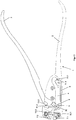
- FIG. 1 shows a typical embodiment of an inventive pliers 1 with closed mouth.
- An inventive pliers comprises in addition to a handle part 2 with a jaw part 7.1 a pressure lever 3. This pressure lever 3 is pivotally mounted relative to the handle part 2.
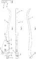
- FIG. 2 is the pliers 1 after FIG. 1 shown without a housing cover 8. There, a pivot point 13.2 is shown, about which the pressure lever 3 rotates or pivots in a typical embodiment.
- This rotation / pivot point is located on the jaw parts 7.1 and 7.2 facing side of the pressure lever.
- a pliers according to the invention comprises a lever arm 4 with a second jaw part 7.2. This is arranged in a typical embodiment between the handle part 2 and the pressure lever 3 and can be acted upon by the pressure lever 3 with pressure.
- This lever arm 4 is in FIG. 2 shown in a state used in the forceps 1. Furthermore, it is shown that the lever arm 4 has a pivot point 13.1 relative to the handle part 2, about which the lever arm is pivotally mounted relative to the handle part 2. This rotation / pivot point 13.1 is located on the side facing away from the jaw part 7.2 of the lever arm 4, to allow the highest possible translation and also a possible parallel arrangement.
- FIG. 2 and the FIG. 3 which shows the inventive pliers 1 without housing cover 8 in the open state, be taken that it is a free storage both during storage between the pressure lever 3 and the handle part 2 and during storage between the lever arm 4 and the handle part 2 , This allows easy disassembly of the forceps 1 by a user.
- the rolling element is guided in a gate 9.
- the gate 9 is for this purpose introduced into the handle part 2 and / or the housing cover 8.
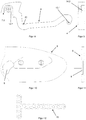
- the handle part 2 and the position of the backdrop in the handle part 2 are in the FIGS. 4 and 6 shown in more detail.
- the housing cover 8 and the position of the gate 9 in the housing cover are in the FIGS. 10 and 11 shown in more detail.
- the concave seat 20 for the rolling element in a typical embodiment has an inner radius which is greater than the outer radius of the rolling element 5 in the area of the rolling surface.
- the grip part 2 at least partially has a housing which serves to accommodate various individual parts of the forceps 1.
- the grip part 2 has a concave mount 11.2 on the side of the housing facing the jaw part 7.1.
- the concave seat 11.2 is adapted to receive the mouth-side end of the pressure lever 3 with the pivot point 13.2.
- the concave receptacle 11.2 has an inner radius which is greater than the outer radius of the pressure lever 3 about the pivot point 13.2.
- the handle 2 On the side facing away from the jaw 7.1 side of the housing, the handle 2 has a further concave seat 11.1.
- the receptacle 11.1 is adapted to receive the jaw part 7.2 opposite end of the lever arm 4, which has the rotation / pivot point 13.1.
- the concave receptacles 11.1 have an inner radius which is greater than the outer radius of the lever arm 4 about the pivot point 13.1.
- the grip part 2 has a recess on the side of the housing facing the jaw part 7.1, which recess is suitable for receiving the lever arm 4.
- the recess for receiving the lever arm 3 is formed in a typical embodiment in the form of a closed channel 10 in the direction of a longitudinal axis L of the handle part 2.
- the handle part 2 a EinschausANSung 12 for a spring 6, which is adapted to bring the pliers 1 from a use position with the mouth closed in a position of use with the mouth open.
- a firm connection of the handle part with the housing cover can be done via screws and / or a plug connection.
- the connection via not shown in the figures screws.
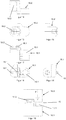
- the jaws 7.1 and 7.2 of the forceps 1 are aligned in an inventive embodiment of the forceps in the open state quasi-parallel to each other. Furthermore, the jaw parts 7.1 and 7.2 are adapted to receive tool elements 16.1 and 16.2. In a typical embodiment, the tool elements 16.1 and 16.2 are interchangeable.
- the tool elements 16. 1 and 16. 2 are preferably inserts which are suitable for cutting surgical implants 15. In FIG. 12 an embodiment of such an implant 15 is shown.
- the arrangement of the rotation / pivot points 13.1 and 13.2 a sufficiently high gear ratio is achieved to cut even high-strength titanium implants.
- the tool elements 16.1 and 16.2 are fixed by screwing in the receptacles 14.1 and 14.2, which are arranged in the jaw parts 7.1 and 7.2 of the handle part 2 and the lever arm 4.
- the cutting edges of the tool elements 16.1 and 16.2 are adapted to each other and to the surgical implant 15 in a typical embodiment.
- the tool elements 16.1 and 16.2 also recesses, which serve as a receptacle 19.1 and 19.2 for Federandschreiber 17.1 and 17.2.
- the spring presser 17.1 and 17.2 bending of the implant 15 is prevented during cutting. This is shown in FIG. 19 showing the cutting scheme for a typical embodiment.
- the spring-loaded 17.1 and 17.2 are preferably made of a solid, but elastic and thus deformable silicone.
- the spring contacts 17.1 and 17.2 are fixed in a typical embodiment by the screw in the tool elements 16.1 and 16.2, which fix the tool elements 16.1 and 16.2 in the receptacles 14.1 and 14.2 of the jaw parts 7.1 and 7.2.
Landscapes
- Engineering & Computer Science (AREA)
- Life Sciences & Earth Sciences (AREA)
- Health & Medical Sciences (AREA)
- Mechanical Engineering (AREA)
- Forests & Forestry (AREA)
- Surgery (AREA)
- Orthopedic Medicine & Surgery (AREA)
- Biomedical Technology (AREA)
- Nuclear Medicine, Radiotherapy & Molecular Imaging (AREA)
- Heart & Thoracic Surgery (AREA)
- Medical Informatics (AREA)
- Molecular Biology (AREA)
- Animal Behavior & Ethology (AREA)
- General Health & Medical Sciences (AREA)
- Public Health (AREA)
- Veterinary Medicine (AREA)
- Surgical Instruments (AREA)
Description
Die Erfindung betrifft eine Zange, insbesondere eine chirurgische Zange, nach dem Oberbegriff des Anspruchs 1.The invention relates to a forceps, in particular a surgical forceps, according to the preamble of
Aus dem Stand der Technik sind verschiedene chirurgische Zangen zum Schneiden von Implantaten und/oder medizinischen Drähten bekannt. Da zum Schneiden von Implantaten und/oder medizinischen Drähten oft hohe Scherkräfte erzeugt werden müssen, weisen diese Zangen meist mehrfache Übersetzungen, z.B. in Form von Kniehebelantrieben, auf. Weiterhin sind diese meist ergonomisch geformt, um vom Operateur mit einer Hand bedienbar zu sein.Various surgical forceps for cutting implants and / or medical wires are known in the art. Since for cutting implants and / or medical wires often high shear forces must be generated, these pliers usually have multiple translations, eg in the form of toggle drives on. Furthermore, these are usually ergonomically shaped to be operated by the surgeon with one hand.
In der
Eine weitere solche Zange mit mehreren Gelenken, die Kniehebelantriebe bilden, ist in der
Allgemein gilt im Bereich chirurgischer Instrumente, dass in jüngster Zeit die Reinigung von den komplexen Vorrichtungen ein wachsendes Problem darstellt. Während die Vorrichtungen technisch immer ausgefeilter werden, bedarf es zu ihrer Reinigung eines immer grösseren Aufwands. Dies gilt auch für die zuvor dargestellten Zangen aus der
Insbesondere stellen hier die Teilbereiche der Zangen, welche mittels eines Reinigungsprozesses, insbesondere unter Verwendung von Reinigungsmittel, nicht oder nur bedingt in einen sterilen Zustand versetzt werden können, ein immenses Risiko dar.In particular, the subregions of the forceps, which can not or only to a limited extent be placed in a sterile condition by means of a cleaning process, in particular using cleaning agents, represent an immense risk here.
Aus der
Aus der
Eine Zange der o.g. Art ist aus der
A pliers of the above kind is from the
Eine chirurgische Zange der im Oberbegriff von Anspruch 1 genannten Art ist aus der
Die Aufgabe der vorliegenden Erfindung ist es, die Nachteile des Standes der Technik zu überwinden. Insbesondere soll eine Zange bereitgestellt werden, die eine einfach erreichte, aber hohe Übersetzung ermöglicht. Weiterhin soll eine Zange bereitgestellt werden, bei der die Übersetzung ohne feste Verbindungen ausgebildet sein soll und die für verschiedene Zwecke genutzt werden kann.
Zudem sollen in Maulteilen eingebrachte Werkzeugelemente im geöffneten Zustand zumindest quasi-parallel zueinander ausgerichtet sein. Auch soll eine Zange bereitgestellt werden, bei der ohne großen Aufwand die Werkzeugelemente ausgetauscht werden können.The object of the present invention is to overcome the disadvantages of the prior art. In particular, a pair of pliers should be provided which allows a simple but high translation. Furthermore, a pair of pliers should be provided, in which the translation should be designed without fixed connections and which can be used for different purposes.
In addition, tool elements introduced into jaws should, in the opened state, be oriented at least quasi-parallel to one another. Also should a Pliers are provided in which the tool elements can be exchanged without much effort.
Zudem soll eine Zange bereitgestellt werden, die ohne grossen Aufwand bei einem Reinigungsprozess derart gereinigt werden kann, dass sie steril ist und weiterhin einfach in Einzelteile zerlegbar und ebenso einfach zusammensetzbar ist.In addition, a pair of pliers should be provided, which can be cleaned without great effort in a cleaning process so that it is sterile and still easy to disassemble into individual parts and just as easy to assemble.
Zur Lösung der Aufgabe führen die Merkmale nach dem Anspruch 1.To achieve the object, the features according to
Zum Erreichen einer hohen Übersetzung trägt bei, dass zwischen dem Druckhebel und dem Hebelarm der Wälzkörper angeordnet ist, Dieser Wälzkörper ist dabei so ausgeführt, dass er es ermöglicht, eine Kraft vom Druckhebel auf den Hebelarm zu übertragen. Um dies zu erreichen, wird der Wälzkörper in einer Kulisse geführt. Zusätzlich weist der Hebelarm eine vorzugsweise konkave Aufnahme für den Wälzkörper auf. Dadurch entsteht eine Art Kniehebel, der zur hohen Übersetzung der Zange beiträgt. Der Wälzkörper und der dadurch entstehende Kniehebel sind in einem typischen Ausführungsbeispiel in der dem Maulteil zugewandten Seite des Gehäuses des Griffteils angeordnet.To achieve a high translation contributes that is arranged between the pressure lever and the lever arm of the rolling elements, this rolling element is designed so that it makes it possible to transmit a force from the pressure lever to the lever arm. To achieve this, the rolling element is guided in a backdrop. In addition, the lever arm has a preferably concave receptacle for the rolling body. This creates a kind of toggle that contributes to the high translation of the pliers. The rolling elements and the resulting toggle lever are arranged in a typical embodiment in the jaw part facing the housing of the handle part.
Bei der Lagerung zwischen Griffteil und Druckhebel und der Lagerung zwischen Hebelarm und Griffteil handelt es sich um eine freie Lagerung. Diese Lagerungen befinden sich in einem Bereich des Griffteils, der als Teil eines Gehäuses ausgebildet ist. In einem typischen Ausführungsbeispiel sind die freien Lagerungen gelenkartig in Form eines Drehgelenks oder Drehschubgelenks ausgebildet.When storing between handle and pressure lever and the storage between the lever arm and handle part is a free storage. These bearings are located in a region of the grip part which is formed as part of a housing. In a typical embodiment, the free bearings are articulated in the form of a rotary joint or rotary joint.
Bei beiden freien Lagerungen handelt es sich um Wälzflächen, die ein Schwenken des Druckhebels und des Hebelarms zulassen. Vorzugsweise drehen der Hebelarm und/oder der Druckhebel dabei um einen Dreh-/Schwenkpunkt. Weiterhin besteht auch die Möglichkeit, das der Dreh-/Schwenkpunkt einen nicht punktuellen Bereich darstellt, in dem der Hebelarm und/oder der Druckhebel bei einer Betätigung der Zange innerhalb des Gehäuses schwenken können.Both free bearings are Wälzflächen that allow pivoting of the pressure lever and the lever arm. Preferably The lever arm and / or the pressure lever rotate about a pivot point. Furthermore, there is also the possibility that the rotation / pivot point represents a non-point area, in which the lever arm and / or the pressure lever can pivot within an actuation of the pliers within the housing.
Um eine möglichst hohe Übersetzung zu erreichen, vorzugsweise mindestens eine Übersetzung von 1 zu 15, befinden sich die Dreh-/Schwenkpunkte von dem Druckhebel und dem Hebelarm in möglichst grossem Abstand zueinander.In order to achieve the highest possible ratio, preferably at least one ratio of 1 to 15, the pivot points of the pressure lever and the lever arm are at the greatest possible distance from each other.
Der Dreh-/Schwenkpunkt des Druckhebels befindet sich dabei auf einer dem Maulteil zugewandten Seite des Druckhebels. Dieses Ende des Druckhebels wird in einem typischen Ausführungsbeispiel in eine konkave Aufnahme, die sich auf der dem Maulteil zugewandten Seite des Gehäuses im Griffteil befindet, eingesetzt. Die konkave Aufnahme stellt weiterhin die Wälzfläche dar, die als Lager des Druckhebels, anstelle eines konventionellen Gelenks in Form eines Bolzen oder Niets, dient.The rotation / pivot point of the pressure lever is located on a side facing the jaw part of the pressure lever. This end of the pressure lever is used in a typical embodiment in a concave receiving, which is located on the jaw side facing the housing in the handle part. The concave seat also represents the rolling surface, which serves as a bearing of the pressure lever, instead of a conventional joint in the form of a bolt or rivet.
Der Dreh-/Schwenkpunkt des Hebelarms befindet sich auf einer dem Maulteil abgewandten Seite des Hebelarms. Das dem Maulteil abgewandte Ende des Hebelarms wird in einem typischen Ausführungsbeispiel in eine konkave Aufnahme, die sich auf der dem Maulteil abgewandten Seite des Gehäuses im Griffteil befindet, eingesetzt. Die konkave Aufnahme stellt auch hier die Wälzfläche dar, die als Lager des Hebelarms, anstelle eines konventionellen Gelenks in Form eines Bolzen oder Niets, dient.The pivot point of the lever arm is located on a side facing away from the jaw part of the lever arm. The jaw part facing away from the end of the lever arm is used in a typical embodiment in a concave receiving, which is located on the side facing away from the jaw part of the housing in the handle part. The concave receptacle is also here the rolling surface, which serves as a bearing of the lever arm, instead of a conventional joint in the form of a bolt or rivet.
Durch die grösstmögliche Entfernung der Lagerung und somit des Dreh-/Schwenkpunktes des Hebelarms vom Maulteil wird neben der hohen Übersetzung erreicht, dass die Maulteile auch im geöffneten Zustand quasi-parallel zueinander ausgerichtet sind.By the greatest possible distance of the bearing and thus the rotation / pivot point of the lever arm of the jaw part is achieved in addition to the high translation, that the jaw parts are aligned quasi-parallel to each other in the open state.
Die Lagerungen zwischen Griffstück und Druckhebel, Griffstück und Hebelarm Druckhebel und Wälzkörper sowie Wälzkörper und Hebelarm weisen ähnliche bzw. dieselben Funktionen auf, die Gelenke in einer konventionellen Zange aufweisen. Daher handelt es sich in einem typischen Ausführungsbeispiel bei den konkaven Aufnahmen um eine Art Gelenkpfanne während es sich bei den Enden des Hebelarms und des Druckhebels um eine Art Gelenkkopf handelt. Ebenso handelt es sich in einem typischen Ausführungsbeispiel bei der dem Hebelarm zugewandten Seite des Wälzkörpers um eine Art Gelenkkopf.The bearings between handle and pressure lever, handle and lever arm Thrust levers and rolling elements as well as rolling elements and lever arm have similar or the same functions that have joints in a conventional pliers. Therefore, in a typical embodiment, the concave seats are a type of socket while the ends of the lever arm and the pressure lever are a type of condyle. Likewise, in a typical embodiment, the side of the rolling element facing the lever arm is a type of condyle.
Die Lagerung und somit der Dreh-/Schwenkpunkt zwischen dem Druckhebel und dem Griffstück sowie die Wälzflächen zwischen dem Wälzkörper und dem Druckhebel und zwischen dem Wälzkörper und dem Hebelarm befinden sich in einem typischen Ausführungsbeispiel auf der dem Maulteil zugewandten Seite des Gehäuses der Zange. Somit befindet sich in einem typischen Ausführungsbeispiel lediglich die Lagerung und somit der Dreh-/Schwenkpunkt zwischen Hebelarm und Griffstück auf der dem Maulteil abgewandten Seite des Gehäuses der Zange und somit weiter vom Maulteil entfernt.The bearing and thus the rotation / pivot point between the pressure lever and the handle and the rolling surfaces between the rolling element and the pressure lever and between the rolling element and the lever arm are in a typical embodiment of the jaw part facing the side of the housing of the forceps. Thus, in a typical embodiment, only the bearing and thus the pivot point between the lever arm and handle on the side facing away from the jaw part of the housing of the forceps and thus further away from the jaw part.
Durch die Nutzung von Wälzflächen zur Lagerung und des Wälzkörpers zur Ausgestaltung eines Kniehebels kann die Reibung innerhalb der Zange auf ein geringes Mass reduziert werden. Dadurch kann eine an den Maulteilen wirkende, grosse Kraft erzeugt werden. Da zur Erzeugung der Kraft nur ein geringer Weg benötigt wird, kann die Zange mit einer Hand genutzt und bedient werden.By using Wälzflächen for storage and the rolling element for the design of a toggle lever friction within the pliers can be reduced to a low level. As a result, a large force acting on the jaw parts can be generated. Since only a small way is needed to generate the force, the pliers can be used and operated with one hand.
Weiterhin weisen in einem typischen Ausführungsbeispiel die Bauteile im Bereich der Lagerungen bzw. der Wälzflächen meist ungleiche Geometrien, insbesondere ungleiche Radien auf. Beispielsweise kann eine Dreh- und/oder Drehschubbewegung dadurch erreicht werden, dass der Radius der jeweiligen konkaven Aufnahmen in einem typischen Ausführungsbeispiel grösser ist als der Aussenradius des Endes des jeweiligen Bauteils, welches in der Aufnahme gelagert ist. Dadurch wird eine abwälzende Bewegung und somit eine geringe Reibung ermöglicht.Furthermore, in a typical embodiment, the components in the region of the bearings or the rolling surfaces usually have unequal geometries, in particular unequal radii. For example, a rotary and / or rotary thrust movement can be achieved in that the radius of the respective concave seats in a typical embodiment is greater than the outer radius of the end of the respective component, which is mounted in the receptacle. This allows a rolling movement and thus a low friction.
Die Kulisse zur Führung des Wälzkörpers ist im Griffteil und/oder einem Gehäusedeckel eingebracht. Der Gehäusedeckel ist zum Verschliessen des zumindest teilweise vom Griffteil dargestellten Gehäuses geeignet. Die Verbindung des Gehäusedeckels mit dem Griffteil erfolgt vorzugsweise durch Schrauben. Möglich ist aber auch das Nutzen einer Steckverbindung anstelle der Verschraubung.The scenery for guiding the rolling element is introduced in the handle part and / or a housing cover. The housing cover is suitable for closing the housing, which is at least partially represented by the handle part. The connection of the housing cover with the handle part is preferably carried out by screws. But it is also possible to use a plug connection instead of screwing.
Weiterhin weist das Griffteil innerhalb des Gehäusebereichs eine Einhängeausnehmung auf, die dazu geeignet ist, eine Feder aufzunehmen. Durch die Feder wird das Maul der Zange wieder geöffnet, sobald der Druckhebel nicht mehr in Richtung des Griffteils gedrückt wird.Furthermore, the handle part within the housing portion on a Einhängeausnehmung, which is adapted to receive a spring. By the spring, the jaw of the pliers is opened again as soon as the pressure lever is no longer pressed in the direction of the handle part.
Weiterhin weist das Griffteil am maulseitigen Ende eine Ausnehmung auf, die als ein geschlossener Kanal in Richtung einer Längsachse ausgebildet ist. Die Längsachse entspricht dabei etwa einer gedachten Verbindung zwischen dem maulseitigen Ende und dem maulabgewandten Ende des Griffteils. Die als geschlossener Kanal ausgebildete Ausnehmung ist in einem typischen Ausführungsbeispiel dazu geeignet, den Hebelarm aufzunehmen, der hierfür vom maulseitigen Ende des Griffstücks aus in den geschlossenen Kanal eingeschoben wird.Furthermore, the handle part at the mouth-side end has a recess which is formed as a closed channel in the direction of a longitudinal axis. The Longitudinal axis corresponds approximately to an imaginary connection between the mouth-side end and the maulabgewandten end of the handle part. The recess formed as a closed channel is suitable in a typical embodiment to receive the lever arm, which is inserted for this purpose from the mouth-side end of the handle into the closed channel.
Durch die Ausbildung der Ausnehmung als geschlossener Kanal wird weiterhin erreicht, dass Griffteil und somit das Gehäuse in diesem Bereich eine höhere Stabilität aufweisen. Zudem können über die geschlossene Kontur der Ausnehmung einwirkende Kräfte besser in das Griffteil abgeleitet werden.By forming the recess as a closed channel is further achieved that handle part and thus the housing in this area have a higher stability. In addition, forces acting on the closed contour of the recess can be better dissipated into the grip part.
In einem typischen Ausführungsbeispiel sind die Maulteile der Zange zur Aufnahme von Werkzeugelementen geeignet. Diese werden vorzugsweise in dafür vorgesehenen Aufnahmen mit dem Maulteil verschraubt und somit im Griffteil und Hebelarm fixiert. Durch die Verschraubung ist es möglich, abgenutzte Werkzeugelemente auszuwechseln. Weiterhin besteht die Möglichkeit verschiedene Werkzeugelemente mit derselben Zange zu nutzen.In a typical embodiment, the jaw parts of the forceps are suitable for receiving tool elements. These are preferably screwed into provided receptacles with the jaw part and thus fixed in the handle part and lever arm. By screwing it is possible to replace worn tool elements. Furthermore, it is possible to use different tool elements with the same pliers.
Vorzugsweise kommen Werkzeugelemente zum Schneiden von chirurgischen Implantaten, insbesondere Titan-Implantaten, zum Einsatz. Weiterhin sind auch Werkzeugelemente denkbar und vorliegend umfasst, die zum Schneiden von Draht oder zum Biegen, Prägen, Stanzen und/oder Zwicken von verschiedensten Werkstücken und/oder Implantaten, auch ausserhalb des medizinischen Bereichs, geeignet sind.Preferably, tool elements are used for cutting surgical implants, in particular titanium implants. Furthermore, also tool elements are conceivable and presently included, which are suitable for cutting wire or for bending, stamping, punching and / or pinching of various workpieces and / or implants, also outside the medical field.
Die Werkzeugelemente zum Schneiden von chirurgischen Implantaten sind in Verbindung mit der hohen Übersetzung der Zange dazu geeignet auch Titan-Implantate mit grossen Stärken zu schneiden. Um dies zu erleichtern, weist zumindest eines der Werkzeugelemente zum Schneiden von chirurgischen Implantaten in einem typischen Ausführungsbeispiel Aufnahmestifte auf. Vorzugsweise ist die Form, Größe und/oder der Abstand der Aufnahmestifte auf die zu schneidenden chirurgischen Implantate angepasst. Durch die Aufnahmestifte kann das Implantat in der richtigen Position zwischen den Werkzeugelementen fixiert werden.The tool elements for cutting surgical implants in conjunction with the high ratio of the forceps are also suitable for cutting titanium implants with large thicknesses. To facilitate this, at least one of the tool elements for cutting surgical implants in a typical embodiment has receiving pins. Preferably, the shape, size and / or the distance of the recording pins adapted to the surgical implants to be cut. By the receiving pins, the implant can be fixed in the correct position between the tool elements.
Um ein Verbiegen des Implantats an der vorgesehenen Schnittkante beim Schneiden zu verhindern, weisen die Werkzeugelemente in einem Ausführungsbeispiel Federandrücker auf. Diese bestehen vorzugsweise aus einem festen, aber trotzdem elastischen und verformbaren medizinischen Silikon und drücken das zu schneidende Implantat an das gegenüberliegende Werkzeugelement.In order to prevent bending of the implant at the intended cutting edge during cutting, the tool elements have in one embodiment spring-loaded. These are preferably made of a solid, but still elastic and deformable medical silicone and press the implant to be cut on the opposite tool element.
Durch die typische Ausführungsform der Werkzeugelemente zum Schneiden von chirurgischen Implantaten mit den Aufnahmestiften und den Federandrückern und die quasi-parallele Anordnung der Werkzeugelemente kann zudem eine sehr saubere Führung des Schneidguts gewährleistet werden. Weiterhin wird durch die quasi-parallele Ausrichtung der Werkzeugelemente im geöffneten Zustand gewährleistet, dass ein Schneidgut beim Schliessen der Zange nicht aus den Schneiden heraus gleitet.By the typical embodiment of the tool elements for cutting surgical implants with the receiving pins and the Federandrückern and the quasi-parallel arrangement of the tool elements also a very clean guidance of the cutting material can be ensured. Furthermore, it is ensured by the quasi-parallel alignment of the tool elements in the open state that a material to be cut does not slide out of the cutting edges when closing the pliers.
In einem typischen Ausführungsbeispiel werden die Federandrücker in den Werkzeugelementen durch die Schrauben fixiert, die die Werkzeugelemente in den Maulteilen des Griffteils und des Hebelarms fixieren. Somit können auch die Federandrücker problemlos gewechselt werden.In a typical embodiment, the spring depressors in the tool elements are fixed by the screws which fix the tool elements in the jaw parts of the handle part and the lever arm. Thus, the spring contactors can be changed easily.
Durch die Ausführungsform der Lager, als eine Art Wälzlager, liegen der Druckhebel und der Hebelarm im geöffneten Zustand der Zange nicht in den Lagerflächen an. Auch die Feder liegt im geöffneten Zustand locker im Gehäuse. Somit steht im geöffneten Zustand keines der einzelnen Bauteile der Zange unter Spannung. Da somit im weit geöffneten Zustand keine angepressten Flächen wie in einem konventionellen Gelenk vorhanden sind, kann die Zange dadurch ohne ein vorheriges Zerlegen steril gereinigt werden Da sämtliche Verbindungen der Zange lösbar oder gesteckt ausgestaltet sind, können die Einzelteile der Zange ohne weiteres auch einzeln gereinigt werden. Auch ein Austauschen einzelner Teile ist problemlos möglich. Dies hat den Vorteil, dass bei einem Defekt eines Einzelteils, wie etwa der Feder, im Gehäuse oder eines Federandrückers in den Werkzeugelementen, nicht die gesamte Zange neu beschafft werden muss. Weiterhin kann durch den einfachen Aufbau der Zange diese ohne weiteres vom medizinischen Personal zerlegt und wieder zusammengesetzt werden.Due to the embodiment of the bearing, as a kind of rolling bearing, the pressure lever and the lever arm are not in the open state of the pliers in the bearing surfaces. The spring is loose in the housing in the open state. Thus, in the open state, none of the individual components of the pliers is under tension. Since thus in the wide open state no pressed surfaces are present as in a conventional joint, the forceps can thereby be cleaned sterile without a prior disassembly Since all connections of the pliers are designed detachable or plugged, the individual parts of the pliers can easily be cleaned individually. Even replacing individual parts is possible without any problems. This has the advantage that in case of a defect of an item, such as the spring, in the housing or a Federandrückers in the tool elements, not the entire pliers must be procured new. Furthermore, it can be easily disassembled by the medical staff and reassembled by the simple design of the forceps.
Weitere Vorteile, Merkmale und Einzelheiten der Erfindung ergeben sich aus der nachfolgenden Beschreibung bevorzugter Ausführungsbeispiele sowie anhand der Zeichnungen; diese zeigen in
Figur 1- eine typische Ausführungsform einer erfindungsgemässen Zange mit geschlossenem Maul;
Figur 2- das
Ausführungsbeispiel nach Figur 1 ohne Gehäusedeckel mit geschlossenem Maul; Figur 3- das
Ausführungsbeispiel nach Figur 2 mit geöffnetem Maul; Figur 4- eine Seitenansicht eines erfindungsgemässen Griffteils der Zange nach
Figur 1 ; Figur 5- eine Ansicht von der proximalen Seite des Griffteils nach
Figur 4 ; Figur 6- eine Draufsicht auf das
Griffteil nach Figur 1 ; - Figur 7
- eine Seitenansicht eines erfindungsgemässen Druckhebels der Zange nach
Figur 1 ; Figur 8- eine Seitenansicht eines erfindungsgemässen Druckhebels der Zange nach
Figur 1 ; Figur 9- eine Ansicht von der proximalen Seite des Hebelarms nach
Figur 8 ; Figur 10- eine Seitenansicht eines erfindungsgemässen Gehäusedeckels der Zange nach
Figur 1 ; - Figur 11
- eine Ansicht von der proximalen Seite des Gehäusedeckels nach
Figur 10 ; Figur 12- ein typisches Ausführungsbeispiel eines chirurgischen Implantats;
- Figur 13
- eine Draufsicht auf ein Werkzeugelement für den Hebelarm einer erfindungsgemässen Zange;
- Figur 14
- eine Vorderansicht des Werkzeugelements nach
Figur 13 ; Figur 15- eine Seitenansicht des Werkzeugelements nach
Figur 13 ; - Figur 16
- eine Draufsicht auf ein Werkzeugelement für das Griffteil einer erfindungsgemässen Zange;
- Figur 17
- eine Vorderansicht des Werkzeugelements nach
Figur 16 ; Figur 18- eine Seitenansicht des Werkzeugelements nach
Figur 16 ; - Figur 19
- ein Schneidschema der Werkzeugelemente für ein Implantat.
- FIG. 1
- a typical embodiment of an inventive pliers with closed mouth;
- FIG. 2
- the embodiment according to
FIG. 1 without housing cover with closed mouth; - FIG. 3
- the embodiment according to
FIG. 2 with open mouth; - FIG. 4
- a side view of an inventive grip part of the pliers
FIG. 1 ; - FIG. 5
- a view from the proximal side of the handle after
FIG. 4 ; - FIG. 6
- a plan view of the handle after
FIG. 1 ; - FIG. 7
- a side view of a novel pressure lever of the pliers according to
FIG. 1 ; - FIG. 8
- a side view of a novel pressure lever of the pliers according to
FIG. 1 ; - FIG. 9
- a view from the proximal side of the lever arm after
FIG. 8 ; - FIG. 10
- a side view of an inventive cover of the pliers according to
FIG. 1 ; - FIG. 11
- a view from the proximal side of the housing cover after
FIG. 10 ; - FIG. 12
- a typical embodiment of a surgical implant;
- FIG. 13
- a plan view of a tool element for the lever arm of an inventive pliers;
- FIG. 14
- a front view of the tool element after
FIG. 13 ; - FIG. 15
- a side view of the tool element after
FIG. 13 ; - FIG. 16
- a plan view of a tool element for the grip part of an inventive pliers;
- FIG. 17
- a front view of the tool element after
FIG. 16 ; - FIG. 18
- a side view of the tool element after
FIG. 16 ; - FIG. 19
- a cutting scheme of the tool elements for an implant.
In
Dieser Dreh-/Schwenkpunkt befindet sich auf der den Maulteilen 7.1 und 7.2 zugewandten Seite des Druckhebels 3.This rotation / pivot point is located on the jaw parts 7.1 and 7.2 facing side of the pressure lever. 3
Weiterhin umfasst eine erfindungsgemässe Zange einen Hebelarm 4 mit einem zweiten Maulteil 7.2. Dieser ist in einem typischen Ausführungsbeispiel zwischen dem Griffteil 2 und dem Druckhebel 3 angeordnet und kann von dem Druckhebel 3 mit Druck beaufschlagt werden.Furthermore, a pliers according to the invention comprises a
Dieser Hebelarm 4 ist in
Weiterhin kann der
Weiterhin ist in den
Um diese Kraft über den Wälzkörper 5 möglichst verlustfrei vom Druckhebel 3 auf den Hebelarm 4 zu übertragen, wird der Wälzkörper in einer Kulisse 9 geführt. Die Kulisse 9 ist hierfür in das Griffteil 2 und/oder den Gehäusedeckel 8 eingebracht. Das Griffteil 2 und die Lage der Kulisse im Griffteil 2 sind in den
Aus den
Auf der dem Maulteil 7.1 abgewandten Seite des Gehäuses weist das Griffstück 2 eine weitere konkave Aufnahme 11.1 auf. Die Aufnahme 11.1 ist geeignet, das dem Maulteil 7.2 gegenüberliegende Ende des Hebelarms 4 aufzunehmen, welches den Dreh-/Schwenkpunkt 13.1 aufweist. Die konkave Aufnahmen 11.1 weist in einem typischen Ausführungsbeispiel einen Innenradius auf, der grösser als der Aussenradius des Hebelarms 4 um den Dreh-/Schwenkpunkt 13.1 ist.On the side facing away from the jaw 7.1 side of the housing, the
Weiterhin weist das Griffteil 2 auf der dem Maulteil 7.1 zugewandten Seite des Gehäuses eine Ausnehmung auf, die geeignet ist, den Hebelarm 4 aufzunehmen. Die Ausnehmung zur Aufnahme des Hebelarms 3 ist in einem typischen Ausführungsbeispiel in Form eines geschlossenen Kanals 10 in Richtung einer Längsachse L des Griffteils 2 ausgebildet. Somit wird beim Zusammensetzten der Zange 1 der Hebelarm 4 von der maulseitigen Seite aus in den geschlossenen Kanal 10 eingeführt.Furthermore, the
Weiterhin weist das Griffteil 2 eine Einhängeausnehmung 12 für eine Feder 6 auf, welche dazu geeignet ist, die Zange 1 aus einer Gebrauchslage mit geschlossenem Maul in eine Gebrauchslage mit geöffneten Maul zu bringen. Das Gehäuse der Zange 1, welches zumindest teilweise vom Griffteil 1 gebildet wird, wird, wie in
Die Maulteile 7.1 und 7.2 der Zange 1 sind in einer erfindungsgemässen Ausführungsform der Zange auch im geöffneten Zustand quasi-parallel zueinander ausgerichtet. Weiterhin sind die Maulteile 7.1 und 7.2 dazu geeignet, Werkzeugelemente 16.1 und 16.2 aufzunehmen. In einem typischen Ausführungsbeispiel sind die Werkzeugelemente 16.1 und 16.2 auswechselbar. Vorzugsweise handelt es sich bei den Werkzeugelementen 16.1 und 16.2 um Einsätze, die zum Schneiden von chirurgischen Implantaten 15 geeignet sind. In
In einer erfindungsgemässen Ausführungsform der Zange 1 sind die Werkzeugelemente 16.1 und 16.2 durch Verschraubungen in den Aufnahmen 14.1 und 14.2 fixiert, die in den Maulteilen 7.1 und 7.2 des Griffteils 2 und des Hebelarms 4 angeordnet sind. Um das chirurgische Implantat 15 sauber und effektiv zu durchtrennen, sind die Schneiden der Werkzeugelemente 16.1 und 16.2 in einem typischen Ausführungsbeispiel aufeinander und auf das chirurgische Implantat 15 angepasst.In an inventive embodiment of the
Weiterhin weist, wie in den
In einem typischen Ausführungsbeispiel weisen die Werkzeugelemente 16.1.und 16.2 zudem Ausnehmungen auf, die als Aufnahme 19.1 und 19.2 für Federandrücker 17.1 und 17.2 dienen. Durch die Federandrücker 17.1 und 17.2 wird ein Verbiegen des Implantats 15 beim Schneiden verhindert. Dargestellt ist dies in
Um ein vollständiges Schliessen des Mauls der Zange 1 zu ermöglichen, sind die Federandrücker 17.1 und 17.2 vorzugsweise aus einem festen, aber elastischen und somit verformbaren Silikon hergestellt. Die Federandrücker 17.1 und 17.2 werden in einem typischen Ausführungsbeispiel durch die Verschraubungen in den Werkzeugelementen 16.1 und 16.2 fixiert, die die Werkzeugelemente 16.1 und 16.2 in den Aufnahmen 14.1 und 14.2 der Maulteile 7.1 und 7.2 fixieren.In order to allow a complete closure of the jaw of the
Im Folgenden wird die Funktionsweise der Zange 1 mit Werkzeugelementen 16.1 und 16.2 zum Schneiden von chirurgischen Implantaten 15 dargestellt. Die Werkzeugelemente 16.1 und 16.2 zum Schneiden von chirurgischen Implantaten sind in den
Um ein Implantat 15 zu schneiden, wird dieses in das geöffnete Maul der Zange 1 eingelegt. Durch die Aufnahmestifte 18.1 und 18.2 wird eine möglichst ideale Positionierung des Implantats15 zwischen den Werkzeugelementen 16.1.und 16.2 imMaulteil der Zange 1 erreicht.
- To cut an
implant 15, this is inserted into the open mouth of theforceps 1. By the receiving pins 18.1 and 18.2 one is possible ideal positioning of theimplant 15 between the tool elements 16.1 and 16.2 in the jaw part of theforceps 1 achieved.
Durch das Ausüben einer Kraft auf den Druckhebel 3 schwenkt dieser um den Dreh-/Schwenkpunkt 13.2 und übt eine Kraft auf den Wälzkörper 5 aus. Dieser wird hierdurch in der Kulisse 9 in Richtung des Hebelarms 4 geführt. Dadurch beginnt der Hebelarm 4 um den Dreh-/Schwenkpunkt 13.1 zu schwenken. Dadurch bewegt sich das Maulteil 7.2 des Hebelarms 4 in Richtung des Maulteils 7.1 des Griffteils 2.By exerting a force on the
Durch die Federandrücker 17.1 und 17.2 und die Aufnahmestifte 18.1 und 18.2 wird das Implantat 15 zwischen den Werkzeugelementen 16.1 und 16.2 fixiert. Durch das Zusammendrücken wirkt nun eine Kraft F auf das Implantat 15 und dieses wird dadurch an der vorgesehenen Schnittkante durchtrennt.
Claims (15)
- Forceps (1), in particular surgical forceps, comprising at least one handle part (2) and a pressure lever (3) which is mounted pivotably in relation to the handle part, and comprising a jaw consisting of two jaw parts (7.1, 7.2), wherein one of the jaw parts (7.1) is provided on the handle part (2) and wherein a lever arm (4) which has the second jaw part (7.2) and is pressurizable by the pressure lever (3) is arranged between the handle part (2) and the pressure lever (3) and the lever arm (4) is mounted pivotably in relation to the handle part (2), wherein a rolling body (5) is arranged between the pressure lever (3) and the lever arm (4) and a force exerted on the pressure lever (3) is transmittable via the rolling body (5) to the lever arm (4),
characterized
in that the rolling body (5) is guided in a slotted guide (9), the slotted guide (9) for guiding the rolling body (5) is provided in the handle part (2) and/or in a housing cover (8) and the lever arm (4) has a concave receptacle (20) for the rolling body (5) with an internal radius which is larger than an external radius of the rolling body (5) in the region of the rolling surfaces, wherein, by exerting a force on the pressure lever (3), the latter pivots about a fulcrum/pivot point (13.2) and exerts a force on the rolling body (5) which is thereby guided in the slotted guide (9) in the direction of the lever arm (4), as a result of which the lever arm (4) begins to pivot about a fulcrum/pivot point (13.1) and the jaw part (7.2) of the lever arm (4) moves in the direction of the jaw part (7.1) of the handle part (2), and the mounting between handle part (2) and pressure lever (3) and between the handle part (2) and the lever arm (4) is a free mounting. - Forceps (1) claim 1, characterized in that a fulcrum/pivot point (13.1) of the lever arm (4) is located on the side facing away from the jaw part (7.2).
- Forceps (1) according to one of the preceding claims, characterized in that a fulcrum/pivot point (13.2) of the pressure lever (3) is located on the side of the pressure lever (3) which faces the jaw parts (7.1, 7.2).
- Forceps (1) according to one of the preceding claims, characterized in that the handle part (2) is at least partially a part of a housing.
- Forceps (1) according to one of the preceding claims, characterized in that the handle part (2) has, at a jaw-side end, a concave receptacle (11.2) for the pressure lever (3).
- Forceps (1) according to one of the preceding claims, characterized in that the handle part (2) has, at an end facing away from the jaw, a concave receptacle (11.1) for the lever arm (4).
- Forceps (1) according to one of the preceding claims, characterized in that the handle part (2) has, at the jaw-side end, a recess which is suitable for receiving the lever arm (4).
- Forceps (1) according to claim 7, characterized in that the recess for receiving the lever arm (4) is designed as a closed channel (10) in the direction of a longitudinal axis (L) of the handle part (2).
- Forceps (1) according to one of the preceding claims, characterized in that the handle part (2) has a hook-in recess (12) which is suitable for receiving a spring (6).
- Forceps (1) according to one of the preceding claims, characterized in that the housing cover (8) is suitable for closing the housing.
- Forceps (1) according to one of the preceding claims, characterized in that the jaw parts (7.1, 7.2) are aligned virtually parallel to each other.
- Forceps (1) according to one of the preceding claims, characterized in that the jaw parts (7.1, 7.2) are suitable for receiving tool elements (16.1, 16.2) which are exchangeable.
- Forceps (1) according to claim 12, characterized in that at least one of the tool elements (16.1, 16.2) for cutting implants has receiving pins (18.1, 18.2) for receiving and securing the implant (15).
- Forceps (1) according to claim 12 or 13, characterized in that the tool elements (16.1, 16.2) for cutting implants (15) have spring pressers (17.1, 17.2).
- Forceps (1) according to one of claims 12 to 14, characterized in that the spring pressers (17.1, 17.2) are secured in the tool elements (16.1, 16.2) for cutting implants (15) by means of the screws in the tool elements (16.1, 16.2), which screws secure the tool elements (16.1, 16.2) in the handle part (2) and/or lever arm (4).
Applications Claiming Priority (2)
| Application Number | Priority Date | Filing Date | Title |
|---|---|---|---|
| DE201310105751 DE102013105751A1 (en) | 2013-06-04 | 2013-06-04 | tongs |
| PCT/EP2014/061455 WO2014195295A1 (en) | 2013-06-04 | 2014-06-03 | Forceps |
Publications (2)
| Publication Number | Publication Date |
|---|---|
| EP3003176A1 EP3003176A1 (en) | 2016-04-13 |
| EP3003176B1 true EP3003176B1 (en) | 2018-02-07 |
Family
ID=51062776
Family Applications (1)
| Application Number | Title | Priority Date | Filing Date |
|---|---|---|---|
| EP14734747.0A Active EP3003176B1 (en) | 2013-06-04 | 2014-06-03 | Forceps |
Country Status (4)
| Country | Link |
|---|---|
| US (1) | US9751224B2 (en) |
| EP (1) | EP3003176B1 (en) |
| DE (1) | DE102013105751A1 (en) |
| WO (1) | WO2014195295A1 (en) |
Families Citing this family (1)
| Publication number | Priority date | Publication date | Assignee | Title |
|---|---|---|---|---|
| DE102016105637B3 (en) * | 2016-03-24 | 2017-06-22 | Karl Klappenecker GmbH & Co. KG | Instrument, in particular surgical instrument |
Family Cites Families (11)
| Publication number | Priority date | Publication date | Assignee | Title |
|---|---|---|---|---|
| US103152A (en) * | 1870-05-17 | Improved bolt-ctttting device | ||
| GB139528A (en) * | 1918-05-10 | 1920-03-11 | George Hutchinson | Improvements in cutting and shearing tools |
| GB1593401A (en) * | 1977-05-06 | 1981-07-15 | Nat Res Dev | Handgrip tools |
| DE3743605A1 (en) | 1987-12-22 | 1989-07-06 | Delma Elektro Med App | SURGICAL PLIERS |
| DE9105152U1 (en) * | 1991-04-26 | 1991-09-26 | Josef Heiss Medizintechnik GmbH, 7200 Tuttlingen | Pliers for cutting surgical nails, wires, etc. |
| DE20018390U1 (en) | 2000-10-27 | 2001-01-18 | Wenzler Medizintechnik GmbH, 78665 Frittlingen | Cutting pliers |
| DE20207785U1 (en) | 2002-05-17 | 2003-09-25 | GEOMED Medizin-Technik GmbH & Co., 78532 Tuttlingen | Surgical cutter, has cavities in opposing cutting edges forming locating cavity for object being cut |
| US8316549B2 (en) * | 2009-12-09 | 2012-11-27 | Midwest Tool And Cutlery Company | Compound leverage hand tool with interchangeable tool head |
| US8713805B2 (en) * | 2010-07-27 | 2014-05-06 | Milwaukee Electric Tool Corporation | Hand cutting tool |
| DE102011001013A1 (en) | 2011-03-02 | 2012-09-06 | Alexander Merz | Pliers for cutting workpieces |
| JP6227325B2 (en) * | 2013-08-27 | 2017-11-08 | 株式会社貝印刃物開発センター | scissors |
-
2013
- 2013-06-04 DE DE201310105751 patent/DE102013105751A1/en not_active Withdrawn
-
2014
- 2014-06-03 WO PCT/EP2014/061455 patent/WO2014195295A1/en not_active Ceased
- 2014-06-03 EP EP14734747.0A patent/EP3003176B1/en active Active
- 2014-06-03 US US14/895,574 patent/US9751224B2/en active Active
Also Published As
| Publication number | Publication date |
|---|---|
| EP3003176A1 (en) | 2016-04-13 |
| DE102013105751A1 (en) | 2014-12-04 |
| WO2014195295A1 (en) | 2014-12-11 |
| US9751224B2 (en) | 2017-09-05 |
| US20160257007A1 (en) | 2016-09-08 |
Similar Documents
| Publication | Publication Date | Title |
|---|---|---|
| DE3802651C2 (en) | Medical forceps, in particular arthroscopic forceps | |
| EP2612609B1 (en) | Medical instrument | |
| DE3709067A1 (en) | Medical, especially surgical, instrument | |
| EP1941975A2 (en) | Hydraulic pliers for grouting of workpieces | |
| EP1996091A2 (en) | Surgical instrument | |
| WO2009098589A1 (en) | Surgical instrument which can be disassembled | |
| EP0490066B1 (en) | Pliers for crimping wire end ferrules | |
| EP1488749B1 (en) | Medical instrument | |
| DE10028896B4 (en) | Medical instrument | |
| EP2272437A2 (en) | Surgical spreading instrument | |
| DE2755482C2 (en) | ||
| DE10136964A1 (en) | Surgical instrument | |
| DE10111766B4 (en) | Medical instrument | |
| DE4115937A1 (en) | Surgical cutting instrument - has frame to support guide for sliding blade which is actuated by pivoting handle | |
| EP2680773B1 (en) | Pliers for cutting workpieces | |
| EP1339332B1 (en) | Medical instrument | |
| DE19713067C2 (en) | Arthroscopy instrument | |
| EP3003176B1 (en) | Forceps | |
| DE3739254A1 (en) | Medical, in particular surgical, instrument | |
| DE102012022573A1 (en) | Medical instrument | |
| EP1629785A2 (en) | Medical forceps | |
| DE102016105637B3 (en) | Instrument, in particular surgical instrument | |
| EP3621535A1 (en) | Surgical instrument having improved closing characteristics | |
| DE10353552A1 (en) | Surgical instrument for removing tissue specimen of human body, has two handle parts with teeth, and pressure lever to lift one tooth from other tooth to actuate handle parts when pressure is exerted on lever | |
| EP2965701B1 (en) | Rod-type barrel clamp |
Legal Events
| Date | Code | Title | Description |
|---|---|---|---|
| PUAI | Public reference made under article 153(3) epc to a published international application that has entered the european phase |
Free format text: ORIGINAL CODE: 0009012 |
|
| 17P | Request for examination filed |
Effective date: 20151130 |
|
| AK | Designated contracting states |
Kind code of ref document: A1 Designated state(s): AL AT BE BG CH CY CZ DE DK EE ES FI FR GB GR HR HU IE IS IT LI LT LU LV MC MK MT NL NO PL PT RO RS SE SI SK SM TR |
|
| AX | Request for extension of the european patent |
Extension state: BA ME |
|
| DAX | Request for extension of the european patent (deleted) | ||
| GRAP | Despatch of communication of intention to grant a patent |
Free format text: ORIGINAL CODE: EPIDOSNIGR1 |
|
| INTG | Intention to grant announced |
Effective date: 20170421 |
|
| GRAS | Grant fee paid |
Free format text: ORIGINAL CODE: EPIDOSNIGR3 |
|
| GRAA | (expected) grant |
Free format text: ORIGINAL CODE: 0009210 |
|
| AK | Designated contracting states |
Kind code of ref document: B1 Designated state(s): AL AT BE BG CH CY CZ DE DK EE ES FI FR GB GR HR HU IE IS IT LI LT LU LV MC MK MT NL NO PL PT RO RS SE SI SK SM TR |
|
| REG | Reference to a national code |
Ref country code: GB Ref legal event code: FG4D Free format text: NOT ENGLISH |
|
| REG | Reference to a national code |
Ref country code: AT Ref legal event code: REF Ref document number: 968484 Country of ref document: AT Kind code of ref document: T Effective date: 20180215 Ref country code: CH Ref legal event code: EP |
|
| REG | Reference to a national code |
Ref country code: IE Ref legal event code: FG4D Free format text: LANGUAGE OF EP DOCUMENT: GERMAN |
|
| REG | Reference to a national code |
Ref country code: DE Ref legal event code: R096 Ref document number: 502014007204 Country of ref document: DE |
|
| REG | Reference to a national code |
Ref country code: NL Ref legal event code: MP Effective date: 20180207 |
|
| REG | Reference to a national code |
Ref country code: FR Ref legal event code: PLFP Year of fee payment: 5 |
|
| PG25 | Lapsed in a contracting state [announced via postgrant information from national office to epo] |
Ref country code: FI Free format text: LAPSE BECAUSE OF FAILURE TO SUBMIT A TRANSLATION OF THE DESCRIPTION OR TO PAY THE FEE WITHIN THE PRESCRIBED TIME-LIMIT Effective date: 20180207 Ref country code: NO Free format text: LAPSE BECAUSE OF FAILURE TO SUBMIT A TRANSLATION OF THE DESCRIPTION OR TO PAY THE FEE WITHIN THE PRESCRIBED TIME-LIMIT Effective date: 20180507 Ref country code: LT Free format text: LAPSE BECAUSE OF FAILURE TO SUBMIT A TRANSLATION OF THE DESCRIPTION OR TO PAY THE FEE WITHIN THE PRESCRIBED TIME-LIMIT Effective date: 20180207 Ref country code: HR Free format text: LAPSE BECAUSE OF FAILURE TO SUBMIT A TRANSLATION OF THE DESCRIPTION OR TO PAY THE FEE WITHIN THE PRESCRIBED TIME-LIMIT Effective date: 20180207 Ref country code: ES Free format text: LAPSE BECAUSE OF FAILURE TO SUBMIT A TRANSLATION OF THE DESCRIPTION OR TO PAY THE FEE WITHIN THE PRESCRIBED TIME-LIMIT Effective date: 20180207 Ref country code: NL Free format text: LAPSE BECAUSE OF FAILURE TO SUBMIT A TRANSLATION OF THE DESCRIPTION OR TO PAY THE FEE WITHIN THE PRESCRIBED TIME-LIMIT Effective date: 20180207 Ref country code: CY Free format text: LAPSE BECAUSE OF FAILURE TO SUBMIT A TRANSLATION OF THE DESCRIPTION OR TO PAY THE FEE WITHIN THE PRESCRIBED TIME-LIMIT Effective date: 20180207 |
|
| PG25 | Lapsed in a contracting state [announced via postgrant information from national office to epo] |
Ref country code: GR Free format text: LAPSE BECAUSE OF FAILURE TO SUBMIT A TRANSLATION OF THE DESCRIPTION OR TO PAY THE FEE WITHIN THE PRESCRIBED TIME-LIMIT Effective date: 20180508 Ref country code: IS Free format text: LAPSE BECAUSE OF FAILURE TO SUBMIT A TRANSLATION OF THE DESCRIPTION OR TO PAY THE FEE WITHIN THE PRESCRIBED TIME-LIMIT Effective date: 20180607 Ref country code: PL Free format text: LAPSE BECAUSE OF FAILURE TO SUBMIT A TRANSLATION OF THE DESCRIPTION OR TO PAY THE FEE WITHIN THE PRESCRIBED TIME-LIMIT Effective date: 20180207 Ref country code: LV Free format text: LAPSE BECAUSE OF FAILURE TO SUBMIT A TRANSLATION OF THE DESCRIPTION OR TO PAY THE FEE WITHIN THE PRESCRIBED TIME-LIMIT Effective date: 20180207 Ref country code: SE Free format text: LAPSE BECAUSE OF FAILURE TO SUBMIT A TRANSLATION OF THE DESCRIPTION OR TO PAY THE FEE WITHIN THE PRESCRIBED TIME-LIMIT Effective date: 20180207 Ref country code: RS Free format text: LAPSE BECAUSE OF FAILURE TO SUBMIT A TRANSLATION OF THE DESCRIPTION OR TO PAY THE FEE WITHIN THE PRESCRIBED TIME-LIMIT Effective date: 20180207 Ref country code: BG Free format text: LAPSE BECAUSE OF FAILURE TO SUBMIT A TRANSLATION OF THE DESCRIPTION OR TO PAY THE FEE WITHIN THE PRESCRIBED TIME-LIMIT Effective date: 20180507 |
|
| PG25 | Lapsed in a contracting state [announced via postgrant information from national office to epo] |
Ref country code: MT Free format text: LAPSE BECAUSE OF FAILURE TO SUBMIT A TRANSLATION OF THE DESCRIPTION OR TO PAY THE FEE WITHIN THE PRESCRIBED TIME-LIMIT Effective date: 20180207 |
|
| PG25 | Lapsed in a contracting state [announced via postgrant information from national office to epo] |
Ref country code: EE Free format text: LAPSE BECAUSE OF FAILURE TO SUBMIT A TRANSLATION OF THE DESCRIPTION OR TO PAY THE FEE WITHIN THE PRESCRIBED TIME-LIMIT Effective date: 20180207 Ref country code: AL Free format text: LAPSE BECAUSE OF FAILURE TO SUBMIT A TRANSLATION OF THE DESCRIPTION OR TO PAY THE FEE WITHIN THE PRESCRIBED TIME-LIMIT Effective date: 20180207 Ref country code: IT Free format text: LAPSE BECAUSE OF FAILURE TO SUBMIT A TRANSLATION OF THE DESCRIPTION OR TO PAY THE FEE WITHIN THE PRESCRIBED TIME-LIMIT Effective date: 20180207 Ref country code: RO Free format text: LAPSE BECAUSE OF FAILURE TO SUBMIT A TRANSLATION OF THE DESCRIPTION OR TO PAY THE FEE WITHIN THE PRESCRIBED TIME-LIMIT Effective date: 20180207 |
|
| REG | Reference to a national code |
Ref country code: DE Ref legal event code: R097 Ref document number: 502014007204 Country of ref document: DE |
|
| PG25 | Lapsed in a contracting state [announced via postgrant information from national office to epo] |
Ref country code: CZ Free format text: LAPSE BECAUSE OF FAILURE TO SUBMIT A TRANSLATION OF THE DESCRIPTION OR TO PAY THE FEE WITHIN THE PRESCRIBED TIME-LIMIT Effective date: 20180207 Ref country code: DK Free format text: LAPSE BECAUSE OF FAILURE TO SUBMIT A TRANSLATION OF THE DESCRIPTION OR TO PAY THE FEE WITHIN THE PRESCRIBED TIME-LIMIT Effective date: 20180207 Ref country code: SM Free format text: LAPSE BECAUSE OF FAILURE TO SUBMIT A TRANSLATION OF THE DESCRIPTION OR TO PAY THE FEE WITHIN THE PRESCRIBED TIME-LIMIT Effective date: 20180207 Ref country code: SK Free format text: LAPSE BECAUSE OF FAILURE TO SUBMIT A TRANSLATION OF THE DESCRIPTION OR TO PAY THE FEE WITHIN THE PRESCRIBED TIME-LIMIT Effective date: 20180207 |
|
| PLBE | No opposition filed within time limit |
Free format text: ORIGINAL CODE: 0009261 |
|
| STAA | Information on the status of an ep patent application or granted ep patent |
Free format text: STATUS: NO OPPOSITION FILED WITHIN TIME LIMIT |
|
| 26N | No opposition filed |
Effective date: 20181108 |
|
| GBPC | Gb: european patent ceased through non-payment of renewal fee |
Effective date: 20180603 |
|
| PG25 | Lapsed in a contracting state [announced via postgrant information from national office to epo] |
Ref country code: SI Free format text: LAPSE BECAUSE OF FAILURE TO SUBMIT A TRANSLATION OF THE DESCRIPTION OR TO PAY THE FEE WITHIN THE PRESCRIBED TIME-LIMIT Effective date: 20180207 |
|
| REG | Reference to a national code |
Ref country code: BE Ref legal event code: MM Effective date: 20180630 |
|
| REG | Reference to a national code |
Ref country code: IE Ref legal event code: MM4A |
|
| PG25 | Lapsed in a contracting state [announced via postgrant information from national office to epo] |
Ref country code: LU Free format text: LAPSE BECAUSE OF NON-PAYMENT OF DUE FEES Effective date: 20180603 Ref country code: MC Free format text: LAPSE BECAUSE OF FAILURE TO SUBMIT A TRANSLATION OF THE DESCRIPTION OR TO PAY THE FEE WITHIN THE PRESCRIBED TIME-LIMIT Effective date: 20180207 |
|
| PG25 | Lapsed in a contracting state [announced via postgrant information from national office to epo] |
Ref country code: GB Free format text: LAPSE BECAUSE OF NON-PAYMENT OF DUE FEES Effective date: 20180603 Ref country code: IE Free format text: LAPSE BECAUSE OF NON-PAYMENT OF DUE FEES Effective date: 20180603 |
|
| PG25 | Lapsed in a contracting state [announced via postgrant information from national office to epo] |
Ref country code: BE Free format text: LAPSE BECAUSE OF NON-PAYMENT OF DUE FEES Effective date: 20180630 |
|
| PG25 | Lapsed in a contracting state [announced via postgrant information from national office to epo] |
Ref country code: TR Free format text: LAPSE BECAUSE OF FAILURE TO SUBMIT A TRANSLATION OF THE DESCRIPTION OR TO PAY THE FEE WITHIN THE PRESCRIBED TIME-LIMIT Effective date: 20180207 |
|
| PG25 | Lapsed in a contracting state [announced via postgrant information from national office to epo] |
Ref country code: PT Free format text: LAPSE BECAUSE OF FAILURE TO SUBMIT A TRANSLATION OF THE DESCRIPTION OR TO PAY THE FEE WITHIN THE PRESCRIBED TIME-LIMIT Effective date: 20180207 |
|
| PG25 | Lapsed in a contracting state [announced via postgrant information from national office to epo] |
Ref country code: HU Free format text: LAPSE BECAUSE OF FAILURE TO SUBMIT A TRANSLATION OF THE DESCRIPTION OR TO PAY THE FEE WITHIN THE PRESCRIBED TIME-LIMIT; INVALID AB INITIO Effective date: 20140603 Ref country code: MK Free format text: LAPSE BECAUSE OF NON-PAYMENT OF DUE FEES Effective date: 20180207 |
|
| REG | Reference to a national code |
Ref country code: AT Ref legal event code: MM01 Ref document number: 968484 Country of ref document: AT Kind code of ref document: T Effective date: 20190603 |
|
| PG25 | Lapsed in a contracting state [announced via postgrant information from national office to epo] |
Ref country code: AT Free format text: LAPSE BECAUSE OF NON-PAYMENT OF DUE FEES Effective date: 20190603 |
|
| PGFP | Annual fee paid to national office [announced via postgrant information from national office to epo] |
Ref country code: FR Payment date: 20250623 Year of fee payment: 12 |
|
| PGFP | Annual fee paid to national office [announced via postgrant information from national office to epo] |
Ref country code: DE Payment date: 20250827 Year of fee payment: 12 |
|
| PGFP | Annual fee paid to national office [announced via postgrant information from national office to epo] |
Ref country code: CH Payment date: 20250701 Year of fee payment: 12 |