EP3003176B1 - Pince - Google Patents
Pince Download PDFInfo
- Publication number
- EP3003176B1 EP3003176B1 EP14734747.0A EP14734747A EP3003176B1 EP 3003176 B1 EP3003176 B1 EP 3003176B1 EP 14734747 A EP14734747 A EP 14734747A EP 3003176 B1 EP3003176 B1 EP 3003176B1
- Authority
- EP
- European Patent Office
- Prior art keywords
- forceps
- handle part
- lever arm
- jaw
- lever
- Prior art date
- Legal status (The legal status is an assumption and is not a legal conclusion. Google has not performed a legal analysis and makes no representation as to the accuracy of the status listed.)
- Active
Links
Images

Classifications
-
- B—PERFORMING OPERATIONS; TRANSPORTING
- B26—HAND CUTTING TOOLS; CUTTING; SEVERING
- B26B—HAND-HELD CUTTING TOOLS NOT OTHERWISE PROVIDED FOR
- B26B13/00—Hand shears; Scissors
- B26B13/04—Hand shears; Scissors with detachable blades
-
- A—HUMAN NECESSITIES
- A61—MEDICAL OR VETERINARY SCIENCE; HYGIENE
- A61B—DIAGNOSIS; SURGERY; IDENTIFICATION
- A61B17/00—Surgical instruments, devices or methods
- A61B17/56—Surgical instruments or methods for treatment of bones or joints; Devices specially adapted therefor
- A61B17/58—Surgical instruments or methods for treatment of bones or joints; Devices specially adapted therefor for osteosynthesis, e.g. bone plates, screws or setting implements
- A61B17/88—Osteosynthesis instruments; Methods or means for implanting or extracting internal or external fixation devices
- A61B17/8863—Apparatus for shaping or cutting osteosynthesis equipment by medical personnel
-
- B—PERFORMING OPERATIONS; TRANSPORTING
- B23—MACHINE TOOLS; METAL-WORKING NOT OTHERWISE PROVIDED FOR
- B23D—PLANING; SLOTTING; SHEARING; BROACHING; SAWING; FILING; SCRAPING; LIKE OPERATIONS FOR WORKING METAL BY REMOVING MATERIAL, NOT OTHERWISE PROVIDED FOR
- B23D29/00—Hand-held metal-shearing or metal-cutting devices
- B23D29/02—Hand-operated metal-shearing devices
- B23D29/023—Hand-operated metal-shearing devices for cutting wires
-
- B—PERFORMING OPERATIONS; TRANSPORTING
- B26—HAND CUTTING TOOLS; CUTTING; SEVERING
- B26B—HAND-HELD CUTTING TOOLS NOT OTHERWISE PROVIDED FOR
- B26B13/00—Hand shears; Scissors
- B26B13/28—Joints
-
- B—PERFORMING OPERATIONS; TRANSPORTING
- B26—HAND CUTTING TOOLS; CUTTING; SEVERING
- B26B—HAND-HELD CUTTING TOOLS NOT OTHERWISE PROVIDED FOR
- B26B29/00—Guards or sheaths or guides for hand cutting tools; Arrangements for guiding hand cutting tools
-
- A—HUMAN NECESSITIES
- A61—MEDICAL OR VETERINARY SCIENCE; HYGIENE
- A61B—DIAGNOSIS; SURGERY; IDENTIFICATION
- A61B17/00—Surgical instruments, devices or methods
- A61B2017/00526—Methods of manufacturing
Definitions
- the invention relates to a forceps, in particular a surgical forceps, according to the preamble of claim 1.
- the subregions of the forceps which can not or only to a limited extent be placed in a sterile condition by means of a cleaning process, in particular using cleaning agents, represent an immense risk here.
- a pair of pliers for cutting workpieces in particular of metal, with at least one pliers limb and a pressure element known which via a pivot point with each other are connected.
- the pliers leg is to be assigned a cutting element with a cutting jaw, wherein a base of the pliers mouth and a bottom of the cutting jaw are arranged near a pivot about which rotates the cutting element in the pliers legs.
- a ratchet wheel is rotatably mounted about a rotation axis on a Zargenschenkel, wherein the rotation is effected by the other pliers leg.
- the ratchet wheel has a sliding block, which runs with its surface a cutting element on which a jaw part is provided.
- a pliers of the above kind is from the GB 139 528 A known, wherein a handle part is associated with a pressure lever which is pivotally mounted relative to the handle part. On the handle part a jaw part is provided. Further, a lever arm is arranged between the handle part and the pressure lever, which has a second jaw part and can be acted upon by the pressure lever with pressure. The lever arm is pivotally mounted relative to the handle part.
- a surgical forceps referred to in the preamble of claim 1 is known from DE 200 18 390 U1 known.
- the object of the present invention is to overcome the disadvantages of the prior art.
- a pair of pliers should be provided which allows a simple but high translation.
- a pair of pliers should be provided, in which the translation should be designed without fixed connections and which can be used for different purposes.
- tool elements introduced into jaws should, in the opened state, be oriented at least quasi-parallel to one another.
- Pliers are provided in which the tool elements can be exchanged without much effort.
- a pair of pliers should be provided, which can be cleaned without great effort in a cleaning process so that it is sterile and still easy to disassemble into individual parts and just as easy to assemble.
- this rolling element is designed so that it makes it possible to transmit a force from the pressure lever to the lever arm.
- the rolling element is guided in a backdrop.
- the lever arm has a preferably concave receptacle for the rolling body. This creates a kind of toggle that contributes to the high translation of the pliers.
- the rolling elements and the resulting toggle lever are arranged in a typical embodiment in the jaw part facing the housing of the handle part.
- Both free bearings are Wälzvid that allow pivoting of the pressure lever and the lever arm.
- the lever arm and / or the pressure lever rotate about a pivot point.
- the rotation / pivot point represents a non-point area, in which the lever arm and / or the pressure lever can pivot within an actuation of the pliers within the housing.
- the pivot points of the pressure lever and the lever arm are at the greatest possible distance from each other.
- the rotation / pivot point of the pressure lever is located on a side facing the jaw part of the pressure lever.
- This end of the pressure lever is used in a typical embodiment in a concave receiving, which is located on the jaw side facing the housing in the handle part.
- the concave seat also represents the rolling surface, which serves as a bearing of the pressure lever, instead of a conventional joint in the form of a bolt or rivet.
- the pivot point of the lever arm is located on a side facing away from the jaw part of the lever arm.
- the jaw part facing away from the end of the lever arm is used in a typical embodiment in a concave receiving, which is located on the side facing away from the jaw part of the housing in the handle part.
- the concave receptacle is also here the rolling surface, which serves as a bearing of the lever arm, instead of a conventional joint in the form of a bolt or rivet.
- Thrust levers and rolling elements as well as rolling elements and lever arm have similar or the same functions that have joints in a conventional pliers. Therefore, in a typical embodiment, the concave seats are a type of socket while the ends of the lever arm and the pressure lever are a type of condyle. Likewise, in a typical embodiment, the side of the rolling element facing the lever arm is a type of condyle.
- the bearing and thus the rotation / pivot point between the pressure lever and the handle and the rolling surfaces between the rolling element and the pressure lever and between the rolling element and the lever arm are in a typical embodiment of the jaw part facing the side of the housing of the forceps.
- the components in the region of the bearings or the rolling surfaces usually have unequal geometries, in particular unequal radii.
- a rotary and / or rotary thrust movement can be achieved in that the radius of the respective concave seats in a typical embodiment is greater than the outer radius of the end of the respective component, which is mounted in the receptacle. This allows a rolling movement and thus a low friction.
- the scenery for guiding the rolling element is introduced in the handle part and / or a housing cover.
- the housing cover is suitable for closing the housing, which is at least partially represented by the handle part.
- the connection of the housing cover with the handle part is preferably carried out by screws. But it is also possible to use a plug connection instead of screwing.
- the handle part at the mouth-side end has a recess which is formed as a closed channel in the direction of a longitudinal axis.
- the Longitudinal axis corresponds approximately to an imaginary connection between the mouth-side end and the maulabgewandten end of the handle part.
- the recess formed as a closed channel is suitable in a typical embodiment to receive the lever arm, which is inserted for this purpose from the mouth-side end of the handle into the closed channel.
- the recess By forming the recess as a closed channel is further achieved that handle part and thus the housing in this area have a higher stability. In addition, forces acting on the closed contour of the recess can be better dissipated into the grip part.
- the jaw parts of the forceps are suitable for receiving tool elements. These are preferably screwed into provided receptacles with the jaw part and thus fixed in the handle part and lever arm. By screwing it is possible to replace worn tool elements. Furthermore, it is possible to use different tool elements with the same pliers.
- tool elements are used for cutting surgical implants, in particular titanium implants.
- tool elements are conceivable and presently included, which are suitable for cutting wire or for bending, stamping, punching and / or pinching of various workpieces and / or implants, also outside the medical field.
- the tool elements for cutting surgical implants in conjunction with the high ratio of the forceps are also suitable for cutting titanium implants with large thicknesses.
- at least one of the tool elements for cutting surgical implants in a typical embodiment has receiving pins.
- the implant can be fixed in the correct position between the tool elements.
- the tool elements In order to prevent bending of the implant at the intended cutting edge during cutting, the tool elements have in one embodiment spring-loaded. These are preferably made of a solid, but still elastic and deformable medical silicone and press the implant to be cut on the opposite tool element.
- the spring depressors in the tool elements are fixed by the screws which fix the tool elements in the jaw parts of the handle part and the lever arm.
- the spring contactors can be changed easily.
- the pressure lever and the lever arm are not in the open state of the pliers in the bearing surfaces.
- the spring is loose in the housing in the open state.
- none of the individual components of the pliers is under tension. Since thus in the wide open state no pressed surfaces are present as in a conventional joint, the forceps can thereby be cleaned sterile without a prior disassembly Since all connections of the pliers are designed detachable or plugged, the individual parts of the pliers can easily be cleaned individually. Even replacing individual parts is possible without any problems.
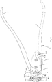
- FIG. 1 shows a typical embodiment of an inventive pliers 1 with closed mouth.
- An inventive pliers comprises in addition to a handle part 2 with a jaw part 7.1 a pressure lever 3. This pressure lever 3 is pivotally mounted relative to the handle part 2.
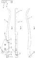
- FIG. 2 is the pliers 1 after FIG. 1 shown without a housing cover 8. There, a pivot point 13.2 is shown, about which the pressure lever 3 rotates or pivots in a typical embodiment.
- This rotation / pivot point is located on the jaw parts 7.1 and 7.2 facing side of the pressure lever.
- a pliers according to the invention comprises a lever arm 4 with a second jaw part 7.2. This is arranged in a typical embodiment between the handle part 2 and the pressure lever 3 and can be acted upon by the pressure lever 3 with pressure.
- This lever arm 4 is in FIG. 2 shown in a state used in the forceps 1. Furthermore, it is shown that the lever arm 4 has a pivot point 13.1 relative to the handle part 2, about which the lever arm is pivotally mounted relative to the handle part 2. This rotation / pivot point 13.1 is located on the side facing away from the jaw part 7.2 of the lever arm 4, to allow the highest possible translation and also a possible parallel arrangement.
- FIG. 2 and the FIG. 3 which shows the inventive pliers 1 without housing cover 8 in the open state, be taken that it is a free storage both during storage between the pressure lever 3 and the handle part 2 and during storage between the lever arm 4 and the handle part 2 , This allows easy disassembly of the forceps 1 by a user.
- the rolling element is guided in a gate 9.
- the gate 9 is for this purpose introduced into the handle part 2 and / or the housing cover 8.
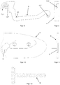
- the handle part 2 and the position of the backdrop in the handle part 2 are in the FIGS. 4 and 6 shown in more detail.
- the housing cover 8 and the position of the gate 9 in the housing cover are in the FIGS. 10 and 11 shown in more detail.
- the concave seat 20 for the rolling element in a typical embodiment has an inner radius which is greater than the outer radius of the rolling element 5 in the area of the rolling surface.
- the grip part 2 at least partially has a housing which serves to accommodate various individual parts of the forceps 1.
- the grip part 2 has a concave mount 11.2 on the side of the housing facing the jaw part 7.1.
- the concave seat 11.2 is adapted to receive the mouth-side end of the pressure lever 3 with the pivot point 13.2.
- the concave receptacle 11.2 has an inner radius which is greater than the outer radius of the pressure lever 3 about the pivot point 13.2.
- the handle 2 On the side facing away from the jaw 7.1 side of the housing, the handle 2 has a further concave seat 11.1.
- the receptacle 11.1 is adapted to receive the jaw part 7.2 opposite end of the lever arm 4, which has the rotation / pivot point 13.1.
- the concave receptacles 11.1 have an inner radius which is greater than the outer radius of the lever arm 4 about the pivot point 13.1.
- the grip part 2 has a recess on the side of the housing facing the jaw part 7.1, which recess is suitable for receiving the lever arm 4.
- the recess for receiving the lever arm 3 is formed in a typical embodiment in the form of a closed channel 10 in the direction of a longitudinal axis L of the handle part 2.
- the handle part 2 a EinschausANSung 12 for a spring 6, which is adapted to bring the pliers 1 from a use position with the mouth closed in a position of use with the mouth open.
- a firm connection of the handle part with the housing cover can be done via screws and / or a plug connection.
- the connection via not shown in the figures screws.
- the jaws 7.1 and 7.2 of the forceps 1 are aligned in an inventive embodiment of the forceps in the open state quasi-parallel to each other. Furthermore, the jaw parts 7.1 and 7.2 are adapted to receive tool elements 16.1 and 16.2. In a typical embodiment, the tool elements 16.1 and 16.2 are interchangeable.
- the tool elements 16. 1 and 16. 2 are preferably inserts which are suitable for cutting surgical implants 15. In FIG. 12 an embodiment of such an implant 15 is shown.
- the arrangement of the rotation / pivot points 13.1 and 13.2 a sufficiently high gear ratio is achieved to cut even high-strength titanium implants.
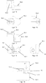
- the tool elements 16.1 and 16.2 are fixed by screwing in the receptacles 14.1 and 14.2, which are arranged in the jaw parts 7.1 and 7.2 of the handle part 2 and the lever arm 4.
- the cutting edges of the tool elements 16.1 and 16.2 are adapted to each other and to the surgical implant 15 in a typical embodiment.
- the tool elements 16.1 and 16.2 also recesses, which serve as a receptacle 19.1 and 19.2 for Federandschreiber 17.1 and 17.2.
- the spring presser 17.1 and 17.2 bending of the implant 15 is prevented during cutting. This is shown in FIG. 19 showing the cutting scheme for a typical embodiment.
- the spring-loaded 17.1 and 17.2 are preferably made of a solid, but elastic and thus deformable silicone.
- the spring contacts 17.1 and 17.2 are fixed in a typical embodiment by the screw in the tool elements 16.1 and 16.2, which fix the tool elements 16.1 and 16.2 in the receptacles 14.1 and 14.2 of the jaw parts 7.1 and 7.2.
Landscapes
- Engineering & Computer Science (AREA)
- Life Sciences & Earth Sciences (AREA)
- Health & Medical Sciences (AREA)
- Mechanical Engineering (AREA)
- Forests & Forestry (AREA)
- Surgery (AREA)
- Orthopedic Medicine & Surgery (AREA)
- Biomedical Technology (AREA)
- Nuclear Medicine, Radiotherapy & Molecular Imaging (AREA)
- Heart & Thoracic Surgery (AREA)
- Medical Informatics (AREA)
- Molecular Biology (AREA)
- Animal Behavior & Ethology (AREA)
- General Health & Medical Sciences (AREA)
- Public Health (AREA)
- Veterinary Medicine (AREA)
- Surgical Instruments (AREA)
Claims (15)
- Pince (1), en particulier pince chirurgicale, avec au moins une partie de poignée (2) et un levier de pression (3) qui est monté de manière pivotante par rapport à la partie de poignée et avec une mâchoire composée de deux parties de mâchoire (7.1, 7.2), dans laquelle à la partie de poignée (2) est prévue l'une des parties de mâchoire (7,1) et dans laquelle entre la partie de poignée (2) et le levier de pression (3) est disposé un bras de levier (4) qui présente la deuxième partie de mâchoire (7.2) et peut être soumis à de la pression par le levier de pression (3) et le bras de levier (4) est monté de manière pivotante par rapport à la partie de poignée (2), dans lequel un élément de roulement (5) est disposé entre le levier de pression (3) et le bras de levier (4) et une force exercée sur le levier de pression (3) peut être transmise par l'intermédiaire de l'élément de roulement (5) au bras de levier (4),
caractérisée par le fait
que le corps de roulement (5) est guidé dans une coulisse (9), la coulisse (9) est placée pour le guidage de l'élément de roulement (5) dans la partie de poignée (2) et/ou dans un couvercle de boîtier (8) et le bras de levier (4) présente un réceptacle concave (20) pour l'élément de roulement (5) avec un rayon intérieur qui est supérieur à un rayon extérieur de l'élément de roulement (5) dans la zone des surfaces de roulement, où ce dernier pivote, en exerçant une force sur le levier de pression (3), autour d'un point de rotation/de pivotement (13.2) et exerce une force sur l'élément de roulement (5) qui peut de ce fait être guidé dans la coulisse (9) en direction du bras de levier (4), d'où le bras de levier (4) commence à pivoter autour d'un point de rotation/de pivotement (13.1) et la partie de mâchoire (7.2) du bras de levier (4) se déplace en direction de la partie de mâchoire (7.1) de la partie de poignée (2), et le montage entre la partie de poignée (2) et le levier de pression (3) et entre la partie de poignée (2) et le bras de levier (4) est un montage libre. - Pince (1) selon la revendication 1, caractérisée par le fait qu'un point de rotation/ de pivotement (13.1) du bras de levier (4) se trouve du côté opposé à la partie de mâchoire (7.2).
- Pince (1) selon l'une des revendications précédentes, caractérisée par le fait qu'un point de rotation/de pivotement (13.2) du levier de pression (3) se trouve du côté orienté vers les parties de mâchoire (7.1, 7.2) du levier de pression (3).
- Pince (1) selon l'une des revendications précédentes, caractérisée par le fait que la partie de poignée (2) est au moins en partie une partie d'un boîtier.
- Pince (1) selon l'une des revendications précédentes, caractérisée par le fait que la partie de poignée (2) présente, à une extrémité du côté de la mâchoire, un réceptacle concave (11.2) pour le levier de pression (3).
- Pince (1) selon l'une des revendications précédentes, caractérisée par le fait que la partie de poignée (2) présente, à une extrémité opposée à la mâchoire, un réceptacle concave (11.1) pour le bras de levier (4).
- Pince (1) selon l'une des revendications précédentes, caractérisée par le fait que la partie de poignée (2) présente, à l'extrémité du côté de la mâchoire, un évidement qui convient pour recevoir le bras de levier (4).
- Pince (1) selon la revendication 7, caractérisée par le fait que l'évidement destiné à recevoir le bras de levier (4) est réalisé sous forme d'un canal fermé (10) en direction d'un axe longitudinal (L) de la partie de poignée (2).
- Pince (1) selon l'une des revendications précédentes, caractérisée par le fait que la partie de poignée (2) présente un évidement d'accrochage (12) qui convient pour recevoir un ressort (6).
- Pince (1) selon l'une des revendications précédentes 1 à 9, caractérisée par le fait que le couvercle de boîtier (8) convient pour fermer le boîtier.
- Pince (1) selon l'une des revendications précédentes, caractérisée par le fait que les parties de mâchoire (7.1, 7.2) sont orientées quasi parallèlement l'une à l'autre.
- Pince (1) selon l'une des revendications précédentes, caractérisée par le fait que les parties de mâchoire (7.1, 7.2) conviennent pour recevoir des éléments d'outil (16.1, 16.2) qui sont interchangeables.
- Pince (1) selon la revendication 12, caractérisée par le fait qu'au moins l'un des éléments d'outil (16.1, 16.2) pour couper des implants présente des broches de réception (18.1, 18.2) pour la réception et la fixation des implants (15).
- Pince (1) selon la revendication 12 ou 13, caractérisée par le fait que les éléments d'outil (16.1, 16.2) pour couper des implants (15) présentent des poussoirs à ressort (17.1, 17.2).
- Pince (1) selon l'une des revendications 12 à 14, caractérisée par le fait que les poussoirs à ressort (17.1, 17.2) dans les éléments d'outil (16.1, 16.2) pour couper des implants (15) sont fixés par les vis dans les éléments d'outil (16.1, 16.2) qui fixent les éléments d'outil (16.1, 16.2) dans la partie de poignée (2) et/ou le bras de levier (4).
Applications Claiming Priority (2)
| Application Number | Priority Date | Filing Date | Title |
|---|---|---|---|
| DE201310105751 DE102013105751A1 (de) | 2013-06-04 | 2013-06-04 | Zange |
| PCT/EP2014/061455 WO2014195295A1 (fr) | 2013-06-04 | 2014-06-03 | Pince |
Publications (2)
| Publication Number | Publication Date |
|---|---|
| EP3003176A1 EP3003176A1 (fr) | 2016-04-13 |
| EP3003176B1 true EP3003176B1 (fr) | 2018-02-07 |
Family
ID=51062776
Family Applications (1)
| Application Number | Title | Priority Date | Filing Date |
|---|---|---|---|
| EP14734747.0A Active EP3003176B1 (fr) | 2013-06-04 | 2014-06-03 | Pince |
Country Status (4)
| Country | Link |
|---|---|
| US (1) | US9751224B2 (fr) |
| EP (1) | EP3003176B1 (fr) |
| DE (1) | DE102013105751A1 (fr) |
| WO (1) | WO2014195295A1 (fr) |
Families Citing this family (1)
| Publication number | Priority date | Publication date | Assignee | Title |
|---|---|---|---|---|
| DE102016105637B3 (de) * | 2016-03-24 | 2017-06-22 | Karl Klappenecker GmbH & Co. KG | Instrument, insbesondere Chirurgisches Instrument |
Family Cites Families (11)
| Publication number | Priority date | Publication date | Assignee | Title |
|---|---|---|---|---|
| US103152A (en) * | 1870-05-17 | Improved bolt-ctttting device | ||
| GB139528A (en) * | 1918-05-10 | 1920-03-11 | George Hutchinson | Improvements in cutting and shearing tools |
| GB1593401A (en) | 1977-05-06 | 1981-07-15 | Nat Res Dev | Handgrip tools |
| DE3743605A1 (de) | 1987-12-22 | 1989-07-06 | Delma Elektro Med App | Chirurgische zange |
| DE9105152U1 (de) * | 1991-04-26 | 1991-09-26 | Josef Heiss Medizintechnik GmbH, 7200 Tuttlingen | Zange zum Schneiden chirurgischer Nägel, Drähte o.dgl. |
| DE20018390U1 (de) * | 2000-10-27 | 2001-01-18 | Wenzler Medizintechnik GmbH, 78665 Frittlingen | Schneidzange |
| DE20207785U1 (de) | 2002-05-17 | 2003-09-25 | GEOMED Medizin-Technik GmbH & Co., 78532 Tuttlingen | Chirurgische Zange |
| US8316549B2 (en) * | 2009-12-09 | 2012-11-27 | Midwest Tool And Cutlery Company | Compound leverage hand tool with interchangeable tool head |
| US8713805B2 (en) * | 2010-07-27 | 2014-05-06 | Milwaukee Electric Tool Corporation | Hand cutting tool |
| DE102011001013A1 (de) | 2011-03-02 | 2012-09-06 | Alexander Merz | Zange zum Schneiden von Werkstücken |
| JP6227325B2 (ja) * | 2013-08-27 | 2017-11-08 | 株式会社貝印刃物開発センター | 鋏 |
-
2013
- 2013-06-04 DE DE201310105751 patent/DE102013105751A1/de not_active Withdrawn
-
2014
- 2014-06-03 WO PCT/EP2014/061455 patent/WO2014195295A1/fr not_active Ceased
- 2014-06-03 EP EP14734747.0A patent/EP3003176B1/fr active Active
- 2014-06-03 US US14/895,574 patent/US9751224B2/en active Active
Also Published As
| Publication number | Publication date |
|---|---|
| DE102013105751A1 (de) | 2014-12-04 |
| EP3003176A1 (fr) | 2016-04-13 |
| US20160257007A1 (en) | 2016-09-08 |
| US9751224B2 (en) | 2017-09-05 |
| WO2014195295A1 (fr) | 2014-12-11 |
Similar Documents
| Publication | Publication Date | Title |
|---|---|---|
| EP2612609B1 (fr) | Instrument médical | |
| DE3709067A1 (de) | Medizinisches, insbesondere chirurgisches instrument | |
| EP1941975A2 (fr) | Pince de serrage destinée au serrage d'outils | |
| EP1996091A2 (fr) | Instrument chirurgical | |
| EP2756825A1 (fr) | Outil à choc pour une révision de prothèse mini-invasive | |
| WO2009098589A1 (fr) | Instrument chirurgical démontable | |
| EP1488749B1 (fr) | Dispositif médical | |
| DE10028896B4 (de) | Medizinisches Instrument | |
| DE2755482C2 (fr) | ||
| DE10136964A1 (de) | Chirurgisches Instrument | |
| DE10111766B4 (de) | Medizinisches Instrument | |
| DE4115937A1 (de) | Chirurgisches schneideinstrument | |
| EP2680773B1 (fr) | Tenailles à couper des pièces | |
| DE19713067C2 (de) | Arthroskopie-Instrument | |
| EP3003176B1 (fr) | Pince | |
| DE102012022573A1 (de) | Medizinisches Instrument | |
| DE3739254A1 (de) | Medizinisches, insbesondere chirurgisches instrument | |
| EP1629785A2 (fr) | Pince médicale | |
| DE102016105637B3 (de) | Instrument, insbesondere Chirurgisches Instrument | |
| EP3621535A1 (fr) | Instrument chirurgical à caractéristiques de fermeture améliorées | |
| DE10353552A1 (de) | Chirurgisches Instrument | |
| DE8704161U1 (de) | Medizinisches, insbesondere chirurgisches Instrument | |
| EP2965701B1 (fr) | Pince à tige | |
| EP2545866B1 (fr) | Instrument médical coupant pour couper des muscles et des tendons | |
| EP2226028B1 (fr) | Instrument de coupe chirurgical |
Legal Events
| Date | Code | Title | Description |
|---|---|---|---|
| PUAI | Public reference made under article 153(3) epc to a published international application that has entered the european phase |
Free format text: ORIGINAL CODE: 0009012 |
|
| 17P | Request for examination filed |
Effective date: 20151130 |
|
| AK | Designated contracting states |
Kind code of ref document: A1 Designated state(s): AL AT BE BG CH CY CZ DE DK EE ES FI FR GB GR HR HU IE IS IT LI LT LU LV MC MK MT NL NO PL PT RO RS SE SI SK SM TR |
|
| AX | Request for extension of the european patent |
Extension state: BA ME |
|
| DAX | Request for extension of the european patent (deleted) | ||
| GRAP | Despatch of communication of intention to grant a patent |
Free format text: ORIGINAL CODE: EPIDOSNIGR1 |
|
| INTG | Intention to grant announced |
Effective date: 20170421 |
|
| GRAS | Grant fee paid |
Free format text: ORIGINAL CODE: EPIDOSNIGR3 |
|
| GRAA | (expected) grant |
Free format text: ORIGINAL CODE: 0009210 |
|
| AK | Designated contracting states |
Kind code of ref document: B1 Designated state(s): AL AT BE BG CH CY CZ DE DK EE ES FI FR GB GR HR HU IE IS IT LI LT LU LV MC MK MT NL NO PL PT RO RS SE SI SK SM TR |
|
| REG | Reference to a national code |
Ref country code: GB Ref legal event code: FG4D Free format text: NOT ENGLISH |
|
| REG | Reference to a national code |
Ref country code: AT Ref legal event code: REF Ref document number: 968484 Country of ref document: AT Kind code of ref document: T Effective date: 20180215 Ref country code: CH Ref legal event code: EP |
|
| REG | Reference to a national code |
Ref country code: IE Ref legal event code: FG4D Free format text: LANGUAGE OF EP DOCUMENT: GERMAN |
|
| REG | Reference to a national code |
Ref country code: DE Ref legal event code: R096 Ref document number: 502014007204 Country of ref document: DE |
|
| REG | Reference to a national code |
Ref country code: NL Ref legal event code: MP Effective date: 20180207 |
|
| REG | Reference to a national code |
Ref country code: FR Ref legal event code: PLFP Year of fee payment: 5 |
|
| PG25 | Lapsed in a contracting state [announced via postgrant information from national office to epo] |
Ref country code: FI Free format text: LAPSE BECAUSE OF FAILURE TO SUBMIT A TRANSLATION OF THE DESCRIPTION OR TO PAY THE FEE WITHIN THE PRESCRIBED TIME-LIMIT Effective date: 20180207 Ref country code: NO Free format text: LAPSE BECAUSE OF FAILURE TO SUBMIT A TRANSLATION OF THE DESCRIPTION OR TO PAY THE FEE WITHIN THE PRESCRIBED TIME-LIMIT Effective date: 20180507 Ref country code: LT Free format text: LAPSE BECAUSE OF FAILURE TO SUBMIT A TRANSLATION OF THE DESCRIPTION OR TO PAY THE FEE WITHIN THE PRESCRIBED TIME-LIMIT Effective date: 20180207 Ref country code: HR Free format text: LAPSE BECAUSE OF FAILURE TO SUBMIT A TRANSLATION OF THE DESCRIPTION OR TO PAY THE FEE WITHIN THE PRESCRIBED TIME-LIMIT Effective date: 20180207 Ref country code: ES Free format text: LAPSE BECAUSE OF FAILURE TO SUBMIT A TRANSLATION OF THE DESCRIPTION OR TO PAY THE FEE WITHIN THE PRESCRIBED TIME-LIMIT Effective date: 20180207 Ref country code: NL Free format text: LAPSE BECAUSE OF FAILURE TO SUBMIT A TRANSLATION OF THE DESCRIPTION OR TO PAY THE FEE WITHIN THE PRESCRIBED TIME-LIMIT Effective date: 20180207 Ref country code: CY Free format text: LAPSE BECAUSE OF FAILURE TO SUBMIT A TRANSLATION OF THE DESCRIPTION OR TO PAY THE FEE WITHIN THE PRESCRIBED TIME-LIMIT Effective date: 20180207 |
|
| PG25 | Lapsed in a contracting state [announced via postgrant information from national office to epo] |
Ref country code: GR Free format text: LAPSE BECAUSE OF FAILURE TO SUBMIT A TRANSLATION OF THE DESCRIPTION OR TO PAY THE FEE WITHIN THE PRESCRIBED TIME-LIMIT Effective date: 20180508 Ref country code: IS Free format text: LAPSE BECAUSE OF FAILURE TO SUBMIT A TRANSLATION OF THE DESCRIPTION OR TO PAY THE FEE WITHIN THE PRESCRIBED TIME-LIMIT Effective date: 20180607 Ref country code: PL Free format text: LAPSE BECAUSE OF FAILURE TO SUBMIT A TRANSLATION OF THE DESCRIPTION OR TO PAY THE FEE WITHIN THE PRESCRIBED TIME-LIMIT Effective date: 20180207 Ref country code: LV Free format text: LAPSE BECAUSE OF FAILURE TO SUBMIT A TRANSLATION OF THE DESCRIPTION OR TO PAY THE FEE WITHIN THE PRESCRIBED TIME-LIMIT Effective date: 20180207 Ref country code: SE Free format text: LAPSE BECAUSE OF FAILURE TO SUBMIT A TRANSLATION OF THE DESCRIPTION OR TO PAY THE FEE WITHIN THE PRESCRIBED TIME-LIMIT Effective date: 20180207 Ref country code: RS Free format text: LAPSE BECAUSE OF FAILURE TO SUBMIT A TRANSLATION OF THE DESCRIPTION OR TO PAY THE FEE WITHIN THE PRESCRIBED TIME-LIMIT Effective date: 20180207 Ref country code: BG Free format text: LAPSE BECAUSE OF FAILURE TO SUBMIT A TRANSLATION OF THE DESCRIPTION OR TO PAY THE FEE WITHIN THE PRESCRIBED TIME-LIMIT Effective date: 20180507 |
|
| PG25 | Lapsed in a contracting state [announced via postgrant information from national office to epo] |
Ref country code: MT Free format text: LAPSE BECAUSE OF FAILURE TO SUBMIT A TRANSLATION OF THE DESCRIPTION OR TO PAY THE FEE WITHIN THE PRESCRIBED TIME-LIMIT Effective date: 20180207 |
|
| PG25 | Lapsed in a contracting state [announced via postgrant information from national office to epo] |
Ref country code: EE Free format text: LAPSE BECAUSE OF FAILURE TO SUBMIT A TRANSLATION OF THE DESCRIPTION OR TO PAY THE FEE WITHIN THE PRESCRIBED TIME-LIMIT Effective date: 20180207 Ref country code: AL Free format text: LAPSE BECAUSE OF FAILURE TO SUBMIT A TRANSLATION OF THE DESCRIPTION OR TO PAY THE FEE WITHIN THE PRESCRIBED TIME-LIMIT Effective date: 20180207 Ref country code: IT Free format text: LAPSE BECAUSE OF FAILURE TO SUBMIT A TRANSLATION OF THE DESCRIPTION OR TO PAY THE FEE WITHIN THE PRESCRIBED TIME-LIMIT Effective date: 20180207 Ref country code: RO Free format text: LAPSE BECAUSE OF FAILURE TO SUBMIT A TRANSLATION OF THE DESCRIPTION OR TO PAY THE FEE WITHIN THE PRESCRIBED TIME-LIMIT Effective date: 20180207 |
|
| REG | Reference to a national code |
Ref country code: DE Ref legal event code: R097 Ref document number: 502014007204 Country of ref document: DE |
|
| PG25 | Lapsed in a contracting state [announced via postgrant information from national office to epo] |
Ref country code: CZ Free format text: LAPSE BECAUSE OF FAILURE TO SUBMIT A TRANSLATION OF THE DESCRIPTION OR TO PAY THE FEE WITHIN THE PRESCRIBED TIME-LIMIT Effective date: 20180207 Ref country code: DK Free format text: LAPSE BECAUSE OF FAILURE TO SUBMIT A TRANSLATION OF THE DESCRIPTION OR TO PAY THE FEE WITHIN THE PRESCRIBED TIME-LIMIT Effective date: 20180207 Ref country code: SM Free format text: LAPSE BECAUSE OF FAILURE TO SUBMIT A TRANSLATION OF THE DESCRIPTION OR TO PAY THE FEE WITHIN THE PRESCRIBED TIME-LIMIT Effective date: 20180207 Ref country code: SK Free format text: LAPSE BECAUSE OF FAILURE TO SUBMIT A TRANSLATION OF THE DESCRIPTION OR TO PAY THE FEE WITHIN THE PRESCRIBED TIME-LIMIT Effective date: 20180207 |
|
| PLBE | No opposition filed within time limit |
Free format text: ORIGINAL CODE: 0009261 |
|
| STAA | Information on the status of an ep patent application or granted ep patent |
Free format text: STATUS: NO OPPOSITION FILED WITHIN TIME LIMIT |
|
| 26N | No opposition filed |
Effective date: 20181108 |
|
| GBPC | Gb: european patent ceased through non-payment of renewal fee |
Effective date: 20180603 |
|
| PG25 | Lapsed in a contracting state [announced via postgrant information from national office to epo] |
Ref country code: SI Free format text: LAPSE BECAUSE OF FAILURE TO SUBMIT A TRANSLATION OF THE DESCRIPTION OR TO PAY THE FEE WITHIN THE PRESCRIBED TIME-LIMIT Effective date: 20180207 |
|
| REG | Reference to a national code |
Ref country code: BE Ref legal event code: MM Effective date: 20180630 |
|
| REG | Reference to a national code |
Ref country code: IE Ref legal event code: MM4A |
|
| PG25 | Lapsed in a contracting state [announced via postgrant information from national office to epo] |
Ref country code: LU Free format text: LAPSE BECAUSE OF NON-PAYMENT OF DUE FEES Effective date: 20180603 Ref country code: MC Free format text: LAPSE BECAUSE OF FAILURE TO SUBMIT A TRANSLATION OF THE DESCRIPTION OR TO PAY THE FEE WITHIN THE PRESCRIBED TIME-LIMIT Effective date: 20180207 |
|
| PG25 | Lapsed in a contracting state [announced via postgrant information from national office to epo] |
Ref country code: GB Free format text: LAPSE BECAUSE OF NON-PAYMENT OF DUE FEES Effective date: 20180603 Ref country code: IE Free format text: LAPSE BECAUSE OF NON-PAYMENT OF DUE FEES Effective date: 20180603 |
|
| PG25 | Lapsed in a contracting state [announced via postgrant information from national office to epo] |
Ref country code: BE Free format text: LAPSE BECAUSE OF NON-PAYMENT OF DUE FEES Effective date: 20180630 |
|
| PG25 | Lapsed in a contracting state [announced via postgrant information from national office to epo] |
Ref country code: TR Free format text: LAPSE BECAUSE OF FAILURE TO SUBMIT A TRANSLATION OF THE DESCRIPTION OR TO PAY THE FEE WITHIN THE PRESCRIBED TIME-LIMIT Effective date: 20180207 |
|
| PG25 | Lapsed in a contracting state [announced via postgrant information from national office to epo] |
Ref country code: PT Free format text: LAPSE BECAUSE OF FAILURE TO SUBMIT A TRANSLATION OF THE DESCRIPTION OR TO PAY THE FEE WITHIN THE PRESCRIBED TIME-LIMIT Effective date: 20180207 |
|
| PG25 | Lapsed in a contracting state [announced via postgrant information from national office to epo] |
Ref country code: HU Free format text: LAPSE BECAUSE OF FAILURE TO SUBMIT A TRANSLATION OF THE DESCRIPTION OR TO PAY THE FEE WITHIN THE PRESCRIBED TIME-LIMIT; INVALID AB INITIO Effective date: 20140603 Ref country code: MK Free format text: LAPSE BECAUSE OF NON-PAYMENT OF DUE FEES Effective date: 20180207 |
|
| REG | Reference to a national code |
Ref country code: AT Ref legal event code: MM01 Ref document number: 968484 Country of ref document: AT Kind code of ref document: T Effective date: 20190603 |
|
| PG25 | Lapsed in a contracting state [announced via postgrant information from national office to epo] |
Ref country code: AT Free format text: LAPSE BECAUSE OF NON-PAYMENT OF DUE FEES Effective date: 20190603 |
|
| PGFP | Annual fee paid to national office [announced via postgrant information from national office to epo] |
Ref country code: FR Payment date: 20250623 Year of fee payment: 12 |
|
| PGFP | Annual fee paid to national office [announced via postgrant information from national office to epo] |
Ref country code: DE Payment date: 20250827 Year of fee payment: 12 |
|
| PGFP | Annual fee paid to national office [announced via postgrant information from national office to epo] |
Ref country code: CH Payment date: 20250701 Year of fee payment: 12 |