EP3002606A1 - Appareil, système et procédé de détection d'état d'espace sur la base d'un signal acoustique - Google Patents
Appareil, système et procédé de détection d'état d'espace sur la base d'un signal acoustique Download PDFInfo
- Publication number
- EP3002606A1 EP3002606A1 EP15176006.3A EP15176006A EP3002606A1 EP 3002606 A1 EP3002606 A1 EP 3002606A1 EP 15176006 A EP15176006 A EP 15176006A EP 3002606 A1 EP3002606 A1 EP 3002606A1
- Authority
- EP
- European Patent Office
- Prior art keywords
- signal
- characteristic parameter
- space
- space status
- acoustic signal
- Prior art date
- Legal status (The legal status is an assumption and is not a legal conclusion. Google has not performed a legal analysis and makes no representation as to the accuracy of the status listed.)
- Ceased
Links
Images


Classifications
-
- G—PHYSICS
- G01—MEASURING; TESTING
- G01S—RADIO DIRECTION-FINDING; RADIO NAVIGATION; DETERMINING DISTANCE OR VELOCITY BY USE OF RADIO WAVES; LOCATING OR PRESENCE-DETECTING BY USE OF THE REFLECTION OR RERADIATION OF RADIO WAVES; ANALOGOUS ARRANGEMENTS USING OTHER WAVES
- G01S15/00—Systems using the reflection or reradiation of acoustic waves, e.g. sonar systems
- G01S15/02—Systems using the reflection or reradiation of acoustic waves, e.g. sonar systems using reflection of acoustic waves
- G01S15/04—Systems determining presence of a target
-
- G—PHYSICS
- G01—MEASURING; TESTING
- G01S—RADIO DIRECTION-FINDING; RADIO NAVIGATION; DETERMINING DISTANCE OR VELOCITY BY USE OF RADIO WAVES; LOCATING OR PRESENCE-DETECTING BY USE OF THE REFLECTION OR RERADIATION OF RADIO WAVES; ANALOGOUS ARRANGEMENTS USING OTHER WAVES
- G01S15/00—Systems using the reflection or reradiation of acoustic waves, e.g. sonar systems
- G01S15/02—Systems using the reflection or reradiation of acoustic waves, e.g. sonar systems using reflection of acoustic waves
- G01S15/50—Systems of measurement, based on relative movement of the target
- G01S15/52—Discriminating between fixed and moving objects or between objects moving at different speeds
- G01S15/523—Discriminating between fixed and moving objects or between objects moving at different speeds for presence detection
-
- G—PHYSICS
- G01—MEASURING; TESTING
- G01S—RADIO DIRECTION-FINDING; RADIO NAVIGATION; DETERMINING DISTANCE OR VELOCITY BY USE OF RADIO WAVES; LOCATING OR PRESENCE-DETECTING BY USE OF THE REFLECTION OR RERADIATION OF RADIO WAVES; ANALOGOUS ARRANGEMENTS USING OTHER WAVES
- G01S15/00—Systems using the reflection or reradiation of acoustic waves, e.g. sonar systems
- G01S15/88—Sonar systems specially adapted for specific applications
-
- G—PHYSICS
- G01—MEASURING; TESTING
- G01S—RADIO DIRECTION-FINDING; RADIO NAVIGATION; DETERMINING DISTANCE OR VELOCITY BY USE OF RADIO WAVES; LOCATING OR PRESENCE-DETECTING BY USE OF THE REFLECTION OR RERADIATION OF RADIO WAVES; ANALOGOUS ARRANGEMENTS USING OTHER WAVES
- G01S7/00—Details of systems according to groups G01S13/00, G01S15/00, G01S17/00
- G01S7/52—Details of systems according to groups G01S13/00, G01S15/00, G01S17/00 of systems according to group G01S15/00
- G01S7/523—Details of pulse systems
- G01S7/526—Receivers
- G01S7/527—Extracting wanted echo signals
-
- G—PHYSICS
- G08—SIGNALLING
- G08B—SIGNALLING OR CALLING SYSTEMS; ORDER TELEGRAPHS; ALARM SYSTEMS
- G08B13/00—Burglar, theft or intruder alarms
- G08B13/16—Actuation by interference with mechanical vibrations in air or other fluid
- G08B13/1654—Actuation by interference with mechanical vibrations in air or other fluid using passive vibration detection systems
- G08B13/1672—Actuation by interference with mechanical vibrations in air or other fluid using passive vibration detection systems using sonic detecting means, e.g. a microphone operating in the audio frequency range
Definitions
- the disclosure relates to space status detection, and particularly relates to an apparatus, a system and a method for space status detection based on acoustic signal.
- the disclosure is directed to an apparatus, a system and a method for space status detection based on an acoustic signal.
- the disclosure provides a space status detection apparatus based on acoustic signal, which includes an audio transmitting device, an audio receiving device, a signal processing device and a decision device.
- the audio transmitting device transmits an acoustic signal into a space.
- the audio receiving device receives a varied acoustic signal that the transmitted acoustic signal is varied in the space to serve as a sensing signal.
- the signal processing device coupled to the audio receiving device receives the sensing signal and generates a characteristic parameter of a space status according to the sensing signal.
- the decision device is coupled to the signal processing device to receive the characteristic parameter and detects a change of the space status according to the characteristic parameter.
- the disclosure provides a space status detection system based on acoustic signal including the aforementioned space status detection apparatus, and further including an electronic device and a network device.
- the space status detection apparatus detects that the space status is changed, the space status detection apparatus transmits a message to the electronic device through the network device.
- the disclosure provides a method for space status detection based on acoustic signal.
- An acoustic signal is transmitted into a space, and a varied acoustic signal that the transmitted acoustic signal is varied in the space is received to serve as an sensing signal.
- a characteristic parameter is obtained according to the sensing signal.
- a changes of the space status is detected according to the characteristic parameter.
- FIG. 1 is a block schematic diagram of a space status detection apparatus 1000 based on acoustic signal according to an embodiment of a disclosure.
- the space status detection apparatus 1000 based on acoustic signal includes an audio transmitting device 1200, an audio receiving device 1400, a signal processing device 1600 and a decision device 1800.
- the audio transmitting device 1200 transmits an acoustic signal AS_T into a space (not shown).
- the audio receiving device 1400 receives a varied acoustic signal AS_R of the acoustic signal AS_T varied in the space to serve as an audio sensing signal AS.
- the signal processing device 1600 receives the audio sensing signal AS transmitted by the audio receiving device 1400, and generates a space status characteristic parameter SSCP according to the audio sensing signal AS.
- the decision device 1800 receives the space status characteristic parameter SSCP transmitted by the signal processing device 1600, and detects changes of a space status in different times according to the space status characteristic parameter SSCP.
- the audio transmitting device 1200 can be a speaker, and the audio receiving device 1400 can be a microphone, though the disclosure is not limited thereto. Any element capable of sending sound and receiving sound can be used as the audio transmitting device 1200 and the audio receiving device 140 of the disclosure.
- the signal processing device 1600 and the decision device 1800 can be hardware, firmware, or software or machine executable program codes stored in a memory and loaded and executed by a processor or microprocessor. If hardware or circuits are adopted for implementation, each of the signal processing device 1600 and the decision device 1800 can be implemented by a circuit chip, or can be partially or entirely implemented by a single integrated circuit chip, though the disclosure is not limited thereto.
- the aforementioned memory can be an optical disk, a random access memory (RAM), a read only memory (ROM), a flash memory, a floppy disk, a hard disk or a magnetic optical disk, or a remote recording medium or a none-temporary machine readable medium that can be accessed through a network.
- the aforementioned hardware is, for example, implemented by a general computer, an application specific integrated circuit (ASIC) or a field programmable gate array (FPGA).
- ASIC application specific integrated circuit
- FPGA field programmable gate array
- the hardware may include a memory device.
- the memory device is, for example, a RAM, a ROM, a flash memory, a thumb disk, etc., which is used for storing the aforementioned software or the machine executable program codes.
- the space where the space status detection apparatus 1000 is installed can be an indoor space
- the acoustic signal AS_T sent by the audio transmitting device 1200 can be an impulse
- the varied acoustic signal AS_R received by the audio receiving device 1400 can be an impulse response of the impulse in the space, though the disclosure is not limited thereto.
- the acoustic signal AS_T sent by the audio transmitting device 1200 can be an audible sound wave, where a frequency range of the audible sound wave is about 20Hz-20kHz, though the disclosure is not limited thereto.
- the acoustic signal AS_T sent by the audio transmitting device 1200 can be an ultrasonic wave with a frequency more than 20kHz or an infrasonic wave with a frequency lower than 20Hz.
- the audio transmitting device 1200 can periodically or non-periodically (for example, randomly) transmit the acoustic signal AS_T into the space, and the signal processing device 1600 can generate the corresponding space status characteristic parameter SSCP.
- the space status detection apparatus 1000 can be installed in an indoor space.
- the space status detection apparatus 1000 sets the audio transmitting device 1200 to transmit the impulse AS_T into the indoor space.
- the audio receiving device 1400 receives the impulse response AS_R in the indoor space to serve as the audio sensing signal AS.
- the signal processing device 1600 generates the space status characteristic parameter SSCP of the initial stage according to a characteristic of the audio sensing signal AS.
- the space status detection apparatus 1000 sets the audio transmitting device 1200 to periodically or non-periodically (for example, randomly) transmit the impulse AS_T into the indoor space, though the disclosure is not limited thereto.
- the audio transmitting device 1200 can also be triggered through other sensing mechanism to transmit the impulse AS_T (acoustic signal), for example, triggered through an infrared manner.
- the audio receiving device 1400 can receive the corresponding impulse response AS_R to serve as the audio sensing signal AS.
- the signal processing device 1600 generates the corresponding space status characteristic parameter SSCP according to the audio sensing signal AS.
- the decision device 1800 compares the corresponding space status characteristic parameter SSCP with the space status characteristic parameter SSCP of the initial stage to detect whether the space status of the space is changed between the initial stage and the detection stage.
- FIG. 2A illustrates an impulse response in a small room according to an embodiment of the disclosure.
- FIG. 2B illustrates an impulse response in a large room according to an embodiment of the disclosure.
- FIG. 2C is a peak comparison diagram of impulse amplitude distributions in rooms with different sizes according to an embodiment of the disclosure.
- FIG. 2D is an energy spectrum diagram of impulse response in an empty room according to an embodiment of the disclosure.
- FIG. 2E is an energy spectrum diagram of impulse response in a room arranged with articles according to an embodiment of the disclosure. According to FIG. 2A-FIG.
- the varied acoustic signal AS_R received by the audio receiving device 1400 can be represented by a model, and the model can be a transform of the acoustic signal AS_T transmitted by the audio transmitting device 1200 in the indoor space.
- x[n] is the acoustic signal AS_T transmitted by the audio transmitting device 1200
- ⁇ frequency
- x[n] the impulse (i.e. ⁇ [n])
- X( ⁇ ) thereof is equal to 1
- the frequency response Y( ⁇ ) of the varied acoustic signal AS_R received by the audio receiving device 1400 is the frequency response H( ⁇ ) of the indoor space.
- the varied acoustic signal AS_R received by the audio receiving device 1400 is the characteristic of the indoor space.
- the space status detection apparatus 1000 is disposed in the indoor space, the audio transmitting device 1200 is configured to transmit an impulse, and the audio receiving device 1400 is configured to receive the impulse response AS_R in the indoor space to serve as the audio sensing signal AS, the disclosure is not limited thereto.
- the space status detection apparatus 1000 can be disposed in an outdoor space, the audio transmitting device 1200 is configured to transmit any type of the acoustic signal AS_T, and the audio receiving device 1400 is configured to receive the varied acoustic signal AS_R of the acoustic signal AS_T in the outdoor space to serve as the audio sensing signal AS.
- configuration of the space status detection apparatus 1000 can be determined according to an actual design/application requirement.
- FIG. 3 is a block schematic diagram of a signal processing device 1600 of the embodiment of FIG. 1 according to an embodiment of the disclosure.
- the signal processing device 1600 includes a signal extracting unit 2620 and a first calculation unit 2640.
- the signal extracting unit 2620 receives the audio sensing signal AS and extracts a valid signal VS in the audio sensing signal AS.
- the first calculation unit 2640 receives the valid signal VS from the signal extracting unit 2620, and calculates the space status characteristic parameter SSCP according to the valid signal VS.
- the signal extracting unit 2620 may extract a section of the audio sensing signal AS having the acoustic signal variation.
- the impulse response of the indoor space is taken as an example for description, though the disclosure is not limited thereto.
- FIG. 4 is a schematic diagram of signal extraction of the impulse response according to an embodiment of the disclosure.
- the signal processing device 1600 receives three audio sensing signals AS1, AS2 and AS3 within 6 seconds.
- sections 401, 402 and 403 having the acoustic signal variation in the three audio sensing signals AS1, AS2 and AS3 are only maintained by 25 ms, respectively.
- the signal extracting unit 2620 can extract the audio sensing signals in the sections 401, 402 and 403, and provide the audio sensing signals in the sections 401, 402 and 403 to the first calculation unit 2640 to calculate the space status characteristic parameters SSCP. In this way, the signal processing amount of the first calculation unit 2640 is decreased.
- the signal processing device 1600 receives the three audio sensing signals AS1, AS2 and AS3 within 6 seconds, and the sections 401, 402 and 403 having the acoustic signal variation in the three audio sensing signals AS1, AS2 and AS3 are maintained by 25 ms respectively, though the disclosure is not limited thereto. Namely, the section having the acoustic signal variation in each audio sensing signal (for example, the audio sensing signal AS1) can be maintained shorter, and can also be maintained till a next audio sensing signal (for example, the audio sensing signal AS2) is received. A length of the section having the acoustic signal variation in each audio sensing signal can be varied along with the space where the space status detection apparatus 1000 is disposed. An interval that the signal processing device 1600 receives each of the audio sensing signals (i.e. an interval that the audio transmitting device 1200 transmits each acoustic signal) can be determined according to an actual design requirement.
- the audio sensing signal AS received by the signal extracting unit 2620 may include a direction sound section and a reflection section, where the direct sound section represents the signal without being reflected in the space, and the reflection section may include early reflections and reverberations.
- the impulse response of the indoor space is taken as an example for description, though the disclosure is not limited thereto.
- FIG. 5 is an impulse response diagram of an indoor space according to an embodiment of the disclosure.
- the response signal in a region 501 can be regarded as a direct impulse without being reflected in the indoor space, which has a maximum sound pressure.
- a region 502 can be regarded as the impulse of early reflections in the indoor space, and since the impulse may have energy loss during the reflection, the sound pressure thereof is smaller than that of the direct impulse.
- a region 503 can be regarded as the impulse of reverberations in the indoor space, and the sound pressure thereof is further decreased along with time increase.
- the signal extracting unit 2620 can filter the direct sound in the audio sensing signal AS, though the disclosure is not limited thereto. In other embodiments of the disclosure, the signal extracting unit 2620 can also filter the reflection sound in the audio sensing signal AS, which is determined according to an actual design/application requirement.
- FIG. 6 is a block schematic diagram of the signal extracting unit 2620 of the embodiment of FIG. 3 according to an embodiment of the disclosure.
- the signal extracting unit 2620 includes an amplitude calculation unit 3622 and a sound filter unit 3624.
- the amplitude calculation unit 3622 receives the audio sensing signal AS to calculate an average amplitude of the audio sensing signal AS, and outputs an average amplitude value AMP.
- the sound filter unit 3624 receives the audio sensing signal AS, and is coupled to the amplitude calculation unit 3622 to receive the average amplitude value AMP, and filters the audio sensing signal AS according to the average amplitude value AMP to generate the valid signal VS.
- the sound filter unit 3624 can be used to filter the direct sound section in the audio sensing signal AS.
- the sound filter unit 3624 determines whether the amplitude of the audio sensing signal AS keeps being smaller than the average amplitude value AMP by a predetermined time T, and if the determination result is affirmative, the sound filter unit 3624 outputs the audio sensing signal after the predetermined time T to serve as the valid signal VS, and otherwise filters the audio sensing signal before the predetermined time T, though the disclosure is not limited thereto. Namely, the sound filter unit 3624 can also filter the reflection section in the audio sensing signal AS.
- the sound filter unit 3624 determines whether the amplitude of the audio sensing signal AS keeps being smaller than the average amplitude value AMP by the predetermined time T, and if the determination result is affirmative, the sound filter unit 3624 filters the audio sensing signal after the predetermined time T, and otherwise outputs the audio sensing signal before the predetermined time T to serve as the valid signal VS.
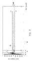
- FIG. 7 is an impulse response diagram according to an embodiment of the disclosure.
- the amplitude calculation unit 3622 calculates the average amplitude value AMP of the received audio sensing signal AS, which is shown by dot lines L1 and L2 in FIG. 7 , where the dot line L1 represents a positive value of the average amplitude value AMP, and the dot line L2 represents a negative value of the average amplitude value AMP.
- the sound filter unit 3624 determines the audio sensing signal AS within such time interval to be the direct sound section DS. After the time point t1, the absolute value of the amplitude value of the audio sensing signal AS keeps being smaller than the average amplitude value AMP.
- the sound filter unit 3624 determines the audio sensing signal after the time point t2 to be the reflection section RS, and determines the audio sensing signal before the time point t2 to be the direct sound section DS. In this way, the sound filter unit 3624 can determine to output the direct sound section DS or the reflection section RS to serve as the valid signal VS according to an actual design/application requirement.
- the first calculation unit 2640 shown in FIG. 3 can generate at least one characteristic parameter according to the valid signal VS, and outputs the space status characteristic parameter SSCP.
- the space status characteristic parameter SSCP may include the at least one parameter or a statistic amount of the at least one parameter, though the disclosure is not limited thereto.
- the at least one characteristic parameter generated by the first calculation unit 2640 may include frequency domain characteristic parameters or time domain characteristic parameters.
- the first calculation unit 2640 may calculate an expectation value or a standard deviation of the frequency domain characteristic parameters or calculate an expectation value or a standard deviation of the time domain characteristic parameters.
- the first calculation unit 2640 takes the expectation value or the standard deviation of the frequency domain characteristic parameters or the expectation value or the standard deviation of the time domain characteristic parameters as the statistic amount of the at least one parameter.
- the first calculation unit 2640 can merge the expectation value and the standard deviation of the frequency domain characteristic parameters to serve as the statistic amount of the at least one characteristic parameter.
- the first calculation unit 2640 can also merge the expectation value and the standard deviation of the time domain characteristic parameters to serve as the statistic amount of the at least one characteristic parameter.
- the first calculation unit 2640 can also merge the expectation value and the standard deviation of the time domain characteristic parameters and the expectation value and the standard deviation of the frequency domain characteristic parameters to serve as the statistic amount of the at least one characteristic parameter, though the disclosure is not limited thereto.
- the frequency domain characteristic parameters can be used to obtain a spectrum characteristic of the valid signal VS by using MPEG7 spectral descriptors, as shown in FIG. 8A.
- FIG. 8A is a schematic diagram of frequency domain characteristic of the valid signal VS according to an embodiment of the disclosure.
- the spectrum characteristic may include audio spectrum envelop (ASE), audio spectrum centroid (ASC), audio spectrum spread (ASS), audio spectrum flatness (ASF) or audio spectrum bandwidth.
- the ASE is to describe the original signal through a log-frequency, by which a data amount of the original signal can be decreased.
- the ASC can represent a shape of a power spectrum, which can be used to determine whether the power spectrum is mainly composed of a high frequency signal or a low frequency signal.
- the ASS can represent a shape of the spectrum, which can be used to represent a distribution of the spectrum around the centroid.
- a low value of the ASS represents that the spectrum is focused at the centroid, and a high value of the ASS represents that the spectrum is spread.
- the ASF represents a flatness of the power spectrum, which can be used to determine whether a signal is an interference caused by noise.
- the high value of the ASF represents that the signal is noise, and otherwise the signal is regarded to have a harmonic structure.
- the time domain characteristic parameters may include partial energy of the amplitude of the valid signal VS, peak statistic of the amplitude of the valid signal VS or a reverberation time (RT) of the space, as shown in FIG. 8B.
- FIG. 8B is a schematic diagram of time domain characteristic of the valid signal VS according to an embodiment of the disclosure.
- FIG. 8B illustrates the partial energy of the amplitude of the valid signal VS and the reverberation time RT of the space, where the reverberation time RT represents a time required for attenuation of the stable sound pressure by 60dB.
- the time domain characteristic parameters can effectively reflect information such as a volume of the space and a wall reflection distance, etc.
- FIG. 9A-FIG. 9C are flow schematic diagrams of the space status characteristic parameters in the initial stage according to an embodiment of the disclosure.
- the first calculation unit 2640 receives the valid signal VS, as shown in FIG. 9A .
- the valid signal VS can be an impulse response, though the disclosure is not limited thereto.
- the first calculation unit 2640 calculates an average amplitude value AMP_INI of the valid signal VS in the initial stage, and subtracts the amplitude of the valid signal VS by the average amplitude value AMP_INI of the initial stage to produce a first difference signal DVS1 shown in FIG. 9B .
- the first calculation unit 2640 obtains an absolute value of the first difference signal DVS1 to generate a first absolute difference signal ADVS1, and divides the first absolute difference signal ADVS1 into a plurality of frames to calculate a partial energy value of each frame, as shown in FIG. 9C . Finally, the partial energy values are computed to obtain the space status characteristic parameter of the initial stage.
- FIG. 10A-FIG. 10C are flow schematic diagrams of the space status characteristic parameters in the detection stage according to an embodiment of the disclosure.
- the first calculation unit 2640 receives the valid signal VS, as shown in FIG. 10A .
- the valid signal VS can be an impulse response, though the disclosure is not limited thereto.
- the first calculation unit 2640 subtracts the amplitude of the valid signal VS by the average amplitude value AMP_INI of the initial stage to produce a second difference signal DVS2 shown in FIG. 10B .
- the first calculation unit 2640 obtains an absolute value of the second difference signal DVS2 to generate a second absolute difference signal ADVS2, and divides the second absolute difference signal ADVS2 into a plurality of frames to calculate a partial energy value of each frame, as shown in FIG. 10C . Finally, the partial energy values are computed to obtain the space status characteristic parameter of the detection stage.
- FIG. 11 is a block schematic diagram of the decision device 1800 of the embodiment of FIG. 1 .
- the space status detection apparatus 1000 may include an initial mode and a detection mode.
- the decision device 1800 includes a setting unit 5820 and a determination unit 5840.
- the setting unit 5820 receives the space status characteristic parameter SSCP corresponding to the initial mode, and determines a threshold TH according to the space status characteristic parameter SSCP.
- the determination unit 5840 is coupled to the setting unit 5820 to receive the threshold TH.
- the determination unit 5840 receives the space status characteristic parameter SSCP corresponding to the detection mode, and determines whether the space status is changed according to the threshold TH and the space status characteristic parameter SSCP corresponding to the detection mode, and accordingly generates a message MSG.
- the setting unit 5820 calculates an expectation value and a standard deviation of the frame partial energy value of the first absolute difference signal ADVS1, and sets the threshold TH as a sum of the expectation value and twice of the standard deviation, where the expectation value is, for example, an average of the frame partial energy value.
- the setting unit 5820 calculates an expectation value of the frame partial energy value of the second absolute difference signal ADVS2, and compares the expectation value with the threshold TH. If the expectation value of the frame partial energy value of the second absolute difference signal ADVS2 is greater than the threshold TH, it represents that the space status is changed, and otherwise represents that the space status is in a normal status.
- the disclosure is not limited thereto.
- the setting unit 5820 can also set the threshold TH according to the Z-test or the Euclidean distance. It should be noticed that according to the test result of the present embodiment, to set the threshold TH according to the Euclidean distance can greatly reduce a chance of misjudgement of the space status detection apparatus 1000.
- FIG. 12 is a histogram of a space status comparison result according to an embodiment of the disclosure.
- the space status comparison result has 28 test samples, where in the test samples 1-8, the test space is maintained to the initial stage, and in the test samples 9-28, the test space is added with other objects.
- Values of the space status characteristic parameters SSCP of the test samples 1-8 are all smaller than the threshold TH, such that the space status detection apparatus 1000 determines that the space status of the test samples 1-8 is the normal status.
- Values of the space status characteristic parameters SSCP of the test samples 9-28 are all greater than the threshold TH, such that the space status detection apparatus 1000 determines that the space status of the test samples 9-28 is an abnormal status, and generates a message MSG for subsequent use.
- FIG. 13 is a block schematic diagram of a space status detection system 100 based on acoustic signal according to an embodiment of the disclosure.
- the space status detection system 100 includes an electronic apparatus 9000 and the space status detection apparatus 1000 based on acoustic signal of FIG. 1 .
- the space status detection apparatus 1000 further includes a network device 1900. When the space status detection apparatus 1000 detects that the space status is changed, the space status detection apparatus 1000 sends the message MSG to the electronic apparatus 9000 through the network device 1900.
- the network device 1900 can communicate with the electronic apparatus 9000.
- the network device 1900 supports a communication mechanism, for example, Bluetooth, Wi-Fi, global system for mobile communication (GSM), code division multiple access (CDMA), wideband CDMA (WCDMA), CDMA-2000, time division multiple access (TDMA), worldwide interoperability for microwave access (WiMAX), long term evolution (LTE), wireless local area network (WLAN) or ultra-wideband (UWB).
- GSM global system for mobile communication
- CDMA code division multiple access
- WCDMA wideband CDMA
- TDMA time division multiple access
- WiMAX worldwide interoperability for microwave access
- LTE long term evolution
- WLAN wireless local area network
- UWB ultra-wideband
- the electronic apparatus 9000 can be one of a plurality of computer systems or a mobile device, for example, a personal desktop, a workstation, an ultra-mobile PC (UMPC), a net-book, a portable computer, a tablet, a personal digital assistant (PDA), a wireless phone, a mobile phone, a smart phone, etc.
- UMPC ultra-mobile PC
- PDA personal digital assistant
- FIG. 14 is a flowchart illustrating a method for space status detection based on acoustic signal according to an embodiment of the disclosure.
- the method for space status detection based on acoustic signal includes following steps. First, in step S600, an acoustic signal is transmitted into a space, and a varied acoustic signal which is the transmitted acoustic signal varied in the space is received to serve as an audio sensing signal. Then, in step S620, a space status characteristic parameter is obtained according to the audio sensing signal. Then, in step S640, changes of the space status are detected according to the space status characteristic parameter.
- the audio transmitting device transmits the acoustic signal into the space
- the audio receiving device receives the varied acoustic signal which is the transmitted acoustic signal varied in the space to generate the audio sensing signal, accordingly.
- the space status characteristic parameter is obtained according to the audio sensing signal, and it is detected whether the space status is changed according to the space status characteristic parameter.
- the acoustic signal for example, impulse
- a general speaker and a microphone can be used as the audio transmitting device and the audio receiving device. In this way, the hardware cost of the space status detection apparatus is reduced.
- the acoustic signal can be repeatedly reflected in the space (especially an indoor space) before reception, the problems of signal blind angle and signal transceiving directivity are mitigated.
Applications Claiming Priority (1)
| Application Number | Priority Date | Filing Date | Title |
|---|---|---|---|
| TW103133958A TWI628454B (zh) | 2014-09-30 | 2014-09-30 | 基於聲波的空間狀態偵測裝置、系統與方法 |
Publications (1)
| Publication Number | Publication Date |
|---|---|
| EP3002606A1 true EP3002606A1 (fr) | 2016-04-06 |
Family
ID=53541544
Family Applications (1)
| Application Number | Title | Priority Date | Filing Date |
|---|---|---|---|
| EP15176006.3A Ceased EP3002606A1 (fr) | 2014-09-30 | 2015-07-09 | Appareil, système et procédé de détection d'état d'espace sur la base d'un signal acoustique |
Country Status (4)
| Country | Link |
|---|---|
| US (1) | US9612329B2 (fr) |
| EP (1) | EP3002606A1 (fr) |
| CN (1) | CN105721066B (fr) |
| TW (1) | TWI628454B (fr) |
Cited By (1)
| Publication number | Priority date | Publication date | Assignee | Title |
|---|---|---|---|---|
| EP3264133A1 (fr) * | 2016-06-29 | 2018-01-03 | Industrial Technology Research Institute | Procédé et appareil de détection d'état d'espace sur la base de signaux de compression d'impulsions acoustiques |
Families Citing this family (9)
| Publication number | Priority date | Publication date | Assignee | Title |
|---|---|---|---|---|
| TWI641990B (zh) * | 2017-06-01 | 2018-11-21 | 宏碁股份有限公司 | 行動電子裝置及其模式切換方法 |
| CN109375199B (zh) * | 2017-08-09 | 2022-12-06 | 宏碁股份有限公司 | 距离检测装置及其距离检测方法 |
| US10921446B2 (en) | 2018-04-06 | 2021-02-16 | Microsoft Technology Licensing, Llc | Collaborative mapping of a space using ultrasonic sonar |
| CN109212482A (zh) * | 2018-09-12 | 2019-01-15 | 北京小米移动软件有限公司 | 声波检测方法及装置 |
| CN109633655B (zh) * | 2018-12-29 | 2020-10-16 | 肇庆奥迪威传感科技有限公司 | 超声波测距方法及超声波测距装置 |
| US10943602B2 (en) * | 2019-01-07 | 2021-03-09 | Stmicroelectronics International N.V. | Open vs enclosed spatial environment classification for a mobile or wearable device using microphone and deep learning method |
| US11308979B2 (en) | 2019-01-07 | 2022-04-19 | Stmicroelectronics, Inc. | Open vs enclosed spatial environment classification for a mobile or wearable device using microphone and deep learning method |
| CN113030983B (zh) * | 2021-03-17 | 2021-12-28 | 中国科学院声学研究所 | 一种基于测深侧扫声纳的近场逐点聚焦doa方法 |
| CN113450521B (zh) * | 2021-06-29 | 2023-05-30 | 北京小米移动软件有限公司 | 入侵者的监测方法、装置、电子设备和存储介质 |
Citations (3)
| Publication number | Priority date | Publication date | Assignee | Title |
|---|---|---|---|---|
| GB2294118A (en) * | 1992-03-24 | 1996-04-17 | Rover Group | Surveillance of a space |
| US5973996A (en) * | 1997-06-12 | 1999-10-26 | Visonic Ltd. | Ultrasound intrusion detector |
| WO2005074320A2 (fr) * | 2004-01-29 | 2005-08-11 | Koninklijke Philips Electronics N.V. | Systeme audio/video |
Family Cites Families (23)
| Publication number | Priority date | Publication date | Assignee | Title |
|---|---|---|---|---|
| US5576972A (en) | 1992-05-08 | 1996-11-19 | Harrison; Dana C. | Intelligent area monitoring system |
| US5956424A (en) | 1996-12-23 | 1999-09-21 | Esco Electronics Corporation | Low false alarm rate detection for a video image processing based security alarm system |
| US5937092A (en) | 1996-12-23 | 1999-08-10 | Esco Electronics | Rejection of light intrusion false alarms in a video security system |
| US6104831A (en) | 1998-12-10 | 2000-08-15 | Esco Electronics Corporation | Method for rejection of flickering lights in an imaging system |
| US6271762B1 (en) * | 1999-02-27 | 2001-08-07 | Breed Automotive Technology, Inc. | Occupant position system and method using ultrasonic technology |
| US6342696B1 (en) | 1999-05-25 | 2002-01-29 | The Macaleese Companies, Inc. | Object detection method and apparatus employing polarized radiation |
| US7167123B2 (en) | 1999-05-25 | 2007-01-23 | Safe Zone Systems, Inc. | Object detection method and apparatus |
| US6856271B1 (en) | 1999-05-25 | 2005-02-15 | Safe Zone Systems, Inc. | Signal processing for object detection system |
| US7450052B2 (en) | 1999-05-25 | 2008-11-11 | The Macaleese Companies, Inc. | Object detection method and apparatus |
| US6922145B2 (en) * | 2002-05-29 | 2005-07-26 | Gregory Hubert Piesinger | Intrusion detection, tracking, and identification method and apparatus |
| KR20050086180A (ko) | 2004-02-25 | 2005-08-30 | 엘지전자 주식회사 | 무선 단말기 연동형 홈 네트워크 시스템 및 그 제어 방법 |
| US7499837B2 (en) | 2005-10-17 | 2009-03-03 | Roque Szeto | Method of generating sample data from a computerized model using acoustic simulations |
| US7526105B2 (en) | 2006-03-29 | 2009-04-28 | Mark Dronge | Security alarm system |
| US7535351B2 (en) * | 2006-07-24 | 2009-05-19 | Welles Reymond | Acoustic intrusion detection system |
| RU2420027C2 (ru) * | 2006-09-25 | 2011-05-27 | Долби Лэборетериз Лайсенсинг Корпорейшн | Улучшенное пространственное разрешение звукового поля для систем многоканального воспроизведения аудио посредством получения сигналов с угловыми членами высокого порядка |
| KR101456866B1 (ko) * | 2007-10-12 | 2014-11-03 | 삼성전자주식회사 | 혼합 사운드로부터 목표 음원 신호를 추출하는 방법 및장치 |
| KR101021105B1 (ko) | 2008-09-11 | 2011-03-15 | 포항공과대학교 산학협력단 | 초음파 센서를 이용하는 로봇의 지도 작성을 위한 상충이 소거된 최대 근사 우도 방법 |
| US10006996B2 (en) | 2011-03-14 | 2018-06-26 | Nokia Technologies Oy | Echolocation apparatus |
| US9031268B2 (en) | 2011-05-09 | 2015-05-12 | Dts, Inc. | Room characterization and correction for multi-channel audio |
| KR20130002124A (ko) | 2011-06-28 | 2013-01-07 | 삼성전기주식회사 | 기판 분리 장치 및 기판 분리 방법 |
| IL214575A (en) | 2011-08-09 | 2016-04-21 | Gsn Electronic Company Ltd | A method of detecting low frequency acoustic and ultrasonic signals within a predetermined time period |
| TWI618051B (zh) * | 2013-02-14 | 2018-03-11 | 杜比實驗室特許公司 | 用於利用估計之空間參數的音頻訊號增強的音頻訊號處理方法及裝置 |
| TWM463370U (zh) | 2013-05-15 | 2013-10-11 | Shinsoft Co Ltd | 具物體偵測之節能控制系統及節能裝置 |
-
2014
- 2014-09-30 TW TW103133958A patent/TWI628454B/zh active
- 2014-12-04 CN CN201410733942.0A patent/CN105721066B/zh active Active
-
2015
- 2015-07-09 EP EP15176006.3A patent/EP3002606A1/fr not_active Ceased
- 2015-07-14 US US14/798,479 patent/US9612329B2/en active Active
Patent Citations (3)
| Publication number | Priority date | Publication date | Assignee | Title |
|---|---|---|---|---|
| GB2294118A (en) * | 1992-03-24 | 1996-04-17 | Rover Group | Surveillance of a space |
| US5973996A (en) * | 1997-06-12 | 1999-10-26 | Visonic Ltd. | Ultrasound intrusion detector |
| WO2005074320A2 (fr) * | 2004-01-29 | 2005-08-11 | Koninklijke Philips Electronics N.V. | Systeme audio/video |
Cited By (1)
| Publication number | Priority date | Publication date | Assignee | Title |
|---|---|---|---|---|
| EP3264133A1 (fr) * | 2016-06-29 | 2018-01-03 | Industrial Technology Research Institute | Procédé et appareil de détection d'état d'espace sur la base de signaux de compression d'impulsions acoustiques |
Also Published As
| Publication number | Publication date |
|---|---|
| CN105721066B (zh) | 2019-01-18 |
| TWI628454B (zh) | 2018-07-01 |
| US20160091604A1 (en) | 2016-03-31 |
| TW201612549A (en) | 2016-04-01 |
| US9612329B2 (en) | 2017-04-04 |
| CN105721066A (zh) | 2016-06-29 |
Similar Documents
| Publication | Publication Date | Title |
|---|---|---|
| US9612329B2 (en) | Apparatus, system and method for space status detection based on acoustic signal | |
| CN105190351B (zh) | 无线设备的声波辅助定位 | |
| CN107548564B (zh) | 一种语音输入异常的确定方法、装置、终端以及存储介质 | |
| US9262909B1 (en) | Audio monitoring and sound identification process for remote alarms | |
| US9218728B2 (en) | Methods and apparatus for acoustic event detection | |
| US10121492B2 (en) | Voice converting apparatus and method for converting user voice thereof | |
| WO2016180100A1 (fr) | Procédé et dispositif d'amélioration de la performance de traitement audio | |
| US10061010B2 (en) | Distance measurement | |
| JP2018522239A (ja) | Rf無線信号および超音波信号を使用した電話の位置の検出 | |
| US20140350923A1 (en) | Method and device for detecting noise bursts in speech signals | |
| US10339953B2 (en) | Howling detection method and apparatus | |
| CN104103278A (zh) | 一种实时语音去噪的方法和设备 | |
| CN113766073A (zh) | 会议系统中的啸叫检测 | |
| US20140341386A1 (en) | Noise reduction | |
| US20230037824A1 (en) | Methods for reducing error in environmental noise compensation systems | |
| CN104464752A (zh) | 一种声反馈检测方法和装置 | |
| EP3671271A2 (fr) | Détection de proximité basée sur des ultrasons proches pour dispositifs mobiles | |
| CN105872205A (zh) | 一种信息处理方法及装置 | |
| CN107466240A (zh) | 用于产生流量分布的装置和方法 | |
| CN113543010B (zh) | 麦克风设备的检测方法、装置、存储介质及处理器 | |
| CN104486470A (zh) | 终端设备中声学器件的自检方法及系统 | |
| US20180003818A1 (en) | Method and apparatus for space status detection based on acoustic chirp signals | |
| Yiallourides et al. | Low power ultrasonic gesture recognition for mobile handsets | |
| KR101979652B1 (ko) | 음파 통신 시스템 및 그의 음파 통신 방법 | |
| WO2019076380A1 (fr) | Procédé et appareil anti-perte pour un article et dispositif terminal |
Legal Events
| Date | Code | Title | Description |
|---|---|---|---|
| PUAI | Public reference made under article 153(3) epc to a published international application that has entered the european phase |
Free format text: ORIGINAL CODE: 0009012 |
|
| AK | Designated contracting states |
Kind code of ref document: A1 Designated state(s): AL AT BE BG CH CY CZ DE DK EE ES FI FR GB GR HR HU IE IS IT LI LT LU LV MC MK MT NL NO PL PT RO RS SE SI SK SM TR |
|
| AX | Request for extension of the european patent |
Extension state: BA ME |
|
| 17P | Request for examination filed |
Effective date: 20161005 |
|
| RBV | Designated contracting states (corrected) |
Designated state(s): AL AT BE BG CH CY CZ DE DK EE ES FI FR GB GR HR HU IE IS IT LI LT LU LV MC MK MT NL NO PL PT RO RS SE SI SK SM TR |
|
| STAA | Information on the status of an ep patent application or granted ep patent |
Free format text: STATUS: EXAMINATION IS IN PROGRESS |
|
| 17Q | First examination report despatched |
Effective date: 20180528 |
|
| STAA | Information on the status of an ep patent application or granted ep patent |
Free format text: STATUS: EXAMINATION IS IN PROGRESS |
|
| STAA | Information on the status of an ep patent application or granted ep patent |
Free format text: STATUS: THE APPLICATION HAS BEEN REFUSED |
|
| 18R | Application refused |
Effective date: 20210218 |