EP3002524B1 - Device for producing water droplets for air humidification and a humidification system with such devices - Google Patents
Device for producing water droplets for air humidification and a humidification system with such devices Download PDFInfo
- Publication number
- EP3002524B1 EP3002524B1 EP14003395.2A EP14003395A EP3002524B1 EP 3002524 B1 EP3002524 B1 EP 3002524B1 EP 14003395 A EP14003395 A EP 14003395A EP 3002524 B1 EP3002524 B1 EP 3002524B1
- Authority
- EP
- European Patent Office
- Prior art keywords
- reservoir
- water
- level
- mesh
- valve arrangement
- Prior art date
- Legal status (The legal status is an assumption and is not a legal conclusion. Google has not performed a legal analysis and makes no representation as to the accuracy of the status listed.)
- Active
Links
- XLYOFNOQVPJJNP-UHFFFAOYSA-N water Substances O XLYOFNOQVPJJNP-UHFFFAOYSA-N 0.000 title claims description 122
- 238000000034 method Methods 0.000 claims description 7
- 239000012528 membrane Substances 0.000 claims description 6
- 238000005259 measurement Methods 0.000 claims description 5
- 238000001816 cooling Methods 0.000 claims description 4
- 230000002209 hydrophobic effect Effects 0.000 claims description 3
- 238000010926 purge Methods 0.000 claims description 2
- 238000011144 upstream manufacturing Methods 0.000 claims description 2
- 239000003595 mist Substances 0.000 description 5
- 238000009434 installation Methods 0.000 description 4
- 238000011109 contamination Methods 0.000 description 2
- 230000003203 everyday effect Effects 0.000 description 2
- 238000011010 flushing procedure Methods 0.000 description 2
- 239000013505 freshwater Substances 0.000 description 2
- 230000004913 activation Effects 0.000 description 1
- 244000052616 bacterial pathogen Species 0.000 description 1
- 230000009849 deactivation Effects 0.000 description 1
- 230000001419 dependent effect Effects 0.000 description 1
- 238000001514 detection method Methods 0.000 description 1
- 230000000694 effects Effects 0.000 description 1
- 238000001704 evaporation Methods 0.000 description 1
- 239000007788 liquid Substances 0.000 description 1
- 238000012423 maintenance Methods 0.000 description 1
- 229910052751 metal Inorganic materials 0.000 description 1
- 239000002184 metal Substances 0.000 description 1
- 238000002663 nebulization Methods 0.000 description 1
- 238000006385 ozonation reaction Methods 0.000 description 1
- 230000000630 rising effect Effects 0.000 description 1
- 229910052709 silver Inorganic materials 0.000 description 1
- 239000004332 silver Substances 0.000 description 1
- -1 silver ions Chemical class 0.000 description 1
- 230000003068 static effect Effects 0.000 description 1
- 239000008399 tap water Substances 0.000 description 1
- 235000020679 tap water Nutrition 0.000 description 1
- 230000001960 triggered effect Effects 0.000 description 1
Images

Classifications
-
- F—MECHANICAL ENGINEERING; LIGHTING; HEATING; WEAPONS; BLASTING
- F24—HEATING; RANGES; VENTILATING
- F24F—AIR-CONDITIONING; AIR-HUMIDIFICATION; VENTILATION; USE OF AIR CURRENTS FOR SCREENING
- F24F6/00—Air-humidification, e.g. cooling by humidification
- F24F6/12—Air-humidification, e.g. cooling by humidification by forming water dispersions in the air
-
- B—PERFORMING OPERATIONS; TRANSPORTING
- B01—PHYSICAL OR CHEMICAL PROCESSES OR APPARATUS IN GENERAL
- B01F—MIXING, e.g. DISSOLVING, EMULSIFYING OR DISPERSING
- B01F23/00—Mixing according to the phases to be mixed, e.g. dispersing or emulsifying
- B01F23/20—Mixing gases with liquids
- B01F23/21—Mixing gases with liquids by introducing liquids into gaseous media
- B01F23/213—Mixing gases with liquids by introducing liquids into gaseous media by spraying or atomising of the liquids
-
- B—PERFORMING OPERATIONS; TRANSPORTING
- B01—PHYSICAL OR CHEMICAL PROCESSES OR APPARATUS IN GENERAL
- B01J—CHEMICAL OR PHYSICAL PROCESSES, e.g. CATALYSIS OR COLLOID CHEMISTRY; THEIR RELEVANT APPARATUS
- B01J19/00—Chemical, physical or physico-chemical processes in general; Their relevant apparatus
- B01J19/32—Packing elements in the form of grids or built-up elements for forming a unit or module inside the apparatus for mass or heat transfer
-
- F—MECHANICAL ENGINEERING; LIGHTING; HEATING; WEAPONS; BLASTING
- F24—HEATING; RANGES; VENTILATING
- F24F—AIR-CONDITIONING; AIR-HUMIDIFICATION; VENTILATION; USE OF AIR CURRENTS FOR SCREENING
- F24F11/00—Control or safety arrangements
- F24F11/0008—Control or safety arrangements for air-humidification
-
- G—PHYSICS
- G01—MEASURING; TESTING
- G01F—MEASURING VOLUME, VOLUME FLOW, MASS FLOW OR LIQUID LEVEL; METERING BY VOLUME
- G01F23/00—Indicating or measuring liquid level or level of fluent solid material, e.g. indicating in terms of volume or indicating by means of an alarm
- G01F23/22—Indicating or measuring liquid level or level of fluent solid material, e.g. indicating in terms of volume or indicating by means of an alarm by measuring physical variables, other than linear dimensions, pressure or weight, dependent on the level to be measured, e.g. by difference of heat transfer of steam or water
- G01F23/26—Indicating or measuring liquid level or level of fluent solid material, e.g. indicating in terms of volume or indicating by means of an alarm by measuring physical variables, other than linear dimensions, pressure or weight, dependent on the level to be measured, e.g. by difference of heat transfer of steam or water by measuring variations of capacity or inductance of capacitors or inductors arising from the presence of liquid or fluent solid material in the electric or electromagnetic fields
-
- B—PERFORMING OPERATIONS; TRANSPORTING
- B01—PHYSICAL OR CHEMICAL PROCESSES OR APPARATUS IN GENERAL
- B01J—CHEMICAL OR PHYSICAL PROCESSES, e.g. CATALYSIS OR COLLOID CHEMISTRY; THEIR RELEVANT APPARATUS
- B01J2219/00—Chemical, physical or physico-chemical processes in general; Their relevant apparatus
- B01J2219/32—Details relating to packing elements in the form of grids or built-up elements for forming a unit of module inside the apparatus for mass or heat transfer
- B01J2219/322—Basic shape of the elements
- B01J2219/32286—Grids or lattices
-
- F—MECHANICAL ENGINEERING; LIGHTING; HEATING; WEAPONS; BLASTING
- F24—HEATING; RANGES; VENTILATING
- F24F—AIR-CONDITIONING; AIR-HUMIDIFICATION; VENTILATION; USE OF AIR CURRENTS FOR SCREENING
- F24F6/00—Air-humidification, e.g. cooling by humidification
- F24F2006/008—Air-humidifier with water reservoir
-
- F—MECHANICAL ENGINEERING; LIGHTING; HEATING; WEAPONS; BLASTING
- F24—HEATING; RANGES; VENTILATING
- F24F—AIR-CONDITIONING; AIR-HUMIDIFICATION; VENTILATION; USE OF AIR CURRENTS FOR SCREENING
- F24F6/00—Air-humidification, e.g. cooling by humidification
-
- Y—GENERAL TAGGING OF NEW TECHNOLOGICAL DEVELOPMENTS; GENERAL TAGGING OF CROSS-SECTIONAL TECHNOLOGIES SPANNING OVER SEVERAL SECTIONS OF THE IPC; TECHNICAL SUBJECTS COVERED BY FORMER USPC CROSS-REFERENCE ART COLLECTIONS [XRACs] AND DIGESTS
- Y02—TECHNOLOGIES OR APPLICATIONS FOR MITIGATION OR ADAPTATION AGAINST CLIMATE CHANGE
- Y02B—CLIMATE CHANGE MITIGATION TECHNOLOGIES RELATED TO BUILDINGS, e.g. HOUSING, HOUSE APPLIANCES OR RELATED END-USER APPLICATIONS
- Y02B30/00—Energy efficient heating, ventilation or air conditioning [HVAC]
- Y02B30/54—Free-cooling systems
-
- Y—GENERAL TAGGING OF NEW TECHNOLOGICAL DEVELOPMENTS; GENERAL TAGGING OF CROSS-SECTIONAL TECHNOLOGIES SPANNING OVER SEVERAL SECTIONS OF THE IPC; TECHNICAL SUBJECTS COVERED BY FORMER USPC CROSS-REFERENCE ART COLLECTIONS [XRACs] AND DIGESTS
- Y02—TECHNOLOGIES OR APPLICATIONS FOR MITIGATION OR ADAPTATION AGAINST CLIMATE CHANGE
- Y02B—CLIMATE CHANGE MITIGATION TECHNOLOGIES RELATED TO BUILDINGS, e.g. HOUSING, HOUSE APPLIANCES OR RELATED END-USER APPLICATIONS
- Y02B30/00—Energy efficient heating, ventilation or air conditioning [HVAC]
- Y02B30/70—Efficient control or regulation technologies, e.g. for control of refrigerant flow, motor or heating
Definitions
- the invention relates to a device for producing water droplets, to a method of operating such a device and to a system for the humidification of compartments using such devices.
- This humidifier uses a piezoceramic vibrator at the bottom of a reservoir and provides for atomized water rising from the reservoir and being discharged above the reservoir. For preventing germs when the humidifier stops and an amount of water remains in the reservoir, a drier is suggested for removing water in the reservoir.
- WO 2010/015124 A1 shows another humidifier with a reservoir, an ultrasonic transducer at the bottom of the reservoir and a mist guiding duct extending upwardly from the reservoir.
- US 2002/0163090 A1 and JP 2006292249 A show humidifiers as well.
- the problem to be solved by the present invention is therefore to provide a cost and energy efficient and hygienically nonhazardous humidification of rooms or other compartments with very small droplets of water which is adapted for permanent installation in cabinets, such as rooms and other compartments, and which is suitable for every-day use with a long life-cycle of the installation.
- the device comprises a through duct with an inflow connector and an outflow connector for connection to a water conduit, a valve arrangement with water lines connecting to said duct and to a reservoir of the device, said valve arrangement being provided for filling the reservoir up to a predetermined fill-level, the reservoir being closed on one side by a perforated membrane or mesh, respectively, of a droplet generator of the device, the mesh being arranged to be covered by water being present in said reservoir and the mesh forming the water droplet outlet of the device releasing droplets when the mesh of the droplet generator is vibrated, the device further comprising a control unit for controlling the valve arrangement and the droplet generator.
- such a device with the mesh droplet generator in combination with the through duct with inlet and outlet to the reservoir and with the controlled valve arrangement results in a device that can securely avoid the leaking of water when such devices are installed on a wall or roof of a compartment, in particular a room, and can securely avoid residual water in an amount that may pose hygienic problems.
- a device that can securely avoid the leaking of water when such devices are installed on a wall or roof of a compartment, in particular a room, and can securely avoid residual water in an amount that may pose hygienic problems.
- the devices are connected in series into the water line and are arranged to release droplets into the respective compartment. At least one humidification sensor and in particular one humidification sensor per compartment, allows the control of one or several devices.
- the reservoir is provided with a pressure equalizing opening at a point away from the mesh and above the fill-level of the reservoir.
- a pressure equalizing opening at a point away from the mesh and above the fill-level of the reservoir.
- Such an opening allows to passively avoid an overpressure on the mesh and thus performs this function very securely and independently of the valve control.
- a mesh overpressure might lead to water dropping out of the mesh by drops so large that they may be visually detected as such or may be harmful to furniture or goods in the compartment.
- the mesh itself may be harmed by overpressure and its lifetime may be reduced.
- the device and system is improved in this respect by the preferred embodiment.
- the device allows to flush the water lines and comprises to this end a throttle within the duct and the valve arrangement is provided with a first line connecting with the duct at an upstream point of the duct ahead of the throttle and a second line connecting with the duct at a downstream point of the duct after the throttle, and with a third line leading to the reservoir, the valve arrangement being controllable by the control unit to connect in one position of the valve arrangement the first line and the second line within the valve arrangement while the third line is disconnected from the first and second line and to connect in a second position of the valve arrangement the third line with the duct. Flushing of water lines of the valve arrangement assures that no hygienic hazards may be posed by the device and system at all time.
- the device and in particular its valve arrangement comprises a level detector arranged to detect the predetermined fill-level of water within the reservoir.
- a level detector works with a first fill-level electrode and a second fill-level electrode to provide for a measurement of electrical conductivity of water in said reservoir.
- An additional fill-level in particular in between empty level and full level may be provided by a third electrode which is provided and arranged for detecting a further fill-level.
- a preferred embodiment uses the metallic or metalized mesh as the second fill-level electrode.
- a low-level sensor is provided to detect a zero-level of water in said reservoir by a sensor signal and in particular wherein the low-level detector comprises the mesh.
- such opening is provided with an air-permeable particle-tight closure, in particular a hydrophobic membrane.
- the water line providing water from the valve arrangement to the reservoir opens to the reservoir at a position that allows the mesh to be flushed by the water entering the reservoir. This allows to remove air bubbles that may be present on the mesh this flushing water stream when the reservoir is filled.
- a further aspect of the invention is a method for operating the device according to claim 12. Accordingly, upon a humidification request or a request for adiabatic cooling by water droplets, for example by a sensor signal that signals to the controller that the air in the compartment is below a humidity threshold, the reservoir is filled with water from the duct up to the fill-level by controlling the valve arrangement. After the fill-level has been reached the valve arrangement stops further water supply to the reservoir and the valve arrangement is continuously or regularly purged with water from the duct passing from the duct through the water lines leading from the duct to the valve arrangement and from there back to the duct, and that water droplets are generated from the water contained in the reservoir by vibratingly driving the mesh.
- Figure 1 shows four compartments.
- Such compartments may be rooms of a building, such as office rooms or living rooms.
- the compartments may as well be display cabinets for food, terrariums, refrigerators or any other compartments that shall be humidified and/or cooled by adiabatic cooling which can be effected with a very fine mist of water droplets or in other words nebulized or atomized water as well.
- a water conduit 20 is shown that comes from a water source and leads to all rooms that shall be humidified.
- the water can be tap water or can preferably be demineralized water that may have been additionally treated by ozonisation or with UV light and/or may have been treated with silver ions.
- the water flows in the conduit 20 in direction of the arrow W.
- Humidification devices 1 are arranged in this conduit and are connected in series with the conduit as will be explained with regard to Figure 2 which shows an example for such a device. Accordingly, each device 1 has for series connection with the conduit an inlet connection for water entering from the conduit and an outlet connection for water flowing out of the device back into the conduit.
- An electrical supply is as well connected to each device.
- the supply may be individual for each device or may be provided, as shown, by an electrical supply cable 22 that leads trough the compartments as well.
- the supply voltage for the devices is a low voltage, so that the cable may in most countries be combined with the water supply line, since this low voltage is not dangerous.
- such a cable 22 may comprise electrical control lines that are connected to the controller of each device.
- a sensor 35 for humidity is preferably present in each compartment.
- the sensor 35 may be connected to the controller of each device 1 wirelessly, as shown in one of the compartments by an arrow directed from the sensor 35 to the device 1.
- the connection may be a Bluetooth connection.
- the sensor may be electrically connected to the cable 22 and may thus be in connection by wire with the controller of the corresponding device 1.
- the sensor 35 may as well be part of the device 1 as shown as an example in Figure 2 .
- each compartment has a sensor 35 which is connected to the device 1 in the same compartment. It may as well be provided that one sensor is provided for two or more devices 1 which then are reacting to the same sensor signal or humidification request, respectively.
- Each device 1 has an outlet 12 for the nebulized water.
- nebulized the term “atomized” is used as well.
- droplets is here used for the very fine water drops that are generated by a vibrating mesh or membrane, respectively, with micro-holes. This technique is in particular known from medical nebulizers for inhalation purposes.
- a mesh with a large number of very fine holes is provided.
- On the one side of the mesh there is a liquid - in the present invention just water - and the holes are so fine that water will not pass the static mesh.
- tiny water droplets pass the mesh and exit on the other side of the mesh as a mist with a very small size of water droplets.
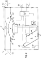
- FIG. 2 shows one of the devices 1 schematically in more detail.
- a duct 2 for letting water passing through the device 1 from an inlet connector 3 of the duct or device, respectively, to an outlet connector 4 of the duct or device is shown.
- the connectors for connecting the device 1 and thus the duct 2 to the water conduit 20 are just depicted schematically and with reference numerals 3 and 4. This can be standard water line connectors. Water will thus enter from conduit 20 under the pressure present in this conduit in direction W through connector 3 into duct 2 and the water will leave the duct into conduit 20 by connector 4. From the duct 2 a water line 6 connected to the duct 2 at an opening 16 thereof and leads to a valve arrangement 5 that is schematically shown only by a box.
- valve arrangement 5 Dotted lines show different water flow directions provided by the valve arrangement 5 and will be explained in the following. From the valve arrangement 5 another water line 7 leads back to the duct 2 and is connected there to the duct 2 at an opening 17. A third water line 8 leads from the valve arrangement 5 to a reservoir 9.
- the valve arrangement 5 is controlled by a control circuit of the device 1 which will be called controller 25.
- controller 25 This can be a control circuit based on a micro-computer well known to the skilled person.
- the controller 25 as well as the other components of device 1 which need electrical supply energy are supplied by electrical lines 22 already mentioned. If outside control signals are to be processed which enter via control lines 22' this will be done by controller 25 as well.
- the controller may thus receive signals from sensor 35 or may receive such sensors wirelessly as mentioned above.
- the controller 25 is connected to a wireless receiver of device 1 not shown in this embodiment.
- the controller controls as well the activation and deactivation of the droplet generator 10 which includes mesh 11 that provides the droplet outlet 12 of the device 1.
- the mesh 11 forms a part of the reservoir 9 such that water contained in the reservoir will be nebulized and will leave the device 1 at the outlet side 12 of the mesh.
- Reservoir 9 is filled by controlling valve arrangement 5 via controller 25 such that the valve arrangement 5 connects water line 6 with water line 8 while the valve arrangement blocks water line 7.
- Water from duct 2 supplied from conduit 20 is thus filled into reservoir 9.
- line 8 leads into reservoir 9 near the mesh 11 so that the mesh surface is flushed by water entering the reservoir via line 8.
- Filling is only allowed up to an upper fill-level F which is shown with a dotted line in the drawing.
- at least one fill sensor is provided that may preferably comprise a lower electrode and an upper electrode such that reaching the upper fill-level can be detected by a resistance measurement. When water is present between lower and upper fill-level electrodes the resistance measurement will give a lower value than without water connecting the electrodes.
- the lower electrode is provided by the mesh 11 itself which is at least partly electrically conductive so that it may serve as a fill-level electrode.
- the upper electrode 15 is a metal part within reservoir 9. Both electrodes 11, 15 are connected to controller 25 which effects the resistance measurement and can thus detect when the maximum fill-level has been reached.
- An intermediary electrode 18 may be provided as well. This electrode 18 is as well used by controller 25 to measure resistance between lower electrode 11 and electrode 18.
- controller 25 When the water has reached the maximum fill-level F in reservoir 9 controller 25 will control valve arrangement 5 to disconnect water line 8 from water line 6 and thus no further water will enter the reservoir. Controller 25 will then activate the droplet generator 10 which will vibrate mesh 11 so that a mist of water will leave device 1 at outlet 12. Thus the air in the respective compartment will be provided with extremely fine water droplets that will evaporate in the air of the compartment. Thus the compartment will be humidified and cooled. After the water in the reservoir 9 has been used up completely the step of filling the reservoir may be repeated if controller 25 still receives a message by sensor 35 that the controller interprets as a signal that even more humidification is needed. The filled up reservoir will then be emptied by nebulizing its content as well.
- reservoir 9 When the reservoir has been emptied and there is no need for further humidification, the reservoir will be left empty of water until a new request for humidification is recognised by controller 25. In this case the reservoir will be filled and nebulizing will start again. It is a preferred mode of operation of the device 1 that reservoir 9 is kept empty when no actual humidification is needed. In this way there is no or almost no residual water in the reservoir 9 and thus there are no concerns over the hygienic properties of the water.
- the controller 25 controls valve arrangement 5 such that water line 6 - which is no longer connected to water line 8 and the reservoir, respectively - is then connected to water line 7 so that water entering water line 6, the valve arrangement 5 and then water line 7 exits the device via duct 2 and flows to conduit 20 connected to outflow connector 4.
- the lines 6 and 7 and the valve arrangement are cleaned all the time - except when the reservoir 9 is filled - with fresh water from the conduit 20 entering at inflow connector 3. This as well removes any concerns about residual water standing in lines 6 and 7 and in the valve arrangement.
- a main controller not shown may trigger a filling of reservoir 9 and nebulization as well for example over signal lines 22' connected to each device. This may be the case if the whole system with all devices 1 shall be activated for a functional control.
- Reservoir 9 is preferably provided with a pressure equalization opening 19 that is provided at the reservoir away from the mesh 11 and above the maximum fill-level. This opening 19 will protect the mesh 11 from overpressure during filling and will avoid at any time that water pressure in the reservoir becomes too high.
- the opening 19 may be closed by an air-permeable particle-tight closure, in particular a hydrophobic membrane to avoid any contamination of the reservoir.
- the duct 2 preferably comprises a throttle 23 to make sure that there will always be a flow through lines 6, 7 and the valve arrangement when and while this valve arrangement connects lines 6 and 7 bypassing the duct 2.
- the throttle can be formed by any throttling means known to the skilled person, for example by a section of said duct 2 with a lesser diameter.
- Reservoir 9 is shaped such that all the water contained therein will be nebulized. Depending on the mounting of the device on a wall or on a ceiling of the compartment the reservoir may have a different shape so make sure that the reservoir can be emptied totally. There are then two kind of devices that must be selected by the installing person depending on the mounting. It is possible and is preferred to shape the reservoir such that the mesh will be on the lowest level regardless of the wall or ceiling mounting position. Such a reservoir is preferred and schematically shown in Figure 2 . It is as well possible to provide the reservoir 9 with two meshes in different places, so that a different mesh is in operation depending on the mounting position of the device.
- a humidification device wherein water is nebulized by a vibrating mesh with very small holes.
- the mesh is part of a reservoir which is fed by a valve arrangement which allows to direct water from a conduit over several water lines within the device either back to the conduit or into the reservoir.
- the device and a system with such devices allow to humidify and/or cool compartments such as rooms with a very fine mist of water which is hardly visually detectable.
- the system and device is adapted to be part of a permanent installation with low maintenance.
Landscapes
- Chemical & Material Sciences (AREA)
- Engineering & Computer Science (AREA)
- General Engineering & Computer Science (AREA)
- Combustion & Propulsion (AREA)
- Mechanical Engineering (AREA)
- Physics & Mathematics (AREA)
- Dispersion Chemistry (AREA)
- Chemical Kinetics & Catalysis (AREA)
- Thermal Sciences (AREA)
- Organic Chemistry (AREA)
- Electromagnetism (AREA)
- Power Engineering (AREA)
- Fluid Mechanics (AREA)
- General Physics & Mathematics (AREA)
- Air Humidification (AREA)
Priority Applications (9)
| Application Number | Priority Date | Filing Date | Title |
|---|---|---|---|
| EP14003395.2A EP3002524B1 (en) | 2014-10-01 | 2014-10-01 | Device for producing water droplets for air humidification and a humidification system with such devices |
| US15/506,148 US10508820B2 (en) | 2014-10-01 | 2015-09-28 | Device for producing water droplets for air humidification and a humidification system with such devices |
| JP2017517720A JP6649374B2 (ja) | 2014-10-01 | 2015-09-28 | 空気加湿のための水滴を生成する装置およびこの種の装置を有する加湿システム |
| RU2017114970A RU2688297C2 (ru) | 2014-10-01 | 2015-09-28 | Устройство для получения капель воды для увлажнения воздуха и система увлажнения с такими устройствами |
| CN201580051011.5A CN107076442A (zh) | 2014-10-01 | 2015-09-28 | 产生用于空气加湿的微水滴的装置和具有所述装置的加湿系统 |
| PCT/CH2015/000143 WO2016049785A1 (en) | 2014-10-01 | 2015-09-28 | Device for producing water droplets for air humidification and a humidification system with such devices |
| KR1020177008633A KR102165109B1 (ko) | 2014-10-01 | 2015-09-28 | 공기 가습을 위한 수적 생성 장치 및 이런 장치를 갖는 가습 시스템 |
| CA2963317A CA2963317C (en) | 2014-10-01 | 2015-09-28 | Device for producing water droplets for air humidification and a humidification system with such devices |
| CN202310581832.6A CN116592443A (zh) | 2014-10-01 | 2015-09-28 | 用于产生微水滴的装置及其操作方法和具有所述装置的系统 |
Applications Claiming Priority (1)
| Application Number | Priority Date | Filing Date | Title |
|---|---|---|---|
| EP14003395.2A EP3002524B1 (en) | 2014-10-01 | 2014-10-01 | Device for producing water droplets for air humidification and a humidification system with such devices |
Publications (2)
| Publication Number | Publication Date |
|---|---|
| EP3002524A1 EP3002524A1 (en) | 2016-04-06 |
| EP3002524B1 true EP3002524B1 (en) | 2020-02-26 |
Family
ID=51690181
Family Applications (1)
| Application Number | Title | Priority Date | Filing Date |
|---|---|---|---|
| EP14003395.2A Active EP3002524B1 (en) | 2014-10-01 | 2014-10-01 | Device for producing water droplets for air humidification and a humidification system with such devices |
Country Status (8)
| Country | Link |
|---|---|
| US (1) | US10508820B2 (no) |
| EP (1) | EP3002524B1 (no) |
| JP (1) | JP6649374B2 (no) |
| KR (1) | KR102165109B1 (no) |
| CN (2) | CN116592443A (no) |
| CA (1) | CA2963317C (no) |
| RU (1) | RU2688297C2 (no) |
| WO (1) | WO2016049785A1 (no) |
Families Citing this family (4)
| Publication number | Priority date | Publication date | Assignee | Title |
|---|---|---|---|---|
| US10900680B2 (en) * | 2013-07-19 | 2021-01-26 | Ademco Inc. | Humidifier system |
| US9822990B2 (en) * | 2013-07-19 | 2017-11-21 | Honeywell International Inc. | Methods, systems, and devices for humidifying |
| CN112325409B (zh) * | 2020-11-04 | 2021-12-14 | 深圳众易达装饰有限公司 | 一种车间空气处理用智能式增湿器 |
| CN114060990B (zh) * | 2021-11-08 | 2022-12-13 | 佛山市南海科日超声电子有限公司 | 一种微孔加湿模块的集成工作液腔 |
Family Cites Families (25)
| Publication number | Priority date | Publication date | Assignee | Title |
|---|---|---|---|---|
| JPS54181752U (no) * | 1978-06-13 | 1979-12-22 | ||
| JPH09135877A (ja) | 1995-11-14 | 1997-05-27 | Toshio Shimizu | 洗浄器 |
| CN1178755C (zh) | 2000-10-05 | 2004-12-08 | 欧姆龙株式会社 | 液体喷雾装置 |
| US6511050B2 (en) * | 2001-05-02 | 2003-01-28 | Dynamo Aviation, Inc. | Humidifier |
| US6915962B2 (en) * | 2002-05-20 | 2005-07-12 | Aerogen, Inc. | Apparatus for providing aerosol for medical treatment and methods |
| CN2593097Y (zh) * | 2002-12-10 | 2003-12-17 | 陈小榴 | 一种超声波空气加湿器 |
| JP2006292249A (ja) * | 2005-04-08 | 2006-10-26 | Matsushita Electric Ind Co Ltd | 加湿ユニットの給排水装置 |
| JP2008023026A (ja) | 2006-07-20 | 2008-02-07 | Alfresa Pharma Corp | 噴霧機及び噴霧機の洗浄方法 |
| KR100870903B1 (ko) * | 2007-02-13 | 2008-11-28 | 김덕용 | 빌트인 가습기 |
| JP5290561B2 (ja) * | 2007-10-22 | 2013-09-18 | ホーチキ株式会社 | 噴霧冷房設備及び噴霧方法 |
| GB2458162A (en) * | 2008-03-07 | 2009-09-09 | Reckitt Benckiser | Air cleaner |
| JP2010007897A (ja) * | 2008-06-25 | 2010-01-14 | Sanyo Electric Co Ltd | 噴霧装置の貯液タンク |
| WO2010015124A1 (en) * | 2008-08-06 | 2010-02-11 | Electrolux (Hangzhou) Home Appliances Co., Ltd. | Humidifying air-conditioner |
| ES2642585T3 (es) | 2009-04-23 | 2017-11-16 | Fraunhofer-Gesellschaft zur Förderung der angewandten Forschung e.V. | Aparato mejorado de aerosolización de grandes volúmenes de polvo seco |
| KR20110036974A (ko) * | 2009-10-05 | 2011-04-13 | 수경 이 | 초음파 증기 가습기 |
| JP2011094846A (ja) * | 2009-10-28 | 2011-05-12 | Sanyo Electric Co Ltd | 噴霧装置 |
| JP2012093032A (ja) * | 2010-10-27 | 2012-05-17 | Sanyo Electric Co Ltd | ミスト生成器 |
| CN103402907B (zh) * | 2011-01-17 | 2016-03-23 | 新加坡科技研究局 | 微流体微滴发生器 |
| CN102954549A (zh) * | 2011-08-24 | 2013-03-06 | 希姆通信息技术(上海)有限公司 | 具有加湿功能的移动终端 |
| KR101102006B1 (ko) * | 2011-09-09 | 2012-01-04 | 주식회사 에스티 | 천장매립형 기화식 가습기의 가습용수 제어시스템 |
| CN202532646U (zh) * | 2012-03-17 | 2012-11-14 | 广州市番禺奥迪威电子有限公司 | 一种感应加湿器 |
| KR200474118Y1 (ko) * | 2012-10-29 | 2014-08-25 | 주식회사 에스티 | 기화식 가습기용 물받이의 가습용수 제어장치 |
| KR101466768B1 (ko) | 2013-02-27 | 2014-11-28 | 케이티메드 주식회사 | 약액흡입기용 약액용기 및 약액흡입기 |
| CN203249363U (zh) * | 2013-05-07 | 2013-10-23 | 方春风 | 一种用于室内空气自动调控湿度的设备 |
| JP5991360B2 (ja) * | 2014-09-30 | 2016-09-14 | ダイキン工業株式会社 | 水処理装置及び加湿装置 |
-
2014
- 2014-10-01 EP EP14003395.2A patent/EP3002524B1/en active Active
-
2015
- 2015-09-28 CA CA2963317A patent/CA2963317C/en active Active
- 2015-09-28 US US15/506,148 patent/US10508820B2/en active Active
- 2015-09-28 WO PCT/CH2015/000143 patent/WO2016049785A1/en active Application Filing
- 2015-09-28 CN CN202310581832.6A patent/CN116592443A/zh active Pending
- 2015-09-28 JP JP2017517720A patent/JP6649374B2/ja active Active
- 2015-09-28 CN CN201580051011.5A patent/CN107076442A/zh active Pending
- 2015-09-28 RU RU2017114970A patent/RU2688297C2/ru active
- 2015-09-28 KR KR1020177008633A patent/KR102165109B1/ko active IP Right Grant
Non-Patent Citations (1)
| Title |
|---|
| None * |
Also Published As
| Publication number | Publication date |
|---|---|
| JP2017534041A (ja) | 2017-11-16 |
| CN107076442A (zh) | 2017-08-18 |
| US10508820B2 (en) | 2019-12-17 |
| WO2016049785A1 (en) | 2016-04-07 |
| KR20170062463A (ko) | 2017-06-07 |
| CA2963317A1 (en) | 2016-04-07 |
| US20170276387A1 (en) | 2017-09-28 |
| KR102165109B1 (ko) | 2020-10-14 |
| CA2963317C (en) | 2022-06-21 |
| RU2017114970A3 (no) | 2019-01-18 |
| EP3002524A1 (en) | 2016-04-06 |
| RU2688297C2 (ru) | 2019-05-21 |
| RU2017114970A (ru) | 2018-11-06 |
| JP6649374B2 (ja) | 2020-02-19 |
| CN116592443A (zh) | 2023-08-15 |
Similar Documents
| Publication | Publication Date | Title |
|---|---|---|
| US10508820B2 (en) | Device for producing water droplets for air humidification and a humidification system with such devices | |
| CN106871308B (zh) | 利用垂直型电力传输方式的悬浮式加湿器 | |
| AU2016335360B2 (en) | Smoke detector tester | |
| JP6584644B2 (ja) | 超粒子噴霧装置 | |
| JP2014057952A (ja) | 霧発生装置 | |
| US20080011873A1 (en) | Optimized method of atomizing liquid and a liquid atomizer device for implementing the method | |
| JP2017534041A5 (no) | ||
| KR101703882B1 (ko) | 새집증후군 방지용 약제 연무분사시스템 | |
| JP5616828B2 (ja) | 加煙試験器 | |
| US10492461B2 (en) | Cage system comprising a climate control unit having a low flow vaporizer | |
| CN113085929B (zh) | 列车卫生间空调器的杀菌控制方法及列车卫生间空调器 | |
| JP2020062299A (ja) | アロマディフューザー | |
| JP7397257B2 (ja) | 超音波式噴霧器 | |
| JP2011174677A (ja) | ミスト生成器 | |
| KR20110010469U (ko) | 교체박스가 구비된 가습기 | |
| KR200322883Y1 (ko) | 분리형 산소발생장치 | |
| WO2005034831A1 (ja) | サウナ用蒸気発生装置 | |
| JP2021156482A (ja) | 加湿装置 | |
| WO2020162779A1 (ru) | Персональное устройство климат-контроля в помещении | |
| JP2005152771A (ja) | 塗装ブース用処理水の自動給水方法 | |
| JP2016034609A (ja) | 霧化溶剤吐出装置 | |
| JP2011085338A (ja) | 霧発生装置 |
Legal Events
| Date | Code | Title | Description |
|---|---|---|---|
| PUAI | Public reference made under article 153(3) epc to a published international application that has entered the european phase |
Free format text: ORIGINAL CODE: 0009012 |
|
| AK | Designated contracting states |
Kind code of ref document: A1 Designated state(s): AL AT BE BG CH CY CZ DE DK EE ES FI FR GB GR HR HU IE IS IT LI LT LU LV MC MK MT NL NO PL PT RO RS SE SI SK SM TR |
|
| AX | Request for extension of the european patent |
Extension state: BA ME |
|
| RAP1 | Party data changed (applicant data changed or rights of an application transferred) |
Owner name: CONDAIR GROUP AG |
|
| 17P | Request for examination filed |
Effective date: 20160921 |
|
| RBV | Designated contracting states (corrected) |
Designated state(s): AL AT BE BG CH CY CZ DE DK EE ES FI FR GB GR HR HU IE IS IT LI LT LU LV MC MK MT NL NO PL PT RO RS SE SI SK SM TR |
|
| GRAP | Despatch of communication of intention to grant a patent |
Free format text: ORIGINAL CODE: EPIDOSNIGR1 |
|
| STAA | Information on the status of an ep patent application or granted ep patent |
Free format text: STATUS: GRANT OF PATENT IS INTENDED |
|
| INTG | Intention to grant announced |
Effective date: 20191029 |
|
| GRAS | Grant fee paid |
Free format text: ORIGINAL CODE: EPIDOSNIGR3 |
|
| GRAA | (expected) grant |
Free format text: ORIGINAL CODE: 0009210 |
|
| STAA | Information on the status of an ep patent application or granted ep patent |
Free format text: STATUS: THE PATENT HAS BEEN GRANTED |
|
| AK | Designated contracting states |
Kind code of ref document: B1 Designated state(s): AL AT BE BG CH CY CZ DE DK EE ES FI FR GB GR HR HU IE IS IT LI LT LU LV MC MK MT NL NO PL PT RO RS SE SI SK SM TR |
|
| RAP1 | Party data changed (applicant data changed or rights of an application transferred) |
Owner name: CONDAIR GROUP AG |
|
| REG | Reference to a national code |
Ref country code: GB Ref legal event code: FG4D |
|
| REG | Reference to a national code |
Ref country code: CH Ref legal event code: NV Representative=s name: E. BLUM AND CO. AG PATENT- UND MARKENANWAELTE , CH Ref country code: CH Ref legal event code: EP |
|
| REG | Reference to a national code |
Ref country code: DE Ref legal event code: R082 Ref document number: 602014061411 Country of ref document: DE |
|
| REG | Reference to a national code |
Ref country code: AT Ref legal event code: REF Ref document number: 1238102 Country of ref document: AT Kind code of ref document: T Effective date: 20200315 |
|
| REG | Reference to a national code |
Ref country code: IE Ref legal event code: FG4D |
|
| REG | Reference to a national code |
Ref country code: DE Ref legal event code: R096 Ref document number: 602014061411 Country of ref document: DE |
|
| REG | Reference to a national code |
Ref country code: SE Ref legal event code: TRGR |
|
| REG | Reference to a national code |
Ref country code: NL Ref legal event code: FP |
|
| PG25 | Lapsed in a contracting state [announced via postgrant information from national office to epo] |
Ref country code: FI Free format text: LAPSE BECAUSE OF FAILURE TO SUBMIT A TRANSLATION OF THE DESCRIPTION OR TO PAY THE FEE WITHIN THE PRESCRIBED TIME-LIMIT Effective date: 20200226 Ref country code: RS Free format text: LAPSE BECAUSE OF FAILURE TO SUBMIT A TRANSLATION OF THE DESCRIPTION OR TO PAY THE FEE WITHIN THE PRESCRIBED TIME-LIMIT Effective date: 20200226 Ref country code: NO Free format text: LAPSE BECAUSE OF FAILURE TO SUBMIT A TRANSLATION OF THE DESCRIPTION OR TO PAY THE FEE WITHIN THE PRESCRIBED TIME-LIMIT Effective date: 20200526 |
|
| REG | Reference to a national code |
Ref country code: LT Ref legal event code: MG4D |
|
| PG25 | Lapsed in a contracting state [announced via postgrant information from national office to epo] |
Ref country code: BG Free format text: LAPSE BECAUSE OF FAILURE TO SUBMIT A TRANSLATION OF THE DESCRIPTION OR TO PAY THE FEE WITHIN THE PRESCRIBED TIME-LIMIT Effective date: 20200526 Ref country code: IS Free format text: LAPSE BECAUSE OF FAILURE TO SUBMIT A TRANSLATION OF THE DESCRIPTION OR TO PAY THE FEE WITHIN THE PRESCRIBED TIME-LIMIT Effective date: 20200626 Ref country code: LV Free format text: LAPSE BECAUSE OF FAILURE TO SUBMIT A TRANSLATION OF THE DESCRIPTION OR TO PAY THE FEE WITHIN THE PRESCRIBED TIME-LIMIT Effective date: 20200226 Ref country code: GR Free format text: LAPSE BECAUSE OF FAILURE TO SUBMIT A TRANSLATION OF THE DESCRIPTION OR TO PAY THE FEE WITHIN THE PRESCRIBED TIME-LIMIT Effective date: 20200527 Ref country code: HR Free format text: LAPSE BECAUSE OF FAILURE TO SUBMIT A TRANSLATION OF THE DESCRIPTION OR TO PAY THE FEE WITHIN THE PRESCRIBED TIME-LIMIT Effective date: 20200226 |
|
| PG25 | Lapsed in a contracting state [announced via postgrant information from national office to epo] |
Ref country code: SK Free format text: LAPSE BECAUSE OF FAILURE TO SUBMIT A TRANSLATION OF THE DESCRIPTION OR TO PAY THE FEE WITHIN THE PRESCRIBED TIME-LIMIT Effective date: 20200226 Ref country code: PT Free format text: LAPSE BECAUSE OF FAILURE TO SUBMIT A TRANSLATION OF THE DESCRIPTION OR TO PAY THE FEE WITHIN THE PRESCRIBED TIME-LIMIT Effective date: 20200719 Ref country code: DK Free format text: LAPSE BECAUSE OF FAILURE TO SUBMIT A TRANSLATION OF THE DESCRIPTION OR TO PAY THE FEE WITHIN THE PRESCRIBED TIME-LIMIT Effective date: 20200226 Ref country code: SM Free format text: LAPSE BECAUSE OF FAILURE TO SUBMIT A TRANSLATION OF THE DESCRIPTION OR TO PAY THE FEE WITHIN THE PRESCRIBED TIME-LIMIT Effective date: 20200226 Ref country code: LT Free format text: LAPSE BECAUSE OF FAILURE TO SUBMIT A TRANSLATION OF THE DESCRIPTION OR TO PAY THE FEE WITHIN THE PRESCRIBED TIME-LIMIT Effective date: 20200226 Ref country code: EE Free format text: LAPSE BECAUSE OF FAILURE TO SUBMIT A TRANSLATION OF THE DESCRIPTION OR TO PAY THE FEE WITHIN THE PRESCRIBED TIME-LIMIT Effective date: 20200226 Ref country code: RO Free format text: LAPSE BECAUSE OF FAILURE TO SUBMIT A TRANSLATION OF THE DESCRIPTION OR TO PAY THE FEE WITHIN THE PRESCRIBED TIME-LIMIT Effective date: 20200226 Ref country code: ES Free format text: LAPSE BECAUSE OF FAILURE TO SUBMIT A TRANSLATION OF THE DESCRIPTION OR TO PAY THE FEE WITHIN THE PRESCRIBED TIME-LIMIT Effective date: 20200226 Ref country code: CZ Free format text: LAPSE BECAUSE OF FAILURE TO SUBMIT A TRANSLATION OF THE DESCRIPTION OR TO PAY THE FEE WITHIN THE PRESCRIBED TIME-LIMIT Effective date: 20200226 |
|
| REG | Reference to a national code |
Ref country code: AT Ref legal event code: MK05 Ref document number: 1238102 Country of ref document: AT Kind code of ref document: T Effective date: 20200226 |
|
| REG | Reference to a national code |
Ref country code: DE Ref legal event code: R097 Ref document number: 602014061411 Country of ref document: DE |
|
| PLBE | No opposition filed within time limit |
Free format text: ORIGINAL CODE: 0009261 |
|
| STAA | Information on the status of an ep patent application or granted ep patent |
Free format text: STATUS: NO OPPOSITION FILED WITHIN TIME LIMIT |
|
| PG25 | Lapsed in a contracting state [announced via postgrant information from national office to epo] |
Ref country code: IT Free format text: LAPSE BECAUSE OF FAILURE TO SUBMIT A TRANSLATION OF THE DESCRIPTION OR TO PAY THE FEE WITHIN THE PRESCRIBED TIME-LIMIT Effective date: 20200226 Ref country code: AT Free format text: LAPSE BECAUSE OF FAILURE TO SUBMIT A TRANSLATION OF THE DESCRIPTION OR TO PAY THE FEE WITHIN THE PRESCRIBED TIME-LIMIT Effective date: 20200226 |
|
| 26N | No opposition filed |
Effective date: 20201127 |
|
| PG25 | Lapsed in a contracting state [announced via postgrant information from national office to epo] |
Ref country code: SI Free format text: LAPSE BECAUSE OF FAILURE TO SUBMIT A TRANSLATION OF THE DESCRIPTION OR TO PAY THE FEE WITHIN THE PRESCRIBED TIME-LIMIT Effective date: 20200226 Ref country code: PL Free format text: LAPSE BECAUSE OF FAILURE TO SUBMIT A TRANSLATION OF THE DESCRIPTION OR TO PAY THE FEE WITHIN THE PRESCRIBED TIME-LIMIT Effective date: 20200226 |
|
| GBPC | Gb: european patent ceased through non-payment of renewal fee |
Effective date: 20201001 |
|
| PG25 | Lapsed in a contracting state [announced via postgrant information from national office to epo] |
Ref country code: MC Free format text: LAPSE BECAUSE OF FAILURE TO SUBMIT A TRANSLATION OF THE DESCRIPTION OR TO PAY THE FEE WITHIN THE PRESCRIBED TIME-LIMIT Effective date: 20200226 Ref country code: LU Free format text: LAPSE BECAUSE OF NON-PAYMENT OF DUE FEES Effective date: 20201001 |
|
| REG | Reference to a national code |
Ref country code: BE Ref legal event code: MM Effective date: 20201031 |
|
| PG25 | Lapsed in a contracting state [announced via postgrant information from national office to epo] |
Ref country code: FR Free format text: LAPSE BECAUSE OF NON-PAYMENT OF DUE FEES Effective date: 20201031 |
|
| PG25 | Lapsed in a contracting state [announced via postgrant information from national office to epo] |
Ref country code: GB Free format text: LAPSE BECAUSE OF NON-PAYMENT OF DUE FEES Effective date: 20201001 Ref country code: BE Free format text: LAPSE BECAUSE OF NON-PAYMENT OF DUE FEES Effective date: 20201031 |
|
| PG25 | Lapsed in a contracting state [announced via postgrant information from national office to epo] |
Ref country code: IE Free format text: LAPSE BECAUSE OF NON-PAYMENT OF DUE FEES Effective date: 20201001 |
|
| PG25 | Lapsed in a contracting state [announced via postgrant information from national office to epo] |
Ref country code: TR Free format text: LAPSE BECAUSE OF FAILURE TO SUBMIT A TRANSLATION OF THE DESCRIPTION OR TO PAY THE FEE WITHIN THE PRESCRIBED TIME-LIMIT Effective date: 20200226 Ref country code: MT Free format text: LAPSE BECAUSE OF FAILURE TO SUBMIT A TRANSLATION OF THE DESCRIPTION OR TO PAY THE FEE WITHIN THE PRESCRIBED TIME-LIMIT Effective date: 20200226 Ref country code: CY Free format text: LAPSE BECAUSE OF FAILURE TO SUBMIT A TRANSLATION OF THE DESCRIPTION OR TO PAY THE FEE WITHIN THE PRESCRIBED TIME-LIMIT Effective date: 20200226 |
|
| PG25 | Lapsed in a contracting state [announced via postgrant information from national office to epo] |
Ref country code: MK Free format text: LAPSE BECAUSE OF FAILURE TO SUBMIT A TRANSLATION OF THE DESCRIPTION OR TO PAY THE FEE WITHIN THE PRESCRIBED TIME-LIMIT Effective date: 20200226 Ref country code: AL Free format text: LAPSE BECAUSE OF FAILURE TO SUBMIT A TRANSLATION OF THE DESCRIPTION OR TO PAY THE FEE WITHIN THE PRESCRIBED TIME-LIMIT Effective date: 20200226 |
|
| P01 | Opt-out of the competence of the unified patent court (upc) registered |
Effective date: 20230427 |
|
| PGFP | Annual fee paid to national office [announced via postgrant information from national office to epo] |
Ref country code: NL Payment date: 20231019 Year of fee payment: 10 |
|
| PGFP | Annual fee paid to national office [announced via postgrant information from national office to epo] |
Ref country code: SE Payment date: 20231019 Year of fee payment: 10 Ref country code: DE Payment date: 20231020 Year of fee payment: 10 Ref country code: CH Payment date: 20231101 Year of fee payment: 10 |