EP3002456B1 - Wind power generator - Google Patents
Wind power generator Download PDFInfo
- Publication number
- EP3002456B1 EP3002456B1 EP15187527.5A EP15187527A EP3002456B1 EP 3002456 B1 EP3002456 B1 EP 3002456B1 EP 15187527 A EP15187527 A EP 15187527A EP 3002456 B1 EP3002456 B1 EP 3002456B1
- Authority
- EP
- European Patent Office
- Prior art keywords
- nacelle
- nacelle cover
- bent
- upside
- cover
- Prior art date
- Legal status (The legal status is an assumption and is not a legal conclusion. Google has not performed a legal analysis and makes no representation as to the accuracy of the status listed.)
- Not-in-force
Links
- 238000007789 sealing Methods 0.000 claims description 30
- 239000010687 lubricating oil Substances 0.000 description 14
- 230000007774 longterm Effects 0.000 description 8
- 230000000149 penetrating effect Effects 0.000 description 6
- 230000000694 effects Effects 0.000 description 5
- 230000001771 impaired effect Effects 0.000 description 5
- 238000012423 maintenance Methods 0.000 description 5
- 229910052710 silicon Inorganic materials 0.000 description 5
- 239000010703 silicon Substances 0.000 description 5
- 230000006866 deterioration Effects 0.000 description 4
- 239000000428 dust Substances 0.000 description 4
- 230000035515 penetration Effects 0.000 description 3
- 230000007423 decrease Effects 0.000 description 2
- 238000010248 power generation Methods 0.000 description 2
- 230000005540 biological transmission Effects 0.000 description 1
Images


Classifications
-
- F—MECHANICAL ENGINEERING; LIGHTING; HEATING; WEAPONS; BLASTING
- F03—MACHINES OR ENGINES FOR LIQUIDS; WIND, SPRING, OR WEIGHT MOTORS; PRODUCING MECHANICAL POWER OR A REACTIVE PROPULSIVE THRUST, NOT OTHERWISE PROVIDED FOR
- F03D—WIND MOTORS
- F03D80/00—Details, components or accessories not provided for in groups F03D1/00 - F03D17/00
- F03D80/80—Arrangement of components within nacelles or towers
- F03D80/88—Arrangement of components within nacelles or towers of mechanical components
-
- F—MECHANICAL ENGINEERING; LIGHTING; HEATING; WEAPONS; BLASTING
- F05—INDEXING SCHEMES RELATING TO ENGINES OR PUMPS IN VARIOUS SUBCLASSES OF CLASSES F01-F04
- F05B—INDEXING SCHEME RELATING TO WIND, SPRING, WEIGHT, INERTIA OR LIKE MOTORS, TO MACHINES OR ENGINES FOR LIQUIDS COVERED BY SUBCLASSES F03B, F03D AND F03G
- F05B2240/00—Components
- F05B2240/10—Stators
- F05B2240/14—Casings, housings, nacelles, gondels or the like, protecting or supporting assemblies there within
-
- F—MECHANICAL ENGINEERING; LIGHTING; HEATING; WEAPONS; BLASTING
- F05—INDEXING SCHEMES RELATING TO ENGINES OR PUMPS IN VARIOUS SUBCLASSES OF CLASSES F01-F04
- F05B—INDEXING SCHEME RELATING TO WIND, SPRING, WEIGHT, INERTIA OR LIKE MOTORS, TO MACHINES OR ENGINES FOR LIQUIDS COVERED BY SUBCLASSES F03B, F03D AND F03G
- F05B2240/00—Components
- F05B2240/40—Use of a multiplicity of similar components
-
- Y—GENERAL TAGGING OF NEW TECHNOLOGICAL DEVELOPMENTS; GENERAL TAGGING OF CROSS-SECTIONAL TECHNOLOGIES SPANNING OVER SEVERAL SECTIONS OF THE IPC; TECHNICAL SUBJECTS COVERED BY FORMER USPC CROSS-REFERENCE ART COLLECTIONS [XRACs] AND DIGESTS
- Y02—TECHNOLOGIES OR APPLICATIONS FOR MITIGATION OR ADAPTATION AGAINST CLIMATE CHANGE
- Y02B—CLIMATE CHANGE MITIGATION TECHNOLOGIES RELATED TO BUILDINGS, e.g. HOUSING, HOUSE APPLIANCES OR RELATED END-USER APPLICATIONS
- Y02B10/00—Integration of renewable energy sources in buildings
- Y02B10/30—Wind power
-
- Y—GENERAL TAGGING OF NEW TECHNOLOGICAL DEVELOPMENTS; GENERAL TAGGING OF CROSS-SECTIONAL TECHNOLOGIES SPANNING OVER SEVERAL SECTIONS OF THE IPC; TECHNICAL SUBJECTS COVERED BY FORMER USPC CROSS-REFERENCE ART COLLECTIONS [XRACs] AND DIGESTS
- Y02—TECHNOLOGIES OR APPLICATIONS FOR MITIGATION OR ADAPTATION AGAINST CLIMATE CHANGE
- Y02E—REDUCTION OF GREENHOUSE GAS [GHG] EMISSIONS, RELATED TO ENERGY GENERATION, TRANSMISSION OR DISTRIBUTION
- Y02E10/00—Energy generation through renewable energy sources
- Y02E10/70—Wind energy
- Y02E10/72—Wind turbines with rotation axis in wind direction
Definitions
- the present invention relates to a wind power generator, especially to a suitable wind power generator provided with a nacelle which is configured by plural panels and the crust of which is formed by a nacelle cover having dividable structure.
- the wind power generator transmits the rotational power of a hub that supports blades to a generator, rotates a rotor of the generator, generates power
- the hub is configured by the generator, a gearbox, a controller, electric equipment and others, and the hub is attached to an end of a nacelle.
- the output of the wind power generator has been recently increased and the size of equipment that configures the wind power generator is becoming larger.
- the nacelle is also becoming larger and a nacelle cover that forms a crust of the nacelle is configured by plural panels.
- nacelle cover a function for preventing rainwater, dust and others from penetrating inside the nacelle is demanded, and the maintenance of equipment such as the generator, the gearbox housed in the nacelle and the facility of disassembly in the carriage in/out of them are also demanded.
- a nacelle cover configured by plural panels in a conventional type wind power generator is disclosed in International Publication Nos. WO 2012/060370 and WO 2012/077618 .
- International Publication No. WO 2012/060370 structure is disclosed in which a sealing member is provided substantially in parallel with a joint in the joint of plural upside nacelle covers.
- International Publication No. WO 2012/077618 structure that an upside nacelle cover covers a joint in the joint of plural side nacelle covers is disclosed.
- a bolt utilized for junction is arranged in a position in which it is directly exposed to the weather in the configuration described in International Publication No. WO 2012/077618 , the bolt may be corroded and a sealing member for closing a bolt hole may be easily deteriorated. Therefore, in long-term use, water-tightness may be impaired.
- WO 2012/060370 and WO 2012/077618 relate to the structure of a top face and a side of the nacelle cover.
- the water-tightness of a bottom is also an important subject.
- the bottom of the nacelle cover it is also an important subject to prevent lubricating oil from leaking out of the nacelle when the lubricating oil leaks out of equipment inside the nacelle.
- the present invention is made in view of the abovementioned matters and its object is to provide a wind power generator that prevents rainwater and dust from penetrating into a joint of nacelle covers regardless of a location and can maintain this effect for a long term.
- the wind power generator according to the present invention is based upon a wind power generator which is provided with a rotor configured by a hub and blades, a generator connected to the rotor via a main shaft connected to the hub, a nacelle that houses at least the generator and journals the rotor via the main shaft and a tower that supports the nacelle at the top so as to achieve the object and in which the nacelle is configured by plural panels and its crust is formed by a nacelle cover having dividable structure, and has a characteristic that bent parts are provided in a joint of ends of the plural nacelle covers and a communicating part with the outside, an inside communicating part communicating with the inside of the nacelle and an intermediate communicating part that makes the inside communicating part and the communicating part with the outside communicate are formed between the bent parts in the joint of the ends of the adjacent nacelle covers.
- the wind power generator according to the present invention is based upon a wind power generator which is provided with a rotor configured by a hub and blades, a generator connected to the rotor via a main shaft connected to the hub, a nacelle that houses at least the generator and journals the rotor via the main shaft and a tower that supports the nacelle at the top and in which the nacelle is configured by plural panels and its crust is formed by a nacelle cover having dividable structure so as to achieve the object, and has a characteristic that a top face, a side and a bottom of the nacelle are respectively configured by plural panels, its crust is formed by the nacelle cover having dividable structure, bent parts are provided in a joint of ends of respective plural nacelle covers to be the top face, the side and the bottom of the nacelle and a communicating part with the outside, an inside communicating part communicating with the inside of the nacelle and an intermediate communicating part that makes the inside communicating part and the communicating part with the outside communicate are formed between the bent parts in the
- a wind power generator according to the present invention will be described on the basis of embodiments shown in the drawings below.
- the same reference numeral is used for the same component.
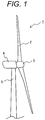
- Fig. 1 shows the whole configuration of the wind power generator
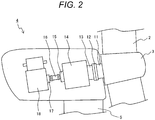
- Fig. 2 shows schematic structure of the inside of a nacelle including the generator and a gearbox inside.
- the wind power generator 1 is schematically configured by a blade 2 that catches wind, a hub 3 that supports the blade 2, the nacelle 4 that supports the hub 3 and a tower 5 that supports the nacelle 4, and a rotor is configured by the hub 3 and the blade 2.
- the blade 2 has a rotational degree of freedom in a substantially longitudinal direction of the blade 2
- the hub 3 has it in its substantially horizontal direction
- the nacelle 4 has a rotational degree of freedom in its substantially vertical direction.
- a gearbox 14, a generator 18 and others are included inside the nacelle 4, inside the nacelle 4, a gearbox 14, a generator 18 and others are included.
- a hub rotating shaft 11 connected to the hub 3 and an input shaft 13 to the gearbox 14 are connected via a joint 12
- an output shaft 15 from the gearbox 14 and an input shaft 17 to the generator 18 are connected via a joint 16
- a main shaft 17 is configured by the hub rotating shaft 11, the input shaft 13 to the gearbox, the output shaft 15 from the gearbox and the input shaft 17 to the generator.
- Fig. 3 shows a state in which plural pieces of a nacelle cover are assembled to be the nacelle 4 which is configured by plural panels and a crust of which is formed by the nacelle cover having dividable structure.
- the nacelle cover is configured by upside nacelle covers 21a, 21b, 21c, 21d, side nacelle covers 41a, 41b, 41c, 41d, bottom nacelle covers 61a, 61b, 61c, 61d and others, and is configured so that the nacelle cover can be divided into plural panels.
- the upside nacelle covers 21a, 21b, 21c, 21d and the bottom nacelle covers 61a, 61b 61c, 61d are continuously arranged in an axial direction of the main shaft and as to the side nacelle covers 41a, 41b, 41c, 41d, the side nacelle covers 41a, 41b and the side nacelle covers 41c, 41d respectively continuously arranged in the axial direction of the main shaft are arranged with them piled in a vertical direction of the nacelle 4 (on the opposite side of the side nacelle covers 41a, 41b, 41c, 41d, side nacelle covers 41e, 41f, 41g, 41h are similarly arranged though they are not especially shown).
- the nacelle cover has structure that enables inside approach by removing a part of the nacelle covers (see Figs. 7 and 10 ) though the parts are described later in the maintenance and the attachment/detachment of the equipment inside the nacelle 4.
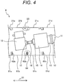
- Fig. 4 shows a section viewed along a broken line 81 shown in Fig. 3 in the wind power generator in the first embodiment of the present invention
- Fig. 5 is an enlarged view showing an area 83 encircled by a circle shown by a broken line in Fig. 4 .
- the upside nacelle covers 21a, 21b, 21c, 21d are divided substantially in a direction shown by an arrow 91 (in the axial direction of the main shaft).
- An end of the upside nacelle cover 21a covers an end of the adjacent upside nacelle cover 21b from its upside (it can also be said that the end of the upside nacelle cover 21b enters the downside of the end of the adjacent upside nacelle cover 21a), the other end of the upside nacelle cover 21b covers an end of the adjacent upside nacelle cover 21c from its upside, and a joint of the end of the upside nacelle cover 21c and an end of the upside nacelle cover 21d also has a similar configuration.
- the end of the upside nacelle cover 21b and the end of the upside nacelle cover 21c are respectively provided with a bent part (a joint of the other upside nacelle covers also has similar structure), and a communicating part 22 with the outside, an inside communicating part 24 communicating with the inside of the nacelle 4 and an intermediate communicating part 23 that makes the inside communicating part 24 and the communicating part 22 with the outside communicate are configured by combining these bent parts.
- the end 21b1 of the adjacent upside nacelle cover 21b is bent and extended inside in an L type
- the end 21c1 of the adjacent upside nacelle cover 21c is bent and extended inside in parallel with the L-type end 21b1 of the upside nacelle cover 21b via predetermined clearance
- the communicating part 22 with the outside is formed between bent parts of the ends 21b1 and 21c1 respectively bent and extended inside of the upside nacelle covers 21b and 21c.
- the edge (to be a part shown by a reference numeral 21c2) bent and extended in an L type of the end 21c1 of the upside nacelle cover 21c is bent and extended to be parallel with a part except the end 21b1 of the upside nacelle cover 21b (an outer surface of the upside nacelle cover 21b), an extended edge (to be a part shown by as reference numeral 21c3) of the bent part 21c2 is bent and extended outside to be parallel with the L-type ends 21b1, 21c1 of the upside nacelle covers 21b, 21c, and the intermediate communicating part 23 that makes the inside communicating part 24 and the communicating part 22 with the outside communicate is formed in a part encircled by the part 21c3 bent and extended outside, the part 21c2 bent and extended to be parallel with the part except the end (21b1) of the upside nacelle cover 21b, the upside nacelle cover 21b and one end 21b1 bent and extended in the L type of the upside nacelle cover.
- an edge (to be a part shown by a reference numeral 21c4) of the part (the part shown by the reference numeral 21c3) bent and extended outside of the upside nacelle cover 21c is bent and extended to be parallel with the part (the part shown by the reference numeral 21b) except the end of the upside nacelle cover 21b, the inside communicating part 24 communicating with the inside of the nacelle 4 is formed between the bent and extended part (21c4) and the upside nacelle cover 21b, and a sealing member 25 made of silicon or fluororesin is arranged in the inside communicating part 24.
- the upside nacelle cover 21b and the upside nacelle cover 21c are fixed using a nut 26 fixed inside the upside nacelle cover 21b and a bolt 27, and the upside nacelle cover 21c is fixed to a frame 28 fixed to the tower 5 by a bolt 29. That is, the upside nacelle cover 21c is fixed to the frame 28 fixed to the tower 5, and the upside nacelle cover 21b and the upside nacelle cover 21c are fastened by inserting the bolt 27 into the nut 26 fixed inside the upside nacelle cover 21b.
- the nut 26 has such thickness that top faces of the upside nacelle cover 21b and the upside nacelle cover 21c are at the substantially same level and the sealing member 25 is appropriately compressed (thickness to the extent that the sealing member 25 is not damaged even if it is compressed).
- holes 30a, 30b with which the bolt 27 and the bolt 29 communicate and which are provided to the nacelle cover 21c are a hole longer in the direction shown by the arrow 91 (in the axial direction of the main shaft) and the clearance in the direction shown by the arrow 91 in the communicating part 22 with the outside can be adjusted by the holes.
- the sealing member 25 is basically not exposed to the weather, the deterioration hardly progresses and it can be expected that water-tightness is maintained for a long term. Furthermore, in the maintenance of the equipment inside the nacelle 4 and replacement work, the upside nacelle covers of a required number have only to be detached, and for example, when access to the generator 18 shown in Fig. 4 is frequent, a shape of the end of the upside nacelle cover has only to be determined so that the upside nacelle cover 21b close to a location in which the generator 18 is installed can be detached earliest as shown in Fig. 7 .
- the nut 26 used for fixing the upside nacelle cover 21b and the upside nacelle cover 21c is provided inside the upside nacelle cover 21b and the nut is not protruded from the outer surface of the nacelle 4, the nut does not disturb a flow of air around the nacelle 4 and does not impair its hydrodynamic performance. This is especially effective in a so-called downwind-type wind power generator provided with the blade 2 on the side of downwind of the nacelle 4.
- Fig. 8 shows a section viewed along a broken line 82 shown in Fig. 3 and Fig. 9 is an enlarged view showing an area 85 encircled by a round broken line shown in Fig. 8 .
- a joint of an upside nacelle cover 21c and a side nacelle cover 41b (41f) respectively of a nacelle 4 a joint of the side nacelle cover 41b (41f) and a side nacelle cover 41d (41h) located on the downside of the side nacelle cover 41b (41f) and a joint of the side nacelle cover 41d (41h) and a bottom nacelle cover 61c are shown, the joint of the side nacelle cover 41b shown in Fig. 9 and the side nacelle cover 41d located on the downside of it will be representatively described below in this embodiment because all the joints have the same configuration.
- side nacelle covers 41a, 41b, 41c, 41d side nacelle covers 41e, 41f, 41g, 41h on the opposite side
- the side nacelle covers 41a, 41b the side nacelle covers 41e, 41f on the opposite side
- the side nacelle covers 41c, 41d respectively continuously arranged in an axial direction of a main shaft are arranged in a state in which they are piled in a vertical direction of the nacelle 4 (in a direction shown by an arrow 93)
- each end of the side nacelle covers 41b, 41f covers each end of the adjacent side nacelle covers 41d, 41h from the upside in the vertical direction (it can also be said that each end of the side nacelle covers 41d, 41h enters the downside in the vertical direction of each end of the adjacent side nacelle covers 41b, 41f).
- each end of the side nacelle cover 41b and the side nacelle cover 41d is provided with a bent part, and a communicating part 42 with the outside, an inside communicating part 44 communicating with the inside of the nacelle 4 and an intermediate communicating part 43 that makes the inside communicating part 44 and the communicating part 42 with the outside communicate are configured by combining these bent parts.
- a bottom side end 41b1 of the side nacelle cover 41b is bent and extended inside in an L type
- an upside side end 41d1 of the adjacent side nacelle cover 41d is bent and extended inside to be parallel with the L-type part of the bottom side end 41b1 of the side nacelle cover 41b via predetermined clearance
- the communicating part 42 with the outside is formed between the bottom side end 41b1 bent and extended inside of the side nacelle cover 41b and the bent part of the upside side end 41d1 of the side nacelle cover 41d.
- an edge (to be a part shown by a reference numeral 41b2) bent and extended in the L type of the bottom side end 41b1 of the side nacelle cover 41b is bent and extended upward to be parallel with a part except the bottom side end 41b1 of the side nacelle cover 41b
- an extended edge (to be a part shown by a reference numeral 41b3) of the bent part 41b2 is further bent and extended to be parallel with the L-type bent part (41b1)
- an edge (to be a part shown by a reference numeral 41d2) bent and extended in an L type of the upside side end 41d1 of the side nacelle cover 41d is bent and extended upward to be parallel with a part except the L-type bent part (41b1) of the side nacelle cover 41b
- an extended edge (to be a part shown by a reference numeral 41d3) of the bent part (41d2) is further bent and extended to be parallel with the L-type bent part (41b3) of the side nacelle cover 41b
- the inside communicating part 44 is formed between the bent part 41b3 of the bottom side end 41b1 of the side nacelle cover 41b and the bent part 41d3 of the upside side end 41d1 of the side nacelle cover 41d in which extended edges of the bent parts (41b2, 41d2) bent and extended upward are further bent and extended to be parallel with the L-type bent parts (41b1, 41d1), a sealing member 45 made of silicon or fluororesin is arranged in the communicating part 42 with the outside, and sealing members 46a, 46b made of silicon or fluororesin are arranged in the inside communicating part 44.
- the side nacelle cover 41b and the side nacelle cover 41d are fixed using a bolt 47 and a nut 48, and the side nacelle cover 41d is fixed to a frame 49 fixed to a tower 5 by a bolt 50. That is, the bottom side end 41b1 of the side nacelle cover 41b and the upside side end 41d1 of the side nacelle cover 41d are fastened by the bolt 47 and the nut 48, and the upside side end 41d1 of the side nacelle cover 41d is fixed to the frame 49 fixed to the tower 5 by the bolt 50.
- Holes 31a, 31b provided to the side nacelle cover 41d for inserting the bolt 47 and the bolt 50 are a hole longer in a direction shown by an arrow 84 (in a direction perpendicular to the axial direction of the main shaft) and are adjustable to align end faces of the side nacelle cover 41b and the side nacelle cover 41d.
- sealing performance may be impaired because of aged deterioration.
- rainwater may penetrate from the communicating part 42 with the outside, since rainwater accumulates in the intermediate communicating part 43 extended in a vertical direction, the rainwater does not reach the inside communicating part 44. Even if rainwater reaches the vicinity of the inside communicating part 44, the rainwater can be prevented from penetrating inside the nacelle 4 by the sealing members 46a, 46b installed in the inside communicating part 44. Accordingly, even if the sealing member 45 is damaged, rainwater can be prevented from penetrating inside the nacelle 4 in the structure in this embodiment.
- the sealing members 46a, 46b are basically not exposed to the weather, the deterioration hardly progresses and it can be expected that water-tightness is maintained for a long term. Furthermore, in the maintenance of the equipment and replacement work inside the nacelle 4, the upside nacelle cover and the side nacelle cover in a required part have only to be detached and for example, in a case that the side nacelle cover 41b is to be detached earlier when the upside nacelle cover 21c is detached, the overlap of the ends of the side nacelle cover 41b and the side nacelle cover 41d has only to be determined so that the side nacelle cover 41b can be detached earlier than the side nacelle cover 41d as shown in Fig. 10 .
- Fig. 4 shows a section viewed along the broken line 81 shown in Fig. 3 and Figs. 11 and 12 are enlarged views showing an area 84 encircled by a round broken line shown in Fig. 4 .
- a bottom nacelle cover is configured by plural bottom nacelle covers 61a, 61b, 61c, 61d respectively having a U-shaped section and is configured dividably by plural panels.
- Upside nacelle covers 21a, 21b, 21c, 21d and the bottom nacelle covers 61a, 61b, 61c, 61d are continuously arranged in an axial direction of a main shaft, respective both ends of the bottom nacelle covers 61a, 61b, 61c, 61d have a bent part, and communicating parts 63a, 63b with the outside, inside communicating parts 65a, 65b, 65c, 65d communicating with the inside of the nacelle 4 and intermediate communicating parts 64a, 64b 64c, 64d that make the inside communicating parts 65a, 65b, 65c, 65d and the communicating parts 63a, 63b with the outside communicate are configured by combining these bent parts.
- each concave nacelle cover connecting member 62a, 62b is installed to cover the L-type bent parts of the ends of the bottom nacelle covers 61a, 61b, 61c, 61d (the parts shown by the reference numerals 61a2, 61b1, 61b2, 61c1 in Fig. 11 ), the communicating part 63a with the outside is formed between the L-type ends (the parts shown by the reference numerals 61a2, 61b1 in Fig. 11 ) of the bottom nacelle covers, and the communicating part 63b with the outside is formed between the L-type ends (the parts shown by the reference numerals 61b2, 61c1 in Fig. 11 ) of the bottom nacelle covers.
- each intermediate communicating part 64a, 64b is formed between each L-type end (61a2, 61bl) of the bottom nacelle covers 61a, 61b and each part (parts shown by 62a2, 62a4 in Fig. 11 ) of the concave nacelle cover connecting member 62a parallel with each L-type end (61a2, 61bl) of the bottom nacelle covers 61a, 61b
- each intermediate communicating part 64c, 64d is formed between each L-type end (61b2, 61c1) of the bottom nacelle covers 61b, 61c and each part (parts shown by 62b2, 62b4 in Fig. 11 ) of the concave nacelle cover connecting member 62b parallel with each L-type end (61b2, 61c1) of the bottom nacelle covers 61b, 61c.
- each inside communicating part 65a, 65b, 65c, 65d is formed between each part except the L-type ends (61a2, 61b1, 61b2, 61c1) of the bottom nacelle covers 61a, 61b, 61c and each part (each part shown by 62a1, 62a5, 62b1, 62b5 in Fig. 11 ) bent and extended from each concave end of the nacelle cover connecting members 62a, 62b to be parallel with each part except the L-type ends (61a2, 61b1, 61b2, 61c1) of the bottom nacelle covers 61a, 61b, 61c.
- sealing members 66a, 66b made of silicon or fluororesin are provided between the communicating part 63a with the outside and each intermediate communicating part 64a, 64b, and sealing members 66c, 66d made of silicon or fluororesin are provided between the communicating part 63b with the outside and each intermediate communicating part 64c, 64d.
- the sealing member 66a is arranged between an edge of the L-type end 61a2 of the bottom nacelle cover 61a and a nacelle cover connecting member 62a3
- the sealing member 66b is arranged between an edge of the L-type end 61b1 of the bottom nacelle cover 61b and the nacelle cover connecting member 62a3
- the sealing member 66c is arranged between an edge of the L-type end 61b2 of the bottom nacelle cover 61b and a nacelle cover connecting member 62b3
- the sealing member 66d is arranged between an edge of the L-type end 61c1 of the bottom nacelle cover 61c and the nacelle cover connecting member 62b3.
- bottom nacelle covers 61a, 61b, 61c and the nacelle cover connecting members 62a, 62b are fixed using nuts 68a, 68b, 68c, 68d fixed inside the bottom nacelle covers 61a, 61b, 61c and bolts 67a, 67b, 67c, 67d, and the bottom nacelle covers 61a, 61b, 61c are fixed to a frame 69 fixed to a tower 5 by a bolt 71.
- the bent part (62a1) of the nacelle cover connecting member 62a is fixed to the nut 68a fixed to the bottom nacelle cover 61a by the bolt 67a
- the bent part (62a5) of the nacelle cover connecting member 62a is fixed to the nut 68b fixed to the bottom nacelle cover 61b by the bolt 67b
- the bent part (62b1) of the nacelle cover connecting member 62b is fixed to the nut 68c fixed to the bottom nacelle cover 61b by the bolt 67c
- the bent part (62b5) of the nacelle cover connecting member 62b is fixed to the nut 68d fixed to the bottom nacelle cover 61c by the bolt 67d
- the bottom nacelle covers 61a, 61b, 61c are fixed to the frame 69 fixed to the tower 5 by the bolt 71.
- the nuts 68a, 68b, 68c, 68d have such thickness that space where each sealing member 66a, 66
- holes 32a, 32b, 32c, 32d and 33 provided to the bent parts (62a1, 62a5, 62b1, 62b5) of the nacelle cover connecting members 62a, 62b and the frame 69 for inserting the bolts 67a, 67b, 67c, 67d and the bolt 71 are a hole longer in a direction shown by an arrow 91 (in the axial direction of the main shaft) and thereby, clearance in the direction shown by the arrow 91 in the communicating parts 63a, 63b with the outside and the intermediate communicating parts 64a, 64b, 64c, 64d can be adjusted.
- the sealing members 66a, 66b, 66c, 66d are exposed to the outside, sealing performance may decrease because of aged deterioration.
- the communicating parts 63a, 63b with the outside have a sufficient dimension in a vertical direction, the nacelle has structure where raindrops and others blown up hardly reach the inside of the nacelle 4.
- any of the bottom nacelle covers 61a, 61b 61c, 61d in a required part has only to be detached.
- the nuts 68a, 68b, 68c, 68d utilized for fixing each bottom nacelle cover 61a, 61b, 61c and each nacelle cover connecting member 62a, 62b are provided inside the bottom nacelle covers 61a, 61b, 61c and an outer surface of the nacelle 4 has no protrusion. Therefore, a flow of air around the nacelle 4 is not disturbed and hydrodynamic performance is not impaired. This is especially effective in a so-called downwind type wind power generator provided with a blade 2 on the side of downwind of the nacelle 4.
- the lubricating oil when lubricating oil leaks out of the equipment inside the nacelle 4, the lubricating oil accumulates in a U-shaped part directed upward and configured by the bottom nacelle cover 61b for example as shown in Fig. 12 and the lubricating oil can be prevented from leaking outside.
- the bottom nacelle covers 61a, 61b, 61c, 61d have depth in which all the lubricating oil can be accumulated. Furthermore, when a large quantity of lubricating oil leaks, a large load acts on the bottom nacelle covers 61a, 61b, 61c, 61d. However, since the bottom nacelle covers 61a, 61b, 61c, 61d are supported by the frame 69, the lubricating oil can be accumulated without breaking them.
- the present invention is not limited to the abovementioned embodiments and various variations are included.
- the abovementioned embodiments have been detailedly described to plainly explain the present invention, and the present invention is not necessarily limited to the embodiments provided with the abovementioned all configurations.
- another configuration can be added, and a part of the configuration can be deleted or replaced.
Landscapes
- Engineering & Computer Science (AREA)
- Life Sciences & Earth Sciences (AREA)
- Sustainable Development (AREA)
- Sustainable Energy (AREA)
- Chemical & Material Sciences (AREA)
- Combustion & Propulsion (AREA)
- Mechanical Engineering (AREA)
- General Engineering & Computer Science (AREA)
- Wind Motors (AREA)
Applications Claiming Priority (1)
| Application Number | Priority Date | Filing Date | Title |
|---|---|---|---|
| JP2014200456A JP6373149B2 (ja) | 2014-09-30 | 2014-09-30 | 風力発電装置 |
Publications (2)
| Publication Number | Publication Date |
|---|---|
| EP3002456A1 EP3002456A1 (en) | 2016-04-06 |
| EP3002456B1 true EP3002456B1 (en) | 2017-04-26 |
Family
ID=54249391
Family Applications (1)
| Application Number | Title | Priority Date | Filing Date |
|---|---|---|---|
| EP15187527.5A Not-in-force EP3002456B1 (en) | 2014-09-30 | 2015-09-30 | Wind power generator |
Country Status (3)
| Country | Link |
|---|---|
| EP (1) | EP3002456B1 (cg-RX-API-DMAC7.html) |
| JP (1) | JP6373149B2 (cg-RX-API-DMAC7.html) |
| TW (1) | TWI597423B (cg-RX-API-DMAC7.html) |
Cited By (1)
| Publication number | Priority date | Publication date | Assignee | Title |
|---|---|---|---|---|
| EP3483431B1 (en) | 2017-11-14 | 2020-08-05 | Parkwind NV | Wind turbine working platform |
Families Citing this family (13)
| Publication number | Priority date | Publication date | Assignee | Title |
|---|---|---|---|---|
| WO2014141940A1 (ja) | 2013-03-12 | 2014-09-18 | 株式会社ジェイテクト | 風力発電装置 |
| US20190293052A1 (en) * | 2013-07-18 | 2019-09-26 | Ebert Composites Corporation | Advanced composite nacelle |
| JP6237116B2 (ja) * | 2013-10-28 | 2017-11-29 | 株式会社ジェイテクト | 継手構造及び風力発電装置 |
| US11339764B2 (en) | 2016-09-13 | 2022-05-24 | Vestas Wind Systems A/S | Wind turbine nacelle cover |
| EP3372825A1 (en) * | 2017-03-07 | 2018-09-12 | Adwen GmbH | Nacelle having liquid retaining properties |
| DE102017004291A1 (de) * | 2017-05-04 | 2018-11-08 | Senvion Gmbh | Einhausung für eine Gondel einer Windenergieanlage |
| CN107740755B (zh) * | 2017-10-19 | 2024-02-23 | 德阳东汽电站机械制造有限公司 | 一种风力发电机金属机舱罩 |
| DK3533999T3 (da) | 2018-03-02 | 2022-12-05 | Siemens Gamesa Renewable Energy As | Kabinestruktur og en vindmølle |
| KR102045490B1 (ko) * | 2018-10-08 | 2019-11-15 | (주)삼원밀레니어 | 풍력발전기의 회전축 지지구조 |
| US10975848B2 (en) * | 2019-03-19 | 2021-04-13 | General Electric Company | Site-specific customizable nacelle for a wind turbine |
| CN113153660A (zh) * | 2021-02-10 | 2021-07-23 | 优利康达(天津)科技有限公司 | 一种机舱罩连接组件 |
| CN115434881B (zh) * | 2021-06-02 | 2025-03-18 | 金风科技股份有限公司 | 风力发电机组 |
| CN113357090B (zh) * | 2021-06-28 | 2023-04-07 | 新疆金风科技股份有限公司 | 机舱总成以及风力发电机组 |
Family Cites Families (3)
| Publication number | Priority date | Publication date | Assignee | Title |
|---|---|---|---|---|
| CN102695876B (zh) * | 2009-11-25 | 2015-08-19 | 西门子公司 | 机舱外壳结构、锁定式迷宫密封和风力涡轮机 |
| WO2012060370A1 (ja) * | 2010-11-01 | 2012-05-10 | 三菱重工業株式会社 | 風力発電装置のナセルカバー接続部構造 |
| JP5848003B2 (ja) * | 2010-12-06 | 2016-01-27 | 三菱重工業株式会社 | 風力発電装置のナセル屋根構造 |
-
2014
- 2014-09-30 JP JP2014200456A patent/JP6373149B2/ja active Active
-
2015
- 2015-09-23 TW TW104131462A patent/TWI597423B/zh active
- 2015-09-30 EP EP15187527.5A patent/EP3002456B1/en not_active Not-in-force
Non-Patent Citations (1)
| Title |
|---|
| None * |
Cited By (3)
| Publication number | Priority date | Publication date | Assignee | Title |
|---|---|---|---|---|
| EP3483431B1 (en) | 2017-11-14 | 2020-08-05 | Parkwind NV | Wind turbine working platform |
| US11168665B2 (en) | 2017-11-14 | 2021-11-09 | Parkwind Nv | Wind turbine working platform |
| EP3483431B2 (en) † | 2017-11-14 | 2023-08-02 | Parkwind NV | Wind turbine working platform |
Also Published As
| Publication number | Publication date |
|---|---|
| TW201612416A (en) | 2016-04-01 |
| EP3002456A1 (en) | 2016-04-06 |
| TWI597423B (zh) | 2017-09-01 |
| JP2016070176A (ja) | 2016-05-09 |
| JP6373149B2 (ja) | 2018-08-15 |
Similar Documents
| Publication | Publication Date | Title |
|---|---|---|
| EP3002456B1 (en) | Wind power generator | |
| DK178215B1 (en) | Wind turbine blade with lightning receptor | |
| Skrimpas et al. | Detection of icing on wind turbine blades by means of vibration and power curve analysis | |
| DK2180180T3 (en) | Rotor blade for a wind power plant with through holes for handling | |
| AU2002256732B2 (en) | Cooling device for a wind turbine generator | |
| EP2837820B1 (en) | Segmented wind turbine hub | |
| US8591186B2 (en) | Nacelle for wind turbine | |
| EP1884659A2 (en) | Ventilation assembly for wind turbine rotor hub | |
| CN101509469A (zh) | 线缆护套及安装方法 | |
| US20160298607A1 (en) | System and Method for Assessing the Performance Impact of Wind Turbine Upgrades | |
| US20140017070A1 (en) | Roof ridge wind turbine | |
| US20170058871A1 (en) | System and method for mitigating ice throw from a wind turbine rotor blade | |
| JP6300275B2 (ja) | 風力発電機用およびブレード制御方法 | |
| KR20130059451A (ko) | 풍력 발전 장치의 너셀 커버 접속부 구조 | |
| CN101910623A (zh) | 柔性风力桨叶根部隔壁凸缘 | |
| EP3006730B1 (en) | Lock labyrinth, nacelle shell structure and wind turbine | |
| US8485776B2 (en) | Wind energy system | |
| EP2668314B1 (en) | Wind turbine component having a corrosion protection structure, and wind turbine having the same | |
| US11719014B2 (en) | Coupling assembly | |
| US8456034B2 (en) | Wind power generator | |
| Elsworth et al. | Solar Photovoltaic (PV) Damage Assessment After Typhoon Mawar: Findings and Recommendations for Resilient PV on Guam | |
| US10012211B2 (en) | Absorber for a wind turbine | |
| US20180313336A1 (en) | Clamping apparatus for securing a main bearing of a wind turbine during an installation and/or repair procedure | |
| EP3431757B1 (en) | External platform assembly for wind turbine repairs | |
| CN111237142A (zh) | 风力涡轮机轴承组件 |
Legal Events
| Date | Code | Title | Description |
|---|---|---|---|
| PUAI | Public reference made under article 153(3) epc to a published international application that has entered the european phase |
Free format text: ORIGINAL CODE: 0009012 |
|
| 17P | Request for examination filed |
Effective date: 20151030 |
|
| AK | Designated contracting states |
Kind code of ref document: A1 Designated state(s): AL AT BE BG CH CY CZ DE DK EE ES FI FR GB GR HR HU IE IS IT LI LT LU LV MC MK MT NL NO PL PT RO RS SE SI SK SM TR |
|
| AX | Request for extension of the european patent |
Extension state: BA ME |
|
| GRAP | Despatch of communication of intention to grant a patent |
Free format text: ORIGINAL CODE: EPIDOSNIGR1 |
|
| STAA | Information on the status of an ep patent application or granted ep patent |
Free format text: STATUS: GRANT OF PATENT IS INTENDED |
|
| RIC1 | Information provided on ipc code assigned before grant |
Ipc: F03D 80/80 20160101AFI20161028BHEP |
|
| INTG | Intention to grant announced |
Effective date: 20161118 |
|
| GRAS | Grant fee paid |
Free format text: ORIGINAL CODE: EPIDOSNIGR3 |
|
| GRAA | (expected) grant |
Free format text: ORIGINAL CODE: 0009210 |
|
| STAA | Information on the status of an ep patent application or granted ep patent |
Free format text: STATUS: THE PATENT HAS BEEN GRANTED |
|
| AK | Designated contracting states |
Kind code of ref document: B1 Designated state(s): AL AT BE BG CH CY CZ DE DK EE ES FI FR GB GR HR HU IE IS IT LI LT LU LV MC MK MT NL NO PL PT RO RS SE SI SK SM TR |
|
| REG | Reference to a national code |
Ref country code: GB Ref legal event code: FG4D |
|
| REG | Reference to a national code |
Ref country code: CH Ref legal event code: EP |
|
| REG | Reference to a national code |
Ref country code: AT Ref legal event code: REF Ref document number: 888139 Country of ref document: AT Kind code of ref document: T Effective date: 20170515 |
|
| REG | Reference to a national code |
Ref country code: IE Ref legal event code: FG4D |
|
| REG | Reference to a national code |
Ref country code: DE Ref legal event code: R096 Ref document number: 602015002424 Country of ref document: DE |
|
| REG | Reference to a national code |
Ref country code: NL Ref legal event code: MP Effective date: 20170426 |
|
| REG | Reference to a national code |
Ref country code: LT Ref legal event code: MG4D |
|
| REG | Reference to a national code |
Ref country code: AT Ref legal event code: MK05 Ref document number: 888139 Country of ref document: AT Kind code of ref document: T Effective date: 20170426 |
|
| REG | Reference to a national code |
Ref country code: FR Ref legal event code: PLFP Year of fee payment: 3 |
|
| PG25 | Lapsed in a contracting state [announced via postgrant information from national office to epo] |
Ref country code: NL Free format text: LAPSE BECAUSE OF FAILURE TO SUBMIT A TRANSLATION OF THE DESCRIPTION OR TO PAY THE FEE WITHIN THE PRESCRIBED TIME-LIMIT Effective date: 20170426 |
|
| PG25 | Lapsed in a contracting state [announced via postgrant information from national office to epo] |
Ref country code: GR Free format text: LAPSE BECAUSE OF FAILURE TO SUBMIT A TRANSLATION OF THE DESCRIPTION OR TO PAY THE FEE WITHIN THE PRESCRIBED TIME-LIMIT Effective date: 20170727 Ref country code: LT Free format text: LAPSE BECAUSE OF FAILURE TO SUBMIT A TRANSLATION OF THE DESCRIPTION OR TO PAY THE FEE WITHIN THE PRESCRIBED TIME-LIMIT Effective date: 20170426 Ref country code: NO Free format text: LAPSE BECAUSE OF FAILURE TO SUBMIT A TRANSLATION OF THE DESCRIPTION OR TO PAY THE FEE WITHIN THE PRESCRIBED TIME-LIMIT Effective date: 20170726 Ref country code: FI Free format text: LAPSE BECAUSE OF FAILURE TO SUBMIT A TRANSLATION OF THE DESCRIPTION OR TO PAY THE FEE WITHIN THE PRESCRIBED TIME-LIMIT Effective date: 20170426 Ref country code: ES Free format text: LAPSE BECAUSE OF FAILURE TO SUBMIT A TRANSLATION OF THE DESCRIPTION OR TO PAY THE FEE WITHIN THE PRESCRIBED TIME-LIMIT Effective date: 20170426 Ref country code: AT Free format text: LAPSE BECAUSE OF FAILURE TO SUBMIT A TRANSLATION OF THE DESCRIPTION OR TO PAY THE FEE WITHIN THE PRESCRIBED TIME-LIMIT Effective date: 20170426 Ref country code: HR Free format text: LAPSE BECAUSE OF FAILURE TO SUBMIT A TRANSLATION OF THE DESCRIPTION OR TO PAY THE FEE WITHIN THE PRESCRIBED TIME-LIMIT Effective date: 20170426 |
|
| PG25 | Lapsed in a contracting state [announced via postgrant information from national office to epo] |
Ref country code: BG Free format text: LAPSE BECAUSE OF FAILURE TO SUBMIT A TRANSLATION OF THE DESCRIPTION OR TO PAY THE FEE WITHIN THE PRESCRIBED TIME-LIMIT Effective date: 20170726 Ref country code: SE Free format text: LAPSE BECAUSE OF FAILURE TO SUBMIT A TRANSLATION OF THE DESCRIPTION OR TO PAY THE FEE WITHIN THE PRESCRIBED TIME-LIMIT Effective date: 20170426 Ref country code: PL Free format text: LAPSE BECAUSE OF FAILURE TO SUBMIT A TRANSLATION OF THE DESCRIPTION OR TO PAY THE FEE WITHIN THE PRESCRIBED TIME-LIMIT Effective date: 20170426 Ref country code: LV Free format text: LAPSE BECAUSE OF FAILURE TO SUBMIT A TRANSLATION OF THE DESCRIPTION OR TO PAY THE FEE WITHIN THE PRESCRIBED TIME-LIMIT Effective date: 20170426 Ref country code: IS Free format text: LAPSE BECAUSE OF FAILURE TO SUBMIT A TRANSLATION OF THE DESCRIPTION OR TO PAY THE FEE WITHIN THE PRESCRIBED TIME-LIMIT Effective date: 20170826 Ref country code: RS Free format text: LAPSE BECAUSE OF FAILURE TO SUBMIT A TRANSLATION OF THE DESCRIPTION OR TO PAY THE FEE WITHIN THE PRESCRIBED TIME-LIMIT Effective date: 20170426 |
|
| REG | Reference to a national code |
Ref country code: DE Ref legal event code: R097 Ref document number: 602015002424 Country of ref document: DE |
|
| PG25 | Lapsed in a contracting state [announced via postgrant information from national office to epo] |
Ref country code: RO Free format text: LAPSE BECAUSE OF FAILURE TO SUBMIT A TRANSLATION OF THE DESCRIPTION OR TO PAY THE FEE WITHIN THE PRESCRIBED TIME-LIMIT Effective date: 20170426 Ref country code: DK Free format text: LAPSE BECAUSE OF FAILURE TO SUBMIT A TRANSLATION OF THE DESCRIPTION OR TO PAY THE FEE WITHIN THE PRESCRIBED TIME-LIMIT Effective date: 20170426 Ref country code: EE Free format text: LAPSE BECAUSE OF FAILURE TO SUBMIT A TRANSLATION OF THE DESCRIPTION OR TO PAY THE FEE WITHIN THE PRESCRIBED TIME-LIMIT Effective date: 20170426 Ref country code: CZ Free format text: LAPSE BECAUSE OF FAILURE TO SUBMIT A TRANSLATION OF THE DESCRIPTION OR TO PAY THE FEE WITHIN THE PRESCRIBED TIME-LIMIT Effective date: 20170426 Ref country code: SK Free format text: LAPSE BECAUSE OF FAILURE TO SUBMIT A TRANSLATION OF THE DESCRIPTION OR TO PAY THE FEE WITHIN THE PRESCRIBED TIME-LIMIT Effective date: 20170426 |
|
| PG25 | Lapsed in a contracting state [announced via postgrant information from national office to epo] |
Ref country code: IT Free format text: LAPSE BECAUSE OF FAILURE TO SUBMIT A TRANSLATION OF THE DESCRIPTION OR TO PAY THE FEE WITHIN THE PRESCRIBED TIME-LIMIT Effective date: 20170426 Ref country code: SM Free format text: LAPSE BECAUSE OF FAILURE TO SUBMIT A TRANSLATION OF THE DESCRIPTION OR TO PAY THE FEE WITHIN THE PRESCRIBED TIME-LIMIT Effective date: 20170426 |
|
| PLBE | No opposition filed within time limit |
Free format text: ORIGINAL CODE: 0009261 |
|
| STAA | Information on the status of an ep patent application or granted ep patent |
Free format text: STATUS: NO OPPOSITION FILED WITHIN TIME LIMIT |
|
| 26N | No opposition filed |
Effective date: 20180129 |
|
| PG25 | Lapsed in a contracting state [announced via postgrant information from national office to epo] |
Ref country code: SI Free format text: LAPSE BECAUSE OF FAILURE TO SUBMIT A TRANSLATION OF THE DESCRIPTION OR TO PAY THE FEE WITHIN THE PRESCRIBED TIME-LIMIT Effective date: 20170426 Ref country code: MC Free format text: LAPSE BECAUSE OF FAILURE TO SUBMIT A TRANSLATION OF THE DESCRIPTION OR TO PAY THE FEE WITHIN THE PRESCRIBED TIME-LIMIT Effective date: 20170426 |
|
| REG | Reference to a national code |
Ref country code: IE Ref legal event code: MM4A |
|
| REG | Reference to a national code |
Ref country code: BE Ref legal event code: MM Effective date: 20170930 |
|
| PG25 | Lapsed in a contracting state [announced via postgrant information from national office to epo] |
Ref country code: LU Free format text: LAPSE BECAUSE OF NON-PAYMENT OF DUE FEES Effective date: 20170930 |
|
| PG25 | Lapsed in a contracting state [announced via postgrant information from national office to epo] |
Ref country code: IE Free format text: LAPSE BECAUSE OF NON-PAYMENT OF DUE FEES Effective date: 20170930 |
|
| REG | Reference to a national code |
Ref country code: FR Ref legal event code: PLFP Year of fee payment: 4 |
|
| PG25 | Lapsed in a contracting state [announced via postgrant information from national office to epo] |
Ref country code: BE Free format text: LAPSE BECAUSE OF NON-PAYMENT OF DUE FEES Effective date: 20170930 |
|
| PG25 | Lapsed in a contracting state [announced via postgrant information from national office to epo] |
Ref country code: MT Free format text: LAPSE BECAUSE OF NON-PAYMENT OF DUE FEES Effective date: 20170930 |
|
| PGFP | Annual fee paid to national office [announced via postgrant information from national office to epo] |
Ref country code: FR Payment date: 20180813 Year of fee payment: 4 Ref country code: DE Payment date: 20180918 Year of fee payment: 4 |
|
| REG | Reference to a national code |
Ref country code: CH Ref legal event code: PL |
|
| PG25 | Lapsed in a contracting state [announced via postgrant information from national office to epo] |
Ref country code: HU Free format text: LAPSE BECAUSE OF FAILURE TO SUBMIT A TRANSLATION OF THE DESCRIPTION OR TO PAY THE FEE WITHIN THE PRESCRIBED TIME-LIMIT; INVALID AB INITIO Effective date: 20150930 |
|
| PG25 | Lapsed in a contracting state [announced via postgrant information from national office to epo] |
Ref country code: CH Free format text: LAPSE BECAUSE OF NON-PAYMENT OF DUE FEES Effective date: 20180930 Ref country code: LI Free format text: LAPSE BECAUSE OF NON-PAYMENT OF DUE FEES Effective date: 20180930 |
|
| PG25 | Lapsed in a contracting state [announced via postgrant information from national office to epo] |
Ref country code: CY Free format text: LAPSE BECAUSE OF FAILURE TO SUBMIT A TRANSLATION OF THE DESCRIPTION OR TO PAY THE FEE WITHIN THE PRESCRIBED TIME-LIMIT Effective date: 20170426 |
|
| PG25 | Lapsed in a contracting state [announced via postgrant information from national office to epo] |
Ref country code: MK Free format text: LAPSE BECAUSE OF FAILURE TO SUBMIT A TRANSLATION OF THE DESCRIPTION OR TO PAY THE FEE WITHIN THE PRESCRIBED TIME-LIMIT Effective date: 20170426 |
|
| PG25 | Lapsed in a contracting state [announced via postgrant information from national office to epo] |
Ref country code: TR Free format text: LAPSE BECAUSE OF FAILURE TO SUBMIT A TRANSLATION OF THE DESCRIPTION OR TO PAY THE FEE WITHIN THE PRESCRIBED TIME-LIMIT Effective date: 20170426 |
|
| REG | Reference to a national code |
Ref country code: DE Ref legal event code: R119 Ref document number: 602015002424 Country of ref document: DE |
|
| PG25 | Lapsed in a contracting state [announced via postgrant information from national office to epo] |
Ref country code: PT Free format text: LAPSE BECAUSE OF FAILURE TO SUBMIT A TRANSLATION OF THE DESCRIPTION OR TO PAY THE FEE WITHIN THE PRESCRIBED TIME-LIMIT Effective date: 20170426 |
|
| PG25 | Lapsed in a contracting state [announced via postgrant information from national office to epo] |
Ref country code: AL Free format text: LAPSE BECAUSE OF FAILURE TO SUBMIT A TRANSLATION OF THE DESCRIPTION OR TO PAY THE FEE WITHIN THE PRESCRIBED TIME-LIMIT Effective date: 20170426 Ref country code: DE Free format text: LAPSE BECAUSE OF NON-PAYMENT OF DUE FEES Effective date: 20200401 |
|
| GBPC | Gb: european patent ceased through non-payment of renewal fee |
Effective date: 20190930 |
|
| PG25 | Lapsed in a contracting state [announced via postgrant information from national office to epo] |
Ref country code: GB Free format text: LAPSE BECAUSE OF NON-PAYMENT OF DUE FEES Effective date: 20190930 Ref country code: FR Free format text: LAPSE BECAUSE OF NON-PAYMENT OF DUE FEES Effective date: 20190930 |