EP2504573B1 - Nacelle shell structure - Google Patents
Nacelle shell structure Download PDFInfo
- Publication number
- EP2504573B1 EP2504573B1 EP10754510.5A EP10754510A EP2504573B1 EP 2504573 B1 EP2504573 B1 EP 2504573B1 EP 10754510 A EP10754510 A EP 10754510A EP 2504573 B1 EP2504573 B1 EP 2504573B1
- Authority
- EP
- European Patent Office
- Prior art keywords
- wind turbine
- nacelle
- sub
- shell structure
- nacelle shell
- Prior art date
- Legal status (The legal status is an assumption and is not a legal conclusion. Google has not performed a legal analysis and makes no representation as to the accuracy of the status listed.)
- Active
Links
- 230000003068 static effect Effects 0.000 claims description 20
- 239000003365 glass fiber Substances 0.000 claims description 3
- 238000010276 construction Methods 0.000 description 5
- XLYOFNOQVPJJNP-UHFFFAOYSA-N water Substances O XLYOFNOQVPJJNP-UHFFFAOYSA-N 0.000 description 5
- 238000004519 manufacturing process Methods 0.000 description 2
- 239000000463 material Substances 0.000 description 2
- 238000011161 development Methods 0.000 description 1
- 230000018109 developmental process Effects 0.000 description 1
- 206010025482 malaise Diseases 0.000 description 1
- 238000003466 welding Methods 0.000 description 1
Images

Classifications
-
- F—MECHANICAL ENGINEERING; LIGHTING; HEATING; WEAPONS; BLASTING
- F03—MACHINES OR ENGINES FOR LIQUIDS; WIND, SPRING, OR WEIGHT MOTORS; PRODUCING MECHANICAL POWER OR A REACTIVE PROPULSIVE THRUST, NOT OTHERWISE PROVIDED FOR
- F03D—WIND MOTORS
- F03D80/00—Details, components or accessories not provided for in groups F03D1/00 - F03D17/00
-
- F—MECHANICAL ENGINEERING; LIGHTING; HEATING; WEAPONS; BLASTING
- F03—MACHINES OR ENGINES FOR LIQUIDS; WIND, SPRING, OR WEIGHT MOTORS; PRODUCING MECHANICAL POWER OR A REACTIVE PROPULSIVE THRUST, NOT OTHERWISE PROVIDED FOR
- F03D—WIND MOTORS
- F03D13/00—Assembly, mounting or commissioning of wind motors; Arrangements specially adapted for transporting wind motor components
- F03D13/20—Arrangements for mounting or supporting wind motors; Masts or towers for wind motors
-
- F—MECHANICAL ENGINEERING; LIGHTING; HEATING; WEAPONS; BLASTING
- F03—MACHINES OR ENGINES FOR LIQUIDS; WIND, SPRING, OR WEIGHT MOTORS; PRODUCING MECHANICAL POWER OR A REACTIVE PROPULSIVE THRUST, NOT OTHERWISE PROVIDED FOR
- F03D—WIND MOTORS
- F03D9/00—Adaptations of wind motors for special use; Combinations of wind motors with apparatus driven thereby; Wind motors specially adapted for installation in particular locations
- F03D9/20—Wind motors characterised by the driven apparatus
- F03D9/25—Wind motors characterised by the driven apparatus the apparatus being an electrical generator
-
- F—MECHANICAL ENGINEERING; LIGHTING; HEATING; WEAPONS; BLASTING
- F05—INDEXING SCHEMES RELATING TO ENGINES OR PUMPS IN VARIOUS SUBCLASSES OF CLASSES F01-F04
- F05B—INDEXING SCHEME RELATING TO WIND, SPRING, WEIGHT, INERTIA OR LIKE MOTORS, TO MACHINES OR ENGINES FOR LIQUIDS COVERED BY SUBCLASSES F03B, F03D AND F03G
- F05B2230/00—Manufacture
- F05B2230/60—Assembly methods
-
- F—MECHANICAL ENGINEERING; LIGHTING; HEATING; WEAPONS; BLASTING
- F05—INDEXING SCHEMES RELATING TO ENGINES OR PUMPS IN VARIOUS SUBCLASSES OF CLASSES F01-F04
- F05B—INDEXING SCHEME RELATING TO WIND, SPRING, WEIGHT, INERTIA OR LIKE MOTORS, TO MACHINES OR ENGINES FOR LIQUIDS COVERED BY SUBCLASSES F03B, F03D AND F03G
- F05B2240/00—Components
- F05B2240/10—Stators
- F05B2240/14—Casings, housings, nacelles, gondels or the like, protecting or supporting assemblies there within
-
- F—MECHANICAL ENGINEERING; LIGHTING; HEATING; WEAPONS; BLASTING
- F05—INDEXING SCHEMES RELATING TO ENGINES OR PUMPS IN VARIOUS SUBCLASSES OF CLASSES F01-F04
- F05B—INDEXING SCHEME RELATING TO WIND, SPRING, WEIGHT, INERTIA OR LIKE MOTORS, TO MACHINES OR ENGINES FOR LIQUIDS COVERED BY SUBCLASSES F03B, F03D AND F03G
- F05B2240/00—Components
- F05B2240/57—Seals
-
- F—MECHANICAL ENGINEERING; LIGHTING; HEATING; WEAPONS; BLASTING
- F05—INDEXING SCHEMES RELATING TO ENGINES OR PUMPS IN VARIOUS SUBCLASSES OF CLASSES F01-F04
- F05B—INDEXING SCHEME RELATING TO WIND, SPRING, WEIGHT, INERTIA OR LIKE MOTORS, TO MACHINES OR ENGINES FOR LIQUIDS COVERED BY SUBCLASSES F03B, F03D AND F03G
- F05B2260/00—Function
- F05B2260/95—Preventing corrosion
-
- Y—GENERAL TAGGING OF NEW TECHNOLOGICAL DEVELOPMENTS; GENERAL TAGGING OF CROSS-SECTIONAL TECHNOLOGIES SPANNING OVER SEVERAL SECTIONS OF THE IPC; TECHNICAL SUBJECTS COVERED BY FORMER USPC CROSS-REFERENCE ART COLLECTIONS [XRACs] AND DIGESTS
- Y02—TECHNOLOGIES OR APPLICATIONS FOR MITIGATION OR ADAPTATION AGAINST CLIMATE CHANGE
- Y02E—REDUCTION OF GREENHOUSE GAS [GHG] EMISSIONS, RELATED TO ENERGY GENERATION, TRANSMISSION OR DISTRIBUTION
- Y02E10/00—Energy generation through renewable energy sources
- Y02E10/70—Wind energy
- Y02E10/72—Wind turbines with rotation axis in wind direction
-
- Y—GENERAL TAGGING OF NEW TECHNOLOGICAL DEVELOPMENTS; GENERAL TAGGING OF CROSS-SECTIONAL TECHNOLOGIES SPANNING OVER SEVERAL SECTIONS OF THE IPC; TECHNICAL SUBJECTS COVERED BY FORMER USPC CROSS-REFERENCE ART COLLECTIONS [XRACs] AND DIGESTS
- Y02—TECHNOLOGIES OR APPLICATIONS FOR MITIGATION OR ADAPTATION AGAINST CLIMATE CHANGE
- Y02E—REDUCTION OF GREENHOUSE GAS [GHG] EMISSIONS, RELATED TO ENERGY GENERATION, TRANSMISSION OR DISTRIBUTION
- Y02E10/00—Energy generation through renewable energy sources
- Y02E10/70—Wind energy
- Y02E10/728—Onshore wind turbines
-
- Y—GENERAL TAGGING OF NEW TECHNOLOGICAL DEVELOPMENTS; GENERAL TAGGING OF CROSS-SECTIONAL TECHNOLOGIES SPANNING OVER SEVERAL SECTIONS OF THE IPC; TECHNICAL SUBJECTS COVERED BY FORMER USPC CROSS-REFERENCE ART COLLECTIONS [XRACs] AND DIGESTS
- Y02—TECHNOLOGIES OR APPLICATIONS FOR MITIGATION OR ADAPTATION AGAINST CLIMATE CHANGE
- Y02P—CLIMATE CHANGE MITIGATION TECHNOLOGIES IN THE PRODUCTION OR PROCESSING OF GOODS
- Y02P70/00—Climate change mitigation technologies in the production process for final industrial or consumer products
- Y02P70/50—Manufacturing or production processes characterised by the final manufactured product
Definitions
- Nacelle shell structure, lock labyrinth and wind turbine The present invention relates to a nacelle shell structure, to a lock labyrinth and to a wind turbine.
- a nacelle shell structure usually consists of multiple shell structure elements.
- the known prior art is to attach each of these nacelle shell elements to a nacelle lattice structure or a nacelle supporting structure e.g. by welding or by screwing the elements to the structure.
- the lattice structure may be anchored e.g. to a nacelle bedplate.
- a difficulty related to this prior art is, that a separate lattice structure has to be build up around the nacelle components in order to hold the shell elements.
- a further disadvantage is that all vibrations, deformations, stresses etc. are transferred from e.g. the nacelle bedplate to which the lattice structure is anchored and further transferred to the nacelle shell elements. This in turn increases the risk of material fatigue.
- nacelle shell and canopy are used synonymously.
- the inventive direct drive wind turbine comprises a main structure and a nacelle shell structure.
- the inventive nacelle shell structure is attached to a main structure of the direct drive wind turbine such that the nacelle shell structure is carried by the main structure at only three static points.
- the nacelle shell structure may be directly connected to the main structure.
- the nacelle shell structure may be connected to the main structure by means of at least one sectional bar.
- the nacelle shell structure can be attachable to a wind turbine tower.
- the three static points may be three physical points.
- static points are meant points or areas on the nacelle shell structure or canopy structure which, static wise, can be regarded as one point and between which substantially no static differences are present. This means, that a static stable point may actually be multiple physical points, which are often located close to each other and which can, calculating the static's, be regarded as one point.
- the nacelle shell structure is attached to and carried by the main structure of the wind turbine in substantially three static stable points only. Said three points provide a static stable construction, i.e. a static defined construction. Stresses from the supporting structure are hereby substantially not or only very minimally transferred to the shell structure which in turn is secured for fatigue.
- the nacelle shell structure can be directly connectable to the main structure.
- the nacelle shell structure may be connectable to the main structure by means of at least one sectional bar.
- the nacelle shell structure can be connectable to the main structure by means of three sectional bars. Each sectional bar can be connectable to one of the static points and to the main structure.
- the nacelle shell structure is attached to the main structure of the wind turbine, for example, a wind turbine tower.
- the nacelle shell structure comprises a number of interconnected shell sub-structures.
- the shell sub-structures may be directly connected to each other at a number of connection points.
- the interconnected shell sub-structures may be self-supporting.
- the shell structure is built of two or more sub-structures which for various embodiments form a self-supporting shell structure, it is ensured that no or substantially no additional lattice structure are needed for supporting the shell structure. This is cost-effective as only little material is used.
- nacelle shell structure or canopy is divided into multiple sub-structures it is ensured that the nacelle shell structure or canopy does not have to be transported in one piece and therefore the requirements to transport vehicles etc. is limited. This in turn is also cost-effective.
- the nacelle shells structure may comprise a flange for supporting the nacelle shell structure and/or for connecting the nacelle shell structure to the main structure of the wind turbine or to a generator.
- the flange may be a circular flange.
- the nacelle shell structure may comprise a top sub-structure and/or a side-sub-structure and/or an end-sub-structure.
- the sub-structures may be interconnected by means of bolts and screws.
- the sub-structures can be single curved. Moreover, the sub-structures may comprise at least one single curved portion. This provides for an easy and cost-effective manufacturing of the needed sub-structures.
- the nacelle shell structure can comprise glass-fibre.
- the nacelle shell structure is reinforced at at least one of the static points.
- the nacelle shell structure which is attachable to the main structure such that the nacelle shell structure is carried by the main structure at only three static points, as previously described, may comprise a number of interconnected shell sub-structures, as also previously described.
- the nacelle shell structures may be reinforced at the points where it is connectable to the main structure of the wind turbine.
- the lock-labyrinths for positioning between a rotating part with a rotation axis and a stationary part of a wind turbine comprises a shield structure and a support structure.
- the shield structure is located radially outward of the support structure. The radius is related to the rotation axis of the rotating part of the wind turbine.
- the shield structure protrudes the support structure in axial direction. The axial direction is related to the rotation axis of the rotating part.
- the shield structure comprises a nose.
- the previously described nacelle shell structure may comprise an inventive lock-labyrinth.
- the water-tight channel can be a circular support structure.
- the water-tight channel or circular support structure can be identical to or part of the previously mentioned circular flange of the inventive nacelle shell structure.
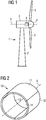
- FIG. 1 schematically shows a wind turbine 1.
- the wind turbine 1 comprises a tower 2, a nacelle 3 and a hub 4.
- the nacelle 3 is located on top of the tower 2.
- the hub 4 comprises a number of wind turbine blades 5.
- the hub 4 is mounted to the nacelle 3.
- the hub 4 is pivot-mounted such that it is able to rotate about a rotation axis 9.
- a generator 6 is located inside the nacelle 3.
- the wind turbine 1 is a direct drive wind turbine.
- FIG. 2 schematically shows an inventive nacelle shell structure in a perspective view.
- the nacelle shell structure 10 comprises a top sub-structure 11, a first side sub-structure 11, a second side sub-structure 13 and an end sub-structure 14.
- the top sub-structure 11 and the two side sub-structures 12 and 13 have a single curved shape.
- the side sub-structures 12 and 13 and the top sub-structure 11 are directly connected to each other, for example at a number of connection points or connection faces.
- the top sub-structure 11 and the two side sub-structures 12 and 13 are connected to each other such that they form a structure with a shape of a hollow cylinder.
- One of the open sides of the hollow cylinder is closed by connecting the end sub-structure 14 to the top sub-structure and the two side sub-structures 12 and 13, for example by connecting the end sub-structure 14 to the side faces of the top sub-structure 11 and to the side faces of the side sub-structures 12 and 13.
- FIG 3 schematically shows a variant of the nacelle shell structure 20 in a perspective view.
- the nacelle shell structure 20 comprises two side sub-structures 22 and 23 and a bottom sub-structure 25. It further comprises an end sub-structure 24.
- the side sub-structures 22 and 23 and the bottom sub-structure 25 have a single curved shape.
- the side sub-structures 22 and 23 and the bottom sub-structure 25 are connected to each other at a number of connection points or at connection faces. They are connected to each other such that they form a hollow cylinder, as described in conjunction with Figure 2 .
- the end sub-structure 24 is connected to the side sub-structures 22 and 23 and to the bottom sub-structure 25 in the same way as the end sub-structure 14 in Figure 2 is connected to the top sub-structure 11 and the side sub-structures 12 and 13.
- the bottom sub-structure 25 in Figure 3 comprises a circular flange 26.
- the circular flange 26 may be used to attach the nacelle or the nacelle shell structure 20 to another component of the wind turbine 1, for example to the tower 2 or to the generator 6.
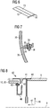
- Figure 4 schematically shows a connection between to sub-structures in a sectional view.
- Figure 4 schematically shows a possible collection between the side sub-structure 13 and the top sub-structure 11 of Figure 2 .
- the side sub-structure 13 comprises a male face 27.
- the male face 27 protrudes the top sub-structure 11 inside of the nacelle shell structure.
- the portion of the top sub-structure, where the male face 27 protrudes the top sub-structure 11, the top sub-structure 11 has an increased thickness.
- the male face 27 and the portion of the top sub-structure 11 with an increased sickness are connected to each other by means of a screw 28.
- Figure 5 schematically shows an alternative connection between two sub-structures in a sectional view.
- Figure 5 schematically shows a connection between the two side sub-structures 22 and 23 of Figure 3 at the top of the nacelle shell structure.
- the side sub-structure 22 comprises a male face 29.
- the male face 29 has an U-shape.
- the U-shaped male face 29 forms a channel with an opening towards the outside of the nacelle shell structure.
- the second side sub-structure 23 comprises a male face 30.
- the male face 30 is formed by means of the portion of the side sub-structure 23 which has an increased thickness.
- the side sub-structure 23 further comprises a recess 31 or groove-like depression. This recess or groove-like depression 31 forms a channel or a groove with an opening towards the inside of the nacelle shell structure.
- the male face 30 of the side sub-structure 23 extends into the opening or channel formed by the male face 29 of the side sub-structure 22. A part of the male face 29 extends into the recess 31.
- the male face 30 and the male face 29 are connected to each other by means of a screw 28.
- Figure 6 schematically shows the collection between the two side sub-structures 12 and 13 of Figure 2 at the bottom of the nacelle shell structure.
- a chamfer for example for leading water and/or dirt out of the nacelle shell structure, if connected to the side sub-structures 12 and 13.
- FIG. 7 schematically shows an alternative connection between two shell sub-structures 35 and 36 in a sectional view.
- the shell sub-structure 35 comprises a flange 33.
- the shell sub-structure 36 comprises a flange 34.
- the shell sub-structures 35 and 36 are connected to each other at the flanges 33 and 34 by means of screws 28 and nuts 38.
- FIG 8 schematically shows an inventive lock-labyrinth in a sectional view.
- the lock-labyrinth 50 is positioned between a generator 6 and a nacelle shell structure 10 or 20.
- the nacelle shell structure 10, 20 comprises a water-tight channel or circular support structure 40.
- the water-tight channel or circular support structure 40 is connected to the nacelle shell structure 10, 20 by means of screws and nuts 43.
- the water-tight channel or circular support structure 40 has an U-shape.
- the U-shaped structure opens radially outwards. The radial direction is indicated by an arrow 46.
- a shield sub-structure 41 is connected to the generator 6.
- the joint is indicated by the reference numeral 44.
- the shield sub-structure 41 comprises a nose 42.
- the nose 42 extends radially inward towards the rotation axis 9.
- the shield sub-structure 41 protrudes the water-tight channel or circular support structure 40 in axial direction 47.
- the nose 42 and the circular support structure or water-tight channel 40 are positioned such that the nose 42 has an axial position where it extends towards the inside of the channel formed by the circular support structure or by the water-tight channel 40. This means that the nose 42 protrudes radially inward at an axial position where the support structure forms a water-tight channel 40 which opens towards the nose 42.
- the shield sub-structure 41 protrudes the nacelle shell structure 10, 20 such that a gap 45 is located between the shield sub-structure 41 and the nacelle shell structure 10, 20.
- a water or dirt which enters the gap 45 is led into the water-tight channel 40 by means of the nose 42.
- the water-tight channel 40 leads the water or dirt out of the nacelle 3.
Landscapes
- Engineering & Computer Science (AREA)
- Life Sciences & Earth Sciences (AREA)
- Sustainable Development (AREA)
- Sustainable Energy (AREA)
- Chemical & Material Sciences (AREA)
- Combustion & Propulsion (AREA)
- Mechanical Engineering (AREA)
- General Engineering & Computer Science (AREA)
- Power Engineering (AREA)
- Wind Motors (AREA)
- Sealing Using Fluids, Sealing Without Contact, And Removal Of Oil (AREA)
Description
- Nacelle shell structure, lock labyrinth and wind turbine The present invention relates to a nacelle shell structure, to a lock labyrinth and to a wind turbine.
- The document Erich Hau: "Windkraftanlagen", Springer-Verlag Berlin ISBN: 3-540-57430-1, pages 266-267 is related to the construction of a wind turbine nacelle. The document
US 2008 317 582 A1 discloses a wind-powered turbine comprising cupped rotors. Thedocument DE 10 2007 012 408 A1 discloses a gearbox wind turbine.EP 2 108 833 A2 - A nacelle shell structure usually consists of multiple shell structure elements. The known prior art is to attach each of these nacelle shell elements to a nacelle lattice structure or a nacelle supporting structure e.g. by welding or by screwing the elements to the structure. The lattice structure may be anchored e.g. to a nacelle bedplate.
- A difficulty related to this prior art is, that a separate lattice structure has to be build up around the nacelle components in order to hold the shell elements. A further disadvantage is that all vibrations, deformations, stresses etc. are transferred from e.g. the nacelle bedplate to which the lattice structure is anchored and further transferred to the nacelle shell elements. This in turn increases the risk of material fatigue.
- It is an objective of the present invention to provide a direct drive wind turbine, which reduces a transfer of vibrations, deformations or stresses between a main structure and a nacelle shell structure.
- The objective is solved by a direct drive wind turbine as claimed in
claim 1. The depending claims define further developments of the invention. - In the frame work of the present invention the words nacelle shell and canopy are used synonymously.
- The inventive direct drive wind turbine comprises a main structure and a nacelle shell structure. The inventive nacelle shell structure is attached to a main structure of the direct drive wind turbine such that the nacelle shell structure is carried by the main structure at only three static points.
- The nacelle shell structure may be directly connected to the main structure. Alternatively, the nacelle shell structure may be connected to the main structure by means of at least one sectional bar. For example, the nacelle shell structure can be attachable to a wind turbine tower. By constructing the nacelle shell structure such that it is carried by the main structure in substantially three points only, it is possible to build the nacelle shell structure as a static stable construction. This means that the construction is static defined. Stresses from the supporting structure are hereby substantially not or only very minimally transferred to the shell structure which in turn is secured for fatigue.
- The three static points may be three physical points. By static points are meant points or areas on the nacelle shell structure or canopy structure which, static wise, can be regarded as one point and between which substantially no static differences are present. This means, that a static stable point may actually be multiple physical points, which are often located close to each other and which can, calculating the static's, be regarded as one point.
- For a preferred embodiment, the nacelle shell structure is attached to and carried by the main structure of the wind turbine in substantially three static stable points only. Said three points provide a static stable construction, i.e. a static defined construction. Stresses from the supporting structure are hereby substantially not or only very minimally transferred to the shell structure which in turn is secured for fatigue.
- The nacelle shell structure can be directly connectable to the main structure. Alternatively, the nacelle shell structure may be connectable to the main structure by means of at least one sectional bar. Advantageously, the nacelle shell structure can be connectable to the main structure by means of three sectional bars. Each sectional bar can be connectable to one of the static points and to the main structure.
- The nacelle shell structure is attached to the main structure of the wind turbine, for example, a wind turbine tower. The nacelle shell structure comprises a number of interconnected shell sub-structures.
- The shell sub-structures may be directly connected to each other at a number of connection points. Preferably, the interconnected shell sub-structures may be self-supporting. As the shell structure is built of two or more sub-structures which for various embodiments form a self-supporting shell structure, it is ensured that no or substantially no additional lattice structure are needed for supporting the shell structure. This is cost-effective as only little material is used.
- Furthermore, as the nacelle shell structure or canopy is divided into multiple sub-structures it is ensured that the nacelle shell structure or canopy does not have to be transported in one piece and therefore the requirements to transport vehicles etc. is limited. This in turn is also cost-effective.
- Moreover, the nacelle shells structure may comprise a flange for supporting the nacelle shell structure and/or for connecting the nacelle shell structure to the main structure of the wind turbine or to a generator. Preferably, the flange may be a circular flange.
- The nacelle shell structure may comprise a top sub-structure and/or a side-sub-structure and/or an end-sub-structure. Generally, the sub-structures may be interconnected by means of bolts and screws.
- Furthermore, the sub-structures can be single curved. Moreover, the sub-structures may comprise at least one single curved portion. This provides for an easy and cost-effective manufacturing of the needed sub-structures.
- Generally, the nacelle shell structure can comprise glass-fibre. Preferably, the nacelle shell structure is reinforced at at least one of the static points.
- Generally, all mentioned features can be combined with each other. For example, the nacelle shell structure which is attachable to the main structure such that the nacelle shell structure is carried by the main structure at only three static points, as previously described, may comprise a number of interconnected shell sub-structures, as also previously described.
- The nacelle shell structures may be reinforced at the points where it is connectable to the main structure of the wind turbine.
- The lock-labyrinths for positioning between a rotating part with a rotation axis and a stationary part of a wind turbine comprises a shield structure and a support structure. The shield structure is located radially outward of the support structure. The radius is related to the rotation axis of the rotating part of the wind turbine. The shield structure protrudes the support structure in axial direction. The axial direction is related to the rotation axis of the rotating part. The shield structure comprises a nose.
- the wind turbine or to a generator. Preferably, the flange may be a circular flange.
- The nacelle shell structure may comprise a top sub-structure and/or a side-sub-structure and/or an end-sub-structure. Generally, the sub-structures may be interconnected by means of bolts and screws.
- Furthermore, the sub-structures can be single curved. Moreover, the sub-structures may comprise at least one single curved portion. This provides for an easy and cost-effective manufacturing of the needed sub-structures.
- Generally, the nacelle shell structure can comprise glass-fibre. Preferably, the nacelle shell structure is reinforced at at least one of the static points.
- Generally, all mentioned features can be combined with each other. For example, the nacelle shell structure which is attachable to the main structure such that the nacelle shell structure is carried by the main structure at only three static points, as previously described, may comprise a number of interconnected shell sub-structures, as also previously described.
- The nacelle shell structures may be reinforced at the points where it is connectable to the main structure of the wind turbine.
- The lock-labyrinths for positioning between a rotating part with a rotation axis and a stationary part of a wind turbine comprises a shield structure and a support structure. The shield structure is located radially outward of the support structure. The radius is related to the rotation axis of the rotating part of the wind turbine. The shield structure protrudes the support structure in axial direction. The axial direction is related to the rotation axis of the rotating part. The shield structure comprises a nose.
- Generally, the previously described nacelle shell structure may comprise an inventive lock-labyrinth.
- The water-tight channel can be a circular support structure. In this case, the water-tight channel or circular support structure can be identical to or part of the previously mentioned circular flange of the inventive nacelle shell structure.
- Further features, properties and advantages of the present invention will become clear from the following description of embodiments in conjunction with the accompanying drawings. All mentioned features and properties are advantageous alone or in any combination with each other.
- Figure 1
- schematically shows a wind turbine.
- Figure 2
- schematically shows a nacelle shell structure in a perspective view.
- Figure 3
- schematically shows a nacelle shell structure with a circular flange in a perspective view.
- Figure 4
- schematically shows a connection between two shell sub-structures in a sectional view.
- Figure 5
- schematically shows a variant of a connection between two shell sub-structures in a sectional view.
- Figure 6
- schematically shows a connection between two substructures in a perspective view.
- Figure 7
- schematically shows a further variant of a connection between two shell sub-structures in a sectional view.
- Figure 8
- schematically shows a lock-labyrinth in a sectional view.
- A first embodiment of the present invention will now be described with reference to
Figures 1 to 7 . -
Figure 1 schematically shows awind turbine 1. Thewind turbine 1 comprises atower 2, a nacelle 3 and ahub 4. The nacelle 3 is located on top of thetower 2. Thehub 4 comprises a number ofwind turbine blades 5. Thehub 4 is mounted to the nacelle 3. Moreover, thehub 4 is pivot-mounted such that it is able to rotate about arotation axis 9. Agenerator 6 is located inside the nacelle 3. Thewind turbine 1 is a direct drive wind turbine. -
Figure 2 schematically shows an inventive nacelle shell structure in a perspective view. Thenacelle shell structure 10 comprises atop sub-structure 11, afirst side sub-structure 11, a second side sub-structure 13 and anend sub-structure 14. Thetop sub-structure 11 and the twoside sub-structures - The side sub-structures 12 and 13 and the
top sub-structure 11 are directly connected to each other, for example at a number of connection points or connection faces. Thetop sub-structure 11 and the twoside sub-structures side sub-structures top sub-structure 11 and to the side faces of theside sub-structures -
Figure 3 schematically shows a variant of thenacelle shell structure 20 in a perspective view. Thenacelle shell structure 20 comprises twoside sub-structures bottom sub-structure 25. It further comprises anend sub-structure 24. The side sub-structures 22 and 23 and thebottom sub-structure 25 have a single curved shape. The side sub-structures 22 and 23 and thebottom sub-structure 25 are connected to each other at a number of connection points or at connection faces. They are connected to each other such that they form a hollow cylinder, as described in conjunction withFigure 2 . Theend sub-structure 24 is connected to theside sub-structures bottom sub-structure 25 in the same way as theend sub-structure 14 inFigure 2 is connected to thetop sub-structure 11 and theside sub-structures - The
bottom sub-structure 25 inFigure 3 comprises acircular flange 26. Thecircular flange 26 may be used to attach the nacelle or thenacelle shell structure 20 to another component of thewind turbine 1, for example to thetower 2 or to thegenerator 6. -
Figure 4 schematically shows a connection between to sub-structures in a sectional view. As an example,Figure 4 schematically shows a possible collection between the side sub-structure 13 and thetop sub-structure 11 ofFigure 2 . InFigure 4 the side sub-structure 13 comprises amale face 27. Themale face 27 protrudes thetop sub-structure 11 inside of the nacelle shell structure. The portion of the top sub-structure, where themale face 27 protrudes thetop sub-structure 11, thetop sub-structure 11 has an increased thickness. Themale face 27 and the portion of thetop sub-structure 11 with an increased sickness are connected to each other by means of ascrew 28. -
Figure 5 schematically shows an alternative connection between two sub-structures in a sectional view. As an exampleFigure 5 schematically shows a connection between the twoside sub-structures Figure 3 at the top of the nacelle shell structure. InFigure 5 the side sub-structure 22 comprises amale face 29. Themale face 29 has an U-shape. The U-shapedmale face 29 forms a channel with an opening towards the outside of the nacelle shell structure. The second side sub-structure 23 comprises amale face 30. Themale face 30 is formed by means of the portion of the side sub-structure 23 which has an increased thickness. The side sub-structure 23 further comprises arecess 31 or groove-like depression. This recess or groove-like depression 31 forms a channel or a groove with an opening towards the inside of the nacelle shell structure. - The
male face 30 of the side sub-structure 23 extends into the opening or channel formed by themale face 29 of theside sub-structure 22. A part of themale face 29 extends into therecess 31. Themale face 30 and themale face 29 are connected to each other by means of ascrew 28. -
Figure 6 schematically shows the collection between the twoside sub-structures Figure 2 at the bottom of the nacelle shell structure. At the backside, where the twoside sub-structures end sub-structure 14, a chamfer for example for leading water and/or dirt out of the nacelle shell structure, if connected to theside sub-structures -
Figure 7 schematically shows an alternative connection between twoshell sub-structures shell sub-structure 35 comprises aflange 33. Theshell sub-structure 36 comprises aflange 34. The shell sub-structures 35 and 36 are connected to each other at theflanges screws 28 and nuts 38. - All connections described in
Figures 4 to 7 can be used to connect any of the described sub-structures with any other of the described sub-structures. - A second embodiment of the present invention will now be described with reference to
Figures 1 and8 . -
Figure 8 schematically shows an inventive lock-labyrinth in a sectional view. InFigure 8 the lock-labyrinth 50 is positioned between agenerator 6 and anacelle shell structure nacelle shell structure circular support structure 40. The water-tight channel orcircular support structure 40 is connected to thenacelle shell structure circular support structure 40 has an U-shape. The U-shaped structure opens radially outwards. The radial direction is indicated by anarrow 46. - A
shield sub-structure 41 is connected to thegenerator 6. The joint is indicated by thereference numeral 44. Theshield sub-structure 41 comprises anose 42. Thenose 42 extends radially inward towards therotation axis 9. The shield sub-structure 41 protrudes the water-tight channel orcircular support structure 40 inaxial direction 47. Thenose 42 and the circular support structure or water-tight channel 40 are positioned such that thenose 42 has an axial position where it extends towards the inside of the channel formed by the circular support structure or by the water-tight channel 40. This means that thenose 42 protrudes radially inward at an axial position where the support structure forms a water-tight channel 40 which opens towards thenose 42. - The shield sub-structure 41 protrudes the
nacelle shell structure gap 45 is located between theshield sub-structure 41 and thenacelle shell structure gap 45 is led into the water-tight channel 40 by means of thenose 42. The water-tight channel 40 leads the water or dirt out of the nacelle 3. By using the described lock-labyrinth 50 dirt or water, especially rain water can not enter the inside of the nacelle 3.
Claims (12)
- A direct drive wind turbine (1) comprising a nacelle shell structure (10, 20) and a main structure (2), wherein the nacelle shell structure (10, 20) is attachable to the main structure (2) of the direct drive wind turbine (1),
characterised in that
the nacelle shell structure (10, 20) is attached to the main structure (2) such that the nacelle shell structure (10, 20) is carried by the main structure (2) at only three static points. - The direct drive wind turbine (1) as claimed in claim 1,
characterised in that
the three static points are three physical points. - The direct drive wind turbine (1) as claimed in claim 1 or 2,
characterised in that
the nacelle shell structure (10, 20) is directly connected to the main structure (2) or the nacelle shell structure (10, 20) is connected to the main structure (2) by means of at least one sectional bar. - The direct drive wind turbine (1) as claimed in any of the claims 1 to 3,
characterised in that
the nacelle shell structure (10, 20) comprises a number of interconnected shell sub-structures (11, 12, 13, 14, 22, 23, 24, 25, 35, 36). - The direct drive wind turbine (1) as claimed in claim 4,
characterised in that
the interconnected shell sub-structures (11, 12, 13, 14, 22, 23, 24, 25, 35, 36) are self-supporting. - The direct drive wind turbine (1) as claimed in claim 4 or 5,
characterised in that
the nacelle shell structure (10, 20) comprises a flange (26) for supporting the nacelle shell structure (10, 20) and/or for connecting the nacelle shell structure (10, 20) to the main structure (2) of the wind turbine (1) or to a generator (6) . - The direct drive wind turbine (1) as claimed in claim 6,
characterised in that
the flange (26) is a circular flange. - The direct drive wind turbine (1) as claimed in any of the claims 4 to 7,
characterised in that
the sub-structures (11, 12, 13, 14, 22, 23, 24, 25, 35, 36) are single curved or comprise at least one single curved portion. - The direct drive wind turbine (1) as claimed in any of the claims 1 to 8,
characterised in that
the nacelle shell structure (10, 20) comprises glass-fibre and/or is reinforced at at least one of the static points. - The direct drive wind turbine (1) as claimed in any of the claims 1 to 9,
characterised in that
nacelle shell structure (10, 20) comprises a lock-labyrinth (50) for positioning between a rotating part with a rotation axis (9) and stationary part of a wind turbine (1), which comprises a shield structure (41) and a support structure (40), the shield structure (41) being located radially outward of the support structure (40) and protruding the support structure (40) in axial direction (47),
wherein the shield structure (41) comprises a nose (42) protruding radially inward and being located at an axial position where the support structure (40) forms a water-tight channel which opens towards the nose (42). - The direct drive wind turbine (1) as claimed in claim 10,
characterised in that
the rotating part comprises a generator (6) and/or the stationary part comprises a nacelle (3) or a nacelle shell structure (10, 20) or a nacelle shell sub-structure (11, 12, 13, 14, 22, 23, 24, 25, 35, 36). - The direct drive wind turbine (1) as claimed in claim 10 or 11,
characterised in that
lock-labyrinth (50) comprises a gap (45) between the rotating part and the stationary part.
Priority Applications (3)
| Application Number | Priority Date | Filing Date | Title |
|---|---|---|---|
| EP15002976.7A EP3006730B8 (en) | 2009-11-25 | 2010-09-16 | Lock labyrinth, nacelle shell structure and wind turbine |
| EP10754510.5A EP2504573B1 (en) | 2009-11-25 | 2010-09-16 | Nacelle shell structure |
| DK15002976.7T DK3006730T3 (en) | 2009-11-25 | 2010-09-16 | SECURITY LABYRINE, NACELL SCALE CONSTRUCTION AND WIND MILL |
Applications Claiming Priority (3)
| Application Number | Priority Date | Filing Date | Title |
|---|---|---|---|
| EP09014701 | 2009-11-25 | ||
| PCT/EP2010/063641 WO2011064006A2 (en) | 2009-11-25 | 2010-09-16 | Nacelle shell structure, lock labyrinth and wind turbine |
| EP10754510.5A EP2504573B1 (en) | 2009-11-25 | 2010-09-16 | Nacelle shell structure |
Related Child Applications (2)
| Application Number | Title | Priority Date | Filing Date |
|---|---|---|---|
| EP15002976.7A Division EP3006730B8 (en) | 2009-11-25 | 2010-09-16 | Lock labyrinth, nacelle shell structure and wind turbine |
| EP15002976.7A Division-Into EP3006730B8 (en) | 2009-11-25 | 2010-09-16 | Lock labyrinth, nacelle shell structure and wind turbine |
Publications (2)
| Publication Number | Publication Date |
|---|---|
| EP2504573A2 EP2504573A2 (en) | 2012-10-03 |
| EP2504573B1 true EP2504573B1 (en) | 2020-06-10 |
Family
ID=44066978
Family Applications (2)
| Application Number | Title | Priority Date | Filing Date |
|---|---|---|---|
| EP10754510.5A Active EP2504573B1 (en) | 2009-11-25 | 2010-09-16 | Nacelle shell structure |
| EP15002976.7A Active EP3006730B8 (en) | 2009-11-25 | 2010-09-16 | Lock labyrinth, nacelle shell structure and wind turbine |
Family Applications After (1)
| Application Number | Title | Priority Date | Filing Date |
|---|---|---|---|
| EP15002976.7A Active EP3006730B8 (en) | 2009-11-25 | 2010-09-16 | Lock labyrinth, nacelle shell structure and wind turbine |
Country Status (5)
| Country | Link |
|---|---|
| US (1) | US9541069B2 (en) |
| EP (2) | EP2504573B1 (en) |
| CN (2) | CN102695876B (en) |
| DK (1) | DK3006730T3 (en) |
| WO (1) | WO2011064006A2 (en) |
Families Citing this family (10)
| Publication number | Priority date | Publication date | Assignee | Title |
|---|---|---|---|---|
| EP2604892B1 (en) | 2011-12-13 | 2017-02-01 | Siemens Aktiengesellschaft | Sealing arrangement for a wind turbine |
| KR101723718B1 (en) * | 2011-12-21 | 2017-04-05 | 보벤 프로퍼티즈 게엠베하 | Wind turbine nacelle |
| US8966831B1 (en) * | 2013-03-06 | 2015-03-03 | Chad Stoll | Hunting blind |
| JP6373149B2 (en) * | 2014-09-30 | 2018-08-15 | 株式会社日立製作所 | Wind power generator |
| DE102016206179A1 (en) * | 2016-04-13 | 2017-10-19 | Wobben Properties Gmbh | Generator rotor for a generator of a wind turbine or a hydroelectric power plant, and generator, wind turbine and hydroelectric power plant with selbigem |
| CN106286156A (en) * | 2016-08-30 | 2017-01-04 | 优利康达(天津)科技有限公司 | A kind of dust-proof cabin cover |
| DE102017004291A1 (en) * | 2017-05-04 | 2018-11-08 | Senvion Gmbh | Housing for a nacelle of a wind turbine |
| DK3533999T3 (en) * | 2018-03-02 | 2022-12-05 | Siemens Gamesa Renewable Energy As | Cabin structure and a windmill |
| EP3611372A1 (en) * | 2018-08-13 | 2020-02-19 | youWINenergy GmbH | Nacelle for a wind turbine installation, wind turbine installation with the nacelle and method to assemble the wind turbine installation |
| EP3869032B1 (en) * | 2020-02-20 | 2024-04-10 | Siemens Gamesa Renewable Energy Innovation & Technology, S.L. | Seal for a wind turbine nacelle |
Family Cites Families (18)
| Publication number | Priority date | Publication date | Assignee | Title |
|---|---|---|---|---|
| US3900116A (en) * | 1972-09-05 | 1975-08-19 | Exxon Nuclear Co Inc | Fuel element shipping shim for nuclear reactor |
| US4819398A (en) * | 1987-11-20 | 1989-04-11 | Dameron Joseph T | Improved roof panel apparatus and panel locking method |
| US5893395A (en) * | 1995-04-28 | 1999-04-13 | Davis; A. Eugene | Formed ragglestick |
| CN2338236Y (en) * | 1998-06-10 | 1999-09-15 | 韩永林 | Portable bicycle front basket |
| FR2817290B1 (en) * | 2000-11-30 | 2003-02-21 | Snecma Moteurs | ROTOR BLADE DISC FLANGE AND CORRESPONDING ARRANGEMENT |
| EP1429025B1 (en) * | 2001-12-28 | 2013-11-27 | Mitsubishi Heavy Industries, Ltd. | Up-wind type windmill and operating method therefor |
| DE10340560A1 (en) * | 2003-09-01 | 2005-04-07 | Haase Gfk-Technik Gmbh | Method for constructing housings or enclosures, in particular, for wind power generating installations involves use of three basic types of sandwich-structured modules |
| DE602006013011D1 (en) | 2005-09-21 | 2010-04-29 | High Technology Invest Bv | BEARING SEALING ASSEMBLY WITH LABYRINTH SEALING AND SCREW SEALING COMBINATION |
| ATE535984T1 (en) | 2006-03-30 | 2011-12-15 | Clipper Windpower Llc | ELECTRIC GENERATOR FOR WIND AND WATER TURBINES |
| US20080317582A1 (en) | 2007-01-11 | 2008-12-25 | Cassidy Joe C | Vertical axis dual vortex downwind inward flow impulse wind turbine |
| DE102007003618A1 (en) | 2007-01-18 | 2008-07-24 | Voith Patent Gmbh | Power generation plant driven by a wind or water flow |
| DE102007012408A1 (en) * | 2007-03-15 | 2008-09-18 | Aerodyn Engineering Gmbh | Wind turbines with load-transmitting components |
| DE102007018025A1 (en) * | 2007-04-17 | 2008-10-23 | Nordex Energy Gmbh | Wind turbine tower |
| US7538446B2 (en) | 2007-06-21 | 2009-05-26 | General Electric Company | Gear integrated generator for wind turbine |
| US8047804B2 (en) * | 2007-12-27 | 2011-11-01 | General Electric Company | Wind tower and method of assembling the same |
| US8083464B2 (en) * | 2008-01-29 | 2011-12-27 | General Electric Company | Stackable nacelle for wind turbines |
| CN201162631Y (en) | 2008-03-19 | 2008-12-10 | 无锡利保科技发展有限公司 | Macrotype wind turbine cabinet cover |
| CN201292915Y (en) | 2008-10-31 | 2009-08-19 | 北京中新图锐科技有限公司 | Wind-driven generator hood |
-
2010
- 2010-09-16 DK DK15002976.7T patent/DK3006730T3/en active
- 2010-09-16 CN CN201080053525.1A patent/CN102695876B/en active Active
- 2010-09-16 WO PCT/EP2010/063641 patent/WO2011064006A2/en active Application Filing
- 2010-09-16 CN CN201510099418.7A patent/CN104775992B/en active Active
- 2010-09-16 US US13/511,473 patent/US9541069B2/en active Active
- 2010-09-16 EP EP10754510.5A patent/EP2504573B1/en active Active
- 2010-09-16 EP EP15002976.7A patent/EP3006730B8/en active Active
Non-Patent Citations (1)
| Title |
|---|
| None * |
Also Published As
| Publication number | Publication date |
|---|---|
| CN102695876A (en) | 2012-09-26 |
| US9541069B2 (en) | 2017-01-10 |
| EP3006730B1 (en) | 2019-04-17 |
| DK3006730T3 (en) | 2019-07-08 |
| EP3006730B8 (en) | 2019-06-19 |
| WO2011064006A3 (en) | 2011-12-01 |
| CN104775992A (en) | 2015-07-15 |
| CN102695876B (en) | 2015-08-19 |
| CN104775992B (en) | 2018-11-13 |
| WO2011064006A2 (en) | 2011-06-03 |
| US20130084177A1 (en) | 2013-04-04 |
| EP2504573A2 (en) | 2012-10-03 |
| EP3006730A1 (en) | 2016-04-13 |
Similar Documents
| Publication | Publication Date | Title |
|---|---|---|
| EP2504573B1 (en) | Nacelle shell structure | |
| US8465256B2 (en) | Wind turbine rotor | |
| US8449263B2 (en) | Segmented rotor hub assembly | |
| EP2045464B2 (en) | Pitch bearing for wind turbine rotor blades | |
| EP2933476B1 (en) | Reinforced pitch bearing of a wind turbine | |
| EP2466135A2 (en) | Reinforcement system for wind turbine tower | |
| EP2322795A2 (en) | Nacelle for a wind turbine | |
| US10330076B2 (en) | Bolted joint for rotor blade segments | |
| EP2837820B1 (en) | Segmented wind turbine hub | |
| CA2737814A1 (en) | Wall section for a wind turbine tower and wind turbine tower | |
| RU2718379C1 (en) | Connecting element for connecting sections of tower, section of tower, tower, wind-driven power plant, as well as method of making tower section and method of connecting sections of tower | |
| US8203230B2 (en) | Yaw bearing system | |
| US20140377078A1 (en) | Root stiffener for a wind turbine rotor blade | |
| US8186956B2 (en) | Semi-flexible supporting structure for wind turbine | |
| EP3568588B1 (en) | Spinner for hub of wind turbine | |
| WO2011144367A1 (en) | Wind turbine tower | |
| JP2004270578A (en) | Structure for three blade type vertical shaft windmill device |
Legal Events
| Date | Code | Title | Description |
|---|---|---|---|
| PUAI | Public reference made under article 153(3) epc to a published international application that has entered the european phase |
Free format text: ORIGINAL CODE: 0009012 |
|
| 17P | Request for examination filed |
Effective date: 20120425 |
|
| AK | Designated contracting states |
Kind code of ref document: A2 Designated state(s): AL AT BE BG CH CY CZ DE DK EE ES FI FR GB GR HR HU IE IS IT LI LT LU LV MC MK MT NL NO PL PT RO SE SI SK SM TR |
|
| DAX | Request for extension of the european patent (deleted) | ||
| RAP1 | Party data changed (applicant data changed or rights of an application transferred) |
Owner name: SIEMENS AKTIENGESELLSCHAFT |
|
| 17Q | First examination report despatched |
Effective date: 20150723 |
|
| RAP1 | Party data changed (applicant data changed or rights of an application transferred) |
Owner name: SIEMENS AKTIENGESELLSCHAFT |
|
| RAP1 | Party data changed (applicant data changed or rights of an application transferred) |
Owner name: SIEMENS GAMESA RENEWABLE ENERGY A/S |
|
| REG | Reference to a national code |
Ref country code: DE Ref legal event code: R079 Ref document number: 602010064579 Country of ref document: DE Free format text: PREVIOUS MAIN CLASS: F03D0009000000 Ipc: F03D0013200000 |
|
| RIC1 | Information provided on ipc code assigned before grant |
Ipc: F03D 13/20 20160101AFI20191128BHEP |
|
| GRAP | Despatch of communication of intention to grant a patent |
Free format text: ORIGINAL CODE: EPIDOSNIGR1 |
|
| STAA | Information on the status of an ep patent application or granted ep patent |
Free format text: STATUS: GRANT OF PATENT IS INTENDED |
|
| INTG | Intention to grant announced |
Effective date: 20200131 |
|
| GRAS | Grant fee paid |
Free format text: ORIGINAL CODE: EPIDOSNIGR3 |
|
| GRAA | (expected) grant |
Free format text: ORIGINAL CODE: 0009210 |
|
| STAA | Information on the status of an ep patent application or granted ep patent |
Free format text: STATUS: THE PATENT HAS BEEN GRANTED |
|
| AK | Designated contracting states |
Kind code of ref document: B1 Designated state(s): AL AT BE BG CH CY CZ DE DK EE ES FI FR GB GR HR HU IE IS IT LI LT LU LV MC MK MT NL NO PL PT RO SE SI SK SM TR |
|
| REG | Reference to a national code |
Ref country code: GB Ref legal event code: FG4D |
|
| REG | Reference to a national code |
Ref country code: CH Ref legal event code: EP Ref country code: AT Ref legal event code: REF Ref document number: 1279396 Country of ref document: AT Kind code of ref document: T Effective date: 20200615 |
|
| REG | Reference to a national code |
Ref country code: DE Ref legal event code: R096 Ref document number: 602010064579 Country of ref document: DE |
|
| REG | Reference to a national code |
Ref country code: IE Ref legal event code: FG4D |
|
| REG | Reference to a national code |
Ref country code: LT Ref legal event code: MG4D |
|
| PG25 | Lapsed in a contracting state [announced via postgrant information from national office to epo] |
Ref country code: GR Free format text: LAPSE BECAUSE OF FAILURE TO SUBMIT A TRANSLATION OF THE DESCRIPTION OR TO PAY THE FEE WITHIN THE PRESCRIBED TIME-LIMIT Effective date: 20200911 Ref country code: FI Free format text: LAPSE BECAUSE OF FAILURE TO SUBMIT A TRANSLATION OF THE DESCRIPTION OR TO PAY THE FEE WITHIN THE PRESCRIBED TIME-LIMIT Effective date: 20200610 Ref country code: SE Free format text: LAPSE BECAUSE OF FAILURE TO SUBMIT A TRANSLATION OF THE DESCRIPTION OR TO PAY THE FEE WITHIN THE PRESCRIBED TIME-LIMIT Effective date: 20200610 Ref country code: NO Free format text: LAPSE BECAUSE OF FAILURE TO SUBMIT A TRANSLATION OF THE DESCRIPTION OR TO PAY THE FEE WITHIN THE PRESCRIBED TIME-LIMIT Effective date: 20200910 Ref country code: LT Free format text: LAPSE BECAUSE OF FAILURE TO SUBMIT A TRANSLATION OF THE DESCRIPTION OR TO PAY THE FEE WITHIN THE PRESCRIBED TIME-LIMIT Effective date: 20200610 |
|
| REG | Reference to a national code |
Ref country code: NL Ref legal event code: MP Effective date: 20200610 |
|
| PG25 | Lapsed in a contracting state [announced via postgrant information from national office to epo] |
Ref country code: BG Free format text: LAPSE BECAUSE OF FAILURE TO SUBMIT A TRANSLATION OF THE DESCRIPTION OR TO PAY THE FEE WITHIN THE PRESCRIBED TIME-LIMIT Effective date: 20200910 Ref country code: HR Free format text: LAPSE BECAUSE OF FAILURE TO SUBMIT A TRANSLATION OF THE DESCRIPTION OR TO PAY THE FEE WITHIN THE PRESCRIBED TIME-LIMIT Effective date: 20200610 Ref country code: LV Free format text: LAPSE BECAUSE OF FAILURE TO SUBMIT A TRANSLATION OF THE DESCRIPTION OR TO PAY THE FEE WITHIN THE PRESCRIBED TIME-LIMIT Effective date: 20200610 |
|
| REG | Reference to a national code |
Ref country code: AT Ref legal event code: MK05 Ref document number: 1279396 Country of ref document: AT Kind code of ref document: T Effective date: 20200610 |
|
| PG25 | Lapsed in a contracting state [announced via postgrant information from national office to epo] |
Ref country code: NL Free format text: LAPSE BECAUSE OF FAILURE TO SUBMIT A TRANSLATION OF THE DESCRIPTION OR TO PAY THE FEE WITHIN THE PRESCRIBED TIME-LIMIT Effective date: 20200610 Ref country code: AL Free format text: LAPSE BECAUSE OF FAILURE TO SUBMIT A TRANSLATION OF THE DESCRIPTION OR TO PAY THE FEE WITHIN THE PRESCRIBED TIME-LIMIT Effective date: 20200610 |
|
| PG25 | Lapsed in a contracting state [announced via postgrant information from national office to epo] |
Ref country code: AT Free format text: LAPSE BECAUSE OF FAILURE TO SUBMIT A TRANSLATION OF THE DESCRIPTION OR TO PAY THE FEE WITHIN THE PRESCRIBED TIME-LIMIT Effective date: 20200610 Ref country code: EE Free format text: LAPSE BECAUSE OF FAILURE TO SUBMIT A TRANSLATION OF THE DESCRIPTION OR TO PAY THE FEE WITHIN THE PRESCRIBED TIME-LIMIT Effective date: 20200610 Ref country code: SM Free format text: LAPSE BECAUSE OF FAILURE TO SUBMIT A TRANSLATION OF THE DESCRIPTION OR TO PAY THE FEE WITHIN THE PRESCRIBED TIME-LIMIT Effective date: 20200610 Ref country code: PT Free format text: LAPSE BECAUSE OF FAILURE TO SUBMIT A TRANSLATION OF THE DESCRIPTION OR TO PAY THE FEE WITHIN THE PRESCRIBED TIME-LIMIT Effective date: 20201012 Ref country code: CZ Free format text: LAPSE BECAUSE OF FAILURE TO SUBMIT A TRANSLATION OF THE DESCRIPTION OR TO PAY THE FEE WITHIN THE PRESCRIBED TIME-LIMIT Effective date: 20200610 Ref country code: IT Free format text: LAPSE BECAUSE OF FAILURE TO SUBMIT A TRANSLATION OF THE DESCRIPTION OR TO PAY THE FEE WITHIN THE PRESCRIBED TIME-LIMIT Effective date: 20200610 Ref country code: ES Free format text: LAPSE BECAUSE OF FAILURE TO SUBMIT A TRANSLATION OF THE DESCRIPTION OR TO PAY THE FEE WITHIN THE PRESCRIBED TIME-LIMIT Effective date: 20200610 Ref country code: RO Free format text: LAPSE BECAUSE OF FAILURE TO SUBMIT A TRANSLATION OF THE DESCRIPTION OR TO PAY THE FEE WITHIN THE PRESCRIBED TIME-LIMIT Effective date: 20200610 |
|
| PG25 | Lapsed in a contracting state [announced via postgrant information from national office to epo] |
Ref country code: PL Free format text: LAPSE BECAUSE OF FAILURE TO SUBMIT A TRANSLATION OF THE DESCRIPTION OR TO PAY THE FEE WITHIN THE PRESCRIBED TIME-LIMIT Effective date: 20200610 Ref country code: SK Free format text: LAPSE BECAUSE OF FAILURE TO SUBMIT A TRANSLATION OF THE DESCRIPTION OR TO PAY THE FEE WITHIN THE PRESCRIBED TIME-LIMIT Effective date: 20200610 Ref country code: IS Free format text: LAPSE BECAUSE OF FAILURE TO SUBMIT A TRANSLATION OF THE DESCRIPTION OR TO PAY THE FEE WITHIN THE PRESCRIBED TIME-LIMIT Effective date: 20201010 |
|
| REG | Reference to a national code |
Ref country code: DE Ref legal event code: R097 Ref document number: 602010064579 Country of ref document: DE |
|
| PLBE | No opposition filed within time limit |
Free format text: ORIGINAL CODE: 0009261 |
|
| STAA | Information on the status of an ep patent application or granted ep patent |
Free format text: STATUS: NO OPPOSITION FILED WITHIN TIME LIMIT |
|
| PG25 | Lapsed in a contracting state [announced via postgrant information from national office to epo] |
Ref country code: MC Free format text: LAPSE BECAUSE OF FAILURE TO SUBMIT A TRANSLATION OF THE DESCRIPTION OR TO PAY THE FEE WITHIN THE PRESCRIBED TIME-LIMIT Effective date: 20200610 Ref country code: DK Free format text: LAPSE BECAUSE OF FAILURE TO SUBMIT A TRANSLATION OF THE DESCRIPTION OR TO PAY THE FEE WITHIN THE PRESCRIBED TIME-LIMIT Effective date: 20200610 |
|
| REG | Reference to a national code |
Ref country code: CH Ref legal event code: PL |
|
| 26N | No opposition filed |
Effective date: 20210311 |
|
| PG25 | Lapsed in a contracting state [announced via postgrant information from national office to epo] |
Ref country code: SI Free format text: LAPSE BECAUSE OF FAILURE TO SUBMIT A TRANSLATION OF THE DESCRIPTION OR TO PAY THE FEE WITHIN THE PRESCRIBED TIME-LIMIT Effective date: 20200610 |
|
| REG | Reference to a national code |
Ref country code: BE Ref legal event code: MM Effective date: 20200930 |
|
| PG25 | Lapsed in a contracting state [announced via postgrant information from national office to epo] |
Ref country code: LU Free format text: LAPSE BECAUSE OF NON-PAYMENT OF DUE FEES Effective date: 20200916 |
|
| PG25 | Lapsed in a contracting state [announced via postgrant information from national office to epo] |
Ref country code: BE Free format text: LAPSE BECAUSE OF NON-PAYMENT OF DUE FEES Effective date: 20200930 Ref country code: CH Free format text: LAPSE BECAUSE OF NON-PAYMENT OF DUE FEES Effective date: 20200930 Ref country code: LI Free format text: LAPSE BECAUSE OF NON-PAYMENT OF DUE FEES Effective date: 20200930 Ref country code: IE Free format text: LAPSE BECAUSE OF NON-PAYMENT OF DUE FEES Effective date: 20200916 |
|
| PG25 | Lapsed in a contracting state [announced via postgrant information from national office to epo] |
Ref country code: TR Free format text: LAPSE BECAUSE OF FAILURE TO SUBMIT A TRANSLATION OF THE DESCRIPTION OR TO PAY THE FEE WITHIN THE PRESCRIBED TIME-LIMIT Effective date: 20200610 Ref country code: MT Free format text: LAPSE BECAUSE OF FAILURE TO SUBMIT A TRANSLATION OF THE DESCRIPTION OR TO PAY THE FEE WITHIN THE PRESCRIBED TIME-LIMIT Effective date: 20200610 Ref country code: CY Free format text: LAPSE BECAUSE OF FAILURE TO SUBMIT A TRANSLATION OF THE DESCRIPTION OR TO PAY THE FEE WITHIN THE PRESCRIBED TIME-LIMIT Effective date: 20200610 |
|
| PG25 | Lapsed in a contracting state [announced via postgrant information from national office to epo] |
Ref country code: MK Free format text: LAPSE BECAUSE OF FAILURE TO SUBMIT A TRANSLATION OF THE DESCRIPTION OR TO PAY THE FEE WITHIN THE PRESCRIBED TIME-LIMIT Effective date: 20200610 |
|
| PGFP | Annual fee paid to national office [announced via postgrant information from national office to epo] |
Ref country code: DE Payment date: 20240926 Year of fee payment: 15 |
|
| PGFP | Annual fee paid to national office [announced via postgrant information from national office to epo] |
Ref country code: GB Payment date: 20240924 Year of fee payment: 15 |
|
| PGFP | Annual fee paid to national office [announced via postgrant information from national office to epo] |
Ref country code: FR Payment date: 20240925 Year of fee payment: 15 |