EP3002173B1 - Schienenfahrzeug mit einem dachklimakanal - Google Patents
Schienenfahrzeug mit einem dachklimakanal Download PDFInfo
- Publication number
- EP3002173B1 EP3002173B1 EP15183866.1A EP15183866A EP3002173B1 EP 3002173 B1 EP3002173 B1 EP 3002173B1 EP 15183866 A EP15183866 A EP 15183866A EP 3002173 B1 EP3002173 B1 EP 3002173B1
- Authority
- EP
- European Patent Office
- Prior art keywords
- rail vehicle
- roof
- webs
- air conditioning
- roof air
- Prior art date
- Legal status (The legal status is an assumption and is not a legal conclusion. Google has not performed a legal analysis and makes no representation as to the accuracy of the status listed.)
- Active
Links
Images
Classifications
-
- B—PERFORMING OPERATIONS; TRANSPORTING
- B61—RAILWAYS
- B61D—BODY DETAILS OR KINDS OF RAILWAY VEHICLES
- B61D17/00—Construction details of vehicle bodies
- B61D17/04—Construction details of vehicle bodies with bodies of metal; with composite, e.g. metal and wood body structures
- B61D17/12—Roofs
-
- B—PERFORMING OPERATIONS; TRANSPORTING
- B61—RAILWAYS
- B61D—BODY DETAILS OR KINDS OF RAILWAY VEHICLES
- B61D27/00—Heating, cooling, ventilating, or air-conditioning
Definitions
- the invention relates to a rail vehicle with a roof air duct, which is arranged below a roof panel of the rail vehicle.
- the attic duct is an integral part of an air distribution system for hot and cold air.
- the roof air duct establishes a connection between a compact air conditioning unit frequently arranged on a roof of the rail vehicle to air outlets to a passenger compartment of the rail vehicle.
- the roof air conditioning solutions are known in which it is made of solid materials, such as metal, and constructed in the longitudinal direction of the rail vehicle adjoining channel segments.
- This variant for the execution of the roof air conditioning duct is attached in segments along the rail vehicle to designated holders. These holders are attached to a shell of the rail vehicle, for example on an underside of the roof panel.
- the segments of the roof air conditioning duct must be interconnected and sealed from the rest of the interior space of the rail vehicle.
- the segments often have a rectangular cross section for reasons of cost and production and are arranged between the passenger compartment and the roof of the rail vehicle.
- the installation of such a roof air conditioning channel is thus designed to be very expensive, since both the individual roof air duct segments are to be fastened to each other as well as the rail vehicle shell. It also results from the fact that both the vehicle body shell and the roof air duct are provided individually with insulation material. Often there is a double insulation, which would not be necessary per se.
- JP 2001 163217 A and JP 2001 163217 A show various embodiments for the integration of a roof air conditioning duct into a vehicle. In each variant described there, separate fasteners are required to fix the roof air duct at a desired position in the roof area of the vehicle.
- the invention has the object, a rail vehicle of the type mentioned in that further develop that results in a simplified assembly.
- the roof panel is constructed of individual, in the longitudinal direction of the rail vehicle extending extruded profiles (2) which adjoin one another transversely to the rail vehicle, in the roof panel two downwardly projecting, in the longitudinal direction of the rail vehicle parallel to each other extending, webs are integrated formed on a lower side of two of the extruded profiles and forming at least a portion of side walls of the roof air conditioning duct, wherein a portion of the roof panel extending between the webs in the transverse direction of the rail vehicle forms a ceiling of the roof air conditioning duct and the roof air conditioning duct has an elongate floor member attached to the webs is connected airtight.
- the side walls of the roof air conditioning duct can only be partially formed by the webs.
- the bottom member may also have a generally C-shaped cross section, the legs of which form a lower portion of the side walls.
- the webs completely form the side walls of the roof air conditioning duct. This results in a simple mold to be produced for the elongated floor element required for closing the roof air conditioning duct.
- the roof air conditioning duct can, for example, also be realized on a typically curved high roof of a rail vehicle. For realizing a rectangular cross-section, however, it is preferred if the roof panel is formed flat.
- the bottom element may be airtight connected at the lower edges of the web-like extruded profiles. As a result, a completion of the roof air conditioning duct is brought about in a simple manner.
- the sides of the webs facing the inside of the roof air conditioning duct and the section of the roof panel extending between the webs can be covered with insulating material.
- duplications are effectively prevented in an insulation that can otherwise be caused by a modular design with a separate roof air duct.
- the webs and thus also the roof air conditioning duct as a whole preferably extend over at least half the length of the roof panel of the rail vehicle.
- there is a roof air duct which is straight over a large length and without deflections. This also brings acoustic benefits by minimizing flow noise and a low pressure drop of the roof air conditioning duct with it.
- the floor element may have a perforated ceiling for supplying air into a passenger compartment of the rail vehicle. This causes a favorable distribution of, for example, air-conditioned Air from the roof air duct into the passenger compartment.
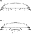
- FIG. 1 shows a rail vehicle roof here a flat roof forming roof panel 1, which is composed of individual, in the longitudinal direction of the rail vehicle (here a single car body) extending aluminum extruded profiles 2, which adjoin one another transverse to the rail vehicle.
- the roof panel 1 is part of a shell of the rail vehicle and is supported laterally on side walls 3.
- On an underside of two of the extruded profiles 2 separate extruded profiles 4 are provided which protrude vertically from the roof panel 1 down, extending in the longitudinal direction of the rail vehicle parallel to each other and are web-shaped. These extruded profiles 4 are integrated in the roof panel 1.
- the webs 4 are already provided in the production of the extruded profiles.
- the webs 4 extend over at least 40%, preferably 50% to 60%, of a total length of a respective car body of the rail vehicle.
- the percentage basically depends on a length ratio between flat roof and high roof areas.
- the webs 4 are arranged mirror-symmetrically with respect to a vertical longitudinal center plane of the rail vehicle. A in the transverse direction of the rail vehicle between the webs 4 extending portion 5 of the roof panel 1 on the underside forms a ceiling of a roof air conditioning duct 6 (see. Fig. 2 ). The webs 4 contrast form side walls of the roof air conditioning channel. 6
- An underside of the roof panel 1 is covered with an insulating layer 7, in particular also the section 5 of the roof panel 1, and is pierced by the webs 4.
- FIG. 2 is now the formation of the roof air conditioning duct 6 completely clear.
- Still open bottom of the roof air conditioning duct 6 is airtight closed by means of an elongated bottom element 8, which is fixed to the lower edges of the webs 4. This happens, for example, via upwardly directed edge-side webs of the floor element, which then overlap with the extruded profiles 4 and are screwed thereto.
- An underside of the floor element 8 is formed by a perforated ceiling 9, so that guided in the roof air conditioning duct 6, conditioned air can pass through the perforated ceiling 9 into a vehicle interior of the rail vehicle.
- roof air conditioning duct 6 insides of the webs 4 are covered with insulating material 10 so that the roof air duct 6 is a total of acoustically isolated in particular.
- the construction of the roof air conditioning duct 8 can then take place in such a way that already the roof plate comprises the webs 4.
- the insulation of the underside of the roof panel 1 and the insides of the webs 4 can be made in one go.
- the bottom element 8 of the roof air conditioning duct 6 and any interfaces in the longitudinal direction of the car body for connection to a compact air conditioner, a silencer or the completion of the roof air conditioning duct 6 are added later, so that the roof air duct 6 is then completely closed.
Landscapes
- Engineering & Computer Science (AREA)
- Mechanical Engineering (AREA)
- Life Sciences & Earth Sciences (AREA)
- Wood Science & Technology (AREA)
- Air-Conditioning For Vehicles (AREA)
- Body Structure For Vehicles (AREA)
Description
- Die Erfindung bezieht sich auf ein Schienenfahrzeug mit einem Dachklimakanal, der unterhalb einer Dachplatte des Schienenfahrzeugs angeordnet ist.
- Bei einem solchen Schienenfahrzeug ist der Dachklimakanal wesentlicher Bestandteil eines Luftverteilsystems für Warm- und Kaltluft. Dabei stellt der Dachklimakanal eine Verbindung zwischen einem häufig auf einem Dach des Schienenfahrzeugs angeordneten Kompaktklimagerät zu Luftauslässen zu einem Fahrgastinnenraum des Schienenfahrzeugs her.
- Zur Ausbildung des Dachklimakanals sind Lösungen bekannt, bei denen er aus festen Materialien, wie Metall, hergestellt und aus in Längsrichtung des Schienenfahrzeugs aneinander anschließenden Kanalsegmenten aufgebaut ist. Diese Variante zur Ausführung des Dachklimakanals wird entlang des Schienenfahrzeugs segmentweise an vorgesehenen Haltern befestigt. Diese Halter sind an einem Rohbau des Schienenfahrzeugs angebracht, beispielsweise an einer Unterseite der Dachplatte. Zusätzlich müssen die Segmente des Dachklimakanals untereinander verbunden und gegenüber dem restlichen Innenraum des Schienenfahrzeugs abgedichtet werden. Die Segmente haben aus Kostengründen und fertigungsbedingt häufig einen rechteckigen Querschnitt und sind zwischen dem Fahrgastinnenraum und dem Dach des Schienenfahrzeugs angeordnet. Die Montage eines solchen Dachklimakanals gestaltet sich somit als sehr aufwendig, da sowohl die einzelnen Dachklimakanal-Segmente untereinander als auch am Schienenfahrzeugrohbau zu befestigen sind. Auch ergibt es sich dadurch, dass sowohl der Fahrzeugrohbau als auch der Dachklimakanal einzeln mit Isolationsmaterial versehen werden. Häufig liegt eine Doppelisolation vor, die an sich nicht notwendig wäre.
- Die Dokumente
DE 197 46 795 A1 ,EP 2 476 599 A1 ,EP 0 990 574 A2 ,DE 10 2009 058 413 A1 ,JP 2001 163217 A JP 2001 163217 A - Ausgehend hiervon liegt der Erfindung die Aufgabe zugrunde, ein Schienenfahrzeug der eingangs genannten Art insofern weiterzuentwickeln, dass sich eine vereinfachte Montage ergibt.
- Diese Aufgabe wird bei dem Schienenfahrzeug durch die kennzeichnenden Merkmale des Anspruchs 1 gelöst.
- Danach ist vorgesehen, dass die Dachplatte aus einzelnen, in Längsrichtung des Schienenfahrzeugs verlaufenden Strangpressprofilen (2) aufgebaut ist, die sich quer zum Schienenfahrzeug aneinander anschließen, in die Dachplatte zwei nach unten vorstehende, sich in Längsrichtung des Schienenfahrzeugs parallel zueinander erstreckende, Stege integriert sind, die an einer Unterseite von zweien der Strangpressprofile vorgesehen sind und wenigstens einen Abschnitt von Seitenwänden des Dachklimakanals bilden, wobei ein sich in Querrichtung des Schienenfahrzeugs zwischen den Stegen erstreckender Abschnitt der Dachplatte eine Decke des Dachklimakanals bildet und der Dachklimakanal ein langgestrecktes Bodenelement aufweist, das an die Stege luftdicht angeschlossen ist.
- Gegenüber dem Stand der Technik verminderter Montageaufwand ergibt sich dadurch, dass wenigstens ein vertikaler Abschnitt der Stege sowie der horizontale Abschnitt der Dachplatte zwischen den Strangpressprofilen bereits drei Seiten eines Dachklimakanals ausbilden. Für eine Vervollständigung des Dachklimakanals ist es nur noch erforderlich, das Bodenelement von unten an die Stege anzusetzen und zu befestigen.
- Die Seitenwände des Dachklimakanals können nur teilweise von den Stegen ausgebildet werden. In diesem Fall kann das Bodenelement auch einen allgemein C-förmigen Querschnitt aufweisen, dessen Schenkel einen unteren Abschnitt der Seitenwände bilden. Es ist jedoch bevorzugt, dass die Stege die Seitenwände des Dachklimakanals vollständig ausbilden. Dann ergibt sich eine einfache herzustellende Form für das zum Verschließen des Dachklimakanals erforderliche langgestreckte Bodenelement.
- Der Dachklimakanal kann beispielsweise auch an einem typischerweise gekrümmten Hochdach eines Schienenfahrzeugs verwirklicht werden. Zur Realisierung eines rechtwinkligen Querschnitts ist es jedoch bevorzugt, wenn die Dachplatte flach ausgebildet ist.
- Das Bodenelement kann an unteren Rändern der stegartigen Strangpressprofile luftdicht angeschlossen sein. Dadurch wird in einfacher Weise eine Vervollständigung des Dachklimakanals herbeigeführt.
- Vorteilhafterweise können die einem Inneren des Dachklimakanals zugewandten Seiten der Stege und des sich zwischen den Stegen erstreckenden Abschnitts der Dachplatte mit Isolationsmaterial belegt sein. In dieser Weise werden Doppelungen bei einer Isolation, die sonst durch eine modulare Bauweise mit gesondertem Dachklimakanal entstehen können, wirksam verhindert.
- Die Stege und damit auch der Dachklimakanal insgesamt erstrecken sich bevorzugt über wenigstens die Hälfte der Länge der Dachplatte des Schienenfahrzeugs. In diesem Fall ergibt sich ein Dachklimakanal, der über eine große Länge gerade und ohne Umlenkungen ist. Dies bringt auch akustische Vorteile durch die Minimierung von Strömungsgeräuschen sowie einen geringen Druckverlust des Dachklimakanals mit sich. Es ergeben sich weniger Schnittstellen im Dachklimakanal als wenn er, wie im Stand der Technik bekannt, aus vielen Segmenten aufgebaut ist. Dies trägt ebenfalls zur Dichtigkeit des Dachklimakanals bei. Die sich daraus ergebende geringere Leckageluftmenge verringert Energieverluste des Luftverteilsystems, zu dem der Dachklimakanal gehört.
- Das Bodenelement kann eine Lochdecke zur Zuführung von Luft in einen Fahrgastinnenraum des Schienenfahrzeugs aufweisen. Dies bewirkt eine günstige Verteilung von beispielsweise klimatisierter Luft aus dem Dachklimakanal in den Fahrgastinnenraum.
- Ein Ausführungsbeispiel der Erfindung wird nachfolgend unter Bezugnahme auf die Zeichnungen noch näher erläutert.
- Es zeigen:
- Figur 1
- eine schematische Querschnittsansicht eines Schienenfahrzeugdaches, das zur Montage eines Dachklimakanals vorbereitet ist, und
- Figur 2
- eine schematische Querschnittsansicht des Schienenfahrzeugdaches von
Figur 1 mit vervollständigtem Dachklimakanal. - Wie aus
Figur 1 hervorgeht, zeigt ein Schienenfahrzeugdach eine hier ein Flachdach ausbildende Dachplatte 1, die aus einzelnen, in Längsrichtung des Schienenfahrzeugs (hier ein einzelner Wagenkasten) verlaufenden Aluminium-Strangpressprofilen 2 aufgebaut ist, die sich quer zum Schienenfahrzeug aneinander anschließen. Die Dachplatte 1 ist Teil eines Rohbaus des Schienenfahrzeugs und stützt sich seitlich auf Seitenwände 3 ab. An einer Unterseite von zweien der Strangpressprofile 2 sind gesonderte Strangpressprofile 4 vorgesehen, die von der Dachplatte 1 aus vertikal nach unten vorstehen, sich in Längsrichtung des Schienenfahrzeugs parallel zueinander erstrecken und stegförmig ausgebildet sind. Diese Strangpressprofile 4 sind in die Dachplatte 1 integriert. Die Stege 4 sind bereits bei der Herstellung der Strangpressprofile vorgesehen. - Die Stege 4 erstrecken sich über wenigstens 40%, bevorzugt 50% bis 60%, einer Gesamtlänge eines betreffenden Wagenkastens des Schienenfahrzeugs. Der Prozentsatz hängt grundsätzlich von einem Längenverhältnis zwischen Flachdach- und Hochdachbereichen ab.
- Die Stege 4 sind spiegelsymmetrisch gegenüber einer vertikalen Längsmittelebene des Schienenfahrzeugs angeordnet. Ein in Querrichtung des Schienenfahrzeugs zwischen den Stegen 4 erstreckender Abschnitt 5 der Dachplatte 1 auf dessen Unterseite bildet eine Decke eines Dachklimakanals 6 (vgl.
Fig. 2 ). Die Stege 4 bilden demgegenüber Seitenwände des Dachklimakanals 6. - Eine Unterseite der Dachplatte 1 ist mit einer Isolationsschicht 7 belegt, insbesondere auch der Abschnitt 5 der Dachplatte 1, und wird durch die Stege 4 durchbrochen.
- Aus
Figur 2 geht nunmehr die Ausbildung des Dachklimakanals 6 vollständig hervor. Die inFigur 1 noch offene Unterseite des Dachklimakanals 6 wird mit Hilfe eines langgestreckten Bodenelements 8 luftdicht geschlossen, das an unteren Rändern der Stege 4 befestigt ist. Dies geschieht beispielsweise über nach oben gerichtete, randseitige Stege des Bodenelements, die dann mit den Strangpressprofilen 4 überlappen und mit diesen verschraubt sind. Eine Unterseite des Bodenelements 8 wird von einer Lochdecke 9 gebildet, so dass im Dachklimakanal 6 geführte, klimatisierte Luft durch die Lochdecke 9 hindurch in einen Fahrzeuginnenraum des Schienenfahrzeugs gelangen kann. - Zur Vervollständigung der Isolation des Dachklimakanals 6 sind Innenseiten der Stege 4 mit Isolationsmaterial 10 belegt, so dass der Dachklimakanal 6 insgesamt insbesondere akustisch isoliert ist.
- Der Aufbau des Dachklimakanals 8 kann dann in der Weise erfolgen, dass bereits die Dachplatte die Stege 4 umfasst. Die Isolierung der Unterseite der Dachplatte 1 und der Innenseiten der Stege 4 kann in einem Zuge vorgenommen werden. Das Bodenelement 8 des Dachklimakanals 6 und etwaige Schnittstellen
in Längsrichtung des Wagenkastens zum Anschluss an ein Kompaktklimagerät, einen Schalldämpfer oder zum Abschluss des Dachklimakanals 6 werden nachträglich hinzugefügt, so dass der Dachklimakanal 6 dann vollständig geschlossen ist.
Claims (6)
- Schienenfahrzeug mit einem Dachklimakanal (6), der unterhalb einer Dachplatte (1) des Schienenfahrzeugs angeordnet ist,
dadurch gekennzeichnet, dass
die Dachplatte (1) aus einzelnen, in Längsrichtung des Schienenfahrzeugs verlaufenden Strangpressprofilen (2) aufgebaut ist, die sich quer zum Schienenfahrzeug aneinander anschlie-βen, in die Dachplatte (1) zwei nach unten vorstehende, sich in Längsrichtung des Schienenfahrzeugs parallel zueinander erstreckende, Stege (4) integriert sind, die an einer Unterseite von zweien der Strangpressprofile (2) vorgesehen sind und wenigstens einen Abschnitt von Seitenwänden des Dachklimakanals (6) bilden, wobei ein sich in Querrichtung des Schienenfahrzeugs zwischen den Stegen (4) erstreckender Abschnitt (5) der Dachplatte (1) eine Decke des Dachklimakanals (6) bildet und der Dachklimakanal (6) ein langgestrecktes Bodenelement (8) aufweist, das an die Stege (4) luftdicht angeschlossen ist. - Schienenfahrzeug nach Anspruch 1,
dadurch gekennzeichnet, dass
die Stege (4) die Seitenwände des Dachklimakanals (6) vollständig ausbilden. - Schienenfahrzeug nach Anspruch 1 oder 2,
dadurch gekennzeichnet, dass
die Dachplatte (1) flach ausgebildet ist. - Schienenfahrzeug nach einem der Ansprüche 1 bis 3,
dadurch gekennzeichnet, dass
das Bodenelement (8) an unteren Rändern der Stege (4) luftdicht angeschlossen ist. - Schienenfahrzeug nach einem der Ansprüche 1 bis 4,
dadurch gekennzeichnet, dass
die einem Inneren des Dachklimakanals (6) zugewandten Seiten der Stege (4) und des sich zwischen den Stegen (4) erstreckenden Abschnitts (5) der Dachplatte (1) mit Isolationsmaterial belegt sind. - Schienenfahrzeug nach einem der Ansprüche 1 bis 5,
dadurch gekennzeichnet, dass
das Bodenelement (8) eine Lochdecke (9) zur Zuführung von Luft in einen Fahrgastinnenraum des Schienenfahrzeugs aufweist.
Applications Claiming Priority (1)
| Application Number | Priority Date | Filing Date | Title |
|---|---|---|---|
| DE102014218442.8A DE102014218442A1 (de) | 2014-09-15 | 2014-09-15 | Schienenfahrzeug mit einem Dachklimakanal |
Publications (2)
| Publication Number | Publication Date |
|---|---|
| EP3002173A1 EP3002173A1 (de) | 2016-04-06 |
| EP3002173B1 true EP3002173B1 (de) | 2019-10-30 |
Family
ID=54065229
Family Applications (1)
| Application Number | Title | Priority Date | Filing Date |
|---|---|---|---|
| EP15183866.1A Active EP3002173B1 (de) | 2014-09-15 | 2015-09-04 | Schienenfahrzeug mit einem dachklimakanal |
Country Status (2)
| Country | Link |
|---|---|
| EP (1) | EP3002173B1 (de) |
| DE (1) | DE102014218442A1 (de) |
Families Citing this family (3)
| Publication number | Priority date | Publication date | Assignee | Title |
|---|---|---|---|---|
| DE102016004314A1 (de) * | 2016-04-12 | 2017-10-12 | Siemens Aktiengesellschaft | Wagenkasten für ein Schienenfahrzeug |
| CN109109885B (zh) * | 2018-08-24 | 2020-02-21 | 中车南京浦镇车辆有限公司 | 轨道车辆车顶内装结构 |
| CN113060170B (zh) * | 2019-12-16 | 2022-06-03 | 中车唐山机车车辆有限公司 | 轨道车辆模块化顶板结构 |
Family Cites Families (7)
| Publication number | Priority date | Publication date | Assignee | Title |
|---|---|---|---|---|
| DE19746795A1 (de) * | 1997-10-23 | 1999-04-29 | Duewag Ag | Innenverkleidung für den Deckenbereich eines großräumigen Fahrzeuges zur Personenbeförderung |
| DE19844812A1 (de) * | 1998-09-30 | 2000-04-13 | Daimler Chrysler Ag | Wagenkasten mit Dachabschlußplatte und Querspriegeln |
| JP3626891B2 (ja) * | 1999-12-06 | 2005-03-09 | 日本車輌製造株式会社 | 鉄道車両用構体 |
| JP3503058B2 (ja) * | 2000-07-27 | 2004-03-02 | 日本車輌製造株式会社 | 鉄道車両の天井構造 |
| DE102009058413B4 (de) * | 2009-12-16 | 2024-11-28 | Siemens Mobility GmbH | Schienenfahrzeug mit einer Innendeckenanordnung |
| JP5643660B2 (ja) * | 2011-01-13 | 2014-12-17 | 株式会社日立製作所 | 鉄道車両 |
| JP5295406B2 (ja) * | 2011-05-11 | 2013-09-18 | 日本車輌製造株式会社 | 鉄道車両の天井構造 |
-
2014
- 2014-09-15 DE DE102014218442.8A patent/DE102014218442A1/de not_active Ceased
-
2015
- 2015-09-04 EP EP15183866.1A patent/EP3002173B1/de active Active
Non-Patent Citations (1)
| Title |
|---|
| None * |
Also Published As
| Publication number | Publication date |
|---|---|
| EP3002173A1 (de) | 2016-04-06 |
| DE102014218442A1 (de) | 2016-03-17 |
Similar Documents
| Publication | Publication Date | Title |
|---|---|---|
| EP0832022A1 (de) | Personenbeförderungsfahrzeug | |
| EP1899207B1 (de) | Luftkanalsystem für fahrzeuge, insbesondere für schienenfahrzeuge des personenverkehrs | |
| DE102010011568A1 (de) | Wagenkasten eines Schienenfahrzeugs und Verfahren zu seiner Herstellung | |
| DE102013002641A1 (de) | Dachvoutenvorrichtung für ein Fahrzeug | |
| DE102012212466A1 (de) | Luftkanalsystem für ein Schienenfahrzeug des Personenverkehrs | |
| EP3705802B1 (de) | Schalldämmanordnung | |
| EP3075580B1 (de) | Doppelbalganordnung für einen übergang zwischen zwei gelenkig miteinander verbundenen fahrzeugteilen eines fahrzeugs, fahrzeug mit einer doppelbalganordnung, verfahren zum herstellen einer doppelbalganordnung, sowie zum herstellen eines fahrzeugs mit einer doppelbalganordnung | |
| EP3002173A1 (de) | Schienenfahrzeug mit einem dachklimakanal | |
| EP2852524A1 (de) | Kabine für eine schwimmende anlage mit leitungen die zur versteifung beitragen | |
| EP2354686B9 (de) | Deckenluftauslass für Zuluft und Induktion von Raumluft in horizontaler Richtung einer klimatechnischen Anlage | |
| EP1832492A2 (de) | Schienenfahrzeug, ausgestattet mit einem Entwässerungssystem für einen Einstiegsbereich | |
| EP2996923B1 (de) | Luftauslass | |
| DE102012204503B4 (de) | Lampenband für einen Fahrgastinnenraum eines Schienenfahrzeugs | |
| EP3085846A1 (de) | Überströmelement und wandelement | |
| DE102016004314A1 (de) | Wagenkasten für ein Schienenfahrzeug | |
| EP2800684B1 (de) | Schienenfahrzeug mit klimakanal im dachbereich und verfahren zum aufbau eines dachbereichs eines schienenfahrzeugs | |
| DE102012108411A1 (de) | Schienenfahrzeug mit einem in einen Gepäckträger teilweise integrierten Lüftungskanal, und Gepäckträgermodul zum Aufbau eines Gepäckträgers | |
| DE102012201000A1 (de) | Bekleidungselement für eine Seitenwand eines Schienenfahrzeugs | |
| DE102014208790A1 (de) | Klimakanal zum Einbau in einen Dachbereich eines Schienenfahrzeugs | |
| DD243249A1 (de) | Innendecke fuer schienenfahrzeuge, insbesondere fuer grossraumpersonenwagen | |
| EP3732404B1 (de) | Verfahren zur herstellung eines segments einer klimakanalanordnung und segment einer klimakanalanordnung | |
| EP2522916A2 (de) | Klimamodul | |
| DE1454580C (de) | ||
| EP4269231A1 (de) | Isolierungsanordnung für ein fahrzeug mit integrierter luftleitung | |
| DE2833169A1 (de) | Zwischenwandung, insbesondere zwischendecke, zwischen fahrgastraum und einem wandungshohlraum, insbesondere deckenhohlraum, eines fahrzeuges, beispielsweise eines eisenbahnwaggons |
Legal Events
| Date | Code | Title | Description |
|---|---|---|---|
| PUAI | Public reference made under article 153(3) epc to a published international application that has entered the european phase |
Free format text: ORIGINAL CODE: 0009012 |
|
| AK | Designated contracting states |
Kind code of ref document: A1 Designated state(s): AL AT BE BG CH CY CZ DE DK EE ES FI FR GB GR HR HU IE IS IT LI LT LU LV MC MK MT NL NO PL PT RO RS SE SI SK SM TR |
|
| AX | Request for extension of the european patent |
Extension state: BA ME |
|
| 17P | Request for examination filed |
Effective date: 20161004 |
|
| RBV | Designated contracting states (corrected) |
Designated state(s): AL AT BE BG CH CY CZ DE DK EE ES FI FR GB GR HR HU IE IS IT LI LT LU LV MC MK MT NL NO PL PT RO RS SE SI SK SM TR |
|
| RAP1 | Party data changed (applicant data changed or rights of an application transferred) |
Owner name: SIEMENS AKTIENGESELLSCHAFT |
|
| RAP1 | Party data changed (applicant data changed or rights of an application transferred) |
Owner name: SIEMENS MOBILITY GMBH |
|
| RIC1 | Information provided on ipc code assigned before grant |
Ipc: B61D 17/12 20060101AFI20190325BHEP Ipc: B61D 27/00 20060101ALI20190325BHEP |
|
| GRAP | Despatch of communication of intention to grant a patent |
Free format text: ORIGINAL CODE: EPIDOSNIGR1 |
|
| STAA | Information on the status of an ep patent application or granted ep patent |
Free format text: STATUS: GRANT OF PATENT IS INTENDED |
|
| INTG | Intention to grant announced |
Effective date: 20190521 |
|
| GRAS | Grant fee paid |
Free format text: ORIGINAL CODE: EPIDOSNIGR3 |
|
| GRAA | (expected) grant |
Free format text: ORIGINAL CODE: 0009210 |
|
| STAA | Information on the status of an ep patent application or granted ep patent |
Free format text: STATUS: THE PATENT HAS BEEN GRANTED |
|
| AK | Designated contracting states |
Kind code of ref document: B1 Designated state(s): AL AT BE BG CH CY CZ DE DK EE ES FI FR GB GR HR HU IE IS IT LI LT LU LV MC MK MT NL NO PL PT RO RS SE SI SK SM TR |
|
| REG | Reference to a national code |
Ref country code: GB Ref legal event code: FG4D Free format text: NOT ENGLISH |
|
| REG | Reference to a national code |
Ref country code: CH Ref legal event code: EP |
|
| REG | Reference to a national code |
Ref country code: AT Ref legal event code: REF Ref document number: 1195822 Country of ref document: AT Kind code of ref document: T Effective date: 20191115 |
|
| REG | Reference to a national code |
Ref country code: DE Ref legal event code: R096 Ref document number: 502015010779 Country of ref document: DE |
|
| REG | Reference to a national code |
Ref country code: IE Ref legal event code: FG4D Free format text: LANGUAGE OF EP DOCUMENT: GERMAN |
|
| REG | Reference to a national code |
Ref country code: CH Ref legal event code: NV Representative=s name: SIEMENS SCHWEIZ AG, CH |
|
| REG | Reference to a national code |
Ref country code: LT Ref legal event code: MG4D |
|
| PG25 | Lapsed in a contracting state [announced via postgrant information from national office to epo] |
Ref country code: FI Free format text: LAPSE BECAUSE OF FAILURE TO SUBMIT A TRANSLATION OF THE DESCRIPTION OR TO PAY THE FEE WITHIN THE PRESCRIBED TIME-LIMIT Effective date: 20191030 Ref country code: BG Free format text: LAPSE BECAUSE OF FAILURE TO SUBMIT A TRANSLATION OF THE DESCRIPTION OR TO PAY THE FEE WITHIN THE PRESCRIBED TIME-LIMIT Effective date: 20200130 Ref country code: GR Free format text: LAPSE BECAUSE OF FAILURE TO SUBMIT A TRANSLATION OF THE DESCRIPTION OR TO PAY THE FEE WITHIN THE PRESCRIBED TIME-LIMIT Effective date: 20200131 Ref country code: LV Free format text: LAPSE BECAUSE OF FAILURE TO SUBMIT A TRANSLATION OF THE DESCRIPTION OR TO PAY THE FEE WITHIN THE PRESCRIBED TIME-LIMIT Effective date: 20191030 Ref country code: NO Free format text: LAPSE BECAUSE OF FAILURE TO SUBMIT A TRANSLATION OF THE DESCRIPTION OR TO PAY THE FEE WITHIN THE PRESCRIBED TIME-LIMIT Effective date: 20200130 Ref country code: NL Free format text: LAPSE BECAUSE OF FAILURE TO SUBMIT A TRANSLATION OF THE DESCRIPTION OR TO PAY THE FEE WITHIN THE PRESCRIBED TIME-LIMIT Effective date: 20191030 Ref country code: SE Free format text: LAPSE BECAUSE OF FAILURE TO SUBMIT A TRANSLATION OF THE DESCRIPTION OR TO PAY THE FEE WITHIN THE PRESCRIBED TIME-LIMIT Effective date: 20191030 Ref country code: PL Free format text: LAPSE BECAUSE OF FAILURE TO SUBMIT A TRANSLATION OF THE DESCRIPTION OR TO PAY THE FEE WITHIN THE PRESCRIBED TIME-LIMIT Effective date: 20191030 Ref country code: ES Free format text: LAPSE BECAUSE OF FAILURE TO SUBMIT A TRANSLATION OF THE DESCRIPTION OR TO PAY THE FEE WITHIN THE PRESCRIBED TIME-LIMIT Effective date: 20191030 Ref country code: LT Free format text: LAPSE BECAUSE OF FAILURE TO SUBMIT A TRANSLATION OF THE DESCRIPTION OR TO PAY THE FEE WITHIN THE PRESCRIBED TIME-LIMIT Effective date: 20191030 Ref country code: PT Free format text: LAPSE BECAUSE OF FAILURE TO SUBMIT A TRANSLATION OF THE DESCRIPTION OR TO PAY THE FEE WITHIN THE PRESCRIBED TIME-LIMIT Effective date: 20200302 |
|
| REG | Reference to a national code |
Ref country code: NL Ref legal event code: MP Effective date: 20191030 |
|
| PG25 | Lapsed in a contracting state [announced via postgrant information from national office to epo] |
Ref country code: RS Free format text: LAPSE BECAUSE OF FAILURE TO SUBMIT A TRANSLATION OF THE DESCRIPTION OR TO PAY THE FEE WITHIN THE PRESCRIBED TIME-LIMIT Effective date: 20191030 Ref country code: IS Free format text: LAPSE BECAUSE OF FAILURE TO SUBMIT A TRANSLATION OF THE DESCRIPTION OR TO PAY THE FEE WITHIN THE PRESCRIBED TIME-LIMIT Effective date: 20200229 Ref country code: HR Free format text: LAPSE BECAUSE OF FAILURE TO SUBMIT A TRANSLATION OF THE DESCRIPTION OR TO PAY THE FEE WITHIN THE PRESCRIBED TIME-LIMIT Effective date: 20191030 |
|
| PG25 | Lapsed in a contracting state [announced via postgrant information from national office to epo] |
Ref country code: AL Free format text: LAPSE BECAUSE OF FAILURE TO SUBMIT A TRANSLATION OF THE DESCRIPTION OR TO PAY THE FEE WITHIN THE PRESCRIBED TIME-LIMIT Effective date: 20191030 |
|
| PG25 | Lapsed in a contracting state [announced via postgrant information from national office to epo] |
Ref country code: EE Free format text: LAPSE BECAUSE OF FAILURE TO SUBMIT A TRANSLATION OF THE DESCRIPTION OR TO PAY THE FEE WITHIN THE PRESCRIBED TIME-LIMIT Effective date: 20191030 Ref country code: DK Free format text: LAPSE BECAUSE OF FAILURE TO SUBMIT A TRANSLATION OF THE DESCRIPTION OR TO PAY THE FEE WITHIN THE PRESCRIBED TIME-LIMIT Effective date: 20191030 Ref country code: CZ Free format text: LAPSE BECAUSE OF FAILURE TO SUBMIT A TRANSLATION OF THE DESCRIPTION OR TO PAY THE FEE WITHIN THE PRESCRIBED TIME-LIMIT Effective date: 20191030 Ref country code: RO Free format text: LAPSE BECAUSE OF FAILURE TO SUBMIT A TRANSLATION OF THE DESCRIPTION OR TO PAY THE FEE WITHIN THE PRESCRIBED TIME-LIMIT Effective date: 20191030 |
|
| REG | Reference to a national code |
Ref country code: DE Ref legal event code: R097 Ref document number: 502015010779 Country of ref document: DE |
|
| PG25 | Lapsed in a contracting state [announced via postgrant information from national office to epo] |
Ref country code: SM Free format text: LAPSE BECAUSE OF FAILURE TO SUBMIT A TRANSLATION OF THE DESCRIPTION OR TO PAY THE FEE WITHIN THE PRESCRIBED TIME-LIMIT Effective date: 20191030 Ref country code: IT Free format text: LAPSE BECAUSE OF FAILURE TO SUBMIT A TRANSLATION OF THE DESCRIPTION OR TO PAY THE FEE WITHIN THE PRESCRIBED TIME-LIMIT Effective date: 20191030 Ref country code: SK Free format text: LAPSE BECAUSE OF FAILURE TO SUBMIT A TRANSLATION OF THE DESCRIPTION OR TO PAY THE FEE WITHIN THE PRESCRIBED TIME-LIMIT Effective date: 20191030 |
|
| PLBE | No opposition filed within time limit |
Free format text: ORIGINAL CODE: 0009261 |
|
| STAA | Information on the status of an ep patent application or granted ep patent |
Free format text: STATUS: NO OPPOSITION FILED WITHIN TIME LIMIT |
|
| 26N | No opposition filed |
Effective date: 20200731 |
|
| PG25 | Lapsed in a contracting state [announced via postgrant information from national office to epo] |
Ref country code: SI Free format text: LAPSE BECAUSE OF FAILURE TO SUBMIT A TRANSLATION OF THE DESCRIPTION OR TO PAY THE FEE WITHIN THE PRESCRIBED TIME-LIMIT Effective date: 20191030 |
|
| PG25 | Lapsed in a contracting state [announced via postgrant information from national office to epo] |
Ref country code: MC Free format text: LAPSE BECAUSE OF FAILURE TO SUBMIT A TRANSLATION OF THE DESCRIPTION OR TO PAY THE FEE WITHIN THE PRESCRIBED TIME-LIMIT Effective date: 20191030 |
|
| REG | Reference to a national code |
Ref country code: BE Ref legal event code: MM Effective date: 20200930 |
|
| PG25 | Lapsed in a contracting state [announced via postgrant information from national office to epo] |
Ref country code: LU Free format text: LAPSE BECAUSE OF NON-PAYMENT OF DUE FEES Effective date: 20200904 |
|
| PG25 | Lapsed in a contracting state [announced via postgrant information from national office to epo] |
Ref country code: IE Free format text: LAPSE BECAUSE OF NON-PAYMENT OF DUE FEES Effective date: 20200904 Ref country code: BE Free format text: LAPSE BECAUSE OF NON-PAYMENT OF DUE FEES Effective date: 20200930 |
|
| PG25 | Lapsed in a contracting state [announced via postgrant information from national office to epo] |
Ref country code: MT Free format text: LAPSE BECAUSE OF FAILURE TO SUBMIT A TRANSLATION OF THE DESCRIPTION OR TO PAY THE FEE WITHIN THE PRESCRIBED TIME-LIMIT Effective date: 20191030 Ref country code: CY Free format text: LAPSE BECAUSE OF FAILURE TO SUBMIT A TRANSLATION OF THE DESCRIPTION OR TO PAY THE FEE WITHIN THE PRESCRIBED TIME-LIMIT Effective date: 20191030 |
|
| PG25 | Lapsed in a contracting state [announced via postgrant information from national office to epo] |
Ref country code: MK Free format text: LAPSE BECAUSE OF FAILURE TO SUBMIT A TRANSLATION OF THE DESCRIPTION OR TO PAY THE FEE WITHIN THE PRESCRIBED TIME-LIMIT Effective date: 20191030 |
|
| PG25 | Lapsed in a contracting state [announced via postgrant information from national office to epo] |
Ref country code: TR Free format text: LAPSE BECAUSE OF NON-PAYMENT OF DUE FEES Effective date: 20200904 |
|
| PGFP | Annual fee paid to national office [announced via postgrant information from national office to epo] |
Ref country code: FR Payment date: 20240916 Year of fee payment: 10 |
|
| PGFP | Annual fee paid to national office [announced via postgrant information from national office to epo] |
Ref country code: AT Payment date: 20240809 Year of fee payment: 10 |
|
| PGFP | Annual fee paid to national office [announced via postgrant information from national office to epo] |
Ref country code: DE Payment date: 20241118 Year of fee payment: 10 |
|
| PGFP | Annual fee paid to national office [announced via postgrant information from national office to epo] |
Ref country code: GB Payment date: 20241007 Year of fee payment: 10 |
|
| PGFP | Annual fee paid to national office [announced via postgrant information from national office to epo] |
Ref country code: CH Payment date: 20241203 Year of fee payment: 10 |
|
| REG | Reference to a national code |
Ref country code: DE Ref legal event code: R119 Ref document number: 502015010779 Country of ref document: DE |
|
| REG | Reference to a national code |
Ref country code: CH Ref legal event code: H13 Free format text: ST27 STATUS EVENT CODE: U-0-0-H10-H13 (AS PROVIDED BY THE NATIONAL OFFICE) Effective date: 20260504 |
|
| REG | Reference to a national code |
Ref country code: AT Ref legal event code: MM01 Ref document number: 1195822 Country of ref document: AT Kind code of ref document: T Effective date: 20250904 |
|
| GBPC | Gb: european patent ceased through non-payment of renewal fee |
Effective date: 20250904 |
|
| PG25 | Lapsed in a contracting state [announced via postgrant information from national office to epo] |
Ref country code: GB Free format text: LAPSE BECAUSE OF NON-PAYMENT OF DUE FEES Effective date: 20250904 |
|
| PG25 | Lapsed in a contracting state [announced via postgrant information from national office to epo] |
Ref country code: DE Free format text: LAPSE BECAUSE OF NON-PAYMENT OF DUE FEES Effective date: 20260401 |
|
| PG25 | Lapsed in a contracting state [announced via postgrant information from national office to epo] |
Ref country code: AT Free format text: LAPSE BECAUSE OF NON-PAYMENT OF DUE FEES Effective date: 20250904 |
|
| PG25 | Lapsed in a contracting state [announced via postgrant information from national office to epo] |
Ref country code: CH Free format text: LAPSE BECAUSE OF NON-PAYMENT OF DUE FEES Effective date: 20250930 |
|
| PG25 | Lapsed in a contracting state [announced via postgrant information from national office to epo] |
Ref country code: FR Free format text: LAPSE BECAUSE OF NON-PAYMENT OF DUE FEES Effective date: 20250930 |