EP3001479A1 - Organic light-emitting display device - Google Patents
Organic light-emitting display device Download PDFInfo
- Publication number
- EP3001479A1 EP3001479A1 EP15187299.1A EP15187299A EP3001479A1 EP 3001479 A1 EP3001479 A1 EP 3001479A1 EP 15187299 A EP15187299 A EP 15187299A EP 3001479 A1 EP3001479 A1 EP 3001479A1
- Authority
- EP
- European Patent Office
- Prior art keywords
- layer
- buffer layer
- organic light
- area
- display device
- Prior art date
- Legal status (The legal status is an assumption and is not a legal conclusion. Google has not performed a legal analysis and makes no representation as to the accuracy of the status listed.)
- Granted
Links
- 239000000758 substrate Substances 0.000 claims abstract description 143
- 238000005538 encapsulation Methods 0.000 claims abstract description 83
- 239000002245 particle Substances 0.000 claims abstract description 60
- 239000010410 layer Substances 0.000 claims description 327
- 239000012790 adhesive layer Substances 0.000 claims description 48
- 239000000463 material Substances 0.000 claims description 28
- 239000010409 thin film Substances 0.000 claims description 21
- 239000000126 substance Substances 0.000 claims description 8
- 238000000034 method Methods 0.000 description 21
- 230000008569 process Effects 0.000 description 20
- QVGXLLKOCUKJST-UHFFFAOYSA-N atomic oxygen Chemical compound [O] QVGXLLKOCUKJST-UHFFFAOYSA-N 0.000 description 9
- 229910052760 oxygen Inorganic materials 0.000 description 9
- 239000001301 oxygen Substances 0.000 description 9
- VYPSYNLAJGMNEJ-UHFFFAOYSA-N Silicium dioxide Chemical compound O=[Si]=O VYPSYNLAJGMNEJ-UHFFFAOYSA-N 0.000 description 6
- 229910052814 silicon oxide Inorganic materials 0.000 description 6
- 230000007547 defect Effects 0.000 description 5
- 239000011229 interlayer Substances 0.000 description 5
- 229920001187 thermosetting polymer Polymers 0.000 description 5
- 239000004642 Polyimide Substances 0.000 description 4
- 230000008901 benefit Effects 0.000 description 4
- 238000004519 manufacturing process Methods 0.000 description 4
- 239000012466 permeate Substances 0.000 description 4
- 229920001721 polyimide Polymers 0.000 description 4
- 229920005989 resin Polymers 0.000 description 4
- 239000011347 resin Substances 0.000 description 4
- 229910052581 Si3N4 Inorganic materials 0.000 description 3
- 229910004205 SiNX Inorganic materials 0.000 description 3
- 239000000853 adhesive Substances 0.000 description 3
- 230000001070 adhesive effect Effects 0.000 description 3
- 239000010408 film Substances 0.000 description 3
- 230000003287 optical effect Effects 0.000 description 3
- 230000035939 shock Effects 0.000 description 3
- HQVNEWCFYHHQES-UHFFFAOYSA-N silicon nitride Chemical compound N12[Si]34N5[Si]62N3[Si]51N64 HQVNEWCFYHHQES-UHFFFAOYSA-N 0.000 description 3
- 238000005520 cutting process Methods 0.000 description 2
- 230000002542 deteriorative effect Effects 0.000 description 2
- 230000001681 protective effect Effects 0.000 description 2
- 229920006344 thermoplastic copolyester Polymers 0.000 description 2
- 229910016909 AlxOy Inorganic materials 0.000 description 1
- XUIMIQQOPSSXEZ-UHFFFAOYSA-N Silicon Chemical compound [Si] XUIMIQQOPSSXEZ-UHFFFAOYSA-N 0.000 description 1
- -1 acryl Chemical group 0.000 description 1
- 238000005452 bending Methods 0.000 description 1
- 239000003086 colorant Substances 0.000 description 1
- 229920001577 copolymer Polymers 0.000 description 1
- 230000032798 delamination Effects 0.000 description 1
- 238000005137 deposition process Methods 0.000 description 1
- 230000000694 effects Effects 0.000 description 1
- 238000005516 engineering process Methods 0.000 description 1
- 239000003822 epoxy resin Substances 0.000 description 1
- 229920002457 flexible plastic Polymers 0.000 description 1
- 230000009969 flowable effect Effects 0.000 description 1
- 238000005187 foaming Methods 0.000 description 1
- 239000011521 glass Substances 0.000 description 1
- 230000003993 interaction Effects 0.000 description 1
- 238000003698 laser cutting Methods 0.000 description 1
- 239000007788 liquid Substances 0.000 description 1
- 239000004973 liquid crystal related substance Substances 0.000 description 1
- 239000002184 metal Substances 0.000 description 1
- 229910052751 metal Inorganic materials 0.000 description 1
- 238000012986 modification Methods 0.000 description 1
- 230000004048 modification Effects 0.000 description 1
- 239000012044 organic layer Substances 0.000 description 1
- 230000001151 other effect Effects 0.000 description 1
- TWNQGVIAIRXVLR-UHFFFAOYSA-N oxo(oxoalumanyloxy)alumane Chemical compound O=[Al]O[Al]=O TWNQGVIAIRXVLR-UHFFFAOYSA-N 0.000 description 1
- 238000002161 passivation Methods 0.000 description 1
- 229920000515 polycarbonate Polymers 0.000 description 1
- 239000004417 polycarbonate Substances 0.000 description 1
- 229920000647 polyepoxide Polymers 0.000 description 1
- 239000000047 product Substances 0.000 description 1
- 230000004044 response Effects 0.000 description 1
- 239000004065 semiconductor Substances 0.000 description 1
- 238000000926 separation method Methods 0.000 description 1
- 229910052710 silicon Inorganic materials 0.000 description 1
- 239000010703 silicon Substances 0.000 description 1
Images


Classifications
-
- H—ELECTRICITY
- H10—SEMICONDUCTOR DEVICES; ELECTRIC SOLID-STATE DEVICES NOT OTHERWISE PROVIDED FOR
- H10K—ORGANIC ELECTRIC SOLID-STATE DEVICES
- H10K50/00—Organic light-emitting devices
- H10K50/80—Constructional details
- H10K50/84—Passivation; Containers; Encapsulations
- H10K50/842—Containers
- H10K50/8426—Peripheral sealing arrangements, e.g. adhesives, sealants
-
- H—ELECTRICITY
- H10—SEMICONDUCTOR DEVICES; ELECTRIC SOLID-STATE DEVICES NOT OTHERWISE PROVIDED FOR
- H10K—ORGANIC ELECTRIC SOLID-STATE DEVICES
- H10K50/00—Organic light-emitting devices
- H10K50/80—Constructional details
- H10K50/84—Passivation; Containers; Encapsulations
- H10K50/844—Encapsulations
-
- H—ELECTRICITY
- H10—SEMICONDUCTOR DEVICES; ELECTRIC SOLID-STATE DEVICES NOT OTHERWISE PROVIDED FOR
- H10K—ORGANIC ELECTRIC SOLID-STATE DEVICES
- H10K59/00—Integrated devices, or assemblies of multiple devices, comprising at least one organic light-emitting element covered by group H10K50/00
- H10K59/10—OLED displays
- H10K59/12—Active-matrix OLED [AMOLED] displays
- H10K59/122—Pixel-defining structures or layers, e.g. banks
-
- H—ELECTRICITY
- H10—SEMICONDUCTOR DEVICES; ELECTRIC SOLID-STATE DEVICES NOT OTHERWISE PROVIDED FOR
- H10K—ORGANIC ELECTRIC SOLID-STATE DEVICES
- H10K59/00—Integrated devices, or assemblies of multiple devices, comprising at least one organic light-emitting element covered by group H10K50/00
- H10K59/10—OLED displays
- H10K59/12—Active-matrix OLED [AMOLED] displays
- H10K59/123—Connection of the pixel electrodes to the thin film transistors [TFT]
-
- H—ELECTRICITY
- H10—SEMICONDUCTOR DEVICES; ELECTRIC SOLID-STATE DEVICES NOT OTHERWISE PROVIDED FOR
- H10K—ORGANIC ELECTRIC SOLID-STATE DEVICES
- H10K2102/00—Constructional details relating to the organic devices covered by this subclass
-
- H—ELECTRICITY
- H10—SEMICONDUCTOR DEVICES; ELECTRIC SOLID-STATE DEVICES NOT OTHERWISE PROVIDED FOR
- H10K—ORGANIC ELECTRIC SOLID-STATE DEVICES
- H10K2102/00—Constructional details relating to the organic devices covered by this subclass
- H10K2102/301—Details of OLEDs
- H10K2102/302—Details of OLEDs of OLED structures
- H10K2102/3023—Direction of light emission
- H10K2102/3026—Top emission
-
- H—ELECTRICITY
- H10—SEMICONDUCTOR DEVICES; ELECTRIC SOLID-STATE DEVICES NOT OTHERWISE PROVIDED FOR
- H10K—ORGANIC ELECTRIC SOLID-STATE DEVICES
- H10K2102/00—Constructional details relating to the organic devices covered by this subclass
- H10K2102/301—Details of OLEDs
- H10K2102/351—Thickness
-
- H—ELECTRICITY
- H10—SEMICONDUCTOR DEVICES; ELECTRIC SOLID-STATE DEVICES NOT OTHERWISE PROVIDED FOR
- H10K—ORGANIC ELECTRIC SOLID-STATE DEVICES
- H10K71/00—Manufacture or treatment specially adapted for the organic devices covered by this subclass
- H10K71/851—Division of substrate
Definitions
- the present disclosure relates to an organic light-emitting display (OLED) device, and more particularly to an OLED device with improved production yields and reliability by eliminating the possibility that a portion of an adhesive layer used for attaching an upper substrate to a lower substrate is not attached on the substrates in a bezel area.
- OLED organic light-emitting display
- An organic light-emitting display device is capable of producing light on its own and thus does not require an additional light source, as in a liquid crystal display device (LCD). Therefore, an OLED device can be made lighter and thinner. Further, an OLED device has advantages in that it is driven with low voltage to consume less power and realizes better colors. Also, an OLED device has a fast response time, a wide viewing angle and a high contrast ratio (CR). For these reasons, an OLED device is currently under development as the next generation display device.
- FIG. 1 a schematic cross-sectional view of a plurality of OLED devices disposed between mother substrates in the related art.
- FIG. 1 shows a first OLED device PA1 and a second OLED device PA2 when a lower mother substrate 190 is attached to an upper mother substrate 195.
- two OLED devices PA1 and PA2 are defined on the lower mother substrate 190 in FIG. 1 for convenience of illustration, the number of the OLED devices defined on the lower mother substrate 190 is not limited to two.
- an OLED device is manufactured in such a manner that a plurality of thin-film transistors 120, a plurality of organic light-emitting elements 140, etc. are disposed between the lower mother substrate 190 and the upper mother substrate 195.
- the lower mother substrate 190 is attached to the upper mother substrate 195, and then the mother substrates are divided into individual organic light-emitting devices.
- the plurality of thin-film transistors 120 are disposed in a display area DA of the lower mother substrate 190.
- a gate insulating layer 131, an interlayer insulating layer 132 and a planarization layer 133 are disposed in the display area DA during the manufacturing process of disposing the thin-film transistor 120.
- the plurality of organic light-emitting elements 140 are disposed on the planarization layer 133.
- a bank layer 134 is disposed around the plurality of organic light-emitting elements 140.
- a bezel area BA a variety of lines 160 and/or circuitry necessary for driving the display area DA may be disposed.
- ends of the planarization layer 133 and the bank layer 134 have a tapered shape.
- there is a step difference between the bezel area BA and the display area DA which is approximately equal to the sum of the thickness of the planarization layer 133 and the thickness of the bank layer 134.
- an encapsulation layer 135 for protecting the organic light-emitting element 140 from moisture and oxygen is disposed on the organic light-emitting element 140.
- the position of a cut line CUT along which one OLED device is separated from another is determined between adjacent bezel areas BAs.
- a buffer region is disposed closely to the cut line CUT in the bezel area BA. The buffer region is configured to absorb physical impacts, such as shocks or vibrations, generated when the cut line CUT is cut by a cutter or a laser. Therefore, no conductive lines or circuitry are disposed in the buffer region.
- the upper mother substrate 195 is attached to the lower mother substrate 190 by an adhesive layer 170.
- the adhesive layer 170 may not be sufficiently filled up in the unwanted space or may not be securely attached to the upper mother substrate 195 and/or the lower mother substrate 190 at the boundary between the bezel area BA of the first OLED device PA1 and the bezel area BA of the second OLED device PA2.
- a space S where the adhesive layer is not properly attached on the substrates may be created in the bezel areas BA as shown in FIG. 1 .
- cracks or damage may occur during other processes of cutting the set of mother substrates into individual OLED devices, such as a process of laser cutting or a process of mechanical scribing, in which strong energy is exerted on the upper mother substrate 195. Therefore, crack may still occur in the lines 160 or other components.
- an additional process may be performed after the set of mother substrates has been cut into individual OLED devices.
- a process of attaching a polarizing plate or a process of applying a protective film onto the upper substrate or the lower substrate using a roller may be performed.
- cracks may occur in the lines 160 or insulating layers due to generated pressure.
- pressure is exerted on the lower substrate during a process of attaching a polarizing plate, whereby cracks may occur in the lines 160 or the insulating layers. Accordingly, cracks occur in the line 160 or the insulating layers due to the space S created in the bezel area BA, deteriorating the production yields and reliability of an OLED device.
- the adhesive layer 170 and the lower substrate may peel off or otherwise not be attached properly, and the lower substrate may not be securely attached to the upper substrate. Therefore, delamination or process failure may be caused during subsequent processes.
- moisture or oxygen may permeate through the space S from a side surface of an OLED device, deteriorating the lifespan and reliability of the OLED device.
- the inventors of the present disclosure have devised an OLED device having a novel structure for solving the above-described problems associated with the OLED devices according to the related art.
- an object of the present disclosure is to provide an OLED device capable of minimizing a space where an adhesive layer is not attached on a substrate due to a step difference of an encapsulation layer.
- Another object of the present disclosure is to provide an OLED device capable of reducing cracks occurring in lines during a process of attaching an upper substrate to a lower substrate and suppressing a substrate from being peeled off, by minimizing a space where an adhesive layer is not attached on a substrate.
- an organic light-emitting display (OLED) device comprising: a display area including a thin-film transistor and an organic light-emitting element on a lower substrate; a bezel area configured to surround the display area; a transparent encapsulation unit including at least a first encapsulation layer, a first particle cover layer and a second encapsulation layer; and a first buffer layer, wherein the first encapsulation layer, on the organic light-emitting element, covers the display area and the bezel area, wherein the first particle cover layer, on the first encapsulation layer, covers the display area and at least a portion of the bezel area adjacent to the display area, wherein the first buffer layer, apart from the first particle cover layer, on the first encapsulation layer, covers at least another portion of the bezel area, wherein the second encapsulation layer, which covers the first particle cover layer and the first buffer layer, is in contact with the first encapsulation layer at a contact surface between the first particle
- an element A on an element B refers to that the element A may be disposed directly on the element B and/or the element A may be disposed indirectly on the element B via another element C.
- first, second, third and the like in the descriptions and in the claims are used for distinguishing between similar elements and not necessarily for describing a sequential or chronological order. These terms are used to merely distinguish one element from another. Accordingly, as used herein, a first element may be a second element within the technical idea of the present disclosure.
- FIG. 2 is a schematic plan view for illustrating areas on a lower substrate of an OLED device according to an exemplary embodiment of the present disclosure.
- FIG. 3 is a schematic cross-sectional view of the OLED device according to an exemplary embodiment of the present disclosure, taken along the line III - III' of FIG. 2.
- FIGS. 2 and 3 show an OLED device 200 after attaching an upper mother substrate to a lower mother substrate to cut them along a cut line CUT. All the components of the OLED devices according to the embodiments of the present invention are operatively coupled and configured.
- the OLED device 200 includes a lower substrate 210, a thin-film transistor 220, an organic light-emitting element 240, a transparent encapsulation unit 235, an adhesive layer 270 and an upper substrate 215.
- a thin-film transistor 220 and one organic light-emitting element 240 will be described for convenience of illustration. However, more than one thin-film transistor and more than one organic light-emitting element 240 may be employed.
- the OLED device 200 is of a top emission type in which light generated from the organic light-emitting layer 240 is emitted via the upper substrate 215.
- FIG. 3 shows only one sub-pixel region in a display area DA for the sake of simplicity.
- the lower substrate 210 supports thereon a variety of elements of the OLED device 200.
- the lower substrate 210 is made of an insulative material that is suitable for being subjected to semiconductor deposition processes and supporting the thin-film transistor 220 and the organic light-emitting element 240 disposed on the lower substrate 210.
- the lower substrate 210 may be made of a material having flexibility, e.g., flexible plastic, glass, polyimide, and the like.
- the back plate 218 acts as a protective film.
- the lower substrate 210 of the OLED device 200 includes a display area DA, a bezel area BA and a pad area TA.
- the display area DA refers to an area of the OLED device 200 where an image is displayed.
- the bezel area BA refers to an area of the OLED device 200 where no image is displayed and lines 260 and/or circuitry are disposed.
- the bezel area BA surrounds the display area DA.
- the pad area TA refers to an area of the OLED device 200 where a pad unit is disposed.
- An integrated circuit may be disposed in the pad area TA or a flexible printed circuit board may be connected to the pad area TA.
- the pad area TA may be disposed on a side of the bezel area BA.
- a thin-film transistor 220 is disposed, which includes an active layer 221, a gate electrode 222, a source electrode 223 and a drain electrode 224.
- the active layer 221 is formed on the lower substrate 210.
- a gate insulating layer 231 for insulating the active layer 221 from the electrode 222 is formed on the active layer 221.
- the gate electrode 222 is formed on the gate insulating layer 231 above the active layer 221.
- An interlayer insulating layer 232 is formed over the gate electrode 222 and the gate insulating layer 231.
- the source electrode 223 and the drain electrode 224 are formed on the interlayer insulating layer 232.
- the source electrode 223 and the drain electrode 224 are electrically connected to the active layer 221.
- the thin-film transistor 220 has a coplanar structure herein, an inverted staggered thin-film transistor may also be used.
- additional multi-buffer layers may be disposed between the lower substrate 210 and the thin-film transistor 220.
- the multi-buffer layers may be four layers formed by alternately stacking silicon nitride SiN x and silicon oxide SiO x .
- a planarization layer 233 is disposed on the thin-film transistor 220.
- the planarization layer 233 planarizes the area above the thin-film transistor 220.
- the planarization layer 233 includes a contact hole for electrically connecting the thin-film transistor 220 to the anode 241 of the organic light-emitting element 240.
- lens-like features may be patterned on a portion of the planarization layer 233 where the anode 241 is disposed.
- the organic light-emitting element 240 is disposed on the planarization layer 233.
- the organic light-emitting element 240 includes the anode 241 formed on the planarization layer 233 to be electrically connected to the thin-film transistor 220, an organic light-emitting layer 242 formed on the anode 241, and a cathode 243 formed on the organic light-emitting layer 242.
- the anode 241 may include a reflective layer 244 for reflecting light generated from the organic light-emitting layer 242 toward the upper substrate 215 and a transparent conductive layer 245 for injecting holes into the organic light-emitting layer 242.
- the anode 241 includes the reflective layer 244 in FIG. 3
- the anode 241 may include the transparent conductive layer 245 only and the reflective layer 244 may be formed separated from the anode 241.
- the organic light-emitting layer 242 is an organic layer for emitting light of a particular color and may be one of red, green, blue and white organic light-emitting layer.
- the organic light-emitting layer 242 may be formed on the entire display area DA of the lower substrate 210, which is the case of the white organic light-emitting layer 242.
- the thickness of the organic light-emitting element 240 is exaggerated in FIG. 3 for the sake of clarity, the organic light-emitting element 240 is actually much thinner than the adhesive layer 270. That is, the thickness as illustrated in the figures is merely for describing the features of the present disclosure and the present disclosure is not limited by the figures.
- a color filter or color refiner may be formed above the organic light-emitting element 240.
- a bank layer 234 is disposed over the anode 241 and the passivation layer 233.
- the bank layer 234 defines a sub-pixel region by separating adjacent sub-pixel regions in the display area DA.
- the bank layer 234 may define a pixel region including a plurality of sub-pixel regions.
- the bank layer 234 is extended from the display area DA to a portion of the bezel area BA.
- the conductive lines 260 are disposed in the bezel area BA of the lower substrate 210.
- the lines 260 are electrically connected to the thin-film transistor 220 or the organic light-emitting element 240 formed in the display area DA to deliver signals.
- the lines 260 may be made of the same material as one of various conductive elements formed in the display area DA.
- the lines 250 may be made of, but is not limited to, the same material as the source electrode 223, the gate electrode 222 and/or the anode 241 as shown in FIG. 3 .
- a gate electrode driving unit may be formed that is made of the same material as the source electrode 223 and the gate electrode 222 to apply a driving signal to the gate electrode 222.
- a connecting unit 265 that is made of the same material as the anode 241 and applies ground voltage VSS to the cathode 243 may be formed to be connected to a ground voltage line 261.
- the gate insulating layer 231, the interlayer insulating layer 232, the planarization layer 233 and the bank layer 234 are all formed in the bezel area BA. However, some of the gate insulating layer 231, the interlayer insulating layer 232, the planarization layer 233 and the bank layer 234 may be selectively formed in the bezel BA.
- the transparent encapsulation unit 235 is disposed in the display area DA and the bezel area BA.
- the transparent encapsulation unit 235 is configured to transmit light generated from the organic light-emitting element 240.
- the transparent encapsulation unit 235 at least includes a transparent first encapsulation layer 235a, a transparent first particle cover layer 235b, and a transparent second encapsulation layer 235c. Furthermore, it is possible to include an additional transparent third encapsulation layer, an additional transparent second particle cover layer, and an additional transparent fourth encapsulation layer on the transparent encapsulation unit 235. But it is not limited thereto. Use of such additional layers depends upon the product to be manufactured and the desired encapsulation and/or particle coverage to be achieved.
- the first encapsulation layer 235a and the second encapsulation layer 235c of the transparent encapsulation unit 235 can be made of a transparent inorganic substance.
- the transparent inorganic substance may include silicon nitride (SiN x ), silicon oxide (SiO x ), aluminum oxide (Al x O y ), etc.
- the first particle cover layer 235b of the transparent encapsulation unit 235 can be made of a flowable, transparent organic substance.
- the transparent organic substance may include an epoxy resin, an acryl resin, silicon oxycarbide (SiOC), etc.
- the first particle cover layer 235b is disposed between the first encapsulation layer 235a and the second encapsulation layer 235c.
- the first particle cover layer 235b can fill cracks caused by foreign matter generated between the first encapsulation layer 235a and the second encapsulation layer 235c.
- cracks caused by foreign matter in the first encapsulation layer 235a or the second encapsulation layer 235c may result in defects in the transparent encapsulation unit 235.
- the first particle cover layer fills the cracks to reduce defects in the transparent encapsulation unit 235.
- a first buffer layer 235d for reducing step difference which is made of the same material as the first particle cover layer 235b, is disposed in the bezel area BA adjacent to a cut line CUT.
- the first buffer layer 235d is configured to reduce an area between the upper substrate 215 and the lower substrate 215 at the bezel area BA such that the adhesive layer 270 fills up the reduced area at the bezel area BA. That is, the first buffer layer 235d is configured to reduce a gap difference of the display area DA and the bezel area BA.
- the first buffer layer 235d is configured to absorb shocks, impacts, vibrations, etc.
- the first buffer layer 235d is configured to help maintain a cell gap between the lower substrate 210 and the upper substrate 215. By forming the first buffer layer 235d, the space where the adhesive layer is not attached on the substrate in the bezel area BA can be reduced. Accordingly, with this configuration, the problem relating to the poor attachment can be improved.
- the first encapsulation layer 235a and the second encapsulation layer 235c of the transparent encapsulation unit 235 seal the first particle cover layer 235b in the bezel area BA. Since the first particle cover layer 235b cannot effectively suppress moisture permeation, moisture and oxygen may permeate through the first particle cover layer 235b to result in defects in the organic light-emitting element 240. With the configuration according to an exemplary embodiment of the present disclosure, the first particle cover layer 235b is sealed by the first encapsulation layer 235 and the second encapsulation layer 235, so that the moisture and oxygen permeation path via the first particle cover layer 132 can be eliminated.
- the first encapsulation layer 235a comes in direct contact with the second encapsulation layer 235c between the first particle cover layer 235b and the first buffer layer 235d, so that the make the first particle cover layer 235b is separated from the first buffer layer 235d.
- the first particle cover layer 235b is spaced apart from the first buffer layer 235d by a predetermined distance.
- the buffer layer 235d cannot effectively suppress moisture permeation, and thus moisture and oxygen may permeate through the buffer layer 235d.
- the first particle cover layer 235b and the buffer layer 235d are separated and spaced apart from each other by the first encapsulation layer 235a and the second encapsulation layer 235c, the first particle cover layer 235b is sealed. Accordingly, moisture permeation path from the first buffer layer 235d to the first particle cover layer 235b can be eliminated.
- the space where the adhesive layer is not attached on the substrate is reduced so that the problem relating to the poor attachment is solved, and the path via which moisture and oxygen permeate from the first buffer layer 235d to the first particle cover layer 235b can be eliminated or at least significantly minimized.
- the width W of a contact surface where the first encapsulation layer 235a meets the second encapsulation layer is determined depending on the distance by which the first buffer layer 235d is spaced apart from the first particle cover layer 235b.
- the width W of the contact surface where the first particle cover layer 235b meets the buffer layer 235d is for example, at least 50 ⁇ m. If the width W of the contact surface is less than 50 ⁇ m, the first particle cover layer 235b and the first buffer layer 235d may be connected to each other to result in defects.
- the width W of the contact surface of the first encapsulation layer 235a and the second encapsulation layer 235c is equal to or less than 200 ⁇ m. If the width W of the contact surface is greater than 200 ⁇ m, a space with a step difference becomes larger, so that the problem relating to the poor attachment cannot be effectively solved.
- the width W of the contact surface where the first encapsulation layer 235a meets the second encapsulation layer 235c may be between 50 ⁇ m and 200 ⁇ m, but not limited thereto.
- the first buffer layer 235d can be formed together with the first particle cover layer 235 in the same process by simply modifying the mask for foaming the first particle cover layer 235, without an additional process.
- the OLED device 200 includes the display area DA including the thin-film transistor 220 and the organic light-emitting element 240 formed on the lower substrate 210 and the bezel area BA surrounding the display area DA.
- the first encapsulation layer 235a is formed on the organic light-emitting element 240 such that it covers the display area DA and the bezel area BA.
- the first particle cover layer 235b covers the display area DA and at least a portion of the bezel area BA adjacent to the display area DA.
- the first buffer layer 235d covering at least another portion of the bezel area BA is formed on the first encapsulation layer 235a.
- the second encapsulation layer 235c covering the display area DA and the bezel area BA is formed.
- the first particle cover layer 235b is spaced apart from the first buffer layer 235d by a certain distance.
- the first encapsulation layer 235a and the second encapsulation layer 235c may come in contact with each other at the contact surface where the first particle cover layer 235b is spaced apart from the first buffer layer 235d by a predetermined distance, to thereby reduce the area of a space where the adhesive layer is not attached on the substrate.
- the adhesive layer 270 is made of an adhesive material for attaching the upper substrate 215 to the lower substrate 210. Specifically, the adhesive layer 270 supports the transparent encapsulation layer 235 disposed on the upper substrate 215 and the lower substrate 210. The adhesive layer 270 may seal the organic light-emitting element 240 formed on the lower substrate 210 to protect the organic light-emitting element 240 from moisture and oxygen coming from outside the OLED device 200. That is, the adhesive layer 270 is configured to sufficiently fill the space between the transparent encapsulation unit 235 and the upper substrate 215 in the display area DA and the bezel area BA.
- the adhesive layer 270 may be made of a variety of materials such as an optical clear adhesive (OCA) film, a liquid optical clear resin (OCR), etc. or combinations thereof.
- OCA optical clear adhesive
- OCR liquid optical clear resin
- the adhesive material may have thermosetting or pressure-sensitive properties.
- the adhesive layer 270 of the OLED device 200 has a particular thermosetting property.
- the thermosetting property provides an advantage in that the adhesive layer 270 can flow well for a time period while it is cured under high temperature, so that it can effectively fill the area in the bezel area BA over the buffer layer 235d.
- the adhesive layer 270 can have a thickness ofless than 20 ⁇ m.
- the first buffer layer 235d is disposed in the bezel area BA to suppress the space where the adhesive layer is not attached on the substrate, even with the adhesive layer 270 with a thickness of less than 20 ⁇ m.
- the upper substrate 215 is disposed to face the lower substrate 210 and supports thereon a variety of elements of the OLED device 200.
- the upper substrate 215 may be made of a flexible material and may be made of the same material as the lower substrate 210.
- the lower substrate 210 includes the display area DA and the bezel area BA herein, the upper substrate 215 may also have a display area and a bezel area similarly to the lower substrate 210.
- the upper substrate 215 may be made of one of copolyester thermoplastic elastomer (COP), cycoolefin copolymer (COC) and polycarbonate (PC) which can suppress moisture permeation via the front surface of the display area DA.
- COP copolyester thermoplastic elastomer
- COC cycoolefin copolymer
- PC polycarbonate
- the upper substrate 215 has optically isotropic properties for improving image quality of the display area DA.
- the upper substrate 215 may be made of the same material as the lower substrate 210. If the upper substrate 215 is made of polyimide, multi-buffer layers may be further disposed between the upper substrate 215 and the adhesive layer 270.
- the multi-buffer layers may be four layers formed by alternately stacking silicon nitride SiNx and silicon oxide SiOx. Such buffer layers are necessary because polyimide cannot effectively suppress moisture permeation, although it is suitable for forming various insulating layers and metal lines. Accordingly, an additional element for suppressing moisture permeation via the front surface, such as multi-buffer layers, is necessary. Additionally, if the upper substrate 215 is made of polyimide, a touch sensor, a temperature sensor, an optical sensor, etc., may be disposed on the upper substrate 215.
- FIG. 4 is a schematic cross-sectional view of an OLED device according to another exemplary embodiment of the present disclosure.
- the bezel area BA of the OLED device 400 includes a first buffer layer for reducing step difference 235d and a second buffer layer for reducing step difference 435.
- the second buffer layer 435 is disposed under the first encapsulation layer 235a. Further, the first buffer layer 235d is on the second buffer layer 435. With this configuration, the space where the adhesive layer is not attached on the substrate in the bezel area BA can be reduced by the first buffer layer 235d and the second buffer layer 435.
- the second buffer layer 435 is configured to further reduce the area between the upper substrate 215 and the lower substrate 210 at the bezel area BA.
- the second buffer layer for reducing step difference 435 of the OLED device 400 is made of the same material as a bank layer 234. Accordingly, the second buffer layer 435 can be formed together with the bank layer 234 in the same process by simply changing the mask, without requiring an additional process. In some embodiments, the second buffer layer 435 may be made of the same material as the planarization layer 233, and may be formed together with the planarization layer 233 in the same process by simply changing the mask, without requiring an additional process.
- the second buffer layer 435 has a flat surface and has a larger width than the first buffer layer 235d. As the second buffer layer 435 is wider than the first buffer layer 235d, the first buffer layer 235d does not easily flow down along the tapered shape of the second buffer layer 435. In particular, if the adhesive layer 270 is made of a thermosetting resin which flows well, it is desirable to make the surface on which the first buffer layer 235d is formed flat.
- the other elements of the OLED device 400 are or can be substantially identical to those of the OLED device 200; and, therefore, will not be described to avoid redundancy.
- FIG. 5 is a schematic cross-sectional view of an OLED device according to the other exemplary embodiment of the present disclosure.
- a first buffer layer for reducing step difference 235d in a bezel area BA of an OLED device 500, a first buffer layer for reducing step difference 235d, a second buffer layer for reducing step difference 435 and a third buffer layer for reducing step difference 535 are disposed.
- the second buffer layer 435 is disposed on the third buffer layer 535.
- the first buffer 235d and the second buffer layer 435 are on the third buffer layer 535.
- the space where the adhesive layer is not attached on the substrate in the bezel area BA can be further reduced by the first buffer layer 235d, the second buffer layer 435 and the third buffer layer 535.
- the third buffer layer 535 for reducing step difference of the OLED device 500 according to the other exemplary embodiment of the present disclosure is made of the same material as the planarization layer 233.
- the second buffer layer 435 is made of the same material as the bank layer 234. Accordingly, the second buffer layer 435 and the third buffer layer 535 can be formed together with the planarization layer 233 and the bank layer 234, respectively, in the same processes by simply changing the masks, without requiring an additional process.
- the third buffer layer 535 may have a larger width than that of the second buffer layer 435. As the third buffer layer 535 is wider than the second buffer layer 435, the first buffer layer 235d does not easily flow down along the tapered shape of the third buffer layer 535.
- the other elements of the OLED device 500 are or can be substantially identical to those of the OLED device 400 described above; and, therefore, will not be described to avoid redundancy.
- FIG. 6 is a cross-sectional view of an OLED device according to another exemplary embodiment of the present disclosure.
- a first buffer layer for reducing step difference 635 is formed on a second encapsulation layer 235c.
- the first buffer layer for reducing step difference 635 of the OLED device 600 is made of the same material as the first particle cover layer 235b.
- the adhesive layer 270 made of a thermosetting resin or a pressure-sensitive material can be used.
- the thickness of the adhesive layer 270 may be less than 5 ⁇ m.
- the other elements of the OLED device 600 are or can be substantially identical to those of the OLED device 400 described above; and, therefore, will not be described to avoid redundancy.
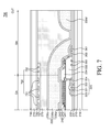
- FIG. 7 is a cross-sectional view of an OLED device according to another exemplary embodiment of the present disclosure.
- a touch sensing unit 750 is disposed on an upper substrate 215 of an OLED device 700.
- Multi-buffer layers 736 are disposed under the upper substrate 215.
- the multi-buffer layers 736 act as layers for protecting the touch sensing unit 750 and the organic light-emitting element 240 from the moisture and oxygen permeating via the upper substrate 215.
- the multi-buffer layers 736 are formed in the display area DA and the bezel area BA under the upper substrate 215.
- the touch sensing unit 750 is disposed under the upper substrate 215. Specifically, the touch sensing unit 750 is disposed on the bottom surface of the multi-buffer layers 736 under the upper substrate 215.
- the touch sensing unit 750 includes touch sensing electrodes 751 disposed in the display area DA and touch lines 752 disposed in the bezel area BA.
- the touch lines 752 deliver touch sensing signals from the touch sensing electrodes 751.
- the touch sensing unit 750 may be formed below the upper substrate 215 as shown in FIG. 7 . In that case, in the OLED device 700 according to another exemplary embodiment of the present disclosure, an in-cell type touch screen panel can be implemented.
- An overcoat layer 737 may be disposed under the touch sensing unit 750.
- the overcoat layer 737 planarizes the area below the touch sensing unit 750 and is formed in the display area DA and the bezel area BA between the upper substrate 215 and the adhesive layer 270.
- the overcoat layer 737 may be made of the same material as the planarization layer 233.
- a polarizing plate 738 is disposed on the top surface of the upper substrate 215.
- the polarizing plate 738 is an element for minimizing reflections of external light by reflective material of the OLED device 700 and may be disposed on the top surface of the upper substrate 215.
- the polarizing plate 738 is an optional element and thus may not be included in the OLED 700. Instead of the polarizing plate 738, another element for reducing reflections of external light may be included in the OLED device 700 or one of existing elements of the OLED device 700 may be altered.
- the other elements of the OLED device 700 are or can be substantially identical to those of the OLED device 200 described above; and, therefore, will not be described to avoid redundancy.
- An organic light-emitting display device comprises a display area including a thin-film transistor and an organic light-emitting element on a lower substrate; a bezel area configured to surround the display area; a transparent encapsulation unit including at least a first encapsulation layer, a first particle cover layer and a second encapsulation layer; and a first buffer layer, wherein the first encapsulation layer, on the organic light-emitting element, covers the display area and the bezel area, wherein the first particle cover layer, on the first encapsulation layer, covers the display area and at least a portion of the bezel area adjacent to the display area, wherein the first buffer layer, apart from the first particle cover layer, on the first encapsulation layer, covers at least another portion of the bezel area, wherein the second encapsulation layer, which covers the first particle cover layer and the first buffer layer, is in contact with the first encapsulation layer at a contact surface between the first particle cover layer and the first buffer layer.
- a width of the contact surface may be determined by a distance between the first buffer layer and the first particle cover layer.
- the width of the contact surface may be equal to or less than 200 ⁇ m.
- the width of the contact surface may be equal to or greater than 50 ⁇ m.
- the organic light-emitting display device may further comprise an upper substrate facing the lower substrate and an adhesive layer between the lower substrate and the upper substrate, wherein the first buffer layer is configured to reduce an area between the upper substrate and the lower substrate at the bezel area such that the adhesive layer fills up the reduced area at the bezel area.
- the first buffer layer may be made of the same material as the first particle cover layer.
- the first buffer layer may be configured to absorb physical impacts generated when the lower substrate and the upper substrate are cut.
- the organic light-emitting display device may further comprise a second buffer layer under the first buffer layer and configured to further reduce the area between the upper substrate and the lower substrate at the bezel area, and the second buffer layer may be made of a same material as a bank layer,.
- the second buffer layer may have a flat top surface.
- the first buffer layer may be overlapped with the second buffer layer and a width of the second buffer layer may be wider than a width of the first buffer layer.
- the organic light-emitting display device may further comprise a third buffer layer under the second buffer layer, and the third buffer layer may be made of a same material as a planarization layer and may be configured to further reduce the area between the upper substrate and the lower substrate at the bezel area.
- the second buffer layer may be overlapped with the third buffer layer and a width of the third buffer layer may be wider than the width of the second buffer layer.
- the first encapsulation layer and the second encapsulation layer may be made of an inorganic substance and the first particle cover layer and the first buffer layer may be made of an organic substance.
- the organic light-emitting display device may further comprise an upper substrate facing the lower substrate, and the organic light-emitting display device may be a top emission type in which light generated in the organic light-emitting element is emitted via the upper substrate.
- a thickness of the adhesive layer may be equal to or less than 20 ⁇ m.
Abstract
Description
- This application claims the priority of Korean Patent Application No.
10-2014-0130103 filed on September 29, 2014 - The present disclosure relates to an organic light-emitting display (OLED) device, and more particularly to an OLED device with improved production yields and reliability by eliminating the possibility that a portion of an adhesive layer used for attaching an upper substrate to a lower substrate is not attached on the substrates in a bezel area.
- An organic light-emitting display device (OLED) is capable of producing light on its own and thus does not require an additional light source, as in a liquid crystal display device (LCD). Therefore, an OLED device can be made lighter and thinner. Further, an OLED device has advantages in that it is driven with low voltage to consume less power and realizes better colors. Also, an OLED device has a fast response time, a wide viewing angle and a high contrast ratio (CR). For these reasons, an OLED device is currently under development as the next generation display device.
-
FIG. 1 a schematic cross-sectional view of a plurality of OLED devices disposed between mother substrates in the related art.FIG. 1 shows a first OLED device PA1 and a second OLED device PA2 when alower mother substrate 190 is attached to anupper mother substrate 195. Although two OLED devices (PA1 and PA2) are defined on thelower mother substrate 190 inFIG. 1 for convenience of illustration, the number of the OLED devices defined on thelower mother substrate 190 is not limited to two. - In the related art, an OLED device is manufactured in such a manner that a plurality of thin-
film transistors 120, a plurality of organic light-emitting elements 140, etc. are disposed between thelower mother substrate 190 and theupper mother substrate 195. Thelower mother substrate 190 is attached to theupper mother substrate 195, and then the mother substrates are divided into individual organic light-emitting devices. - Referring to
FIG. 1 , the plurality of thin-film transistors 120 are disposed in a display area DA of thelower mother substrate 190. Agate insulating layer 131, an interlayer insulating layer 132 and aplanarization layer 133 are disposed in the display area DA during the manufacturing process of disposing the thin-film transistor 120. - The plurality of organic light-emitting elements 140 are disposed on the
planarization layer 133. Abank layer 134 is disposed around the plurality of organic light-emitting elements 140. In a bezel area BA, a variety oflines 160 and/or circuitry necessary for driving the display area DA may be disposed. In the bezel area BA, ends of theplanarization layer 133 and thebank layer 134 have a tapered shape. Further, there is a step difference between the bezel area BA and the display area DA, which is approximately equal to the sum of the thickness of theplanarization layer 133 and the thickness of thebank layer 134. - In addition, an encapsulation layer 135 for protecting the organic light-emitting element 140 from moisture and oxygen is disposed on the organic light-emitting element 140. When a plurality of OLED devices are manufactured simultaneously by using a set of mother substrates, the position of a cut line CUT along which one OLED device is separated from another is determined between adjacent bezel areas BAs. In addition, a buffer region is disposed closely to the cut line CUT in the bezel area BA. The buffer region is configured to absorb physical impacts, such as shocks or vibrations, generated when the cut line CUT is cut by a cutter or a laser. Therefore, no conductive lines or circuitry are disposed in the buffer region.
- The
upper mother substrate 195 is attached to thelower mother substrate 190 by anadhesive layer 170. However, in the bezel area BA of each of the first OLED device PA1 and the second OLED device PA2, there exists an unwanted space due to the step difference. Accordingly, theadhesive layer 170 may not be sufficiently filled up in the unwanted space or may not be securely attached to theupper mother substrate 195 and/or thelower mother substrate 190 at the boundary between the bezel area BA of the first OLED device PA1 and the bezel area BA of the second OLED device PA2. As a result, a space S where the adhesive layer is not properly attached on the substrates may be created in the bezel areas BA as shown inFIG. 1 . - Due to the space S (which is an unwanted space) created in the bezel areas BA when the
upper mother substrate 195 is attached to thelower mother substrate 190, pressure applied to the cut line CUT may result in bending or vibrations on theupper mother substrate 195 and thelower mother substrate 190. Shocks or physical impact may occur at this time and may be delivered to theconductive lines 160 and/or the circuitry disposed in the bezel area BA. If such impacts are applied to the bezel area BA, cracks or other types of damage may occur in various components including a variety of lines and insulating layers. Once cracks or damage occur in one component, it can very easily lead to cracks or damage in other components. Even if no cracks occur during the process of attaching theadhesive layer 170, cracks or damage may occur during other processes of cutting the set of mother substrates into individual OLED devices, such as a process of laser cutting or a process of mechanical scribing, in which strong energy is exerted on theupper mother substrate 195. Therefore, crack may still occur in thelines 160 or other components. - In addition, in the existing manufacturing process of an OLED device according to the related art, an additional process may be performed after the set of mother substrates has been cut into individual OLED devices. For example, a process of attaching a polarizing plate or a process of applying a protective film onto the upper substrate or the lower substrate using a roller may be performed. During such processes, cracks may occur in the
lines 160 or insulating layers due to generated pressure. In addition, pressure is exerted on the lower substrate during a process of attaching a polarizing plate, whereby cracks may occur in thelines 160 or the insulating layers. Accordingly, cracks occur in theline 160 or the insulating layers due to the space S created in the bezel area BA, deteriorating the production yields and reliability of an OLED device. - As described above, in the OLED device according to the related art, there exists the space S where the
adhesive layer 170 is not attached on the lower substrate. Accordingly, theadhesive layer 170 and the lower substrate may peel off or otherwise not be attached properly, and the lower substrate may not be securely attached to the upper substrate. Therefore, delamination or process failure may be caused during subsequent processes. In addition, moisture or oxygen may permeate through the space S from a side surface of an OLED device, deteriorating the lifespan and reliability of the OLED device. - The inventors of the present disclosure have devised an OLED device having a novel structure for solving the above-described problems associated with the OLED devices according to the related art.
- In view of the above, an object of the present disclosure is to provide an OLED device capable of minimizing a space where an adhesive layer is not attached on a substrate due to a step difference of an encapsulation layer.
- Another object of the present disclosure is to provide an OLED device capable of reducing cracks occurring in lines during a process of attaching an upper substrate to a lower substrate and suppressing a substrate from being peeled off, by minimizing a space where an adhesive layer is not attached on a substrate.
- It should be noted that objects of the present disclosure are not limited to the above-described object, and other objects of the present disclosure will be apparent to those skilled in the art from the following descriptions.
- According to an aspect of the present disclosure, there is provided an organic light-emitting display (OLED) device comprising: a display area including a thin-film transistor and an organic light-emitting element on a lower substrate; a bezel area configured to surround the display area; a transparent encapsulation unit including at least a first encapsulation layer, a first particle cover layer and a second encapsulation layer; and a first buffer layer, wherein the first encapsulation layer, on the organic light-emitting element, covers the display area and the bezel area, wherein the first particle cover layer, on the first encapsulation layer, covers the display area and at least a portion of the bezel area adjacent to the display area, wherein the first buffer layer, apart from the first particle cover layer, on the first encapsulation layer, covers at least another portion of the bezel area, wherein the second encapsulation layer, which covers the first particle cover layer and the first buffer layer, is in contact with the first encapsulation layer at a contact surface between the first particle cover layer and the first buffer layer.
- It should be noted that effects of the present disclosure are not limited to those described above and other effects of the present disclosure will be apparent to those skilled in the art from the following descriptions.
- The above and other aspects, features and other advantages of the present disclosure will be more clearly understood from the following detailed description taken in conjunction with the accompanying drawings, in which:
-
FIG. 1 a schematic cross-sectional view of a plurality of OLED devices disposed between mother substrates in the related art. -
FIG. 2 is a schematic plan view for illustrating areas on a low substrate of an OLED device according to an exemplary embodiment of the present invention; -
FIG. 3 is a schematic cross-sectional view of the OLED device according to an exemplary embodiment of the present invention, taken along line III - III' ofFIG. 2 ; -
FIG. 4 is a schematic cross-sectional plan view of an OLED device according to another exemplary embodiment of the present invention; -
FIG. 5 is a schematic cross-sectional plan view of an OLED device according to another exemplary embodiment of the present invention; -
FIG. 6 is a schematic cross-sectional plan view of an OLED device according to another exemplary embodiment of the present invention; and -
FIG. 7 is a schematic cross-sectional plan view of an OLED device according to another exemplary embodiment of the present invention. - Advantages and features of the present disclosure and methods to achieve them will become apparent from the descriptions of exemplary embodiments herein below with reference to the accompanying drawings. However, the present disclosure is not limited to exemplary embodiments disclosed herein but may be implemented in various different ways. The exemplary embodiments are provided for making the disclosure of the present disclosure thorough and for fully conveying the scope of the present disclosure to those skilled in the art. It is to be noted that the scope of the present disclosure is defined only by the claims.
- The figures, dimensions, ratios, angles, numbers of elements given in the drawings are merely illustrative and are not limiting. Like reference numerals denote like elements throughout the descriptions. Further, in describing the present disclosure, descriptions on well-known technologies may be omitted in order not to obscure the gist of the present disclosure. It is to be noticed that the terms "comprising," "having," "including" and so on, used in the description and claims, should not be interpreted as being restricted to the means listed thereafter unless specifically stated otherwise. Where an indefinite or definite article is used when referring to a singular noun, e.g. "a," "an," "the," this includes a plural of that noun unless specifically stated otherwise.
- In describing elements, they are interpreted as including error margins even without explicit statements.
- In describing positional relationship, such as "an element A on an element B," "an element A above an element B," "an element A below an element B;" and "an element A next to an element B," another element C may be disposed between the elements A and B unless the term "directly" or "immediately" is explicitly used.
- As used herein, a phrase "an element A on an element B" refers to that the element A may be disposed directly on the element B and/or the element A may be disposed indirectly on the element B via another element C.
- The terms first, second, third and the like in the descriptions and in the claims are used for distinguishing between similar elements and not necessarily for describing a sequential or chronological order. These terms are used to merely distinguish one element from another. Accordingly, as used herein, a first element may be a second element within the technical idea of the present disclosure.
- Like reference numerals denote like elements throughout the descriptions.
- The drawings are not to scale and the relative dimensions of various elements in the drawings are depicted schematically and not necessarily to scale.
- Features of various exemplary embodiments of the present disclosure may be combined partially or totally. As will be clearly appreciated by those skilled in the art, technically various interactions and operations are possible. Various exemplary embodiments can be practiced individually or in combination.
- Hereinafter, exemplary embodiments of the present disclosure will be described in detail with reference to the accompanying drawings.
-
FIG. 2 is a schematic plan view for illustrating areas on a lower substrate of an OLED device according to an exemplary embodiment of the present disclosure.FIG. 3 is a schematic cross-sectional view of the OLED device according to an exemplary embodiment of the present disclosure, taken along the line III - III' ofFIG. 2. FIGS. 2 and3 show anOLED device 200 after attaching an upper mother substrate to a lower mother substrate to cut them along a cut line CUT. All the components of the OLED devices according to the embodiments of the present invention are operatively coupled and configured. - Referring to
FIGS. 2 and3 , theOLED device 200 includes alower substrate 210, a thin-film transistor 220, an organic light-emittingelement 240, atransparent encapsulation unit 235, anadhesive layer 270 and anupper substrate 215. In the following descriptions, one thin-film transistor 220 and one organic light-emittingelement 240 will be described for convenience of illustration. However, more than one thin-film transistor and more than one organic light-emittingelement 240 may be employed. - The
OLED device 200 according to an exemplary embodiment of the present disclosure is of a top emission type in which light generated from the organic light-emittinglayer 240 is emitted via theupper substrate 215.FIG. 3 shows only one sub-pixel region in a display area DA for the sake of simplicity. - The
lower substrate 210 supports thereon a variety of elements of theOLED device 200. Thelower substrate 210 is made of an insulative material that is suitable for being subjected to semiconductor deposition processes and supporting the thin-film transistor 220 and the organic light-emittingelement 240 disposed on thelower substrate 210. Specifically, thelower substrate 210 may be made of a material having flexibility, e.g., flexible plastic, glass, polyimide, and the like. - For the
lower substrate 210 made of a material having flexibility, it is desirable to dispose aback plate 218 for supporting thelower substrate 210. Theback plate 218 acts as a protective film. - Referring to
FIG. 2 , thelower substrate 210 of theOLED device 200 includes a display area DA, a bezel area BA and a pad area TA. The display area DA refers to an area of theOLED device 200 where an image is displayed. The bezel area BA refers to an area of theOLED device 200 where no image is displayed andlines 260 and/or circuitry are disposed. The bezel area BA surrounds the display area DA. The pad area TA refers to an area of theOLED device 200 where a pad unit is disposed. An integrated circuit may be disposed in the pad area TA or a flexible printed circuit board may be connected to the pad area TA. The pad area TA may be disposed on a side of the bezel area BA. - Referring to
FIG. 3 , in the display area DA of thelower substrate 210, a thin-film transistor 220 is disposed, which includes anactive layer 221, agate electrode 222, asource electrode 223 and adrain electrode 224. Specifically, theactive layer 221 is formed on thelower substrate 210. Agate insulating layer 231 for insulating theactive layer 221 from theelectrode 222 is formed on theactive layer 221. Thegate electrode 222 is formed on thegate insulating layer 231 above theactive layer 221. An interlayer insulatinglayer 232 is formed over thegate electrode 222 and thegate insulating layer 231. Thesource electrode 223 and thedrain electrode 224 are formed on theinterlayer insulating layer 232. Thesource electrode 223 and thedrain electrode 224 are electrically connected to theactive layer 221. Herein, for convenience of illustration, only one of thin-film transistors of theOLED device 200 is illustrated, which is connected to theanode 241. In addition, although the thin-film transistor 220 has a coplanar structure herein, an inverted staggered thin-film transistor may also be used. Further, additional multi-buffer layers may be disposed between thelower substrate 210 and the thin-film transistor 220. The multi-buffer layers may be four layers formed by alternately stacking silicon nitride SiNx and silicon oxide SiOx. - A
planarization layer 233 is disposed on the thin-film transistor 220. Theplanarization layer 233 planarizes the area above the thin-film transistor 220. Theplanarization layer 233 includes a contact hole for electrically connecting the thin-film transistor 220 to theanode 241 of the organic light-emittingelement 240. To amplify the luminous intensity, lens-like features may be patterned on a portion of theplanarization layer 233 where theanode 241 is disposed. - The organic light-emitting
element 240 is disposed on theplanarization layer 233. The organic light-emittingelement 240 includes theanode 241 formed on theplanarization layer 233 to be electrically connected to the thin-film transistor 220, an organic light-emittinglayer 242 formed on theanode 241, and acathode 243 formed on the organic light-emittinglayer 242. Since theOLED device 200 is of a top emission type, theanode 241 may include a reflective layer 244 for reflecting light generated from the organic light-emittinglayer 242 toward theupper substrate 215 and a transparent conductive layer 245 for injecting holes into the organic light-emittinglayer 242. Although theanode 241 includes the reflective layer 244 inFIG. 3 , theanode 241 may include the transparent conductive layer 245 only and the reflective layer 244 may be formed separated from theanode 241. - The organic light-emitting
layer 242 is an organic layer for emitting light of a particular color and may be one of red, green, blue and white organic light-emitting layer. The organic light-emittinglayer 242 may be formed on the entire display area DA of thelower substrate 210, which is the case of the white organic light-emittinglayer 242. Although the thickness of the organic light-emittingelement 240 is exaggerated inFIG. 3 for the sake of clarity, the organic light-emittingelement 240 is actually much thinner than theadhesive layer 270. That is, the thickness as illustrated in the figures is merely for describing the features of the present disclosure and the present disclosure is not limited by the figures. In some embodiments, for the white organic light-emittinglayer 242, a color filter or color refiner may be formed above the organic light-emittingelement 240. - A
bank layer 234 is disposed over theanode 241 and thepassivation layer 233. Thebank layer 234 defines a sub-pixel region by separating adjacent sub-pixel regions in the display area DA. In addition, thebank layer 234 may define a pixel region including a plurality of sub-pixel regions. Thebank layer 234 is extended from the display area DA to a portion of the bezel area BA. - The
conductive lines 260 are disposed in the bezel area BA of thelower substrate 210. Thelines 260 are electrically connected to the thin-film transistor 220 or the organic light-emittingelement 240 formed in the display area DA to deliver signals. Thelines 260 may be made of the same material as one of various conductive elements formed in the display area DA. The lines 250 may be made of, but is not limited to, the same material as thesource electrode 223, thegate electrode 222 and/or theanode 241 as shown inFIG. 3 . For example, in the bezel area BA, a gate electrode driving unit may be formed that is made of the same material as thesource electrode 223 and thegate electrode 222 to apply a driving signal to thegate electrode 222. In addition, on theplanarization layer 233 above the gate electrode driving unit, a connectingunit 265 that is made of the same material as theanode 241 and applies ground voltage VSS to thecathode 243 may be formed to be connected to aground voltage line 261. - In
FIG. 3 , thegate insulating layer 231, theinterlayer insulating layer 232, theplanarization layer 233 and thebank layer 234 are all formed in the bezel area BA. However, some of thegate insulating layer 231, theinterlayer insulating layer 232, theplanarization layer 233 and thebank layer 234 may be selectively formed in the bezel BA. - In order to protect the organic light-emitting
element 240 in the display area DA from moisture and oxygen, thetransparent encapsulation unit 235 is disposed in the display area DA and the bezel area BA. In addition, thetransparent encapsulation unit 235 is configured to transmit light generated from the organic light-emittingelement 240. - Referring to
FIG. 3 , thetransparent encapsulation unit 235 at least includes a transparentfirst encapsulation layer 235a, a transparent firstparticle cover layer 235b, and a transparentsecond encapsulation layer 235c. Furthermore, it is possible to include an additional transparent third encapsulation layer, an additional transparent second particle cover layer, and an additional transparent fourth encapsulation layer on thetransparent encapsulation unit 235. But it is not limited thereto. Use of such additional layers depends upon the product to be manufactured and the desired encapsulation and/or particle coverage to be achieved. - The
first encapsulation layer 235a and thesecond encapsulation layer 235c of thetransparent encapsulation unit 235 can be made of a transparent inorganic substance. For example, the transparent inorganic substance may include silicon nitride (SiNx), silicon oxide (SiOx), aluminum oxide (AlxOy), etc. - The first
particle cover layer 235b of thetransparent encapsulation unit 235 can be made of a flowable, transparent organic substance. For example, the transparent organic substance may include an epoxy resin, an acryl resin, silicon oxycarbide (SiOC), etc. - The first
particle cover layer 235b is disposed between thefirst encapsulation layer 235a and thesecond encapsulation layer 235c. The firstparticle cover layer 235b can fill cracks caused by foreign matter generated between thefirst encapsulation layer 235a and thesecond encapsulation layer 235c. In particular, cracks caused by foreign matter in thefirst encapsulation layer 235a or thesecond encapsulation layer 235c may result in defects in thetransparent encapsulation unit 235. The first particle cover layer fills the cracks to reduce defects in thetransparent encapsulation unit 235. - Referring to
FIG. 3 again, in order to solve or address the problem relating to the poor attachment discussed above with respect toFIG. 1 , afirst buffer layer 235d for reducing step difference, which is made of the same material as the firstparticle cover layer 235b, is disposed in the bezel area BA adjacent to a cut line CUT. Thefirst buffer layer 235d is configured to reduce an area between theupper substrate 215 and thelower substrate 215 at the bezel area BA such that theadhesive layer 270 fills up the reduced area at the bezel area BA. That is, thefirst buffer layer 235d is configured to reduce a gap difference of the display area DA and the bezel area BA. Thefirst buffer layer 235d is configured to absorb shocks, impacts, vibrations, etc. generated when a cutter or a laser performs a cutting operation along the cut line CUT. Thefirst buffer layer 235d is configured to help maintain a cell gap between thelower substrate 210 and theupper substrate 215. By forming thefirst buffer layer 235d, the space where the adhesive layer is not attached on the substrate in the bezel area BA can be reduced. Accordingly, with this configuration, the problem relating to the poor attachment can be improved. - The
first encapsulation layer 235a and thesecond encapsulation layer 235c of thetransparent encapsulation unit 235 seal the firstparticle cover layer 235b in the bezel area BA. Since the firstparticle cover layer 235b cannot effectively suppress moisture permeation, moisture and oxygen may permeate through the firstparticle cover layer 235b to result in defects in the organic light-emittingelement 240. With the configuration according to an exemplary embodiment of the present disclosure, the firstparticle cover layer 235b is sealed by thefirst encapsulation layer 235 and thesecond encapsulation layer 235, so that the moisture and oxygen permeation path via the first particle cover layer 132 can be eliminated. - The
first encapsulation layer 235a comes in direct contact with thesecond encapsulation layer 235c between the firstparticle cover layer 235b and thefirst buffer layer 235d, so that the make the firstparticle cover layer 235b is separated from thefirst buffer layer 235d. In addition, to ensure the separation between the firstparticle cover layer 235b and thefirst buffer layer 235d, the firstparticle cover layer 235b is spaced apart from thefirst buffer layer 235d by a predetermined distance. - Like the first
particle cover layer 235b, thebuffer layer 235d cannot effectively suppress moisture permeation, and thus moisture and oxygen may permeate through thebuffer layer 235d. However, as the firstparticle cover layer 235b and thebuffer layer 235d are separated and spaced apart from each other by thefirst encapsulation layer 235a and thesecond encapsulation layer 235c, the firstparticle cover layer 235b is sealed. Accordingly, moisture permeation path from thefirst buffer layer 235d to the firstparticle cover layer 235b can be eliminated. With the configuration according to an exemplary embodiment, the space where the adhesive layer is not attached on the substrate is reduced so that the problem relating to the poor attachment is solved, and the path via which moisture and oxygen permeate from thefirst buffer layer 235d to the firstparticle cover layer 235b can be eliminated or at least significantly minimized. - For example, the width W of a contact surface where the
first encapsulation layer 235a meets the second encapsulation layer is determined depending on the distance by which thefirst buffer layer 235d is spaced apart from the firstparticle cover layer 235b. - In order to effectively disconnect the physical contact between the first
particle cover layer 235b and thebuffer layer 235d, the width W of the contact surface where the firstparticle cover layer 235b meets thebuffer layer 235d is for example, at least 50 µm. If the width W of the contact surface is less than 50 µm, the firstparticle cover layer 235b and thefirst buffer layer 235d may be connected to each other to result in defects. - For example, the width W of the contact surface of the
first encapsulation layer 235a and thesecond encapsulation layer 235c is equal to or less than 200 µm. If the width W of the contact surface is greater than 200 µm, a space with a step difference becomes larger, so that the problem relating to the poor attachment cannot be effectively solved. - Accordingly, the width W of the contact surface where the
first encapsulation layer 235a meets thesecond encapsulation layer 235c may be between 50 µm and 200 µm, but not limited thereto. With the configuration according to an exemplary embodiment, it is possible to suppress defects occurring when the firstparticle cover layer 235d is connected to thefirst buffer layer 235d and also to solve the problem relating to the poor attachment or poor adhesion. - Further, in the
OLED device 200 according to an exemplary embodiment of the present disclosure, thefirst buffer layer 235d can be formed together with the firstparticle cover layer 235 in the same process by simply modifying the mask for foaming the firstparticle cover layer 235, without an additional process. - According to an exemplary embodiment of the present disclosure, the
OLED device 200 includes the display area DA including the thin-film transistor 220 and the organic light-emittingelement 240 formed on thelower substrate 210 and the bezel area BA surrounding the display area DA. In addition, thefirst encapsulation layer 235a is formed on the organic light-emittingelement 240 such that it covers the display area DA and the bezel area BA. On thefirst encapsulation layer 235a, the firstparticle cover layer 235b covers the display area DA and at least a portion of the bezel area BA adjacent to the display area DA. Further, thefirst buffer layer 235d covering at least another portion of the bezel area BA is formed on thefirst encapsulation layer 235a. On the firstparticle cover layer 235b and thefirst buffer layer 235d, thesecond encapsulation layer 235c covering the display area DA and the bezel area BA is formed. The firstparticle cover layer 235b is spaced apart from thefirst buffer layer 235d by a certain distance. Thefirst encapsulation layer 235a and thesecond encapsulation layer 235c may come in contact with each other at the contact surface where the firstparticle cover layer 235b is spaced apart from thefirst buffer layer 235d by a predetermined distance, to thereby reduce the area of a space where the adhesive layer is not attached on the substrate. - The
adhesive layer 270 is made of an adhesive material for attaching theupper substrate 215 to thelower substrate 210. Specifically, theadhesive layer 270 supports thetransparent encapsulation layer 235 disposed on theupper substrate 215 and thelower substrate 210. Theadhesive layer 270 may seal the organic light-emittingelement 240 formed on thelower substrate 210 to protect the organic light-emittingelement 240 from moisture and oxygen coming from outside theOLED device 200. That is, theadhesive layer 270 is configured to sufficiently fill the space between thetransparent encapsulation unit 235 and theupper substrate 215 in the display area DA and the bezel area BA. - The
adhesive layer 270 may be made of a variety of materials such as an optical clear adhesive (OCA) film, a liquid optical clear resin (OCR), etc. or combinations thereof. The adhesive material may have thermosetting or pressure-sensitive properties. - For example, the
adhesive layer 270 of theOLED device 200 according to an exemplary embodiment of the present disclosure has a particular thermosetting property. The thermosetting property provides an advantage in that theadhesive layer 270 can flow well for a time period while it is cured under high temperature, so that it can effectively fill the area in the bezel area BA over thebuffer layer 235d. - The adhesive layer 270can have a thickness ofless than 20 µm. The space where the adhesive layer is not attached on the substrate, as discussed above, occurs more easily and largely as the thickness of the
adhesive layer 270 is smaller. This is because theadhesive layer 270 with a thickness less than 20 µm cannot sufficiently fill the space in case of the related art as explained above. In contrast, in theOLED device 200 according to an exemplary embodiment of the present disclosure, thefirst buffer layer 235d is disposed in the bezel area BA to suppress the space where the adhesive layer is not attached on the substrate, even with theadhesive layer 270 with a thickness of less than 20 µm. - The
upper substrate 215 is disposed to face thelower substrate 210 and supports thereon a variety of elements of theOLED device 200. Theupper substrate 215 may be made of a flexible material and may be made of the same material as thelower substrate 210. Although thelower substrate 210 includes the display area DA and the bezel area BA herein, theupper substrate 215 may also have a display area and a bezel area similarly to thelower substrate 210. - The
upper substrate 215 may be made of one of copolyester thermoplastic elastomer (COP), cycoolefin copolymer (COC) and polycarbonate (PC) which can suppress moisture permeation via the front surface of the display area DA. In addition, theupper substrate 215 has optically isotropic properties for improving image quality of the display area DA. - The
upper substrate 215 may be made of the same material as thelower substrate 210. If theupper substrate 215 is made of polyimide, multi-buffer layers may be further disposed between theupper substrate 215 and theadhesive layer 270. The multi-buffer layers may be four layers formed by alternately stacking silicon nitride SiNx and silicon oxide SiOx. Such buffer layers are necessary because polyimide cannot effectively suppress moisture permeation, although it is suitable for forming various insulating layers and metal lines. Accordingly, an additional element for suppressing moisture permeation via the front surface, such as multi-buffer layers, is necessary. Additionally, if theupper substrate 215 is made of polyimide, a touch sensor, a temperature sensor, an optical sensor, etc., may be disposed on theupper substrate 215. -
FIG. 4 is a schematic cross-sectional view of an OLED device according to another exemplary embodiment of the present disclosure. Referring toFIG. 4 , the bezel area BA of theOLED device 400 includes a first buffer layer for reducingstep difference 235d and a second buffer layer for reducingstep difference 435. Thesecond buffer layer 435 is disposed under thefirst encapsulation layer 235a. Further, thefirst buffer layer 235d is on thesecond buffer layer 435. With this configuration, the space where the adhesive layer is not attached on the substrate in the bezel area BA can be reduced by thefirst buffer layer 235d and thesecond buffer layer 435. In particular, it is possible to suppress the space where the adhesive layer is not attached on the substrate, even with theadhesive layer 270 with a thickness of less than 20 µm. Thesecond buffer layer 435 is configured to further reduce the area between theupper substrate 215 and thelower substrate 210 at the bezel area BA. - The second buffer layer for reducing
step difference 435 of theOLED device 400 according to another exemplary embodiment of the present disclosure is made of the same material as abank layer 234. Accordingly, thesecond buffer layer 435 can be formed together with thebank layer 234 in the same process by simply changing the mask, without requiring an additional process. In some embodiments, thesecond buffer layer 435 may be made of the same material as theplanarization layer 233, and may be formed together with theplanarization layer 233 in the same process by simply changing the mask, without requiring an additional process. - The
second buffer layer 435 has a flat surface and has a larger width than thefirst buffer layer 235d. As thesecond buffer layer 435 is wider than thefirst buffer layer 235d, thefirst buffer layer 235d does not easily flow down along the tapered shape of thesecond buffer layer 435. In particular, if theadhesive layer 270 is made of a thermosetting resin which flows well, it is desirable to make the surface on which thefirst buffer layer 235d is formed flat. - The other elements of the
OLED device 400, other than those described above, are or can be substantially identical to those of theOLED device 200; and, therefore, will not be described to avoid redundancy. -
FIG. 5 is a schematic cross-sectional view of an OLED device according to the other exemplary embodiment of the present disclosure. Referring toFIG. 5 , in a bezel area BA of anOLED device 500, a first buffer layer for reducingstep difference 235d, a second buffer layer for reducingstep difference 435 and a third buffer layer for reducingstep difference 535 are disposed. Thesecond buffer layer 435 is disposed on thethird buffer layer 535. Thefirst buffer 235d and thesecond buffer layer 435 are on thethird buffer layer 535. With this configuration, the space where the adhesive layer is not attached on the substrate in the bezel area BA can be further reduced by thefirst buffer layer 235d, thesecond buffer layer 435 and thethird buffer layer 535. In particular, it is possible to significantly suppress the space where the adhesive layer is not attached on the substrate, even with theadhesive layer 270 with a thickness of less than 20 µm. - The
third buffer layer 535 for reducing step difference of theOLED device 500 according to the other exemplary embodiment of the present disclosure is made of the same material as theplanarization layer 233. Thesecond buffer layer 435 is made of the same material as thebank layer 234. Accordingly, thesecond buffer layer 435 and thethird buffer layer 535 can be formed together with theplanarization layer 233 and thebank layer 234, respectively, in the same processes by simply changing the masks, without requiring an additional process. - The
third buffer layer 535 may have a larger width than that of thesecond buffer layer 435. As thethird buffer layer 535 is wider than thesecond buffer layer 435, thefirst buffer layer 235d does not easily flow down along the tapered shape of thethird buffer layer 535. - The other elements of the
OLED device 500, other than those described above, are or can be substantially identical to those of theOLED device 400 described above; and, therefore, will not be described to avoid redundancy. -
FIG. 6 is a cross-sectional view of an OLED device according to another exemplary embodiment of the present disclosure. Referring toFIG. 6 , in a bezel area BA of anOLED device 600, a first buffer layer for reducingstep difference 635 is formed on asecond encapsulation layer 235c. With this configuration, almost the whole space where the adhesive layer is not attached on the substrate in the bezel area BA can be filled with thefirst buffer layer 635. In particular, it is possible to suppress the space where the adhesive layer is not attached on the substrate, even with theadhesive layer 270 with a thickness of less than 10 µm. - The first buffer layer for reducing
step difference 635 of theOLED device 600 according to another exemplary embodiment of the present disclosure is made of the same material as the firstparticle cover layer 235b. In particular, as almost the whole space is filled with thefirst buffer layer 635, theadhesive layer 270 made of a thermosetting resin or a pressure-sensitive material can be used. In addition, the thickness of theadhesive layer 270 may be less than 5 µm. - The other elements of the
OLED device 600, other than those described above, are or can be substantially identical to those of theOLED device 400 described above; and, therefore, will not be described to avoid redundancy. -
FIG. 7 is a cross-sectional view of an OLED device according to another exemplary embodiment of the present disclosure. Referring toFIG. 7 , atouch sensing unit 750 is disposed on anupper substrate 215 of anOLED device 700.Multi-buffer layers 736 are disposed under theupper substrate 215. Themulti-buffer layers 736 act as layers for protecting thetouch sensing unit 750 and the organic light-emittingelement 240 from the moisture and oxygen permeating via theupper substrate 215. The multi-buffer layers 736 are formed in the display area DA and the bezel area BA under theupper substrate 215. - The
touch sensing unit 750 is disposed under theupper substrate 215. Specifically, thetouch sensing unit 750 is disposed on the bottom surface of themulti-buffer layers 736 under theupper substrate 215. Thetouch sensing unit 750 includestouch sensing electrodes 751 disposed in the display area DA andtouch lines 752 disposed in the bezel area BA. The touch lines 752 deliver touch sensing signals from thetouch sensing electrodes 751. Thetouch sensing unit 750 may be formed below theupper substrate 215 as shown inFIG. 7 . In that case, in theOLED device 700 according to another exemplary embodiment of the present disclosure, an in-cell type touch screen panel can be implemented. - An
overcoat layer 737 may be disposed under thetouch sensing unit 750. Theovercoat layer 737 planarizes the area below thetouch sensing unit 750 and is formed in the display area DA and the bezel area BA between theupper substrate 215 and theadhesive layer 270. Theovercoat layer 737 may be made of the same material as theplanarization layer 233. - Then, as shown in
FIG. 7 , apolarizing plate 738 is disposed on the top surface of theupper substrate 215. Thepolarizing plate 738 is an element for minimizing reflections of external light by reflective material of theOLED device 700 and may be disposed on the top surface of theupper substrate 215. Thepolarizing plate 738 is an optional element and thus may not be included in theOLED 700. Instead of thepolarizing plate 738, another element for reducing reflections of external light may be included in theOLED device 700 or one of existing elements of theOLED device 700 may be altered. - The other elements of the
OLED device 700, other than those described above, are or can be substantially identical to those of theOLED device 200 described above; and, therefore, will not be described to avoid redundancy. - The exemplary embodiments of the present disclosure can also be described as follows:
- An organic light-emitting display device comprises a display area including a thin-film transistor and an organic light-emitting element on a lower substrate; a bezel area configured to surround the display area; a transparent encapsulation unit including at least a first encapsulation layer, a first particle cover layer and a second encapsulation layer; and a first buffer layer, wherein the first encapsulation layer, on the organic light-emitting element, covers the display area and the bezel area, wherein the first particle cover layer, on the first encapsulation layer, covers the display area and at least a portion of the bezel area adjacent to the display area, wherein the first buffer layer, apart from the first particle cover layer, on the first encapsulation layer, covers at least another portion of the bezel area, wherein the second encapsulation layer, which covers the first particle cover layer and the first buffer layer, is in contact with the first encapsulation layer at a contact surface between the first particle cover layer and the first buffer layer.
- A width of the contact surface may be determined by a distance between the first buffer layer and the first particle cover layer.
- The width of the contact surface may be equal to or less than 200 µm.
- The width of the contact surface may be equal to or greater than 50 µm.
- The organic light-emitting display device may further comprise an upper substrate facing the lower substrate and an adhesive layer between the lower substrate and the upper substrate, wherein the first buffer layer is configured to reduce an area between the upper substrate and the lower substrate at the bezel area such that the adhesive layer fills up the reduced area at the bezel area.
- The first buffer layer may be made of the same material as the first particle cover layer.
- The first buffer layer may be configured to absorb physical impacts generated when the lower substrate and the upper substrate are cut.
- The organic light-emitting display device may further comprise a second buffer layer under the first buffer layer and configured to further reduce the area between the upper substrate and the lower substrate at the bezel area, and the second buffer layer may be made of a same material as a bank layer,.
- The second buffer layer may have a flat top surface.
- The first buffer layer may be overlapped with the second buffer layer and a width of the second buffer layer may be wider than a width of the first buffer layer.
- The organic light-emitting display device may further comprise a third buffer layer under the second buffer layer, and the third buffer layer may be made of a same material as a planarization layer and may be configured to further reduce the area between the upper substrate and the lower substrate at the bezel area.
- The second buffer layer may be overlapped with the third buffer layer and a width of the third buffer layer may be wider than the width of the second buffer layer.
- The first encapsulation layer and the second encapsulation layer may be made of an inorganic substance and the first particle cover layer and the first buffer layer may be made of an organic substance.
- The organic light-emitting display device may further comprise an upper substrate facing the lower substrate, and the organic light-emitting display device may be a top emission type in which light generated in the organic light-emitting element is emitted via the upper substrate.
- A thickness of the adhesive layer may be equal to or less than 20 µm.
- Thus far, exemplary embodiments of the present disclosure have been described in detail with reference to the accompanying drawings. However, the present disclosure is not limited to the exemplary embodiments, and modifications and variations can be made thereto without departing from the technical idea of the present disclosure. Accordingly, the exemplary embodiments described herein are merely illustrative and are not intended to limit the scope of the present disclosure. The technical idea of the present disclosure is not limited by the exemplary embodiments. The scope of protection sought by the present disclosure is defined by the appended claims and all equivalents thereof are construed to be within the true scope of the present disclosure.
Claims (15)
- An organic light-emitting display device (200) comprising:a display area (DA) including a thin-film transistor (220) and an organic light-emitting element (240) on a lower substrate (210) ;a bezel area (BA) configured to surround the display area (DA);a transparent encapsulation unit (235) including at least a first encapsulation layer (235a), a first particle cover layer (235b) and a second encapsulation layer (235c); anda first buffer layer (235d),wherein the first encapsulation layer (235a), on the organic light-emitting element (240), covers the display area (DA) and the bezel area (BA),wherein the first particle cover layer (235b), on the first encapsulation layer (235a), covers the display area (DA) and at least a portion of the bezel area (BA) adjacent to the display area (DA),wherein the first buffer layer (235d), apart from the first particle cover layer (235b), on the first encapsulation layer (235a), covers at least another portion of the bezel area (BA), andwherein the second encapsulation layer (235c), which covers the first particle cover layer (235b) and the first buffer layer (235d), is in contact with the first encapsulation layer (235a) at a contact surface between the first particle cover layer (235b) and the first buffer layer (235d).
- The organic light-emitting display device (200) of claim 1, wherein a width of the contact surface is determined by a distance between the first buffer layer (235d) and the first particle cover layer (235b).
- The organic light-emitting display device (200) of claim 2, wherein the width of the contact surface is equal to or less than 200 µm.
- The organic light-emitting display device (200) of claim 2 or 3, wherein the width of the contact surface is equal to or greater than 50 µm.
- The organic light-emitting display device (200) of any one of claims 1 to 4, further comprising an upper substrate (215) facing the lower substrate (210) and an adhesive layer (270) between the lower substrate (210) and the upper substrate (215), wherein the first buffer layer (235d) is configured to reduce an area between the upper substrate (215) and the lower substrate (210) at the bezel area (BA) such that the adhesive layer (270) fills up the reduced area at the bezel area (BA).
- The organic light-emitting display device (200) of claim 5, wherein the first buffer layer (235d) is made of the same material as the first particle cover layer (235b).
- The organic light-emitting display device (200) of claim 6, wherein the first buffer layer (235d) is configured to absorb physical impacts generated when the lower substrate (210) and the upper substrate (215) are cut.
- The organic light-emitting display device (500) of claim 6 or 7, further comprising a second buffer layer (435) under the first buffer layer (235d) and configured to further reduce the area between the upper substrate (215) and the lower substrate (210) at the bezel area (BA), the second buffer layer being made of the same material as a bank layer (234).
- The organic light-emitting display device (500) of claim 8, wherein the second buffer layer (435) has a flat top surface.
- The organic light-emitting display device (500) of claim 8 or 9, wherein the first buffer layer (235d) is overlapped with the second buffer layer (435) and a width of the second buffer layer (435) is wider than a width of the first buffer layer (235d).
- The organic light-emitting display device (500) of any one of claims 8 to 10, further comprising a third buffer layer (535) under the second buffer layer (435),
wherein the third buffer layer is made of a same material as a planarization layer (233) and is configured to further reduce the area between the upper substrate (215) and the lower substrate (210) at the bezel area (BA). - The organic light-emitting display device (500) of claim 11, wherein the second buffer layer (435) is overlapped with the third buffer layer (535) and a width of the third buffer layer (535) is wider than the width of the second buffer layer (435).
- The organic light-emitting display device (200) of any one of claims 1 to 12, wherein the first encapsulation layer (235a) and the second encapsulation layer (235c) are made of an inorganic substance, and the first particle cover layer (235b) and the first buffer layer (235d) are made of an organic substance.
- The organic light-emitting display device (200) of any one of claims 1 to 4, further comprising an upper substrate (215) facing the lower substrate (210), wherein the organic light-emitting display device is a top emission type in which light generated in the organic light-emitting element (240) is emitted via the upper substrate(215).
- The organic light-emitting display device (200) of any one of claims 5 to 12, wherein a thickness of the adhesive layer (270) is equal to or less than 20 µm.
Applications Claiming Priority (1)
| Application Number | Priority Date | Filing Date | Title |
|---|---|---|---|
| KR1020140130103A KR102295614B1 (en) | 2014-09-29 | 2014-09-29 | Organic light emitting display device |
Publications (2)
| Publication Number | Publication Date |
|---|---|
| EP3001479A1 true EP3001479A1 (en) | 2016-03-30 |
| EP3001479B1 EP3001479B1 (en) | 2019-12-18 |
Family
ID=54238355
Family Applications (1)
| Application Number | Title | Priority Date | Filing Date |
|---|---|---|---|
| EP15187299.1A Active EP3001479B1 (en) | 2014-09-29 | 2015-09-29 | Organic light-emitting display device |
Country Status (4)
| Country | Link |
|---|---|
| US (1) | US9911943B2 (en) |
| EP (1) | EP3001479B1 (en) |
| KR (1) | KR102295614B1 (en) |
| CN (1) | CN105470406B (en) |
Cited By (3)
| Publication number | Priority date | Publication date | Assignee | Title |
|---|---|---|---|---|
| EP3293765A1 (en) * | 2016-08-31 | 2018-03-14 | LG Display Co., Ltd. | Organic light emitting display having touch sensor and method of fabricating the same |
| EP3327783A1 (en) * | 2016-11-25 | 2018-05-30 | LG Display Co., Ltd. | Flexible electroluminescent display device |
| EP3285137A3 (en) * | 2016-07-29 | 2018-06-06 | Samsung Display Co., Ltd. | Display device and method of manufacturing the same |
Families Citing this family (27)
| Publication number | Priority date | Publication date | Assignee | Title |
|---|---|---|---|---|
| KR102425836B1 (en) * | 2015-03-24 | 2022-07-29 | 삼성디스플레이 주식회사 | Organic light emitting display apparatus |
| KR102388711B1 (en) * | 2015-04-27 | 2022-04-20 | 삼성디스플레이 주식회사 | Display device |
| KR102473631B1 (en) * | 2016-03-02 | 2022-12-06 | 삼성디스플레이 주식회사 | Foldable display device and fabrication method of the same |
| KR102524535B1 (en) * | 2016-03-29 | 2023-04-24 | 삼성디스플레이 주식회사 | Display device |
| KR101929452B1 (en) * | 2016-07-29 | 2018-12-17 | 삼성디스플레이 주식회사 | Display apparatus |
| KR20180013601A (en) | 2016-07-29 | 2018-02-07 | 엘지디스플레이 주식회사 | Organic Light Emitting Display Device |
| CN107768402B (en) * | 2016-08-23 | 2020-10-09 | 陈扬证 | Display panel with barrier device |
| KR101992915B1 (en) * | 2016-09-30 | 2019-06-25 | 엘지디스플레이 주식회사 | Organic light emitting display with touch sensor and fabricating method thereof |
| KR101992916B1 (en) * | 2016-09-30 | 2019-06-25 | 엘지디스플레이 주식회사 | Organic light emitting display with touch sensor and fabricating method thereof |
| KR20180061467A (en) | 2016-11-28 | 2018-06-08 | 삼성디스플레이 주식회사 | Display apparatus and head mounted electronic device comprising the same |
| KR102648415B1 (en) * | 2016-11-30 | 2024-03-18 | 엘지디스플레이 주식회사 | Touch Screen Integrated Display Device and Method for Manufacturing the Same |
| KR20180075779A (en) * | 2016-12-26 | 2018-07-05 | 삼성디스플레이 주식회사 | Display device |
| WO2018154721A1 (en) * | 2017-02-24 | 2018-08-30 | シャープ株式会社 | Oled panel manufacturing method, oled panel, and oled panel manufacturing device |
| JP6906363B2 (en) * | 2017-05-16 | 2021-07-21 | 株式会社ジャパンディスプレイ | Display device |
| KR102354925B1 (en) * | 2017-06-14 | 2022-01-21 | 엘지디스플레이 주식회사 | Display device and method for manufacturing thereof |
| KR102374754B1 (en) * | 2017-09-27 | 2022-03-15 | 엘지디스플레이 주식회사 | Display device having a touch structure |
| CN115734679A (en) | 2017-11-30 | 2023-03-03 | 京东方科技集团股份有限公司 | OLED display panel, preparation method thereof and OLED display device |
| KR102531868B1 (en) | 2018-01-23 | 2023-05-17 | 삼성디스플레이 주식회사 | Organic light emitting display device and method for manufacturing the same |
| KR101866395B1 (en) * | 2018-02-19 | 2018-06-11 | 엘지디스플레이 주식회사 | Organic light emitting display with touch sensor |
| KR102413361B1 (en) * | 2018-02-23 | 2022-06-27 | 동우 화인켐 주식회사 | OLED Integrated Digitizer and Method of Preparing the Same |
| KR102645419B1 (en) * | 2018-08-20 | 2024-03-07 | 엘지디스플레이 주식회사 | Light emitting display apparatus |
| WO2020065945A1 (en) * | 2018-09-28 | 2020-04-02 | シャープ株式会社 | Display device and display device production method |
| CN109360841B (en) * | 2018-09-29 | 2020-10-16 | 广州国显科技有限公司 | Display panel and display device |
| CN111370446B (en) * | 2018-12-26 | 2022-01-04 | 武汉华星光电半导体显示技术有限公司 | OLED display panel and OLED display device |
| KR20220001940A (en) * | 2020-06-30 | 2022-01-06 | 엘지디스플레이 주식회사 | Light emitting display device with integrated touch screen |
| JPWO2022009803A1 (en) * | 2020-07-10 | 2022-01-13 | ||
| KR20220062192A (en) * | 2020-11-06 | 2022-05-16 | 삼성디스플레이 주식회사 | Substrate stacking structure and substrate cutting method |
Citations (3)
| Publication number | Priority date | Publication date | Assignee | Title |
|---|---|---|---|---|
| US20020180371A1 (en) * | 2001-02-22 | 2002-12-05 | Semiconductor Energy Laboratory Co. Ltd. | Display device and method of manufacturing the same |
| US20080079360A1 (en) * | 2006-10-03 | 2008-04-03 | Seiko Epson Corporation | Light-emitting device and electronic apparatus |
| US20130299789A1 (en) * | 2012-05-09 | 2013-11-14 | Semiconductor Energy Laboratory Co., Ltd. | Light-Emitting Device and Electronic Device |
Family Cites Families (11)
| Publication number | Priority date | Publication date | Assignee | Title |
|---|---|---|---|---|
| US7026094B2 (en) * | 2001-06-01 | 2006-04-11 | Ciba Specialty Chemicals Corp. | Substituted oxime derivatives and the use thereof as latent acids |
| TW519853B (en) * | 2001-10-17 | 2003-02-01 | Chi Mei Electronic Corp | Organic electro-luminescent display and its packaging method |
| CN1732714B (en) * | 2002-12-26 | 2011-07-13 | 株式会社半导体能源研究所 | Light emitting device |
| JP4016144B2 (en) * | 2003-09-19 | 2007-12-05 | ソニー株式会社 | ORGANIC LIGHT-EMITTING ELEMENT, MANUFACTURING METHOD THEREOF, AND DISPLAY DEVICE |
| JP4702009B2 (en) * | 2005-11-22 | 2011-06-15 | セイコーエプソン株式会社 | LIGHT EMITTING DEVICE AND ELECTRONIC DEVICE |
| JP5201854B2 (en) * | 2007-03-07 | 2013-06-05 | キヤノン株式会社 | Manufacturing method of organic EL panel |
| KR101050460B1 (en) * | 2009-03-25 | 2011-07-20 | 삼성모바일디스플레이주식회사 | OLED display and manufacturing method thereof |
| WO2013076948A1 (en) * | 2011-11-24 | 2013-05-30 | パナソニック株式会社 | El display device and method for producing same |
| KR102000043B1 (en) * | 2012-10-31 | 2019-07-15 | 엘지디스플레이 주식회사 | Organic light emitting display device and method of fabricating thereof |
| KR101967600B1 (en) * | 2012-11-09 | 2019-04-10 | 엘지디스플레이 주식회사 | Flexible organic electroluminescent device and method for fabricating the same |
| KR101960388B1 (en) * | 2012-12-24 | 2019-03-20 | 엘지디스플레이 주식회사 | Organic light emitting diode display device |
-
2014
- 2014-09-29 KR KR1020140130103A patent/KR102295614B1/en active IP Right Grant
-
2015
- 2015-09-28 CN CN201510626632.3A patent/CN105470406B/en active Active
- 2015-09-28 US US14/867,742 patent/US9911943B2/en active Active
- 2015-09-29 EP EP15187299.1A patent/EP3001479B1/en active Active
Patent Citations (3)
| Publication number | Priority date | Publication date | Assignee | Title |
|---|---|---|---|---|
| US20020180371A1 (en) * | 2001-02-22 | 2002-12-05 | Semiconductor Energy Laboratory Co. Ltd. | Display device and method of manufacturing the same |
| US20080079360A1 (en) * | 2006-10-03 | 2008-04-03 | Seiko Epson Corporation | Light-emitting device and electronic apparatus |
| US20130299789A1 (en) * | 2012-05-09 | 2013-11-14 | Semiconductor Energy Laboratory Co., Ltd. | Light-Emitting Device and Electronic Device |
Cited By (18)
| Publication number | Priority date | Publication date | Assignee | Title |
|---|---|---|---|---|
| US11910689B2 (en) | 2016-07-29 | 2024-02-20 | Samsung Display Co., Ltd. | Display device including capping pattern and method of manufacturing the same |
| EP3285137A3 (en) * | 2016-07-29 | 2018-06-06 | Samsung Display Co., Ltd. | Display device and method of manufacturing the same |
| US10361254B2 (en) | 2016-07-29 | 2019-07-23 | Samsung Display Co., Ltd. | Display device including a touch sensing unit and method of manufacturing the same |
| US11527583B2 (en) | 2016-07-29 | 2022-12-13 | Samsung Display Co., Ltd. | Display device including capping pattern and method of manufacturing the same |
| US10804338B2 (en) | 2016-07-29 | 2020-10-13 | Samsung Display Co., Ltd. | Display device having a portion of a sub layer that does not overlap with signal lines |
| US11444135B2 (en) | 2016-08-31 | 2022-09-13 | Lg Display Co., Ltd. | Organic light emitting display having touch sensor and method of fabricating the same |
| US11744134B2 (en) | 2016-08-31 | 2023-08-29 | Lg Display Co., Ltd. | Organic light emitting display having touch sensor and method of fabricating the same |
| US10340317B2 (en) | 2016-08-31 | 2019-07-02 | Lg Display Co., Ltd. | Organic light emitting display having touch sensor and method of fabricating the same |
| EP3690949A1 (en) * | 2016-08-31 | 2020-08-05 | LG Display Co., Ltd. | Organic light emitting display having touch sensor |
| EP3293765A1 (en) * | 2016-08-31 | 2018-03-14 | LG Display Co., Ltd. | Organic light emitting display having touch sensor and method of fabricating the same |
| US10825873B2 (en) | 2016-08-31 | 2020-11-03 | Lg Display Co., Ltd. | Organic light emitting display having touch sensor and method of fabricating the same |
| US10790349B2 (en) | 2016-11-25 | 2020-09-29 | Lg Display Co., Ltd. | Flexible electroluminescent display device |
| US11322573B2 (en) | 2016-11-25 | 2022-05-03 | Lg Display Co., Ltd. | Flexible electroluminescent display device |
| CN108110031B (en) * | 2016-11-25 | 2022-01-28 | 乐金显示有限公司 | Flexible electroluminescent display device |
| US10475874B2 (en) | 2016-11-25 | 2019-11-12 | Lg Display Co., Ltd. | Flexible electroluminescent display device |
| US11678545B2 (en) | 2016-11-25 | 2023-06-13 | Lg Display Co., Ltd. | Flexible electroluminescent display device |
| CN108110031A (en) * | 2016-11-25 | 2018-06-01 | 乐金显示有限公司 | Flexible el display device |
| EP3327783A1 (en) * | 2016-11-25 | 2018-05-30 | LG Display Co., Ltd. | Flexible electroluminescent display device |
Also Published As
| Publication number | Publication date |
|---|---|
| CN105470406B (en) | 2017-08-08 |
| KR20160037496A (en) | 2016-04-06 |
| KR102295614B1 (en) | 2021-08-27 |
| US20160093827A1 (en) | 2016-03-31 |
| US9911943B2 (en) | 2018-03-06 |
| CN105470406A (en) | 2016-04-06 |
| EP3001479B1 (en) | 2019-12-18 |
Similar Documents
| Publication | Publication Date | Title |
|---|---|---|
| EP3001479B1 (en) | Organic light-emitting display device | |
| KR102414940B1 (en) | Display device and method of manufacturing the same | |
| WO2019167966A1 (en) | Display device, glass substrate, and method for manufacturing glass substrate | |
| US9876194B2 (en) | Organic light emitting display apparatus | |
| US9166193B2 (en) | Light emitting device, method of manufacturing the same, and electronic apparatus | |
| JP6305759B2 (en) | Display device | |
| KR102225848B1 (en) | Organic light emitting display device and method of manufacturing the same | |
| KR20190048642A (en) | Display apparatus | |
| KR20170070495A (en) | Organic light emitting display device | |
| JP2014241241A (en) | Electro-optical device, method of manufacturing the same, and electronic apparatus | |
| KR102426268B1 (en) | Display device and method for manufacturing thereof | |
| KR102635781B1 (en) | Wiring film and display device including the same | |
| KR102259749B1 (en) | Organic light emitting display device and method of manufacturing the same | |
| KR20180025058A (en) | Organic light emitting display device | |
| KR102245504B1 (en) | Organic light emitting display device and method of manufacturing the same | |
| KR102326221B1 (en) | DISPLAY DEVICE and METHOD FOR MANUFACTURING THE SAME | |
| KR102483563B1 (en) | Display device | |
| KR102232945B1 (en) | Organic light emitting display device and method of manufacturing the same | |
| KR20160073531A (en) | Organic light emitting display device and method of manufacturing the same | |
| KR20160002018A (en) | Organic light emitting display apparatus | |
| US11450833B2 (en) | Display panel having sealing member including arrangement of melting patterns and fusing patterns | |
| KR102398001B1 (en) | Organic light emitting display device | |
| KR20170071974A (en) | Flexible display device | |
| KR102397980B1 (en) | Organic light emitting display device | |
| KR102300582B1 (en) | Organic light emitting display device and method of manufacturing the same |
Legal Events
| Date | Code | Title | Description |
|---|---|---|---|
| PUAI | Public reference made under article 153(3) epc to a published international application that has entered the european phase |
Free format text: ORIGINAL CODE: 0009012 |
|
| 17P | Request for examination filed |
Effective date: 20150929 |
|
| AK | Designated contracting states |
Kind code of ref document: A1 Designated state(s): AL AT BE BG CH CY CZ DE DK EE ES FI FR GB GR HR HU IE IS IT LI LT LU LV MC MK MT NL NO PL PT RO RS SE SI SK SM TR |
|
| AX | Request for extension of the european patent |
Extension state: BA ME |
|
| R17P | Request for examination filed (corrected) |
Effective date: 20150929 |
|
| RBV | Designated contracting states (corrected) |
Designated state(s): AL AT BE BG CH CY CZ DE DK EE ES FI FR GB GR HR HU IE IS IT LI LT LU LV MC MK MT NL NO PL PT RO RS SE SI SK SM TR |
|
| STAA | Information on the status of an ep patent application or granted ep patent |
Free format text: STATUS: REQUEST FOR EXAMINATION WAS MADE |
|
| R17P | Request for examination filed (corrected) |
Effective date: 20150929 |
|
| GRAP | Despatch of communication of intention to grant a patent |
Free format text: ORIGINAL CODE: EPIDOSNIGR1 |
|
| STAA | Information on the status of an ep patent application or granted ep patent |
Free format text: STATUS: GRANT OF PATENT IS INTENDED |
|
| INTG | Intention to grant announced |
Effective date: 20190710 |
|
| GRAS | Grant fee paid |
Free format text: ORIGINAL CODE: EPIDOSNIGR3 |
|
| GRAA | (expected) grant |
Free format text: ORIGINAL CODE: 0009210 |
|
| STAA | Information on the status of an ep patent application or granted ep patent |
Free format text: STATUS: THE PATENT HAS BEEN GRANTED |
|
| AK | Designated contracting states |
Kind code of ref document: B1 Designated state(s): AL AT BE BG CH CY CZ DE DK EE ES FI FR GB GR HR HU IE IS IT LI LT LU LV MC MK MT NL NO PL PT RO RS SE SI SK SM TR |
|
| REG | Reference to a national code |
Ref country code: CH Ref legal event code: EP |
|
| REG | Reference to a national code |
Ref country code: IE Ref legal event code: FG4D |
|
| REG | Reference to a national code |
Ref country code: DE Ref legal event code: R096 Ref document number: 602015043763 Country of ref document: DE |
|
| REG | Reference to a national code |
Ref country code: AT Ref legal event code: REF Ref document number: 1215568 Country of ref document: AT Kind code of ref document: T Effective date: 20200115 |
|
| REG | Reference to a national code |
Ref country code: NL Ref legal event code: MP Effective date: 20191218 |
|
| PG25 | Lapsed in a contracting state [announced via postgrant information from national office to epo] |
Ref country code: NO Free format text: LAPSE BECAUSE OF FAILURE TO SUBMIT A TRANSLATION OF THE DESCRIPTION OR TO PAY THE FEE WITHIN THE PRESCRIBED TIME-LIMIT Effective date: 20200318 Ref country code: LT Free format text: LAPSE BECAUSE OF FAILURE TO SUBMIT A TRANSLATION OF THE DESCRIPTION OR TO PAY THE FEE WITHIN THE PRESCRIBED TIME-LIMIT Effective date: 20191218 Ref country code: BG Free format text: LAPSE BECAUSE OF FAILURE TO SUBMIT A TRANSLATION OF THE DESCRIPTION OR TO PAY THE FEE WITHIN THE PRESCRIBED TIME-LIMIT Effective date: 20200318 Ref country code: SE Free format text: LAPSE BECAUSE OF FAILURE TO SUBMIT A TRANSLATION OF THE DESCRIPTION OR TO PAY THE FEE WITHIN THE PRESCRIBED TIME-LIMIT Effective date: 20191218 Ref country code: LV Free format text: LAPSE BECAUSE OF FAILURE TO SUBMIT A TRANSLATION OF THE DESCRIPTION OR TO PAY THE FEE WITHIN THE PRESCRIBED TIME-LIMIT Effective date: 20191218 Ref country code: GR Free format text: LAPSE BECAUSE OF FAILURE TO SUBMIT A TRANSLATION OF THE DESCRIPTION OR TO PAY THE FEE WITHIN THE PRESCRIBED TIME-LIMIT Effective date: 20200319 Ref country code: FI Free format text: LAPSE BECAUSE OF FAILURE TO SUBMIT A TRANSLATION OF THE DESCRIPTION OR TO PAY THE FEE WITHIN THE PRESCRIBED TIME-LIMIT Effective date: 20191218 |
|
| REG | Reference to a national code |
Ref country code: LT Ref legal event code: MG4D |
|
| PG25 | Lapsed in a contracting state [announced via postgrant information from national office to epo] |
Ref country code: RS Free format text: LAPSE BECAUSE OF FAILURE TO SUBMIT A TRANSLATION OF THE DESCRIPTION OR TO PAY THE FEE WITHIN THE PRESCRIBED TIME-LIMIT Effective date: 20191218 Ref country code: HR Free format text: LAPSE BECAUSE OF FAILURE TO SUBMIT A TRANSLATION OF THE DESCRIPTION OR TO PAY THE FEE WITHIN THE PRESCRIBED TIME-LIMIT Effective date: 20191218 |
|
| PG25 | Lapsed in a contracting state [announced via postgrant information from national office to epo] |
Ref country code: AL Free format text: LAPSE BECAUSE OF FAILURE TO SUBMIT A TRANSLATION OF THE DESCRIPTION OR TO PAY THE FEE WITHIN THE PRESCRIBED TIME-LIMIT Effective date: 20191218 |
|
| PG25 | Lapsed in a contracting state [announced via postgrant information from national office to epo] |
Ref country code: PT Free format text: LAPSE BECAUSE OF FAILURE TO SUBMIT A TRANSLATION OF THE DESCRIPTION OR TO PAY THE FEE WITHIN THE PRESCRIBED TIME-LIMIT Effective date: 20200513 Ref country code: EE Free format text: LAPSE BECAUSE OF FAILURE TO SUBMIT A TRANSLATION OF THE DESCRIPTION OR TO PAY THE FEE WITHIN THE PRESCRIBED TIME-LIMIT Effective date: 20191218 Ref country code: NL Free format text: LAPSE BECAUSE OF FAILURE TO SUBMIT A TRANSLATION OF THE DESCRIPTION OR TO PAY THE FEE WITHIN THE PRESCRIBED TIME-LIMIT Effective date: 20191218 Ref country code: RO Free format text: LAPSE BECAUSE OF FAILURE TO SUBMIT A TRANSLATION OF THE DESCRIPTION OR TO PAY THE FEE WITHIN THE PRESCRIBED TIME-LIMIT Effective date: 20191218 Ref country code: CZ Free format text: LAPSE BECAUSE OF FAILURE TO SUBMIT A TRANSLATION OF THE DESCRIPTION OR TO PAY THE FEE WITHIN THE PRESCRIBED TIME-LIMIT Effective date: 20191218 |
|
| PG25 | Lapsed in a contracting state [announced via postgrant information from national office to epo] |
Ref country code: IS Free format text: LAPSE BECAUSE OF FAILURE TO SUBMIT A TRANSLATION OF THE DESCRIPTION OR TO PAY THE FEE WITHIN THE PRESCRIBED TIME-LIMIT Effective date: 20200418 Ref country code: SK Free format text: LAPSE BECAUSE OF FAILURE TO SUBMIT A TRANSLATION OF THE DESCRIPTION OR TO PAY THE FEE WITHIN THE PRESCRIBED TIME-LIMIT Effective date: 20191218 Ref country code: SM Free format text: LAPSE BECAUSE OF FAILURE TO SUBMIT A TRANSLATION OF THE DESCRIPTION OR TO PAY THE FEE WITHIN THE PRESCRIBED TIME-LIMIT Effective date: 20191218 |
|
| REG | Reference to a national code |
Ref country code: DE Ref legal event code: R097 Ref document number: 602015043763 Country of ref document: DE |
|
| REG | Reference to a national code |
Ref country code: AT Ref legal event code: MK05 Ref document number: 1215568 Country of ref document: AT Kind code of ref document: T Effective date: 20191218 |
|
| PLBE | No opposition filed within time limit |
Free format text: ORIGINAL CODE: 0009261 |
|
| STAA | Information on the status of an ep patent application or granted ep patent |
Free format text: STATUS: NO OPPOSITION FILED WITHIN TIME LIMIT |
|
| PG25 | Lapsed in a contracting state [announced via postgrant information from national office to epo] |
Ref country code: DK Free format text: LAPSE BECAUSE OF FAILURE TO SUBMIT A TRANSLATION OF THE DESCRIPTION OR TO PAY THE FEE WITHIN THE PRESCRIBED TIME-LIMIT Effective date: 20191218 Ref country code: ES Free format text: LAPSE BECAUSE OF FAILURE TO SUBMIT A TRANSLATION OF THE DESCRIPTION OR TO PAY THE FEE WITHIN THE PRESCRIBED TIME-LIMIT Effective date: 20191218 |
|
| 26N | No opposition filed |
Effective date: 20200921 |
|
| PG25 | Lapsed in a contracting state [announced via postgrant information from national office to epo] |
Ref country code: AT Free format text: LAPSE BECAUSE OF FAILURE TO SUBMIT A TRANSLATION OF THE DESCRIPTION OR TO PAY THE FEE WITHIN THE PRESCRIBED TIME-LIMIT Effective date: 20191218 Ref country code: SI Free format text: LAPSE BECAUSE OF FAILURE TO SUBMIT A TRANSLATION OF THE DESCRIPTION OR TO PAY THE FEE WITHIN THE PRESCRIBED TIME-LIMIT Effective date: 20191218 |
|
| PG25 | Lapsed in a contracting state [announced via postgrant information from national office to epo] |
Ref country code: IT Free format text: LAPSE BECAUSE OF FAILURE TO SUBMIT A TRANSLATION OF THE DESCRIPTION OR TO PAY THE FEE WITHIN THE PRESCRIBED TIME-LIMIT Effective date: 20191218 |
|
| PG25 | Lapsed in a contracting state [announced via postgrant information from national office to epo] |
Ref country code: PL Free format text: LAPSE BECAUSE OF FAILURE TO SUBMIT A TRANSLATION OF THE DESCRIPTION OR TO PAY THE FEE WITHIN THE PRESCRIBED TIME-LIMIT Effective date: 20191218 |
|
| PG25 | Lapsed in a contracting state [announced via postgrant information from national office to epo] |
Ref country code: MC Free format text: LAPSE BECAUSE OF FAILURE TO SUBMIT A TRANSLATION OF THE DESCRIPTION OR TO PAY THE FEE WITHIN THE PRESCRIBED TIME-LIMIT Effective date: 20191218 |
|
| REG | Reference to a national code |
Ref country code: CH Ref legal event code: PL |
|
| REG | Reference to a national code |
Ref country code: BE Ref legal event code: MM Effective date: 20200930 |
|
| PG25 | Lapsed in a contracting state [announced via postgrant information from national office to epo] |
Ref country code: LU Free format text: LAPSE BECAUSE OF NON-PAYMENT OF DUE FEES Effective date: 20200929 |
|
| PG25 | Lapsed in a contracting state [announced via postgrant information from national office to epo] |
Ref country code: BE Free format text: LAPSE BECAUSE OF NON-PAYMENT OF DUE FEES Effective date: 20200930 Ref country code: CH Free format text: LAPSE BECAUSE OF NON-PAYMENT OF DUE FEES Effective date: 20200930 Ref country code: LI Free format text: LAPSE BECAUSE OF NON-PAYMENT OF DUE FEES Effective date: 20200930 Ref country code: IE Free format text: LAPSE BECAUSE OF NON-PAYMENT OF DUE FEES Effective date: 20200929 |
|
| PG25 | Lapsed in a contracting state [announced via postgrant information from national office to epo] |
Ref country code: TR Free format text: LAPSE BECAUSE OF FAILURE TO SUBMIT A TRANSLATION OF THE DESCRIPTION OR TO PAY THE FEE WITHIN THE PRESCRIBED TIME-LIMIT Effective date: 20191218 Ref country code: MT Free format text: LAPSE BECAUSE OF FAILURE TO SUBMIT A TRANSLATION OF THE DESCRIPTION OR TO PAY THE FEE WITHIN THE PRESCRIBED TIME-LIMIT Effective date: 20191218 Ref country code: CY Free format text: LAPSE BECAUSE OF FAILURE TO SUBMIT A TRANSLATION OF THE DESCRIPTION OR TO PAY THE FEE WITHIN THE PRESCRIBED TIME-LIMIT Effective date: 20191218 |
|
| PG25 | Lapsed in a contracting state [announced via postgrant information from national office to epo] |
Ref country code: MK Free format text: LAPSE BECAUSE OF FAILURE TO SUBMIT A TRANSLATION OF THE DESCRIPTION OR TO PAY THE FEE WITHIN THE PRESCRIBED TIME-LIMIT Effective date: 20191218 |
|
| REG | Reference to a national code |
Ref country code: DE Ref legal event code: R079 Ref document number: 602015043763 Country of ref document: DE Free format text: PREVIOUS MAIN CLASS: H01L0051520000 Ipc: H10K0050800000 |
|
| PGFP | Annual fee paid to national office [announced via postgrant information from national office to epo] |
Ref country code: GB Payment date: 20230720 Year of fee payment: 9 |
|
| PGFP | Annual fee paid to national office [announced via postgrant information from national office to epo] |
Ref country code: FR Payment date: 20230725 Year of fee payment: 9 Ref country code: DE Payment date: 20230720 Year of fee payment: 9 |