EP3000671B1 - Installation de frein a inertie pour remorque de vehicule automobile - Google Patents
Installation de frein a inertie pour remorque de vehicule automobile Download PDFInfo
- Publication number
- EP3000671B1 EP3000671B1 EP15002117.8A EP15002117A EP3000671B1 EP 3000671 B1 EP3000671 B1 EP 3000671B1 EP 15002117 A EP15002117 A EP 15002117A EP 3000671 B1 EP3000671 B1 EP 3000671B1
- Authority
- EP
- European Patent Office
- Prior art keywords
- radar unit
- braking system
- trailer
- inertia
- motor vehicle
- Prior art date
- Legal status (The legal status is an assumption and is not a legal conclusion. Google has not performed a legal analysis and makes no representation as to the accuracy of the status listed.)
- Active
Links
Images



Classifications
-
- B—PERFORMING OPERATIONS; TRANSPORTING
- B60—VEHICLES IN GENERAL
- B60T—VEHICLE BRAKE CONTROL SYSTEMS OR PARTS THEREOF; BRAKE CONTROL SYSTEMS OR PARTS THEREOF, IN GENERAL; ARRANGEMENT OF BRAKING ELEMENTS ON VEHICLES IN GENERAL; PORTABLE DEVICES FOR PREVENTING UNWANTED MOVEMENT OF VEHICLES; VEHICLE MODIFICATIONS TO FACILITATE COOLING OF BRAKES
- B60T7/00—Brake-action initiating means
- B60T7/12—Brake-action initiating means for automatic initiation; for initiation not subject to will of driver or passenger
- B60T7/20—Brake-action initiating means for automatic initiation; for initiation not subject to will of driver or passenger specially for trailers, e.g. in case of uncoupling of or overrunning by trailer
-
- B—PERFORMING OPERATIONS; TRANSPORTING
- B60—VEHICLES IN GENERAL
- B60T—VEHICLE BRAKE CONTROL SYSTEMS OR PARTS THEREOF; BRAKE CONTROL SYSTEMS OR PARTS THEREOF, IN GENERAL; ARRANGEMENT OF BRAKING ELEMENTS ON VEHICLES IN GENERAL; PORTABLE DEVICES FOR PREVENTING UNWANTED MOVEMENT OF VEHICLES; VEHICLE MODIFICATIONS TO FACILITATE COOLING OF BRAKES
- B60T13/00—Transmitting braking action from initiating means to ultimate brake actuator with power assistance or drive; Brake systems incorporating such transmitting means, e.g. air-pressure brake systems
- B60T13/02—Transmitting braking action from initiating means to ultimate brake actuator with power assistance or drive; Brake systems incorporating such transmitting means, e.g. air-pressure brake systems with mechanical assistance or drive
- B60T13/06—Transmitting braking action from initiating means to ultimate brake actuator with power assistance or drive; Brake systems incorporating such transmitting means, e.g. air-pressure brake systems with mechanical assistance or drive by inertia, e.g. flywheel
- B60T13/08—Overrun brakes
-
- B—PERFORMING OPERATIONS; TRANSPORTING
- B60—VEHICLES IN GENERAL
- B60T—VEHICLE BRAKE CONTROL SYSTEMS OR PARTS THEREOF; BRAKE CONTROL SYSTEMS OR PARTS THEREOF, IN GENERAL; ARRANGEMENT OF BRAKING ELEMENTS ON VEHICLES IN GENERAL; PORTABLE DEVICES FOR PREVENTING UNWANTED MOVEMENT OF VEHICLES; VEHICLE MODIFICATIONS TO FACILITATE COOLING OF BRAKES
- B60T13/00—Transmitting braking action from initiating means to ultimate brake actuator with power assistance or drive; Brake systems incorporating such transmitting means, e.g. air-pressure brake systems
- B60T13/10—Transmitting braking action from initiating means to ultimate brake actuator with power assistance or drive; Brake systems incorporating such transmitting means, e.g. air-pressure brake systems with fluid assistance, drive, or release
- B60T13/66—Electrical control in fluid-pressure brake systems
- B60T13/662—Electrical control in fluid-pressure brake systems characterised by specified functions of the control system components
-
- B—PERFORMING OPERATIONS; TRANSPORTING
- B60—VEHICLES IN GENERAL
- B60T—VEHICLE BRAKE CONTROL SYSTEMS OR PARTS THEREOF; BRAKE CONTROL SYSTEMS OR PARTS THEREOF, IN GENERAL; ARRANGEMENT OF BRAKING ELEMENTS ON VEHICLES IN GENERAL; PORTABLE DEVICES FOR PREVENTING UNWANTED MOVEMENT OF VEHICLES; VEHICLE MODIFICATIONS TO FACILITATE COOLING OF BRAKES
- B60T13/00—Transmitting braking action from initiating means to ultimate brake actuator with power assistance or drive; Brake systems incorporating such transmitting means, e.g. air-pressure brake systems
- B60T13/10—Transmitting braking action from initiating means to ultimate brake actuator with power assistance or drive; Brake systems incorporating such transmitting means, e.g. air-pressure brake systems with fluid assistance, drive, or release
- B60T13/66—Electrical control in fluid-pressure brake systems
- B60T13/68—Electrical control in fluid-pressure brake systems by electrically-controlled valves
- B60T13/686—Electrical control in fluid-pressure brake systems by electrically-controlled valves in hydraulic systems or parts thereof
Definitions
- the invention relates to a backup brake system for motor vehicle trailers such as caravan or boat trailers.
- the wheel brakes of the trailer are activated during braking of the tractor by the drawbar of the trailer is inserted against the force of a spring to a certain Auflaufweg.
- the invention is therefore an object of the invention to provide a backup brake system for motor vehicle trailer, in which a standstill and a return movement of the motor vehicle trailer can be detected in the most reliable and cost-effective manner and used for the control of the overrun brake system.
- the overrun brake system according to the invention for motor vehicle trailers comprises a hydraulic brake force transmission device, a control unit, a switching valve arranged in the brake force transmission device, which is connected by the control unit as a function of the direction of movement of the motor vehicle trailer, and a motion detection system for detecting the standstill or a direction of movement of the motor vehicle trailer.
- the motion detection system comprises a radar unit scanning the road surface.
- the radar unit scanning the road surface according to the invention, it can be reliably detected whether the motor vehicle trailer is being moved in the forward direction or in the backward direction or is at a standstill.
- Such a radar unit can also be easily retrofitted. It is particularly advantageous hereby that a relatively inexpensive motion detection device is thereby created, since the costs for wheel sensors, pole wheels and an expensive wiring can be avoided.
- the radiation cone emitted by the at least one radar unit is directed obliquely backwards in the direction of the roadway surface.
- the at least one radar unit scans the environment in the direction in which reset in the case of resetting the trailer, it is ensured that during a normal forward motion, the radar unit is not damaged by rockfalls or not dysfunctional by whirling dirt or wet.
- the at least one radar unit is accommodated in the housing of the reversing valve. This allows subsequent retrofitting of existing systems to be very easily possible because this diverter valve only has to be looped between the hydraulic lines from the master cylinder to the wheel brakes. A further and complex wiring of the wheel sensors can be dispensed with.
- the housing of the switching valve is a metal housing, wherein the metal housing comprises at least one window that is formed from a dielectric, wherein behind this at least one window, the at least one radar unit is arranged.
- the metal housing comprises at least one window that is formed from a dielectric, wherein behind this at least one window, the at least one radar unit is arranged.
- control unit uses the information of the radar unit to determine a speed and / or a loading state of the trailer in addition to a direction of travel.
- the load state of the trailer may be used to adjust the brake pressure in the brake power transmission device accordingly.
- FIG. 1 shows an embodiment of the overrun brake system 1 according to the invention for a motor vehicle trailer.
- the trailer comprises schematically illustrated four wheels 2, each comprising a wheel brake 3.
- the wheel brakes 3 may in particular be drum brakes or disc brakes.
- a brake lever 4 is shown, which is usually inserted from a, not shown, in a drawbar body Pulling rod of a trailer drawbar can be pivoted about an axle mounted on a drawbar body when the towing vehicle decelerates and pushes the motor vehicle trailer against the towing vehicle.
- a piston 5 of a hydraulic master cylinder 6 is displaced in the longitudinal direction to the rear.
- the master cylinder 6 is connected via the brake lines 7 a, 7 b and the branch lines 8, which branch off from the brake line 7 b, with the hydraulically operated wheel brakes 3.
- the hydraulic connection between the brake lines 7a and 7b is made by means of a switching valve 9 in the form of a 4/2-way valve, or interrupted.
- This 4/2-way valve can be switched by means of an electronic control unit 10 between two switch positions I and II.
- the switching position I shown in the figure is switched when driving forward of the motor vehicle trailer, while the switching position II is taken when reversing the motor vehicle trailer.
- the brake pipe 7a is connected to the brake pipe 7b, so that the brake fluid can flow from the master cylinder 6 to the wheel brakes 3 and back. If the overrun device is pushed together by braking the towing vehicle, brake fluid is pumped from the master cylinder 6 to the wheel brakes, whereby the wheel brakes 3 are activated. If the towing vehicle stops the braking operation, so that the overrun device is pulled apart again, and the piston 5 can move forward again, the brake fluid flows from the wheel brakes 3 via the brake lines 7b, 7a to the master cylinder 6 in a known manner.
- the control unit 10 switches the changeover valve 9 in the switching position II.
- this switching position connection between the brake lines 7a, 7b interrupted and a connection between the coming of the wheel brakes 3 brake line 7b and a return line 11 is present, which leads back to a liquid reservoir 12.
- the return line 11 there is a residual pressure retaining device in the form of a residual pressure valve 13 which only releases the backflow of the brake fluid through the return line 11 when the pressure within the return line 11 and thus within the brake line 7b is above a previously set minimum pressure value.
- This minimum pressure value expediently corresponds to that pressure at which the brake linings are just resting against the friction surfaces of the brake, but hardly generate any more braking torque. If, on the other hand, due to the movement which the brake elements execute when the wheel brakes 3 are released, the amount of brake fluid flowing back into the fluid reservoir 12 is such that the fluid pressure in the return line 11 falls below the minimum pressure value, then the residual pressure valve 13 closes so that the further backflow of the brake fluid is prevented , An undesirable volume loss in the brake pipe 7b is thereby avoided.
- the motion detection system 14 includes at least one radar unit 15. This at least one radar unit 15 emits radar pulses, so beam cone, to thereby scan the road surface 53 on which the trailer is located.
- the at least one radar unit 15 is preferably a 2-channel radar. Doppler radars are preferably used.
- the motion detection system 14 determines from the signals received from the at least one radar unit 15, whether the vehicle trailer is at a standstill or whether a forward or backward movement takes place.
- the motion detection system 14 can also determine the speed and / or the loading state of the motor vehicle trailer in addition to the direction of movement.
- the loading state of the motor vehicle trailer is preferably determined at a standstill detected. This takes place in that the at least one radar unit 15 detects a change in the path of the radar signals due to the inclination of the motor vehicle trailer caused by the loading.
- the present in the return line 11 minimum pressure which is adjustable by the residual pressure valve 13 can be changed by the control unit 10 in response to the detected load state.
- the control unit 10 is also designed such that it adapts the brake pressure in the brake power transmission device in the region of the wheel brakes 3 to the respective load state as a function of the determined loading state of the trailer.
- FIG. 2A shows an exemplary embodiment of an exemplary construction of the switching valve 9 for the overrunning brake system 1 according to the invention.
- the reversing valve 9 can also be easily retrofitted for older motor vehicle trailers.
- the switching valve 9 is thereby inserted into the brake line 7a coming from the master cylinder 6 and into the brake line 7b leading to the wheel brakes.
- the control unit 10 may also be used.
- the control unit 10 preferably comprises a microcontroller or FPGA (Field Programmable Gate Array), which can be programmed in the (application) field (logic) gate arrangement). In this case, the housing 20 only needs to be powered.
- the motion detection system 14 may be configured, which evaluates the received radar pulses and calculates a direction of movement, or the loading state and outputs to the control unit 10.
- the housing 20 of the switching valve 9 may for example consist of plastic.
- the housing 20 of the switching valve 9 is a metal housing, wherein the metal housing has at least one window 21 which is formed of a dielectric, wherein behind this at least one window 21, the at least one radar unit 15 is arranged.
- the at least one window 21 must be created in such a way that it is permeable to the electromagnetic radiation in the frequency range in which the at least one radar unit operates is, or the damping is negligible or proper functioning.
- FIG. 2B shows a further embodiment of a further spatial view of the housing 20 of the switching valve 9, which contains the at least one radar unit 15. Good to see is a plug 22 for power.
- the control unit 10 can also be supplied with power via this plug 22, which can also optionally be arranged in the housing 20 of the changeover valve 9.
- the housing 20 also comprises at least one fastening device 23, via which the housing 20, that is, the motion detection system 14 with the control unit 10 and the switching valve 9 and optionally the residual pressure valve 13 can be attached to the vehicle trailer.
- FIG. 3 shows a section through the switching valve 9.
- a first terminal 30 which is connected to the master cylinder 6 of the overrunning brake system 1.
- a second connection 31 can be seen, which is connected to the residual pressure valve 13.
- the second port 31 is connected to the liquid reservoir 12.
- a third port 32 is connected to the wheel brakes 3 via the brake pipe 7b.
- the switching valve 9 is an electromagnetically actuated valve. Depending on the voltage applied and the resulting current, the valve body 33 can either be rotated or moved in its axial position within the changeover valve 9, depending on the embodiment. As a result, in the switching position I, the first connection 30 connected to the third terminal 32. In the switching position II, the second terminal 31 is connected to the third terminal 32.
- the switching behavior of the switching valve 9 is predetermined by the control unit 10.
- FIG. 4 shows an embodiment of a part of the motor vehicle trailer, on which the housing 20 of the switching valve 9 has been mounted.
- the liquid reservoir 12 is connected.
- the brake line 7a goes in the direction of the housing 20 of the changeover valve 9.
- the return line 11 can be seen, in which the in FIG. 4 not shown residual pressure valve 13 is introduced.
- the switching valve 9 connects the brake lines 7a and 7b, or the brake line 7b and the return line 11 with each other.
- the housing 20 of the changeover valve 9 is mechanically fixedly connected to a transverse frame 40 of a drawbar of the motor vehicle trailer.
- the at least one radar unit 15 emits its beam cone obliquely backwards in the direction of the roadway surface 53.
- backwards is understood to mean that the at least one radar unit scans the road surface 53 in the direction in which, in the case of resetting, the motor vehicle trailer is reset. It should be noted that the housing 20 of the switching valve 9 can be retrofitted very easily.
- FIG. 5 shows an embodiment for a side view of the motor vehicle trailer, which is equipped with the changeover valve 9 according to the invention, which contains the at least one radar unit 15.
- a ball head coupling 51 is provided at the front End of the drawbar 50.
- the brake lever 4 and the cable for the power supply 52 are also shown.
- the emitted from the at least one radar unit 15 beam cone is directed obliquely backwards in the direction of the road surface 53.
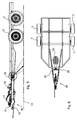
- FIG. 6 shows a plan view of a motor vehicle trailer 60 which has four wheels 2 in this example.
- the housing 20 of the switching valve 9 according to the invention which contains the at least one radar unit 15, is fastened to the transverse frame 40 of the drawbar 50.
- the surface 60 scanned by the at least one radar unit 15 on the road surface 53 has the shape of an oval. It may also be possible, depending on the design of the at least one radar unit 15, that the scanned area 60 on the road surface 53 has the shape of a rhombus or generally of a quadrilateral.
- FIG. 7 schematically shows an embodiment of the housing 20 of the switching valve 9 with the at least one radar unit 15, as well as the preferred emission of the at least one radar unit 15 shown dotted is the area, which from the cone of radiation emitted by the at least one radar unit 15 is being penetrated.
- the main lobe 70 of the at least one radar unit 15 is formed at an angle of preferably 45 ° in the direction of the road surface 53. In the direction of the main lobe 70, the at least one radar unit 15 can transmit the most energy, or the maximum reception sensitivity is present in this direction.
- the main lobe 70 may further be formed in a range of 30 ° to 60 °, preferably 40 ° to 50 ° in the direction of the road surface 53.
- the main lobe 70 of the at least one radar unit 15 has a width of more than 15 ° and less than 45 °.
- the main lobe 70 has a width of more than 20 ° and less than 40 °. More preferably, the main lobe 70 has a width of more than 25 ° and less than 35 °. In the illustrated embodiment FIG. 7 the preferred width of the main lobe 70 is 30 °.
- the motion detection system 14 operates most accurately when the radar unit 15 is disposed at a distance of 150 mm to 700 mm, preferably 200 mm to 600 mm, more preferably 300 mm to 500 mm, more preferably 400 mm above the road surface 53.
Landscapes
- Engineering & Computer Science (AREA)
- Transportation (AREA)
- Mechanical Engineering (AREA)
- Physics & Mathematics (AREA)
- Fluid Mechanics (AREA)
- Regulating Braking Force (AREA)
Claims (13)
- Installation de freinage à inertie pour remorque de véhicule de mobile, comprenant :- un système hydraulique de transmission de force de freinage,- une unité de commande (10),- une soupape d'inversion (9) agencée dans le système de transmission de force de freinage, qui est commutée par l'unité de commande (9) en fonction de la direction de déplacement de la remorque de véhicule automobile, et- un système de reconnaissance de déplacement (14) pour reconnaître l'immobilité ou une direction de déplacement de la remorque de véhicule automobile,caractérisée en ce que le système de reconnaissance de déplacement (14) inclut une unité radar (15) qui balaye la surface de la chaussée (53).
- Installation de freinage à inertie selon la revendication 1, caractérisée en ce que la surface (60) balayée par ladite au moins une unité radar sur la surface de la chaussée (53) présente la forme d'un ovale ou d'un losange ou d'un rectangle.
- Installation de freinage à inertie selon la revendication 1 ou 2, caractérisée en ce que le cône de rayonnement émis par ladite au moins une unité radar (15) est orienté en oblique vers l'arrière en direction de la surface de la chaussée (53).
- Installation de freinage à inertie selon l'une des revendications 1 à 3, caractérisée en ce qu'un lobe principal (70) de ladite au moins une unité radar (15) est formé sous un angle de 30° à 60°, de préférence 40° à 50°, et de manière encore préférée 45° en direction de la surface de la chaussée (53).
- Installation de freinage à inertie selon l'une des revendications 1 à 4, caractérisée en ce que le lobe principal (70) de ladite au moins une unité radar (15) présente une largeur de plus de 15° et moins de 45°, de préférence plus de 20° et moins de 40°, de manière plus préférée plus de 25° et moins de 35°, et de manière encore préférée de 30°.
- Installation de freinage à inertie selon l'une des revendications 1 à 5, caractérisée en ce que l'unité radar (15) est agencée à une distance de 150 mm à 700 mm, de préférence 200 mm à 600 mm, de manière plus préférée 300 mm à 500 mm, et de manière encore préférée 400 mm au-dessus de la surface de la chaussée (53).
- Installation de freinage à inertie selon l'une des revendications précédentes, caractérisée en ce que ladite au moins une unité radar (15) est logée dans le boîtier (20) de la soupape d'inversion (9).
- Installation de freinage à inertie selon la revendication 7, caractérisée en ce que le boîtier (20) de la soupape d'inversion (9) est un boîtier en matière plastique.
- Installation de freinage à inertie selon la revendication 7, caractérisée en ce que le boîtier (20) de la soupape d'inversion (9) est un boîtier en métal, tel que le boîtier en métal comporte au moins une fenêtre (21) qui est formée par un matériau diélectrique et ladite au moins une unité radar (15) est agencée derrière ladite au moins une fenêtre (21).
- Installation de freinage à inertie selon l'une des revendications précédentes, caractérisée en ce que l'unité de commande (10) détermine, au moyen des informations de l'unité radar (15), outre la direction de déplacement, également une vitesse et/ou un état de chargement de la remorque.
- Installation de freinage à inertie selon la revendication 10, caractérisée en ce qu'une soupape de pression résiduelle (13) est prévu dans une conduite de retour (11) du système hydraulique de transmission de force de freinage, soupape qui, dans le cas du dételage de la remorque, maintient la pression hydraulique dans le système de transmission de force de freinage dans la zone des freins de roues (3) au moins à une valeur de pression minimum à laquelle les freins de roues (3) sont encore tout juste en engagement de freinage, ladite valeur de pression minimum étant réglable par l'unité de commande (10) en fonction de l'état de chargement reconnu.
- Installation de freinage à inertie selon la revendication 10 ou 11, caractérisée en ce que l'unité de commande (10) est réalisée de telle façon que celle-ci ajuste, en fonction de l'état de chargement déterminé de la remorque, la pression de freinage dans le système de transmission de force de freinage (DEF) dans la zone des freins de roues (3) à l'état de chargement respectif.
- Installation de freinage à inertie selon l'une des revendications précédentes, caractérisée en ce que l'unité radar (15) et un radar à deux canaux, en particulier un radar Doppler.
Applications Claiming Priority (1)
| Application Number | Priority Date | Filing Date | Title |
|---|---|---|---|
| DE202014007403.8U DE202014007403U1 (de) | 2014-09-11 | 2014-09-11 | Auflaufbremsanlage für Kraftfahrzeuganhänger |
Publications (2)
| Publication Number | Publication Date |
|---|---|
| EP3000671A1 EP3000671A1 (fr) | 2016-03-30 |
| EP3000671B1 true EP3000671B1 (fr) | 2016-09-21 |
Family
ID=53716282
Family Applications (1)
| Application Number | Title | Priority Date | Filing Date |
|---|---|---|---|
| EP15002117.8A Active EP3000671B1 (fr) | 2014-09-11 | 2015-07-16 | Installation de frein a inertie pour remorque de vehicule automobile |
Country Status (2)
| Country | Link |
|---|---|
| EP (1) | EP3000671B1 (fr) |
| DE (1) | DE202014007403U1 (fr) |
Cited By (6)
| Publication number | Priority date | Publication date | Assignee | Title |
|---|---|---|---|---|
| US10670479B2 (en) | 2018-02-27 | 2020-06-02 | Methode Electronics, Inc. | Towing systems and methods using magnetic field sensing |
| US10696109B2 (en) | 2017-03-22 | 2020-06-30 | Methode Electronics Malta Ltd. | Magnetolastic based sensor assembly |
| US11084342B2 (en) | 2018-02-27 | 2021-08-10 | Methode Electronics, Inc. | Towing systems and methods using magnetic field sensing |
| US11135882B2 (en) | 2018-02-27 | 2021-10-05 | Methode Electronics, Inc. | Towing systems and methods using magnetic field sensing |
| US11221262B2 (en) | 2018-02-27 | 2022-01-11 | Methode Electronics, Inc. | Towing systems and methods using magnetic field sensing |
| US11491832B2 (en) | 2018-02-27 | 2022-11-08 | Methode Electronics, Inc. | Towing systems and methods using magnetic field sensing |
Families Citing this family (5)
| Publication number | Priority date | Publication date | Assignee | Title |
|---|---|---|---|---|
| DE102015014315A1 (de) * | 2015-11-05 | 2017-05-11 | Knott Gmbh | Auflaufbremsanlage für Kraftfahrzeuganhänger |
| DE202015106595U1 (de) | 2015-12-03 | 2017-03-07 | AL-KO Technology Austria GmbH | Stabilisierungstechnik für Fahrzeuganhänger |
| DE102016110836A1 (de) * | 2016-06-14 | 2017-12-14 | Valeo Schalter Und Sensoren Gmbh | Verfahren zum Vorbereiten einer Änderung eines Betriebszustands eines Gespanns, Fahrerassistenzsystem und Kraftfahrzeug |
| DE102016222549B4 (de) | 2016-11-16 | 2019-05-16 | Audi Ag | Verfahren zum Ermitteln einer Anhängerinformation und Kraftfahrzeug |
| DE102020204924B4 (de) * | 2020-04-17 | 2024-09-26 | Volkswagen Aktiengesellschaft | Bremssystem für ein Anhängerfahrzeug und Anhängerfahrzeug mit einem solchen Bremssystem |
Family Cites Families (5)
| Publication number | Priority date | Publication date | Assignee | Title |
|---|---|---|---|---|
| US3701568A (en) * | 1970-09-30 | 1972-10-31 | Bendix Corp | Adaptive braking system utilizing doppler radar |
| JP3675240B2 (ja) * | 1999-07-19 | 2005-07-27 | 日産自動車株式会社 | 車両用追従制御装置 |
| DE20117647U1 (de) | 2001-11-01 | 2003-01-09 | Knott GmbH, 83125 Eggstätt | Rückfahrsystem für Auflaufbremsanlagen von Anhängern mit hydraulischer Bremskraftübertragungseinrichtung |
| US7273260B2 (en) * | 2003-02-13 | 2007-09-25 | Hopkins Manufacturing Corporation | Electronic breakaway device |
| US7227474B2 (en) * | 2005-01-25 | 2007-06-05 | Vistoen Global Technologies, Inc. | Object detection system: zone matching and programmability |
-
2014
- 2014-09-11 DE DE202014007403.8U patent/DE202014007403U1/de not_active Expired - Lifetime
-
2015
- 2015-07-16 EP EP15002117.8A patent/EP3000671B1/fr active Active
Non-Patent Citations (1)
| Title |
|---|
| None * |
Cited By (7)
| Publication number | Priority date | Publication date | Assignee | Title |
|---|---|---|---|---|
| US10696109B2 (en) | 2017-03-22 | 2020-06-30 | Methode Electronics Malta Ltd. | Magnetolastic based sensor assembly |
| US10940726B2 (en) | 2017-03-22 | 2021-03-09 | Methode Electronics Malta Ltd. | Magnetoelastic based sensor assembly |
| US10670479B2 (en) | 2018-02-27 | 2020-06-02 | Methode Electronics, Inc. | Towing systems and methods using magnetic field sensing |
| US11084342B2 (en) | 2018-02-27 | 2021-08-10 | Methode Electronics, Inc. | Towing systems and methods using magnetic field sensing |
| US11135882B2 (en) | 2018-02-27 | 2021-10-05 | Methode Electronics, Inc. | Towing systems and methods using magnetic field sensing |
| US11221262B2 (en) | 2018-02-27 | 2022-01-11 | Methode Electronics, Inc. | Towing systems and methods using magnetic field sensing |
| US11491832B2 (en) | 2018-02-27 | 2022-11-08 | Methode Electronics, Inc. | Towing systems and methods using magnetic field sensing |
Also Published As
| Publication number | Publication date |
|---|---|
| EP3000671A1 (fr) | 2016-03-30 |
| DE202014007403U1 (de) | 2015-08-06 |
Similar Documents
| Publication | Publication Date | Title |
|---|---|---|
| EP3000671B1 (fr) | Installation de frein a inertie pour remorque de vehicule automobile | |
| EP2913236B1 (fr) | Module de freinage pour un véhicule de traction à freinage hydraulique pouvant être couplé à une remorque à freinage pneumatique | |
| EP2893527B1 (fr) | Système et procédé de fonctionnement d'un véhicule tracté ou d'un train routier | |
| EP2891586B1 (fr) | Remorque dotée d'un système de freinage pneumatique | |
| EP1308358B1 (fr) | Système de freinage hydraulique à inertie avec un système de marche arrière pour remorques | |
| DE102012010630A1 (de) | Steuerverfahren für elektronisches Parkbremssystem | |
| EP1674366B1 (fr) | Système de freinage électro-hydraulique pour des remorques de véhicules automobiles pourvues de freins à inertie | |
| EP3165419B1 (fr) | Frein d`inertie pour remorque | |
| DE202016104675U1 (de) | Zusatzbremseinrichtung für einen auflaufgebremsten Fahrzeuganhänger sowie Fahrzeuganhänger | |
| DE102009060165A1 (de) | Verfahren und Vorrichtung zum Ausparken eines Fahrzeugs | |
| DE60312462T2 (de) | Radfahrzeug mit einem Drehturm | |
| DE102015005361A1 (de) | Schutzvorrichtung für ein schwenkbares Flügelelement eines Fahrzeugs sowie Verfahren zum Schützen eines schwenkbaren Flügelelements eines Fahrzeugs | |
| DE102015204900A1 (de) | Kugelschwenkmodul und Verfahren zum Betreiben eines Kugelschwenkmoduls | |
| EP3696032B1 (fr) | Remorque de véhicule pourvue de dispositif de récupération d'énergie et dispositif hydraulique de transmission de force de freinage | |
| DE102018102398B4 (de) | Verfahren und System zur Unterstützung eines Fahrers eines Fahrzeugs, insbesondere eines Nutzfahrzeugs, sowie Fahrzeug zur Durchführung eines solchen Verfahrens oder Systems | |
| EP1809512A1 (fr) | Systeme d'aide au stationnement destine a un vehicule et procede d'aide au stationnement | |
| DD263502A5 (de) | Vorrichtung fuer eine dehnbare kupplung fuer lkws | |
| WO2000055030A1 (fr) | Systeme de direction d'un vehicule | |
| EP3461707A1 (fr) | Système de commande d'un dispositif de freinage à commande hydraulique | |
| EP2965960B1 (fr) | Frein de stationnement | |
| DE202004006324U1 (de) | Bremseinrichtung für einen Fahrzeuganhänger | |
| DE102009058967A1 (de) | Fahrpedal | |
| EP2821811A1 (fr) | Dispositif auxiliaire pour marche arrière | |
| DE202005019223U1 (de) | Auflaufbremsanlage für Kraftfahrzeuganhänger mit Wegmesseinrichtung für Zugstange | |
| DE202006010199U1 (de) | Bremseinrichtung für einen Fahrzeuganhänger |
Legal Events
| Date | Code | Title | Description |
|---|---|---|---|
| PUAI | Public reference made under article 153(3) epc to a published international application that has entered the european phase |
Free format text: ORIGINAL CODE: 0009012 |
|
| AK | Designated contracting states |
Kind code of ref document: A1 Designated state(s): AL AT BE BG CH CY CZ DE DK EE ES FI FR GB GR HR HU IE IS IT LI LT LU LV MC MK MT NL NO PL PT RO RS SE SI SK SM TR |
|
| AX | Request for extension of the european patent |
Extension state: BA ME |
|
| 17P | Request for examination filed |
Effective date: 20160310 |
|
| RBV | Designated contracting states (corrected) |
Designated state(s): AL AT BE BG CH CY CZ DE DK EE ES FI FR GB GR HR HU IE IS IT LI LT LU LV MC MK MT NL NO PL PT RO RS SE SI SK SM TR |
|
| GRAP | Despatch of communication of intention to grant a patent |
Free format text: ORIGINAL CODE: EPIDOSNIGR1 |
|
| INTG | Intention to grant announced |
Effective date: 20160707 |
|
| GRAS | Grant fee paid |
Free format text: ORIGINAL CODE: EPIDOSNIGR3 |
|
| GRAA | (expected) grant |
Free format text: ORIGINAL CODE: 0009210 |
|
| AK | Designated contracting states |
Kind code of ref document: B1 Designated state(s): AL AT BE BG CH CY CZ DE DK EE ES FI FR GB GR HR HU IE IS IT LI LT LU LV MC MK MT NL NO PL PT RO RS SE SI SK SM TR |
|
| REG | Reference to a national code |
Ref country code: GB Ref legal event code: FG4D Free format text: NOT ENGLISH |
|
| REG | Reference to a national code |
Ref country code: CH Ref legal event code: EP |
|
| REG | Reference to a national code |
Ref country code: AT Ref legal event code: REF Ref document number: 830763 Country of ref document: AT Kind code of ref document: T Effective date: 20161015 |
|
| REG | Reference to a national code |
Ref country code: IE Ref legal event code: FG4D Free format text: LANGUAGE OF EP DOCUMENT: GERMAN |
|
| REG | Reference to a national code |
Ref country code: DE Ref legal event code: R096 Ref document number: 502015000162 Country of ref document: DE |
|
| REG | Reference to a national code |
Ref country code: LT Ref legal event code: MG4D Ref country code: NL Ref legal event code: MP Effective date: 20160921 |
|
| PG25 | Lapsed in a contracting state [announced via postgrant information from national office to epo] |
Ref country code: LT Free format text: LAPSE BECAUSE OF FAILURE TO SUBMIT A TRANSLATION OF THE DESCRIPTION OR TO PAY THE FEE WITHIN THE PRESCRIBED TIME-LIMIT Effective date: 20160921 Ref country code: FI Free format text: LAPSE BECAUSE OF FAILURE TO SUBMIT A TRANSLATION OF THE DESCRIPTION OR TO PAY THE FEE WITHIN THE PRESCRIBED TIME-LIMIT Effective date: 20160921 Ref country code: RS Free format text: LAPSE BECAUSE OF FAILURE TO SUBMIT A TRANSLATION OF THE DESCRIPTION OR TO PAY THE FEE WITHIN THE PRESCRIBED TIME-LIMIT Effective date: 20160921 Ref country code: NO Free format text: LAPSE BECAUSE OF FAILURE TO SUBMIT A TRANSLATION OF THE DESCRIPTION OR TO PAY THE FEE WITHIN THE PRESCRIBED TIME-LIMIT Effective date: 20161221 |
|
| PG25 | Lapsed in a contracting state [announced via postgrant information from national office to epo] |
Ref country code: NL Free format text: LAPSE BECAUSE OF FAILURE TO SUBMIT A TRANSLATION OF THE DESCRIPTION OR TO PAY THE FEE WITHIN THE PRESCRIBED TIME-LIMIT Effective date: 20160921 Ref country code: GR Free format text: LAPSE BECAUSE OF FAILURE TO SUBMIT A TRANSLATION OF THE DESCRIPTION OR TO PAY THE FEE WITHIN THE PRESCRIBED TIME-LIMIT Effective date: 20161222 Ref country code: SE Free format text: LAPSE BECAUSE OF FAILURE TO SUBMIT A TRANSLATION OF THE DESCRIPTION OR TO PAY THE FEE WITHIN THE PRESCRIBED TIME-LIMIT Effective date: 20160921 Ref country code: LV Free format text: LAPSE BECAUSE OF FAILURE TO SUBMIT A TRANSLATION OF THE DESCRIPTION OR TO PAY THE FEE WITHIN THE PRESCRIBED TIME-LIMIT Effective date: 20160921 |
|
| PG25 | Lapsed in a contracting state [announced via postgrant information from national office to epo] |
Ref country code: EE Free format text: LAPSE BECAUSE OF FAILURE TO SUBMIT A TRANSLATION OF THE DESCRIPTION OR TO PAY THE FEE WITHIN THE PRESCRIBED TIME-LIMIT Effective date: 20160921 Ref country code: RO Free format text: LAPSE BECAUSE OF FAILURE TO SUBMIT A TRANSLATION OF THE DESCRIPTION OR TO PAY THE FEE WITHIN THE PRESCRIBED TIME-LIMIT Effective date: 20160921 |
|
| PG25 | Lapsed in a contracting state [announced via postgrant information from national office to epo] |
Ref country code: CZ Free format text: LAPSE BECAUSE OF FAILURE TO SUBMIT A TRANSLATION OF THE DESCRIPTION OR TO PAY THE FEE WITHIN THE PRESCRIBED TIME-LIMIT Effective date: 20160921 Ref country code: PT Free format text: LAPSE BECAUSE OF FAILURE TO SUBMIT A TRANSLATION OF THE DESCRIPTION OR TO PAY THE FEE WITHIN THE PRESCRIBED TIME-LIMIT Effective date: 20170123 Ref country code: ES Free format text: LAPSE BECAUSE OF FAILURE TO SUBMIT A TRANSLATION OF THE DESCRIPTION OR TO PAY THE FEE WITHIN THE PRESCRIBED TIME-LIMIT Effective date: 20160921 Ref country code: SK Free format text: LAPSE BECAUSE OF FAILURE TO SUBMIT A TRANSLATION OF THE DESCRIPTION OR TO PAY THE FEE WITHIN THE PRESCRIBED TIME-LIMIT Effective date: 20160921 Ref country code: SM Free format text: LAPSE BECAUSE OF FAILURE TO SUBMIT A TRANSLATION OF THE DESCRIPTION OR TO PAY THE FEE WITHIN THE PRESCRIBED TIME-LIMIT Effective date: 20160921 Ref country code: PL Free format text: LAPSE BECAUSE OF FAILURE TO SUBMIT A TRANSLATION OF THE DESCRIPTION OR TO PAY THE FEE WITHIN THE PRESCRIBED TIME-LIMIT Effective date: 20160921 Ref country code: BG Free format text: LAPSE BECAUSE OF FAILURE TO SUBMIT A TRANSLATION OF THE DESCRIPTION OR TO PAY THE FEE WITHIN THE PRESCRIBED TIME-LIMIT Effective date: 20161221 Ref country code: IS Free format text: LAPSE BECAUSE OF FAILURE TO SUBMIT A TRANSLATION OF THE DESCRIPTION OR TO PAY THE FEE WITHIN THE PRESCRIBED TIME-LIMIT Effective date: 20170121 |
|
| REG | Reference to a national code |
Ref country code: DE Ref legal event code: R097 Ref document number: 502015000162 Country of ref document: DE |
|
| PG25 | Lapsed in a contracting state [announced via postgrant information from national office to epo] |
Ref country code: IT Free format text: LAPSE BECAUSE OF FAILURE TO SUBMIT A TRANSLATION OF THE DESCRIPTION OR TO PAY THE FEE WITHIN THE PRESCRIBED TIME-LIMIT Effective date: 20160921 |
|
| REG | Reference to a national code |
Ref country code: FR Ref legal event code: PLFP Year of fee payment: 3 |
|
| PLBE | No opposition filed within time limit |
Free format text: ORIGINAL CODE: 0009261 |
|
| STAA | Information on the status of an ep patent application or granted ep patent |
Free format text: STATUS: NO OPPOSITION FILED WITHIN TIME LIMIT |
|
| PG25 | Lapsed in a contracting state [announced via postgrant information from national office to epo] |
Ref country code: DK Free format text: LAPSE BECAUSE OF FAILURE TO SUBMIT A TRANSLATION OF THE DESCRIPTION OR TO PAY THE FEE WITHIN THE PRESCRIBED TIME-LIMIT Effective date: 20160921 |
|
| 26N | No opposition filed |
Effective date: 20170622 |
|
| PG25 | Lapsed in a contracting state [announced via postgrant information from national office to epo] |
Ref country code: SI Free format text: LAPSE BECAUSE OF FAILURE TO SUBMIT A TRANSLATION OF THE DESCRIPTION OR TO PAY THE FEE WITHIN THE PRESCRIBED TIME-LIMIT Effective date: 20160921 |
|
| REG | Reference to a national code |
Ref country code: IE Ref legal event code: MM4A |
|
| PG25 | Lapsed in a contracting state [announced via postgrant information from national office to epo] |
Ref country code: IE Free format text: LAPSE BECAUSE OF NON-PAYMENT OF DUE FEES Effective date: 20170716 |
|
| REG | Reference to a national code |
Ref country code: BE Ref legal event code: MM Effective date: 20170731 |
|
| PG25 | Lapsed in a contracting state [announced via postgrant information from national office to epo] |
Ref country code: LU Free format text: LAPSE BECAUSE OF NON-PAYMENT OF DUE FEES Effective date: 20170716 |
|
| REG | Reference to a national code |
Ref country code: DE Ref legal event code: R082 Ref document number: 502015000162 Country of ref document: DE Representative=s name: FLACH BAUER & PARTNER PATENTANWAELTE MBB, DE Ref country code: DE Ref legal event code: R082 Ref document number: 502015000162 Country of ref document: DE Representative=s name: FLACH BAUER STAHL PATENTANWAELTE PARTNERSCHAFT, DE |
|
| REG | Reference to a national code |
Ref country code: FR Ref legal event code: PLFP Year of fee payment: 4 |
|
| PG25 | Lapsed in a contracting state [announced via postgrant information from national office to epo] |
Ref country code: BE Free format text: LAPSE BECAUSE OF NON-PAYMENT OF DUE FEES Effective date: 20170731 |
|
| PG25 | Lapsed in a contracting state [announced via postgrant information from national office to epo] |
Ref country code: MT Free format text: LAPSE BECAUSE OF FAILURE TO SUBMIT A TRANSLATION OF THE DESCRIPTION OR TO PAY THE FEE WITHIN THE PRESCRIBED TIME-LIMIT Effective date: 20160921 |
|
| PG25 | Lapsed in a contracting state [announced via postgrant information from national office to epo] |
Ref country code: AL Free format text: LAPSE BECAUSE OF FAILURE TO SUBMIT A TRANSLATION OF THE DESCRIPTION OR TO PAY THE FEE WITHIN THE PRESCRIBED TIME-LIMIT Effective date: 20160921 |
|
| REG | Reference to a national code |
Ref country code: CH Ref legal event code: PL |
|
| PG25 | Lapsed in a contracting state [announced via postgrant information from national office to epo] |
Ref country code: CH Free format text: LAPSE BECAUSE OF NON-PAYMENT OF DUE FEES Effective date: 20180731 Ref country code: LI Free format text: LAPSE BECAUSE OF NON-PAYMENT OF DUE FEES Effective date: 20180731 |
|
| PG25 | Lapsed in a contracting state [announced via postgrant information from national office to epo] |
Ref country code: MC Free format text: LAPSE BECAUSE OF FAILURE TO SUBMIT A TRANSLATION OF THE DESCRIPTION OR TO PAY THE FEE WITHIN THE PRESCRIBED TIME-LIMIT Effective date: 20160921 Ref country code: HU Free format text: LAPSE BECAUSE OF FAILURE TO SUBMIT A TRANSLATION OF THE DESCRIPTION OR TO PAY THE FEE WITHIN THE PRESCRIBED TIME-LIMIT; INVALID AB INITIO Effective date: 20150716 |
|
| PG25 | Lapsed in a contracting state [announced via postgrant information from national office to epo] |
Ref country code: CY Free format text: LAPSE BECAUSE OF FAILURE TO SUBMIT A TRANSLATION OF THE DESCRIPTION OR TO PAY THE FEE WITHIN THE PRESCRIBED TIME-LIMIT Effective date: 20160921 |
|
| PG25 | Lapsed in a contracting state [announced via postgrant information from national office to epo] |
Ref country code: MK Free format text: LAPSE BECAUSE OF FAILURE TO SUBMIT A TRANSLATION OF THE DESCRIPTION OR TO PAY THE FEE WITHIN THE PRESCRIBED TIME-LIMIT Effective date: 20160921 |
|
| PG25 | Lapsed in a contracting state [announced via postgrant information from national office to epo] |
Ref country code: TR Free format text: LAPSE BECAUSE OF FAILURE TO SUBMIT A TRANSLATION OF THE DESCRIPTION OR TO PAY THE FEE WITHIN THE PRESCRIBED TIME-LIMIT Effective date: 20160921 |
|
| PG25 | Lapsed in a contracting state [announced via postgrant information from national office to epo] |
Ref country code: HR Free format text: LAPSE BECAUSE OF FAILURE TO SUBMIT A TRANSLATION OF THE DESCRIPTION OR TO PAY THE FEE WITHIN THE PRESCRIBED TIME-LIMIT Effective date: 20160921 |
|
| REG | Reference to a national code |
Ref country code: AT Ref legal event code: MM01 Ref document number: 830763 Country of ref document: AT Kind code of ref document: T Effective date: 20200716 |
|
| PG25 | Lapsed in a contracting state [announced via postgrant information from national office to epo] |
Ref country code: AT Free format text: LAPSE BECAUSE OF NON-PAYMENT OF DUE FEES Effective date: 20200716 |
|
| P01 | Opt-out of the competence of the unified patent court (upc) registered |
Effective date: 20230524 |
|
| PGFP | Annual fee paid to national office [announced via postgrant information from national office to epo] |
Ref country code: DE Payment date: 20250722 Year of fee payment: 11 |
|
| PGFP | Annual fee paid to national office [announced via postgrant information from national office to epo] |
Ref country code: GB Payment date: 20250724 Year of fee payment: 11 |
|
| PGFP | Annual fee paid to national office [announced via postgrant information from national office to epo] |
Ref country code: FR Payment date: 20250723 Year of fee payment: 11 |