EP3000633B1 - Fahrzeugklimaanlagendichtung und anordnung mit einer fahrzeugklimaanlagendichtung - Google Patents
Fahrzeugklimaanlagendichtung und anordnung mit einer fahrzeugklimaanlagendichtung Download PDFInfo
- Publication number
- EP3000633B1 EP3000633B1 EP15186331.3A EP15186331A EP3000633B1 EP 3000633 B1 EP3000633 B1 EP 3000633B1 EP 15186331 A EP15186331 A EP 15186331A EP 3000633 B1 EP3000633 B1 EP 3000633B1
- Authority
- EP
- European Patent Office
- Prior art keywords
- seal
- side structure
- intermediate body
- fluid line
- air conditioning
- Prior art date
- Legal status (The legal status is an assumption and is not a legal conclusion. Google has not performed a legal analysis and makes no representation as to the accuracy of the status listed.)
- Not-in-force
Links
Images

Classifications
-
- B—PERFORMING OPERATIONS; TRANSPORTING
- B60—VEHICLES IN GENERAL
- B60H—ARRANGEMENTS OF HEATING, COOLING, VENTILATING OR OTHER AIR-TREATING DEVICES SPECIALLY ADAPTED FOR PASSENGER OR GOODS SPACES OF VEHICLES
- B60H1/00—Heating, cooling or ventilating devices
- B60H1/00507—Details, e.g. mounting arrangements, desaeration devices
- B60H1/00557—Details of ducts or cables
- B60H1/00571—Details of ducts or cables of liquid ducts, e.g. for coolant liquids or refrigerants
-
- B—PERFORMING OPERATIONS; TRANSPORTING
- B60—VEHICLES IN GENERAL
- B60H—ARRANGEMENTS OF HEATING, COOLING, VENTILATING OR OTHER AIR-TREATING DEVICES SPECIALLY ADAPTED FOR PASSENGER OR GOODS SPACES OF VEHICLES
- B60H1/00—Heating, cooling or ventilating devices
- B60H1/00507—Details, e.g. mounting arrangements, desaeration devices
- B60H2001/00635—Air-tight sealing devices
-
- F—MECHANICAL ENGINEERING; LIGHTING; HEATING; WEAPONS; BLASTING
- F16—ENGINEERING ELEMENTS AND UNITS; GENERAL MEASURES FOR PRODUCING AND MAINTAINING EFFECTIVE FUNCTIONING OF MACHINES OR INSTALLATIONS; THERMAL INSULATION IN GENERAL
- F16L—PIPES; JOINTS OR FITTINGS FOR PIPES; SUPPORTS FOR PIPES, CABLES OR PROTECTIVE TUBING; MEANS FOR THERMAL INSULATION IN GENERAL
- F16L41/00—Branching pipes; Joining pipes to walls
- F16L41/08—Joining pipes to walls or pipes, the joined pipe axis being perpendicular to the plane of a wall or to the axis of another pipe
- F16L41/086—Joining pipes to walls or pipes, the joined pipe axis being perpendicular to the plane of a wall or to the axis of another pipe fixed with screws
Definitions
- a seal according to the preamble of claim 1 is disclosed in US 2009/0250559 A1 .
- Such seals are used for example in order to seal the leadthrough for fluid lines through a bulkhead between a vehicle interior and an engine compartment from the penetration of moisture from the engine compartment.
- the fluid lines connect an air conditioning module in the vehicle interior, said air conditioning module comprising the evaporator, to modules of the vehicle air conditioner that are arranged in the engine compartment and contain, inter alia , the compressor. It is the object of the invention to optimize the mounting of fluid lines in a vehicle air conditioning system.
- the anti-twist device is preferably configured as a simple plug connection, in the case of which the seal-side structure and the line-side structure can be joined together and taken apart again in particular in a rectilinear movement without the use of tools.
- the seal-side structure is a blind hole in the intermediate body.
- a complementary protrusion on a flange connected fixedly to the fluid line can then be used as the line-side structure, for example. Twisting of the flange and thus of the fluid line with respect to the intermediate body can be effectively prevented in this way.
- the gap between the fluid line and the circumferential wall of the leadthrough is preferably sealed against the passage of gases and/or liquids, for example by introduced sealing material or a portion of the resilient sealing element of the seal.
- the intermediate body can be radially surrounded by a portion of the resilient sealing element, which can be formed in particular in a pot-like manner. In the case of a multipart intermediate body, the intermediate-body parts can then be held together by the resilient sealing element, thereby simplifying mounting.
- the seal can be designed for example for abutment against the bulkhead of the vehicle between the engine compartment and the vehicle interior.
- the resilient sealing element can have a bulkhead portion that bears against the bulkhead, and also further portions which bear against the housing of the air conditioning module and/or against the fluid line or the flange of the fluid line.
- the vehicle air conditioning system seal in the case of an assembly having a vehicle air conditioning system seal which is arranged at an opening in a bulkhead between an engine compartment of the vehicle and the vehicle interior, and at least one fluid line, extending through a leadthrough in the vehicle air conditioning system seal, of the air conditioning system, provision is made for the vehicle air conditioning system seal to have a resilient sealing element and a rigid intermediate body, and also an anti-twist device which limits twisting of the fluid line with respect to the vehicle air conditioning system seal.
- the anti-twist device comprises a seal-side structure on the intermediate body and a line-side structure formed on the fluid line. The line-side structure comes into abutment against the seal-side structure at least when the fluid line is twisted through a maximum twist angle with respect to the seal.
- the anti-twist device provides a mounting aid for tightening the fluid lines. Torsion forces which occur during the tightening of the connections of the fluid lines of the air conditioning system are dissipated into the housing via the intermediate body.
- the maximum rotation angle is preferably limited to a value of less than about 0.1° to 3°.
- the seal can be configured as described above.
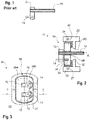
- the seal 18 consists here of a resilient sealing element 24 and of a rigid intermediate body 26 that is received within the resilient sealing element 24.
- the resilient sealing element 24 is produced as a one-piece body made of a suitable elastomer and has in this case a cylindrical circumferential wall portion 27 which surrounds the intermediate body 26.
- a leadthrough opening 28 Formed in the rigid intermediate body 26 is a leadthrough opening 28 through which the fluid line 10 extends. It is possible for a plurality of leadthrough openings 28 to be present in the intermediate body 26, as is illustrated for example in Figures 3 and 8 . However, it is also possible to provide only a single leadthrough opening 28.
- the seal 18 is inserted into an opening 30 in the housing 22, wherein the circumferential wall portion 27 is located between the intermediate body 26 and the inner wall of the opening 30 in the housing 22.
- the dimensions are selected such that the seal 18 is held in the opening 30 with a desired clamping force.
- a sealing material 32 in order to create gas- and/or liquid-tight sealing of the leadthrough opening 28.
- the sealing material could also be formed by a portion of the resilient sealing element 24 of the seal 18, said resilient sealing element 24 for example enclosing the fluid line 10 in a manner axially adjoining the intermediate body 26.
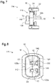
- Figures 7 and 8 show a second embodiment of an assembly 116. Components that are already known from the first embodiment and are not changed or are only changed insignificantly retain their already introduced reference signs.
Landscapes
- Physics & Mathematics (AREA)
- Thermal Sciences (AREA)
- Engineering & Computer Science (AREA)
- Mechanical Engineering (AREA)
- Air-Conditioning For Vehicles (AREA)
Claims (8)
- Fahrzeugklimaanlagendichtung, die ein elastisches Dichtelement (24) und einen starren zwischenliegenden Körper (26; 126) aufweist, in dem wenigstens eine Durchführungsöffnung (28) für eine Flüssigkeitsleitung (10) der Fahrzeugklimaanlage ausgebildet ist, wobei eine Verdrehsicherung, die ein Verdrehen der Flüssigkeitsleitung (10) in Bezug auf die Fahrzeugklimaanlagendichtung (18; 118) begrenzt, vorgesehen ist, wobei die Verdrehsicherung eine dichtungsseitige Struktur (34; 134) umfasst, die an dem zwischenliegenden Körper (26; 126) vorgesehen ist und mit einer leitungsseitigen Struktur (36; 136), die an der Flüssigkeitsleitung (10) ausgebildet ist, zusammenwirken kann, und die dichtungsseitige Struktur (34; 134) auf eine solche Weise ausgelegt ist, dass die leitungsseitige Struktur (36; 136) zur Anlage an der dichtungsseitigen Struktur (34; 134) wenigstens dann kommt, wenn die Flüssigkeitsleitung (10) in einem maximalen Verdrehwinkel in Bezug auf den zwischenliegenden Körper (26; 126) verdreht wird,
dadurch gekennzeichnet, dass
die dichtungsseitige Struktur (34) ein Blindloch in dem zwischenliegenden Körper (26) ist und der zwischenliegende Körper (26; 126) eine Vielzahl von Teilen (26a, 26b; 126a, 126b) aufweist, die auf eine solche Weise um die Flüssigkeitsleitung (10) herum zusammengesetzt werden können, dass sie die Flüssigkeitsleitung (10) umgreifen, wobei jeder der Teile (26a, 26b; 126a, 126b) einen Abschnitt der Innenwand der Durchführungsöffnung (28) festlegt. - Fahrzeugklimaanlagendichtung nach Anspruch 1,
dadurch gekennzeichnet, dass die dichtungsseitige Struktur (134) wenigstens einen an dem zwischenliegenden Körper (126) ausgebildeten Anschlagpunkt (140) aufweist. - Anordnung, die eine Fahrzeugklimaanlagendichtung nach einem der vorhergehenden Ansprüche aufweist und wenigstens eine Durchführungsöffnung (28) und eine Flüssigkeitsleitung (10) umfasst, die sich durch die Durchführungsöffnung (28) der Klimaanlage erstreckt, wobei die Fahrzeugklimaanlagendichtung (18; 118) ein elastisches Dichtelement (24) und einen starren zwischenliegenden Körper (26; 126) aufweist, und wobei eine Verdrehsicherung, die ein Verdrehen der Flüssigkeitsleitung (10) in Bezug auf die Fahrzeugklimaanlagendichtung (18; 118) begrenzt, vorgesehen ist und die Verdrehsicherung eine dichtungsseitige Struktur (34; 134) an dem zwischenliegenden Körper (26; 126) und eine leitungsseitige Struktur (36; 136), die an der Flüssigkeitsleitung (10) ausgebildet ist, umfasst, wobei die leitungsseitige Struktur (36; 136) zur Anlage an der dichtungsseitigen Struktur (34; 134) wenigstens dann kommt, wenn die Flüssigkeitsleitung (10) in einem maximalen Verdrehwinkel in Bezug auf den zwischenliegenden Körper (26; 126) verdreht wird.
- Anordnung nach Anspruch 3, dadurch gekennzeichnet, dass die dichtungsseitige Struktur (34) durch ein Blindloch in dem zwischenliegenden Körper (26) ausgebildet ist und die leitungsseitige Struktur (36) durch einen Befestigungsstift ausgebildet ist, der in das Blindloch eingreift.
- Anordnung nach Anspruch 4, dadurch gekennzeichnet, dass der Befestigungsstift ein dem zwischenliegenden Körper (26) zugewandter verlängerter Abschnitt eines Positionierungsstifts (14) an einem Flansch (12) der Flüssigkeitsleitung (10) ist.
- Anordnung nach Anspruch 3, dadurch gekennzeichnet, dass die dichtungsseitige Struktur (134) wenigstens einen Anschlagpunkt (140) umfasst und die leitungsseitige Struktur (136) wenigstens eine Anschlagfläche (142) umfasst, die wenigstens dann in Kontakt mit dem Anschlagpunkt (140) kommt, wenn die Flüssigkeitsleitung (10) in dem maximalen Verdrehwinkel in Bezug auf den zwischenliegenden Körper (126) verdreht ist.
- Anordnung nach Anspruch 6, dadurch gekennzeichnet, dass die dichtungsseitige Struktur (134) eine Ausnehmung und/oder einen Vorsprung mit wenigstens zwei Wandflächen an einer Endfläche des zwischenliegenden Körpers (126) umfasst, wobei sich die Anschlagpunkte (140) in den Wandflächen befinden.
- Anordnung nach beiden der Ansprüche 6 und 7,
dadurch gekennzeichnet, dass die dichtungsseitige Struktur (134) und die leitungsseitige Struktur (136) eine formschlüssige Verbindung wenigstens über einen Teil des Umfangs des Flansches (12) an der Flüssigkeitsleitung (10) bilden.
Applications Claiming Priority (1)
| Application Number | Priority Date | Filing Date | Title |
|---|---|---|---|
| DE102014113926.7A DE102014113926A1 (de) | 2014-09-25 | 2014-09-25 | Fahrzeugklimaanlagensystemdichtung und Baugruppe mit einer Fahrzeugklimaanlagensystemdichtung |
Publications (2)
| Publication Number | Publication Date |
|---|---|
| EP3000633A1 EP3000633A1 (de) | 2016-03-30 |
| EP3000633B1 true EP3000633B1 (de) | 2018-10-17 |
Family
ID=54198991
Family Applications (1)
| Application Number | Title | Priority Date | Filing Date |
|---|---|---|---|
| EP15186331.3A Not-in-force EP3000633B1 (de) | 2014-09-25 | 2015-09-22 | Fahrzeugklimaanlagendichtung und anordnung mit einer fahrzeugklimaanlagendichtung |
Country Status (2)
| Country | Link |
|---|---|
| EP (1) | EP3000633B1 (de) |
| DE (1) | DE102014113926A1 (de) |
Families Citing this family (1)
| Publication number | Priority date | Publication date | Assignee | Title |
|---|---|---|---|---|
| DE102024111888A1 (de) * | 2024-04-29 | 2025-10-30 | Audi Aktiengesellschaft | Blockverbindungsanordnung mit einstückigem Sicherungsvorsprung für eine Kälteanlage eines Kraftfahrzeugs und Kälteanlage mit einer solchen Blockverbindungsanordnung |
Family Cites Families (3)
| Publication number | Priority date | Publication date | Assignee | Title |
|---|---|---|---|---|
| JPH01289714A (ja) * | 1988-05-16 | 1989-11-21 | Hitachi Ltd | 自動車用配管接続構造 |
| US8430365B2 (en) * | 2008-04-03 | 2013-04-30 | Illinois Tool Works Inc. | Tube holding block assembly |
| FR2941518B1 (fr) * | 2009-01-26 | 2012-08-10 | Valeo Systemes Thermiques | Installation de chauffage, ventilation et/ou climatisation comprenant un dispositif d'assemblage d'un echangeur de chaleur |
-
2014
- 2014-09-25 DE DE102014113926.7A patent/DE102014113926A1/de not_active Withdrawn
-
2015
- 2015-09-22 EP EP15186331.3A patent/EP3000633B1/de not_active Not-in-force
Non-Patent Citations (1)
| Title |
|---|
| None * |
Also Published As
| Publication number | Publication date |
|---|---|
| EP3000633A1 (de) | 2016-03-30 |
| DE102014113926A1 (de) | 2016-03-31 |
Similar Documents
| Publication | Publication Date | Title |
|---|---|---|
| US9745926B2 (en) | Fluid line coupling | |
| US10711922B2 (en) | Wall feed-through element for a fluid line and wall feed-through | |
| US9784281B2 (en) | Exhaust-gas turbocharger | |
| KR101906654B1 (ko) | 플러그-인 커넥터 제조 방법 및 플러그-인 커넥터 | |
| KR20170074210A (ko) | 압축기 | |
| EP3000632B1 (de) | Fahrzeugklimaanlagenmoduldichtung und anordnung mit einer fahrzeugklimaanlagenmoduldichtung | |
| US10036390B2 (en) | Pump unit | |
| US10305349B2 (en) | Actuator with latching connection | |
| EP3000633B1 (de) | Fahrzeugklimaanlagendichtung und anordnung mit einer fahrzeugklimaanlagendichtung | |
| MX2010007635A (es) | Montaje de acoplamiento para una unidad de aire acondicionado de un vehiculo. | |
| EP1741967B1 (de) | Schnellkupplungsvorrichtung für kraftfahrzeugleitungen | |
| US7066208B2 (en) | Hydraulic accumulator | |
| JP2008256091A (ja) | 配管継手 | |
| US9657876B2 (en) | Screw connection device for connecting two pipes | |
| US8956069B2 (en) | Tool-free connector and mounting arrangement | |
| US10539146B2 (en) | Centrifugal pump | |
| EP3652070B1 (de) | Kraftstofftankkommunikationssysteme | |
| JP2007092773A (ja) | 目玉継手の組立構造体 | |
| US12379053B2 (en) | Connecting device for a sealed exchange of fluid between two components, connecting system and brake system | |
| US12169039B2 (en) | Tamper-resistant hydraulic connections | |
| WO2015027940A1 (en) | A coupling structure for coupling fluid passage members | |
| KR20100033561A (ko) | 에어컨 호스의 결합방법 및 그 결합구조 | |
| WO2024209880A1 (ja) | 流路形成装置 | |
| EP3947969A1 (de) | Verdichter- oder pumpengehäuseanordnung und verfahren zur montage eines verdichter- oder pumpengehäuses | |
| EP2623834B1 (de) | Verbinder für einen Hydraulik- und/oder Druckluftkreislauf, insbesondere für Industriefahrzeuge |
Legal Events
| Date | Code | Title | Description |
|---|---|---|---|
| PUAI | Public reference made under article 153(3) epc to a published international application that has entered the european phase |
Free format text: ORIGINAL CODE: 0009012 |
|
| AK | Designated contracting states |
Kind code of ref document: A1 Designated state(s): AL AT BE BG CH CY CZ DE DK EE ES FI FR GB GR HR HU IE IS IT LI LT LU LV MC MK MT NL NO PL PT RO RS SE SI SK SM TR |
|
| AX | Request for extension of the european patent |
Extension state: BA ME |
|
| 17P | Request for examination filed |
Effective date: 20160930 |
|
| RBV | Designated contracting states (corrected) |
Designated state(s): AL AT BE BG CH CY CZ DE DK EE ES FI FR GB GR HR HU IE IS IT LI LT LU LV MC MK MT NL NO PL PT RO RS SE SI SK SM TR |
|
| GRAP | Despatch of communication of intention to grant a patent |
Free format text: ORIGINAL CODE: EPIDOSNIGR1 |
|
| STAA | Information on the status of an ep patent application or granted ep patent |
Free format text: STATUS: GRANT OF PATENT IS INTENDED |
|
| RIC1 | Information provided on ipc code assigned before grant |
Ipc: F16L 41/08 20060101ALI20180418BHEP Ipc: B60H 1/00 20060101AFI20180418BHEP |
|
| INTG | Intention to grant announced |
Effective date: 20180507 |
|
| GRAS | Grant fee paid |
Free format text: ORIGINAL CODE: EPIDOSNIGR3 |
|
| GRAA | (expected) grant |
Free format text: ORIGINAL CODE: 0009210 |
|
| STAA | Information on the status of an ep patent application or granted ep patent |
Free format text: STATUS: THE PATENT HAS BEEN GRANTED |
|
| AK | Designated contracting states |
Kind code of ref document: B1 Designated state(s): AL AT BE BG CH CY CZ DE DK EE ES FI FR GB GR HR HU IE IS IT LI LT LU LV MC MK MT NL NO PL PT RO RS SE SI SK SM TR |
|
| REG | Reference to a national code |
Ref country code: GB Ref legal event code: FG4D |
|
| REG | Reference to a national code |
Ref country code: CH Ref legal event code: EP |
|
| REG | Reference to a national code |
Ref country code: IE Ref legal event code: FG4D |
|
| REG | Reference to a national code |
Ref country code: DE Ref legal event code: R096 Ref document number: 602015018196 Country of ref document: DE Ref country code: AT Ref legal event code: REF Ref document number: 1053560 Country of ref document: AT Kind code of ref document: T Effective date: 20181115 |
|
| REG | Reference to a national code |
Ref country code: NL Ref legal event code: MP Effective date: 20181017 |
|
| REG | Reference to a national code |
Ref country code: LT Ref legal event code: MG4D |
|
| REG | Reference to a national code |
Ref country code: AT Ref legal event code: MK05 Ref document number: 1053560 Country of ref document: AT Kind code of ref document: T Effective date: 20181017 |
|
| PG25 | Lapsed in a contracting state [announced via postgrant information from national office to epo] |
Ref country code: NL Free format text: LAPSE BECAUSE OF FAILURE TO SUBMIT A TRANSLATION OF THE DESCRIPTION OR TO PAY THE FEE WITHIN THE PRESCRIBED TIME-LIMIT Effective date: 20181017 |
|
| PG25 | Lapsed in a contracting state [announced via postgrant information from national office to epo] |
Ref country code: FI Free format text: LAPSE BECAUSE OF FAILURE TO SUBMIT A TRANSLATION OF THE DESCRIPTION OR TO PAY THE FEE WITHIN THE PRESCRIBED TIME-LIMIT Effective date: 20181017 Ref country code: IS Free format text: LAPSE BECAUSE OF FAILURE TO SUBMIT A TRANSLATION OF THE DESCRIPTION OR TO PAY THE FEE WITHIN THE PRESCRIBED TIME-LIMIT Effective date: 20190217 Ref country code: BG Free format text: LAPSE BECAUSE OF FAILURE TO SUBMIT A TRANSLATION OF THE DESCRIPTION OR TO PAY THE FEE WITHIN THE PRESCRIBED TIME-LIMIT Effective date: 20190117 Ref country code: PL Free format text: LAPSE BECAUSE OF FAILURE TO SUBMIT A TRANSLATION OF THE DESCRIPTION OR TO PAY THE FEE WITHIN THE PRESCRIBED TIME-LIMIT Effective date: 20181017 Ref country code: HR Free format text: LAPSE BECAUSE OF FAILURE TO SUBMIT A TRANSLATION OF THE DESCRIPTION OR TO PAY THE FEE WITHIN THE PRESCRIBED TIME-LIMIT Effective date: 20181017 Ref country code: NO Free format text: LAPSE BECAUSE OF FAILURE TO SUBMIT A TRANSLATION OF THE DESCRIPTION OR TO PAY THE FEE WITHIN THE PRESCRIBED TIME-LIMIT Effective date: 20190117 Ref country code: LT Free format text: LAPSE BECAUSE OF FAILURE TO SUBMIT A TRANSLATION OF THE DESCRIPTION OR TO PAY THE FEE WITHIN THE PRESCRIBED TIME-LIMIT Effective date: 20181017 Ref country code: ES Free format text: LAPSE BECAUSE OF FAILURE TO SUBMIT A TRANSLATION OF THE DESCRIPTION OR TO PAY THE FEE WITHIN THE PRESCRIBED TIME-LIMIT Effective date: 20181017 Ref country code: AT Free format text: LAPSE BECAUSE OF FAILURE TO SUBMIT A TRANSLATION OF THE DESCRIPTION OR TO PAY THE FEE WITHIN THE PRESCRIBED TIME-LIMIT Effective date: 20181017 Ref country code: LV Free format text: LAPSE BECAUSE OF FAILURE TO SUBMIT A TRANSLATION OF THE DESCRIPTION OR TO PAY THE FEE WITHIN THE PRESCRIBED TIME-LIMIT Effective date: 20181017 |
|
| PG25 | Lapsed in a contracting state [announced via postgrant information from national office to epo] |
Ref country code: SE Free format text: LAPSE BECAUSE OF FAILURE TO SUBMIT A TRANSLATION OF THE DESCRIPTION OR TO PAY THE FEE WITHIN THE PRESCRIBED TIME-LIMIT Effective date: 20181017 Ref country code: AL Free format text: LAPSE BECAUSE OF FAILURE TO SUBMIT A TRANSLATION OF THE DESCRIPTION OR TO PAY THE FEE WITHIN THE PRESCRIBED TIME-LIMIT Effective date: 20181017 Ref country code: RS Free format text: LAPSE BECAUSE OF FAILURE TO SUBMIT A TRANSLATION OF THE DESCRIPTION OR TO PAY THE FEE WITHIN THE PRESCRIBED TIME-LIMIT Effective date: 20181017 Ref country code: GR Free format text: LAPSE BECAUSE OF FAILURE TO SUBMIT A TRANSLATION OF THE DESCRIPTION OR TO PAY THE FEE WITHIN THE PRESCRIBED TIME-LIMIT Effective date: 20190118 Ref country code: PT Free format text: LAPSE BECAUSE OF FAILURE TO SUBMIT A TRANSLATION OF THE DESCRIPTION OR TO PAY THE FEE WITHIN THE PRESCRIBED TIME-LIMIT Effective date: 20190217 |
|
| REG | Reference to a national code |
Ref country code: DE Ref legal event code: R097 Ref document number: 602015018196 Country of ref document: DE |
|
| PG25 | Lapsed in a contracting state [announced via postgrant information from national office to epo] |
Ref country code: IT Free format text: LAPSE BECAUSE OF FAILURE TO SUBMIT A TRANSLATION OF THE DESCRIPTION OR TO PAY THE FEE WITHIN THE PRESCRIBED TIME-LIMIT Effective date: 20181017 Ref country code: DK Free format text: LAPSE BECAUSE OF FAILURE TO SUBMIT A TRANSLATION OF THE DESCRIPTION OR TO PAY THE FEE WITHIN THE PRESCRIBED TIME-LIMIT Effective date: 20181017 Ref country code: CZ Free format text: LAPSE BECAUSE OF FAILURE TO SUBMIT A TRANSLATION OF THE DESCRIPTION OR TO PAY THE FEE WITHIN THE PRESCRIBED TIME-LIMIT Effective date: 20181017 |
|
| PLBE | No opposition filed within time limit |
Free format text: ORIGINAL CODE: 0009261 |
|
| STAA | Information on the status of an ep patent application or granted ep patent |
Free format text: STATUS: NO OPPOSITION FILED WITHIN TIME LIMIT |
|
| PG25 | Lapsed in a contracting state [announced via postgrant information from national office to epo] |
Ref country code: RO Free format text: LAPSE BECAUSE OF FAILURE TO SUBMIT A TRANSLATION OF THE DESCRIPTION OR TO PAY THE FEE WITHIN THE PRESCRIBED TIME-LIMIT Effective date: 20181017 Ref country code: SK Free format text: LAPSE BECAUSE OF FAILURE TO SUBMIT A TRANSLATION OF THE DESCRIPTION OR TO PAY THE FEE WITHIN THE PRESCRIBED TIME-LIMIT Effective date: 20181017 Ref country code: SM Free format text: LAPSE BECAUSE OF FAILURE TO SUBMIT A TRANSLATION OF THE DESCRIPTION OR TO PAY THE FEE WITHIN THE PRESCRIBED TIME-LIMIT Effective date: 20181017 Ref country code: EE Free format text: LAPSE BECAUSE OF FAILURE TO SUBMIT A TRANSLATION OF THE DESCRIPTION OR TO PAY THE FEE WITHIN THE PRESCRIBED TIME-LIMIT Effective date: 20181017 |
|
| 26N | No opposition filed |
Effective date: 20190718 |
|
| PG25 | Lapsed in a contracting state [announced via postgrant information from national office to epo] |
Ref country code: SI Free format text: LAPSE BECAUSE OF FAILURE TO SUBMIT A TRANSLATION OF THE DESCRIPTION OR TO PAY THE FEE WITHIN THE PRESCRIBED TIME-LIMIT Effective date: 20181017 |
|
| PGFP | Annual fee paid to national office [announced via postgrant information from national office to epo] |
Ref country code: FR Payment date: 20190930 Year of fee payment: 5 |
|
| PG25 | Lapsed in a contracting state [announced via postgrant information from national office to epo] |
Ref country code: TR Free format text: LAPSE BECAUSE OF FAILURE TO SUBMIT A TRANSLATION OF THE DESCRIPTION OR TO PAY THE FEE WITHIN THE PRESCRIBED TIME-LIMIT Effective date: 20181017 |
|
| PG25 | Lapsed in a contracting state [announced via postgrant information from national office to epo] |
Ref country code: MC Free format text: LAPSE BECAUSE OF FAILURE TO SUBMIT A TRANSLATION OF THE DESCRIPTION OR TO PAY THE FEE WITHIN THE PRESCRIBED TIME-LIMIT Effective date: 20181017 |
|
| REG | Reference to a national code |
Ref country code: CH Ref legal event code: PL |
|
| PG25 | Lapsed in a contracting state [announced via postgrant information from national office to epo] |
Ref country code: IE Free format text: LAPSE BECAUSE OF NON-PAYMENT OF DUE FEES Effective date: 20190922 Ref country code: CH Free format text: LAPSE BECAUSE OF NON-PAYMENT OF DUE FEES Effective date: 20190930 Ref country code: LU Free format text: LAPSE BECAUSE OF NON-PAYMENT OF DUE FEES Effective date: 20190922 Ref country code: LI Free format text: LAPSE BECAUSE OF NON-PAYMENT OF DUE FEES Effective date: 20190930 |
|
| REG | Reference to a national code |
Ref country code: BE Ref legal event code: MM Effective date: 20190930 |
|
| PG25 | Lapsed in a contracting state [announced via postgrant information from national office to epo] |
Ref country code: BE Free format text: LAPSE BECAUSE OF NON-PAYMENT OF DUE FEES Effective date: 20190930 |
|
| GBPC | Gb: european patent ceased through non-payment of renewal fee |
Effective date: 20190922 |
|
| PG25 | Lapsed in a contracting state [announced via postgrant information from national office to epo] |
Ref country code: GB Free format text: LAPSE BECAUSE OF NON-PAYMENT OF DUE FEES Effective date: 20190922 |
|
| PGFP | Annual fee paid to national office [announced via postgrant information from national office to epo] |
Ref country code: DE Payment date: 20200910 Year of fee payment: 6 |
|
| PG25 | Lapsed in a contracting state [announced via postgrant information from national office to epo] |
Ref country code: CY Free format text: LAPSE BECAUSE OF FAILURE TO SUBMIT A TRANSLATION OF THE DESCRIPTION OR TO PAY THE FEE WITHIN THE PRESCRIBED TIME-LIMIT Effective date: 20181017 |
|
| PG25 | Lapsed in a contracting state [announced via postgrant information from national office to epo] |
Ref country code: HU Free format text: LAPSE BECAUSE OF FAILURE TO SUBMIT A TRANSLATION OF THE DESCRIPTION OR TO PAY THE FEE WITHIN THE PRESCRIBED TIME-LIMIT; INVALID AB INITIO Effective date: 20150922 Ref country code: MT Free format text: LAPSE BECAUSE OF FAILURE TO SUBMIT A TRANSLATION OF THE DESCRIPTION OR TO PAY THE FEE WITHIN THE PRESCRIBED TIME-LIMIT Effective date: 20181017 Ref country code: FR Free format text: LAPSE BECAUSE OF NON-PAYMENT OF DUE FEES Effective date: 20200930 |
|
| REG | Reference to a national code |
Ref country code: DE Ref legal event code: R119 Ref document number: 602015018196 Country of ref document: DE |
|
| PG25 | Lapsed in a contracting state [announced via postgrant information from national office to epo] |
Ref country code: MK Free format text: LAPSE BECAUSE OF FAILURE TO SUBMIT A TRANSLATION OF THE DESCRIPTION OR TO PAY THE FEE WITHIN THE PRESCRIBED TIME-LIMIT Effective date: 20181017 |
|
| PG25 | Lapsed in a contracting state [announced via postgrant information from national office to epo] |
Ref country code: DE Free format text: LAPSE BECAUSE OF NON-PAYMENT OF DUE FEES Effective date: 20220401 |
|
| P01 | Opt-out of the competence of the unified patent court (upc) registered |
Effective date: 20230629 |