EP3000393A1 - Atmungsmessvorrichtung und steuerungsverfahren dafür - Google Patents
Atmungsmessvorrichtung und steuerungsverfahren dafür Download PDFInfo
- Publication number
- EP3000393A1 EP3000393A1 EP14800932.7A EP14800932A EP3000393A1 EP 3000393 A1 EP3000393 A1 EP 3000393A1 EP 14800932 A EP14800932 A EP 14800932A EP 3000393 A1 EP3000393 A1 EP 3000393A1
- Authority
- EP
- European Patent Office
- Prior art keywords
- exhalation
- component
- inflow
- pressure sensor
- outflow
- Prior art date
- Legal status (The legal status is an assumption and is not a legal conclusion. Google has not performed a legal analysis and makes no representation as to the accuracy of the status listed.)
- Granted
Links
Images


Classifications
-
- A—HUMAN NECESSITIES
- A61—MEDICAL OR VETERINARY SCIENCE; HYGIENE
- A61B—DIAGNOSIS; SURGERY; IDENTIFICATION
- A61B5/00—Measuring for diagnostic purposes; Identification of persons
- A61B5/08—Measuring devices for evaluating the respiratory organs
- A61B5/097—Devices for facilitating collection of breath or for directing breath into or through measuring devices
-
- A—HUMAN NECESSITIES
- A61—MEDICAL OR VETERINARY SCIENCE; HYGIENE
- A61B—DIAGNOSIS; SURGERY; IDENTIFICATION
- A61B5/00—Measuring for diagnostic purposes; Identification of persons
- A61B5/08—Measuring devices for evaluating the respiratory organs
- A61B5/087—Measuring breath flow
-
- A—HUMAN NECESSITIES
- A61—MEDICAL OR VETERINARY SCIENCE; HYGIENE
- A61B—DIAGNOSIS; SURGERY; IDENTIFICATION
- A61B5/00—Measuring for diagnostic purposes; Identification of persons
- A61B5/08—Measuring devices for evaluating the respiratory organs
- A61B5/091—Measuring volume of inspired or expired gases, e.g. to determine lung capacity
-
- A—HUMAN NECESSITIES
- A61—MEDICAL OR VETERINARY SCIENCE; HYGIENE
- A61B—DIAGNOSIS; SURGERY; IDENTIFICATION
- A61B5/00—Measuring for diagnostic purposes; Identification of persons
- A61B5/72—Signal processing specially adapted for physiological signals or for diagnostic purposes
- A61B5/7203—Signal processing specially adapted for physiological signals or for diagnostic purposes for noise prevention, reduction or removal
-
- A—HUMAN NECESSITIES
- A61—MEDICAL OR VETERINARY SCIENCE; HYGIENE
- A61B—DIAGNOSIS; SURGERY; IDENTIFICATION
- A61B2560/00—Constructional details of operational features of apparatus; Accessories for medical measuring apparatus
- A61B2560/02—Operational features
- A61B2560/0223—Operational features of calibration, e.g. protocols for calibrating sensors
-
- A—HUMAN NECESSITIES
- A61—MEDICAL OR VETERINARY SCIENCE; HYGIENE
- A61B—DIAGNOSIS; SURGERY; IDENTIFICATION
- A61B2560/00—Constructional details of operational features of apparatus; Accessories for medical measuring apparatus
- A61B2560/02—Operational features
- A61B2560/0242—Operational features adapted to measure environmental factors, e.g. temperature, pollution
- A61B2560/0247—Operational features adapted to measure environmental factors, e.g. temperature, pollution for compensation or correction of the measured physiological value
- A61B2560/0257—Operational features adapted to measure environmental factors, e.g. temperature, pollution for compensation or correction of the measured physiological value using atmospheric pressure
-
- A—HUMAN NECESSITIES
- A61—MEDICAL OR VETERINARY SCIENCE; HYGIENE
- A61B—DIAGNOSIS; SURGERY; IDENTIFICATION
- A61B2562/00—Details of sensors; Constructional details of sensor housings or probes; Accessories for sensors
- A61B2562/02—Details of sensors specially adapted for in-vivo measurements
- A61B2562/0247—Pressure sensors
Definitions
- the present invention relates to an exhalation measurement device used in checking pulmonary function, diagnosing asthma, and so forth, and to a method for controlling this device.
- a conventional exhalation measurement device of this type is generally equipped with a flow regulator to obtain the exhalation flow that has been indicated for measuring nitrogen monoxide in exhalation.
- the function of this flow regulator is to accurately control the exhalation flow by automatically adjusting the flow of exhalation blown in through the inlet of the exhalation measurement device, or by adjusting the flow to a preset level (see Patent Literature 1, for example).
- This flow regulator also comprises a pressure sensor for controlling the flow very accurately. If the output of this pressure sensor changes over time, the technology in Patent Literature 2 can be employed, for example, to perform zero point correction of the pressure sensor automatically as soon as the change in output goes over a specific set value, and prevent the occurrence of error in the measurement of pressure and flow.
- the flow can be adjusted by a pressure sensor that monitors the exhalation pressure and is disposed at the inlet or outlet of the device. Furthermore, if changes over time caused by aging of the pressure sensor or the like cause the output of the pressure sensor to exceed the correctable range, zero point correction of the pressure sensor can be performed with respect to a preset value.
- the present invention is conceived in light of the problems encountered with conventional exhalation measurement devices, and it is an object thereof to provide an exhalation measurement device with which perform zero point correction can be performed accurately even when there is disturbance, as well as a method for controlling this device.
- the present invention comprises a handle component, a flow regulator, a chamber, an opening component, a measurement component, and a pump.
- the user exhales into the handle component.
- the flow regulator is provided downstream from the handle component and adjusts the flow of exhalation blown in from the handle component.
- the chamber is provided downstream from the flow regulator and temporarily stores exhalation.
- the opening component is provided to the chamber and opens up the flow regulator to atmospheric pressure.
- the measurement component measures a specific component in exhalation.
- the pump is provided downstream from the chamber and sends exhalation into the measurement component.
- the flow regulator has an exhalation inflow component, an exhalation outflow component, a flow adjuster, a driver, an inflow pressure sensor, an outflow pressure sensor, a first offset adjuster, a voltage difference detector, and a second offset adjuster.
- the exhalation inflow component is where exhalation flows in from the handle component side.
- the exhalation outflow component is where exhalation flows out to the chamber side.
- the flow adjuster is provided between the exhalation inflow component and the exhalation outflow component and adjusts the flow of exhalation.
- the driver moves the flow adjuster.
- the inflow pressure sensor senses the pressure of the exhalation inflow component.
- the outflow pressure sensor senses the pressure of the exhalation inflow component.
- the first offset adjuster causes the driver to move the flow adjuster and create a separated state between the exhalation inflow component and the exhalation outflow component, and performs first offset adjustment of the inflow pressure sensor and the outflow pressure sensor.
- the voltage difference detector causes the driver to move the flow adjuster and create a linked state between the exhalation inflow component and the exhalation outflow component, and detects the output voltage difference after the first offset adjustment of the inflow pressure sensor and the outflow pressure sensor.
- the second offset adjuster uses the output voltage difference to perform second offset adjustment of the inflow pressure sensor.
- the flow regulator has an exhalation inflow component, an exhalation outflow component, a flow adjuster, a driver, an inflow pressure sensor, an outflow pressure sensor, a first offset adjuster, a voltage difference detector, and a second offset adjuster.
- the exhalation inflow component is where exhalation flows in from the handle component side.
- the exhalation outflow component is where exhalation flows out to the chamber side.
- the flow adjuster is provided between the exhalation inflow component and the exhalation outflow component and adjusts the flow of exhalation.
- the driver moves the flow adjuster.
- the inflow pressure sensor senses the pressure of the exhalation inflow component.
- the outflow pressure sensor senses the pressure of the exhalation inflow component.
- the first offset adjuster causes the driver to move the flow adjuster and create a separated state between the exhalation inflow component and the exhalation outflow component, and performs first offset adjustment of the inflow pressure sensor and the outflow pressure sensor.
- the voltage difference detector causes the driver to move the flow adjuster and create a linked state between the exhalation inflow component and the exhalation outflow component, and detects the output voltage difference after the first offset adjustment of the inflow pressure sensor and the outflow pressure sensor.
- the second offset adjuster uses the output voltage difference to perform second offset adjustment of the inflow pressure sensor.
- the pressure is the same in the exhalation inflow component and the exhalation outflow component. Accordingly, second offset adjustment of the inflow pressure sensor can be performed on the basis of the value from the outflow pressure sensor that has undergone proper zero point correction by the first offset adjustment.
- this allows the offsetting of the inflow pressure sensor and the outflow pressure sensor to be performed according to the measurement environment.
- the present invention provides an exhalation measurement device with which zero point correction can be performed accurately, as well as a method for controlling this device.
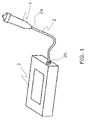
- FIG. 1 is an example of an exhalation measurement device, and shows an exhalation measurement device that measures nitrogen monoxide contained in exhalation, which is correlated to asthma diagnosis.
- the exhalation measurement device in this embodiment comprises a handle component 1 and a measurement device main body 3 that is connected by a tube 2 to the handle component 1.
- the handle component 1 is configured so that the user blows exhalation into the device through the handle component 1.
- One end 2a of the tube 2 is connected to this handle component 1, and the other end 2b of the tube 2 is connected to the measurement device main body 3, which is used to measure the exhalation that is blown in. That is, the handle component 1 is connected to the measurement device main body 3 via the tube 2.
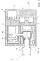
- FIG. 2 shows the configuration of the measurement device main body 3 in the exhalation measurement device in this embodiment.
- the measurement device main body 3 has a flow regulator 4, a chamber 5, inlet/outlet holes 6a and 6b, a sensor 7, a pump 8, a switch valve 18, a main body case 30, and an open channel 60 (see FIGS. 6 to 9 ).
- the flow regulator 4 is provided downstream from the handle component 1, and adjusts the flow of exhalation that is blown in from the handle component 1.
- the chamber 5 is provided downstream from the flow regulator 4, and temporarily holds the exhalation.
- the inlet/outlet holes 6a and 6b are through-holes provided to the chamber 5, and open up the flow regulator 4 to atmospheric pressure.
- the pump 8 is provided downstream from the chamber 5, and sends the exhalation held in the chamber 5 into the sensor 7.
- the switch valve 18 is provided between the chamber 5 and the pump 8, and sends the exhalation that is to be measured to the sensor 7, or sends gas that does not contain any nitrogen monoxide to the sensor 7 in order to initialize the sensor 7.
- the sensor 7 measures the amount of nitrogen monoxide contained in the exhalation that has been adjusted to a specific flow.
- FIG. 3 shows the configuration of the flow regulator in this embodiment.
- the flow regulator 4 which adjusts the flow of exhalation in order to measure the nitrogen monoxide contained in the exhalation, has an exhalation inflow component 9, an exhalation outflow component 10, an adjuster 11, a driver 12, an inflow pressure sensor 13, an outflow pressure sensor 14, and a flow regulator controller 15.
- the exhalation inflow component 9 is connected to the end 2b of the tube 2, and allows exhalation to flow in from the handle component 1 side through the tube 2.
- the exhalation outflow component 10 communicates with the exhalation inflow component 9 via a communicating hole 31, and is connected to the chamber 5.
- the exhalation that flows into the exhalation inflow component 9 flows out of the exhalation outflow component 10 to the chamber 5.
- the exhalation that flows into the flow regulator 4 goes through the exhalation inflow component 9 on the handle component 1 side and the exhalation outflow component 10 on the chamber 5 side, and flows out to the chamber 5.
- the adjuster 11 is disposed along the path between the exhalation inflow component 9 and the exhalation outflow component 10, and adjust the flow of exhalation.
- the driver 12 moves the adjuster 11. More precisely, the adjuster 11 has a valve 32 and a shaft 33.
- the valve 32 is disposed in the exhalation inflow component 9, and is fixed through the communicating hole 31 to the shaft 33 that is disposed substantially perpendicular to the communicating hole 31.
- the shaft 33 is lined to the driver 12, and the driver 12 allows the shaft 33 to move in its axial direction.
- the valve 32 has a disk-shaped first portion 32a and a truncated conical second portion 32b.
- the second portion 32b is provided to the face of the first portion 32a on the communicating hole 31 side.
- the second portion 32b is formed so that its diameter tapers from the exhalation inflow component 9 toward the exhalation outflow component 10.
- the second portion 32b is formed so that its largest diameter is smaller than the diameter of the first portion 32a.
- the shaft 33 is linked to the end of the second portion 32b on the exhalation outflow component 10 side.
- the portion of the first portion 32a that protrudes past the second portion 32b forms a flange 16 on the valve 32.
- the flange 16 hits the wall 17 around the communicating hole 31, causing the communicating hole 31 to be blocked off by the valve 32 and separating the exhalation inflow component 9 and the exhalation outflow component 10.
- the flange 16 has an elastic member 32a1 formed from rubber or another such material on the communicating hole 31 side. This elastic member 32a1 is formed in a ring shape so as to surround the outside of the second portion 32b.
- a protrusion 35 that sticks out from the wall 17 toward the valve 32 is formed on the wall 17 around the communicating hole 31.
- This protrusion 35 is formed in a ring shape so as to surround the communicating hole 31.
- the inflow pressure sensor 13 is disposed on the exhalation inflow component 9 side of the adjuster 11, and senses the pressure in the exhalation inflow component 9.
- the outflow pressure sensor 14 is disposed on the exhalation outflow component 10 side of the adjuster 11, and senses the pressure in the exhalation outflow component 10.
- the flow regulator controller 15 controls the driver 12.
- FIG. 4 is a block diagram of the exhalation measurement device in this embodiment.
- the flow regulator controller 15 has a first offset adjuster 40, a voltage difference detector 41, a determination component 42, and a second offset adjuster 43.
- the first offset adjuster 40 separates the exhalation inflow component 9 from the exhalation outflow component 10 by moving the driver 12 to block off the communicating hole 31 with the valve 32, after which it adjusts the offset of the inflow pressure sensor 13 and the outflow pressure sensor 14 (an example of first offset adjustment).
- the voltage difference detector 41 moves the driver 12 to separate the valve 32 from the wall 17, allowing the exhalation inflow component 9 to communicate with the exhalation outflow component 10.
- the voltage difference detector 41 calculates the difference in output voltage between the inflow pressure sensor 13 and the outflow pressure sensor 14, and detects the output voltage difference.
- the determination component 42 determines whether or not to perform further offset adjustment on the inflow pressure sensor 13 on the basis of the output voltage difference found by the voltage difference detector 41.
- the determination component 42 determines not to perform further offset adjustment if the output voltage difference is substantially 0 (zero).
- the phrase "substantially 0 (zero)" here means that the difference in the output voltage between the inflow pressure sensor 13 and the outflow pressure sensor 14 is within the error range of each.
- the second offset adjuster 43 performs offset adjustment of the inflow pressure sensor 13 using the output voltage difference if the determination component 42 has determined that second offset adjustment is to be performed (an example of second offset adjustment).
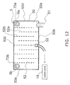
- FIG. 5 is a simplified diagram of the chamber 5.
- FIG. 6 is an external view of the chamber 5, and shows the state when a top plate 62 of the open channel 60 (discussed below) has been removed.
- the chamber 5 has a substantially cuboid container 50 and an inlet 51 from the flow regulator 4 that is formed in this container 50.
- an undulating path 52 from the inlet 51 is formed in the interior of the container 50, and an outlet 53 to the switch valve 18 is formed in the middle portion of the undulating path 52.
- the inlet/outlet holes 6a and 6b are formed on the start and end point sides of the undulating path 52, respectively.
- the configuration of the undulating path 52 inside the chamber 5 is not shown in FIG. 2 .
- the open channel 60 (discussed below) is formed on the upper face of the chamber 5 as shown in FIG. 6 , but in FIG. 5 it is not shown so as to make the internal configuration of the chamber 5 easier to understand.
- the substantially cuboid container 50 has opposing flat faces which are substantially rectangular, and side faces provided in between these flat faces and perpendicular to them.
- the container 50 is fixed to the main body case 30 with one of the opposing flat faces touching the inner side of a face 30a of the main body case 30.
- FIG. 6 of the opposing faces of the container 50, the face that is not touching the face 30a is numbered 50a.
- the main body case 30 is provided so as to house the entire chamber 5, but in FIG. 6 , part of the main body case 30 (the upper portion in FIG. 1 ) is not shown in order to show the appearance of the chamber 5.
- the two that are linked to the long sides of the flat face 50a are numbered 50b and 50c, and the two that are linked to the short sides of the flat face 50a are numbered 50d and 50e.
- the side face 50b and the side face 50c are opposite each other, and the side face 50d and the side face 50e are opposite.
- the undulating path 52 is formed by a plurality of flat walls 52a formed perpendicular to the flat face 50a from the side face 50b toward the side face 50c, and a plurality of flat walls 52b formed perpendicular to the flat face 50a from the side face 50c toward the side face 50b.
- the walls 52a and the walls 52b are disposed alternately from the side face 50d in the direction of the side face 50e.
- the inlet 51 is provided to the end on the side face 50d side of the side face 50b.
- the inlet/outlet holes 6a and 6b are through-holes formed in the flat face 50a. As shown in FIG. 5 , the inlet/outlet hole 6a is provided near the corner of the side face 50c and the side face 50d. To put this another way, the inlet/outlet hole 6a is disposed at a position opposite the inlet 51. The inlet/outlet hole 6b is provided near the corner of the side face 50c and the side face 50e. The outlet 53 is disposed near the center of the long side, on the side face 50b side of the flat face 50a.
- FIG. 7 is a plan view of the open channel 60, and shows the chamber 5 as seen from above in FIG. 6 .
- inlet/outlet holes 30b that connect the interior of the main body case 30 with the exterior are formed in the face 30a.
- the open channel 60 connects the inlet/outlet holes 30b to the inlet/outlet holes 6a and 6b of the chamber 5.
- the open channel 60 has a channel A 601 that links the inlet/outlet hole 6a to two of the four inlet/outlet holes 30b (the right side in FIG. 7 ), and a channel B 602 that links the inlet/outlet hole 6b to the remaining two inlet/outlet holes 30b (the left side in FIG. 7 ).
- the channel A 601 has a first channel 60a that is linked to the inlet/outlet hole 6a, and a third channel 60c that links the first channel 60a and two of the inlet/outlet holes 30b (the right side in FIG. 7 ).
- the channel B 602 has a second channel 60b that is linked to the inlet/outlet hole 6b, and a fourth channel 60d that links the second channel 60b and the remaining two inlet/outlet holes 30b (the left side in FIG. 7 ).
- the first channel 60a and the second channel 60b are formed in the flat face 50a, and the third channel 60c and the fourth channel 60d are formed in the side face 50b.
- the first channel 60a and the second channel 60b are formed by the flat face 50a, a rib 61 provided sticking up from the flat face 50a, and a top plate 62 disposed so as to cover the rib 61.
- the third channel 60c and the fourth channel 60d are formed by the side face 50b, a rib 63 provided sticking up from the side face 50b, and the top plate 64 disposed so as to cover the rib 63.
- the rib 61 and the rib 63 are linked.
- the third channel 60c and the fourth channel 60d are disposed on the side face 50e side of the outlet 53, and are formed substantially perpendicular to the flat face 50a, from the flat face 50a toward the face 30a.
- the first channel 60a has a first portion 60a1 that is formed from the inlet/outlet hole 6a toward the side face 50b, a second portion 60a2 that is formed from the distal end of the first portion 60a1 toward the side face 50e, a third portion 60a3 that is formed from the distal end of the second portion 60a2 toward the side face 50b, and a fourth portion 60a4 that is formed substantially perpendicular to the side face 50b from the distal end of the third portion 60a3 to the third channel 60c, toward the side face 50b.
- the second channel 60b has a first portion 60b1 that is formed from the inlet/outlet hole 6b toward the side face 50d, a second portion 60b2 that is formed doubling back from the distal end of the first portion 60b1 toward the side face 50e, a third portion 60b3 that is formed from the distal end of the second portion 60b2 toward the side face 50b, and a fourth portion 60b4 that is formed from the distal end of the third portion 60b3 to the third channel 60c, toward the side face 50b.
- the open channel 60 is thus formed so that the direction of gas flow changes, any changes in the outside atmosphere are less likely to be transmitted to the exhalation outflow component 10, so fluctuation in the sensing values of the outflow pressure sensor 14 caused by changes in the outside atmosphere can be suppressed.
- FIG. 8 if fluctuation in the exterior pressure or the like causes the pressure in the interior to be higher than the exterior pressure, gas will flow out from the interior of the chamber 5. This state is shown in FIG. 8 .
- the gas that has flowed out of the inlet/outlet hole 6a hits the top plate 62 (the P1 portion in FIG. 8 ), changes direction, and flows into the first portion 60a1.
- the gas flowing through the first portion 60a1 hits the rib 61 (the P2 portion in FIG. 8 ) at the curved portion of the second portion 60a2 from the first portion 60a1, changes direction, and flows into the second portion 60a2.
- the gas that flows through the second portion 60a2 hits the rib 61 (the P3 portion in FIG.
- the gas that has flowed out of the inlet/outlet hole 6b first hits the top plate 62 (the P5 portion in FIG. 8 ), changes direction, and flows into the first portion 60b1.
- the gas that flows through the first portion first portion 60b1 then hits the rib 61 (the P6 portion in FIG. 8 ) at the curved portion of the second portion 60b2 from the first portion 60b1, changes direction, and flows into the second portion 60b2.
- the gas that flows through the second portion 60b2 hits the rib 61 (the P7 portion in FIG. 8 ) at the third portion 60b3, changes direction, and flows into the fourth portion 60b4.
- the gas that has flowed through the fourth portion 60b4 and hit the top plate 64 changes directions, flows through the fourth channel 60d, and is discharged from the inlet/outlet hole 6b to the outside.
- FIG. 9 if the outside pressure increases, for example, gas (air) flows in from the outside.
- gas air
- FIG. 9 The gas that has flowed in from the two inlet/outlet holes 30b on the right side in FIG. 9 flows through the third channel 60c, then hits the top plate 62 (the Q1 portion in FIG. 9 ), changes direction, and flows into the fourth portion 60a4.
- the gas that flows through the fourth portion 60a4 hits the rib 61 (the Q2 portion in FIG. 9 ) at the third portion 60a3, changes direction, and flows into the second portion 60a2.
- the gas that flows through the second portion 60a2 hits the rib 61 (the Q3 portion in FIG.
- the gas that flows through the fourth portion 60b4 then hits the rib 61 (the Q6 portion in FIG. 9 ) at the third portion 60b3, changes direction, and flows into the second portion 60b2.
- the gas that flows through the second portion 60b2 hits the rib 61 (the Q7 portion in FIG. 9 ) at the curved part of the first portion 60b1 and the second portion 60b2, changes direction, and flows into the first portion 60b1.
- the gas that flows through the first portion 60b1 and hits the rib 61 (the Q8 portion in FIG. 9 ) then changes direction and flows into the inlet/outlet hole 6b.
- FIGS. 8 and 9 only the main portions out of the portions where the gas hits and changes direction are discussed, but actually the gas hits all of the portions in the channel.
- the gas that has hit the P4 portion flows into the inlet/outlet holes 30b while in contact with the Q1 portion shown in FIG. 9 .
- the gas that has hit the Q4 portion flows into the inlet/outlet hole 6a while in contact with the P1 portion shown in FIG. 8 .
- wall portions (such as the P1, P4, Q1, and Q4 portions) that make up the open channel 60 are formed at least at positions opposite the inlet/outlet holes 6a and 6b, or at positions opposite the inlet/outlet holes 30b. Therefore, when gas moves from the inlet/outlet holes 6a and 6b toward the inlet/outlet holes 30b, or when gas moves from the inlet/outlet holes 30b toward the inlet/outlet holes 6a and 6b, the gas will hit these walls and the direction of its flow will be greatly changed, so any external effect can be prevented from directly affecting the interior of the chamber 5.
- the exhalation measurement device in this embodiment comprises a controller 44 that controls the switch valve 18, the pump 8, and the sensor 7.
- This controller 44 is connected to the flow regulator controller 15, and controls the switch valve 18 by receiving signals from the first offset adjuster 40, for example.
- FIG. 10 is a flowchart of the control operation in zero point correction of the exhalation measurement device in this embodiment.
- the first offset adjuster 40 of the flow regulator controller 15 uses the above-mentioned trigger to move the adjuster 11 prior to measuring the nitrogen monoxide content in the exhalation, which causes the flange 16 of the adjuster 11 to hit the wall 17 formed between the exhalation inflow component 9 and the exhalation outflow component 10. This puts the exhalation inflow component 9 and the exhalation outflow component 10 into a separated state.
- the linking path of the chamber 5 and the sensor 7 (pump 8) is temporarily blocked off by the switch valve 18 (S2).
- S2 a movement completion signal is sent from the first offset adjuster 40 to the controller 44 upon completion of the movement of the adjuster 11 in S1, and the controller 44 controls the blocking produced by the switch valve 18.
- the first offset adjuster 40 uses the inflow pressure sensor 13 and the outflow pressure sensor 14 to measure the pressure of the exhalation inflow component 9 and the exhalation outflow component 10 in a state in which the exhalation inflow component 9 and the exhalation outflow component 10 have been separated, these first measurement results are outputted to the first offset adjuster 40, and offset adjustment of the inflow pressure sensor 13 and the outflow pressure sensor 14 is performed (S3 to S6).
- the inlet/outlet holes 6a and 6b that open up to atmospheric pressure are provided to the chamber 5 linked to the exhalation outflow component 10 in order to keep the pressure constant in the interior. Since the linking path in the direction of the sensor 7 (the pump 8) is blocked off by the switch valve 18 disposed downstream from the chamber 5, the exhalation outflow component 10 and the chamber 5 are at atmospheric pressure.
- the pressure of the exhalation outflow component 10 is measured, this measurement result is outputted to the first offset adjuster 40 (S3), and the first offset adjuster 40 performs offset adjustment on the outflow pressure sensor 14 on the basis of the outputted measurement result (S4).
- the pressure of the exhalation inflow component 9 is measured, this measurement result is outputted to the first offset adjuster 40 (S5), and the first offset adjuster 40 performs offset adjustment on the inflow pressure sensor 13 on the basis of the outputted measurement result (S6).
- the voltage difference detector 41 moves the adjuster 11 to create a state in which the exhalation inflow component 9 and the exhalation outflow component 10 are coupled (also called “linked") (S7).
- the inflow pressure sensor 13 and the outflow pressure sensor 14 are used to measure the pressure of the exhalation inflow component 9 and the exhalation outflow component 10, and the second measurement result is outputted to the voltage difference detector 41 (S8 and S9).
- the above-mentioned first measurement result and second measurement result are used to perform zero point correction on the inflow pressure sensor 13 and the outflow pressure sensor 14.
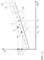
- the line 19 shows the reference characteristics of a pressure sensor
- 20 is the offset range.
- the term “reference characteristics” here means the output voltage theoretically outputted by the pressure sensor under a specific known pressure environment
- offset range means the variance width over which the pressure sensor outputs its output voltage under a specific known pressure environment.
- the inflow pressure sensor 13 and the outflow pressure sensor 14 are the same type of pressure sensor, having the reference characteristics (line 19) and offset range 20 shown in FIG. 11, and FIG. 11 will be used to describe zero point correction of the inflow pressure sensor 13 and the outflow pressure sensor 14.
- the pressure of the exhalation outflow component 10 is measured by the outflow pressure sensor 14 (S3).
- the pressure of the exhalation outflow component 10 here is atmospheric pressure (P 0 ), so the output voltage is supposed to be outputted as V 0 (point z) from the reference characteristics of the outflow pressure sensor 14. Nevertheless, the actual measured value is outputted as an output voltage V 1 (point a).
- the characteristics of the outflow pressure sensor 14 are indicated by the line 19'.
- the characteristics of the outflow pressure sensor 14 can be matched to the reference characteristics (line 19) by moving an intercept by (V 0 - V 1 ) in a state in which the slope is the same with respect to the line 19'.
- the pressure of the exhalation inflow component 9 is measured by the inflow pressure sensor 13 in a state in which the exhalation inflow component 9 and the exhalation outflow component 10 have been separated (S5).
- the exhalation inflow component 9 is linked to the handle component 1, which has an inlet that is always open and is used to blow in exhalation. Therefore, unlike with the exhalation outflow component 10, the pressure (P x ) of the exhalation inflow component 9 is uncertain.
- the pressure of the exhalation inflow component 9 is measured using the inflow pressure sensor 13 under this pressure environment (P x ), and as a result the output voltage is V 2 (point b).
- the output voltage V 2 is assumed to be a value when the pressure is under an atmospheric pressure (P 0 ) environment, and offset adjustment is performed so that the output voltage V 0 is outputted instead of the output voltage V 2 (S6).
- the inflow pressure sensor 13 and the outflow pressure sensor 14 are used to measure the pressure of the exhalation inflow component 9 and the exhalation outflow component 10 in a state in which the exhalation inflow component 9 and the exhalation outflow component 10 have been separated (S3 and S5), and offset adjustment is performed so that the output voltage V 0 is outputted instead of the output voltage V 1 and the output voltage V 2 (S4 and S6) (an example of first offset adjustment).
- the voltage difference detector 41 moves the adjuster 11 to create a state in which the exhalation inflow component 9 and the exhalation outflow component 10 are coupled (also called “communicating") (S7).
- the inflow pressure sensor 13 and the outflow pressure sensor 14 are used to measure the pressure of the exhalation inflow component 9 and the exhalation outflow component 10 (S8 and S9).
- the exhalation inflow component 9 and exhalation outflow component 10 are in a coupled state, they have the same pressure value, and this pressure value is shown in FIG. 11 as P 1 .
- the proper offset adjustment is performed on the outflow pressure sensor 14 in S4, so the output voltage that is outputted by the outflow pressure sensor 14 in S8 is V 3 (the point c) from the reference characteristics (the line 19), as shown in FIG. 11 .
- the output voltage that is outputted by the inflow pressure sensor 13 in S9 is assumed to be a value at which the output voltage (V 2 ) is under an atmospheric pressure (P 0 ) environment, and first offset adjustment is performed, so it is unclear whether or not it is outputted as the output voltage V 3 .
- the voltage difference detector 41 finds the difference between the output voltage (Vs) of the inflow pressure sensor 13 obtained in S9 and the output voltage (V 3 ) of the outflow pressure sensor 14 obtained in S8 (S10).
- the determination component 42 determines whether or not the output voltage difference (Vs - V 3 ) found in S10 is substantially 0 (zero) (S11). Specifically, it is determined whether or not the output voltage (Vs) of the inflow pressure sensor 13 is substantially the same as the output voltage (V 3 ) of the outflow pressure sensor 14 (S11).
- the output voltage (Vs) of the inflow pressure sensor 13 need only be substantially the same as the output voltage (V 3 ) of the outflow pressure sensor 14, and need not be exactly the same.
- the terms “substantially the same” and “substantially 0 (zero)” may refer to a permissible range that varies with the specifications of the device and the error range of the output voltage.
- the first offset adjustment of the inflow pressure sensor 13 can be concluded to have been performed so as to obtain the reference characteristics (the line 19), just as with the outflow pressure sensor 14.
- the pressure of the exhalation inflow component 9 in a state in which the exhalation inflow component 9 and the exhalation outflow component 10 have been separated can be concluded to be atmospheric pressure (P 0 ). That is, the inflow pressure sensor 13 completes correction to the reference characteristics (the line 19) by means of first offset adjustment, and control of the zero point correction is ended.
- the output voltage (Vs) of the inflow pressure sensor 13 is not outputted as the output voltage (V 3 ), but as V 4 , the pressure (Px) of the exhalation inflow component 9 in a state in which the exhalation inflow component 9 and the exhalation outflow component 10 have been separated can be concluded not to be atmospheric pressure (P 0 ). That is, correction to the reference characteristics (the line 19) of the inflow pressure sensor 13 is not completed with first offset adjustment.
- second offset adjustment is performed using the difference between the output voltage (V 4 ) of the inflow pressure sensor 13 and the output voltage (V 3 ) of the outflow pressure sensor 14, and correction to the reference characteristics (the line 19) of the inflow pressure sensor 13 is completed (S12).
- correction to the reference characteristics can be completed by further subjecting the inflow pressure sensor 13 to offset adjustment following the first offset adjustment, according to the difference between the output voltage (V 4 ) and the output voltage (V 3 ).
- the output voltage of the outflow pressure sensor 14 at this pressure value (P 1 ) is V 3 .
- the output voltage of the inflow pressure sensor 13 is V 4 .
- the inflow pressure sensor 13 and the outflow pressure sensor 14 are used to measure the pressure of the exhalation inflow component 9 and the exhalation outflow component 10, and if the result of comparing the output voltage Vs and the output voltage V 3 is that they are the same (if the output voltage Vs is substantially V 3 ), then the state of the first offset adjustment is maintained, but if the comparison results are different (if the output voltage Vs is V 4 ), then further offset adjustment (second offset adjustment) is performed using the difference between the above-mentioned output voltage (V 4 ) and the output voltage (V 3 ) with respect to the characteristics after the first offset adjustment was performed.
- first offset adjustment is performed, and second offset adjustment is performed using the difference in the output voltages between the exhalation inflow component 9 and the exhalation outflow component 10, even if there is a change over time, zero point correction of the inflow pressure sensor 13 and the outflow pressure sensor 14 will always be possible under an atmospheric pressure environment during measurement, the effect of changes over time can be suppressed, and the flow established as a guideline can be accurately controlled.
- the exhalation measurement device in the above embodiment comprises the handle component 1, the flow regulator 4, the chamber 5, the inlet/outlet holes 6a and 6b (an example of first through-holes), the sensor 7 (an example of a measurement component), and the pump 8. Exhalation is blown into the handle component 1.
- the flow regulator 4 is provided downstream from the handle component 1 and adjusts the flow of exhalation blown in from the handle component 1.
- the chamber 5 is provided downstream from the flow regulator 4 and temporarily stores exhalation.
- the inlet/outlet holes 6a and 6b are provided to the chamber 5 and opens up the flow regulator 4 to atmospheric pressure.
- the sensor 7 measures a specific component in exhalation.
- the pump 8 is provided downstream from the chamber 5 and sends exhalation into the sensor 7.
- the flow regulator 4 has the exhalation inflow component 9, the exhalation outflow component 10, the adjuster 11 (an example of a flow adjuster), the driver 12, the inflow pressure sensor 13, the outflow pressure sensor 14, the first offset adjuster 40, the voltage difference detector 41, and the second offset adjuster 43.
- the exhalation inflow component 9 is where exhalation flows in from the handle component 1 side.
- the exhalation outflow component 10 is where exhalation flows out to the chamber 5 side.
- the adjuster 11 is provided between the exhalation inflow component 9 and the exhalation outflow component 10 and adjusts the flow of exhalation.
- the driver 12 moves the flow adjuster 11.
- the inflow pressure sensor 13 senses the pressure of the exhalation inflow component 9.
- the outflow pressure sensor 14 senses the pressure of the exhalation inflow component 10.
- the first offset adjuster 40 causes the driver 12 to move the flow adjuster 11 and create a separated state between the exhalation inflow component 9 and the exhalation outflow component 10, and performs first offset adjustment of the inflow pressure sensor 13 and the outflow pressure sensor 14.
- the voltage difference detector 41 causes the driver to move the flow adjuster 11 and create a linked state between the exhalation inflow component 9 and the exhalation outflow component 10, and detects the output voltage difference after the first offset adjustment of the inflow pressure sensor 13 and the outflow pressure sensor 14.
- the second offset adjuster 43 uses the output voltage difference to perform second offset adjustment of the inflow pressure sensor 13.
- second offset adjustment is performed using the difference in output voltage between the inflow pressure sensor 13 and the outflow pressure sensor 14.
- second offset adjustment since the exhalation inflow component 9 and the exhalation outflow component 10 are linked, they are both at the same pressure. Therefore, second offset adjustment of the inflow pressure sensor 13 can be performed on the basis of the value of the outflow pressure sensor 14 that has undergone suitable zero point correction in the first offset adjustment.
- the exhalation outflow component 10 in a separated state is under an atmospheric pressure environment, and the first offset adjuster 40 performs first offset adjustment so that the value sensed by the outflow pressure sensor 14 is atmospheric pressure.
- zero point correction of the outflow pressure sensor 14 can be performed using atmospheric pressure as a reference. Therefore, in second offset adjustment, zero point correction of the inflow pressure sensor 13 can be performed using the corrected outflow pressure sensor 14 as a reference.
- the first offset adjuster 40 performs first offset adjustment so that the value sensed by the inflow pressure sensor 13 indicates atmospheric pressure, assuming that the exhalation inflow component 9 in a separated state is under an atmospheric pressure environment.
- the flow regulator 4 further has the determination component 42, which determines whether or not to perform second offset adjustment with the second offset adjuster 43.
- the determination component 42 determines not to perform second offset adjustment of the inflow pressure sensor 13 if the output voltage difference is substantially 0 (zero).
- the exhalation measurement device in the above embodiment further comprises the main body case 30 and the open channel 60.
- the main body case 30 accommodates the flow regulator 4, the chamber 5, the sensor 7, and the pump 8, and has the inlet/outlet holes 30b (an example of second through-holes) that connect the inside and outside.
- the channel A 601 that links the inlet/outlet holes 30b with the inlet/outlet hole 6a of the open channel 60 constitutes part of the channel, connects the inlet/outlet holes 30b to the inlet/outlet hole 6a, and has a P1 portion and a Q1 portion (examples of first channel wall) that are opposite the inlet/outlet hole 6a and/or the inlet/outlet holes 30b.
- the channel B 602 that links the inlet/outlet holes 30b with the inlet/outlet hole 6b of the open channel 60 constitutes part of the channel, connects the inlet/outlet hole 6b and the inlet/outlet holes 30b, and has a P5 portion and a Q5 portion (examples of first channel wall) that are opposite the inlet/outlet hole 6b and/or the inlet/outlet holes 30b.
- the open channel 60 is formed three-dimensionally as shown in FIGS. 6 to 9 .
- the first channel 60a and the second channel 60b are formed so that the orientation of the channel changes in the XY direction (two-dimensionally) on the flat face 50a of the chamber 5, and the third channel 60c and the fourth channel 60d are formed in a direction perpendicular to the flat face 50a (the Z direction).
- varying the orientation of the channel three-dimensionally means that a gas flowing between the inlet/outlet holes 6a and 6b and the inlet/outlet holes 30b will have to change directions when it hits the channel walls a number of times, so fluctuation of a gas outside the main body case 30 will be less likely to be directly transmitted into the interior of the chamber 5.
- the channel A 601 that links the inlet/outlet holes 30b with the inlet/outlet hole 6a of the open channel 60 constitutes part of a channel, and further has the P2 portion, the P3 portion, the P4 portion, the Q2 portion, the Q3 portion, and the Q4 portion (examples of second channel wall) disposed so as to change the flow direction of the gas.
- An example of these second channel walls is for them to be disposed substantially perpendicular to the P1 portion and the Q1 portion (examples of first channel wall).
- the channel B 602 that links the inlet/outlet holes 30b with the inlet/outlet hole 6b of the open channel 60 constitutes part of a channel, and further has the P6 portion, the P7 portion, the P8 portion, the Q6 portion, the Q7 portion, and the Q8 portion (examples of second channel wall) disposed so as to change the flow direction of the gas.
- An example of these second channel walls is for them to be disposed substantially perpendicular to the P5 portion and the Q5 portion (examples of first channel wall).
- the flow regulator 4 has the wall 17 and the communicating hole 31.
- the wall 17 is provided between the exhalation inflow component 9 and the exhalation outflow component 10.
- the communicating hole 31 is formed in the wall 17, and allows the exhalation inflow component 9 to communicate with the exhalation outflow component 10.
- the adjuster 11 has the valve 32 that is able to open and close the communicating hole 31, and the shaft 33 that is fixed to the valve 32 and is driven by the driver 12.
- the valve 32 has the elastic member 32a1 that hits the wall 17 around the communicating hole 31 when the communicating hole 31 is closed.
- valve 32 When the valve 32 thus has the elastic member 32a1, it tends to fit snugly against the wall 17, so the communicating hole 31 can be more reliably blocked off by the valve 32.
- the flow regulator 4 further has the ring-shaped protrusion 35 that protrudes from the wall 17 so as to surround the communicating hole 31.
- the elastic member 32a1 hits the protrusion 35 in a state in which the communicating hole 31 has been closed by the valve 32.
- the method for controlling the exhalation measurement device in the above embodiment is a method for controlling an exhalation measurement device comprising the handle component 1 into which a user exhales, the flow regulator 4 that is provided downstream from the handle component 1 and adjusts the flow of exhalation blown in from the handle component 1, the chamber 5 that is provided downstream from the flow regulator 4 and temporarily stores exhalation, the inlet/outlet holes 6a and 6b that are provided to the chamber 5 and open up the flow regulator 4 to atmospheric pressure, the sensor 7 that measures a specific component in exhalation, and the pump 8 that is provided downstream from the chamber 5 and sends exhalation into the sensor 7, wherein said method comprises steps S1 to S6 (an example of first offset adjustment steps), steps S7 to S10 (an example of pressure differential detecting steps), and step S12 (an example of a second offset adjustment step), as shown in FIG. 8 .
- steps S1 to S6 an example of first offset adjustment steps
- steps S7 to S10 an example of pressure differential detecting steps
- step S12 an example of
- the difference in output voltage between the inflow pressure sensor 13 and the outflow pressure sensor 14 is used to perform second offset adjustment, so even if there are changes over time, zero point correction of the inflow pressure sensor 13 and the outflow pressure sensor 14 will always be possible under an atmospheric pressure environment during measurement, the effect of changes over time can be suppressed, and the flow established as a guideline can be accurately controlled.
- the method for controlling an exhalation measurement device in the above embodiment further comprises a step S11 (an example of a determination step) of determining whether or not to perform second offset adjustment on the basis of the output voltage difference.
- control can be performed so that it is not executed.
- the exhalation measurement device and its control method of the present invention have the effect of allowing accurate zero point correction to be performed even if turbulence occurs, and are expected to find application in the zero point correction of the flow adjusting pressure sensors of flow regulators provided to exhalation measurement devices that are used in checking pulmonary function, diagnosing asthma, and so forth.
Landscapes
- Health & Medical Sciences (AREA)
- Life Sciences & Earth Sciences (AREA)
- Engineering & Computer Science (AREA)
- Pulmonology (AREA)
- Public Health (AREA)
- Medical Informatics (AREA)
- Veterinary Medicine (AREA)
- Physics & Mathematics (AREA)
- General Health & Medical Sciences (AREA)
- Biophysics (AREA)
- Pathology (AREA)
- Biomedical Technology (AREA)
- Heart & Thoracic Surgery (AREA)
- Physiology (AREA)
- Molecular Biology (AREA)
- Surgery (AREA)
- Animal Behavior & Ethology (AREA)
- Signal Processing (AREA)
- Computer Vision & Pattern Recognition (AREA)
- Artificial Intelligence (AREA)
- Psychiatry (AREA)
- Investigating Or Analysing Biological Materials (AREA)
- Measurement Of The Respiration, Hearing Ability, Form, And Blood Characteristics Of Living Organisms (AREA)
- Sampling And Sample Adjustment (AREA)
Applications Claiming Priority (2)
| Application Number | Priority Date | Filing Date | Title |
|---|---|---|---|
| JP2013109122 | 2013-05-23 | ||
| PCT/JP2014/002676 WO2014188720A1 (ja) | 2013-05-23 | 2014-05-21 | 呼気測定装置及びその制御方法 |
Publications (3)
| Publication Number | Publication Date |
|---|---|
| EP3000393A1 true EP3000393A1 (de) | 2016-03-30 |
| EP3000393A4 EP3000393A4 (de) | 2016-07-13 |
| EP3000393B1 EP3000393B1 (de) | 2017-02-15 |
Family
ID=51933287
Family Applications (1)
| Application Number | Title | Priority Date | Filing Date |
|---|---|---|---|
| EP14800932.7A Active EP3000393B1 (de) | 2013-05-23 | 2014-05-21 | Exhalationsmessvorrichtung und steuerungsverfahren dafür |
Country Status (4)
| Country | Link |
|---|---|
| US (1) | US9931058B2 (de) |
| EP (1) | EP3000393B1 (de) |
| JP (1) | JP6290197B2 (de) |
| WO (1) | WO2014188720A1 (de) |
Families Citing this family (4)
| Publication number | Priority date | Publication date | Assignee | Title |
|---|---|---|---|---|
| CN106062558B (zh) * | 2014-03-26 | 2019-01-25 | 普和希控股公司 | 呼出气体测量装置及呼出气体测量装置的控制方法 |
| CA2850998A1 (en) * | 2014-04-18 | 2015-10-18 | Thc Breathalyzer, Inc. | Cannabis drug detection device |
| PL131948U1 (pl) * | 2024-01-31 | 2024-07-15 | Advanced Medical Equipment Spółka Akcyjna | Układ prowadzenia płynu |
| PL447655A1 (pl) * | 2024-01-31 | 2024-07-15 | Advanced Medical Equipment Spółka Akcyjna | Urządzenie do pomiaru oddechu oraz układ prowadzenia płynu |
Family Cites Families (6)
| Publication number | Priority date | Publication date | Assignee | Title |
|---|---|---|---|---|
| JP4082901B2 (ja) * | 2001-12-28 | 2008-04-30 | 忠弘 大見 | 圧力センサ、圧力制御装置及び圧力式流量制御装置の温度ドリフト補正装置 |
| ES2221596T3 (es) * | 2002-09-16 | 2007-01-01 | Aerocrine Ab | Aparato para analisis de gas para diagnostico. |
| JP3863505B2 (ja) | 2003-06-20 | 2006-12-27 | 忠弘 大見 | 圧力センサ及び圧力制御装置並びに圧力式流量制御装置の自動零点補正装置 |
| US9763600B2 (en) | 2010-02-17 | 2017-09-19 | Koninklijke Philips N.V. | Nitric oxide measurement method and apparatus |
| JPWO2012127794A1 (ja) | 2011-03-18 | 2014-07-24 | パナソニックヘルスケア株式会社 | 窒素酸化物濃度測定装置 |
| CA2871175C (en) | 2012-04-24 | 2019-07-02 | Panasonic Healthcare Co., Ltd. | Handle device and breath analysis device |
-
2014
- 2014-05-21 WO PCT/JP2014/002676 patent/WO2014188720A1/ja not_active Ceased
- 2014-05-21 US US14/891,964 patent/US9931058B2/en active Active
- 2014-05-21 JP JP2015518081A patent/JP6290197B2/ja active Active
- 2014-05-21 EP EP14800932.7A patent/EP3000393B1/de active Active
Also Published As
| Publication number | Publication date |
|---|---|
| US20160089058A1 (en) | 2016-03-31 |
| US9931058B2 (en) | 2018-04-03 |
| JPWO2014188720A1 (ja) | 2017-02-23 |
| WO2014188720A1 (ja) | 2014-11-27 |
| JP6290197B2 (ja) | 2018-03-07 |
| EP3000393B1 (de) | 2017-02-15 |
| EP3000393A4 (de) | 2016-07-13 |
Similar Documents
| Publication | Publication Date | Title |
|---|---|---|
| EP3000393B1 (de) | Exhalationsmessvorrichtung und steuerungsverfahren dafür | |
| US9870006B2 (en) | Pressure type flow control system with flow monitoring | |
| JP7041697B2 (ja) | チャンバ圧力制御方法及び装置、半導体設備 | |
| EP2236174B1 (de) | Beatmungsgerät | |
| US20130092258A1 (en) | Flow rate control device, and diagnostic device and recording medium recorded with diagnostic program used for flow rate control device | |
| US20080257350A1 (en) | Respirator and method for calibrating flow rate measuring component thereof | |
| US20150241264A1 (en) | Self-Calibrating Mechanism and Self-Calibrating Method for Flow Rate Sensor, and Diagnostic Mechanism and Diagnostic Method for Fluid Sensor | |
| JP6498087B2 (ja) | 測定装置 | |
| KR20150060788A (ko) | 압력 기초 질량 유량 제어기의 자기 증명을 위한 방법 및 장치 | |
| US11786693B2 (en) | Device with an inhalation valve for a ventilation system | |
| KR20160132404A (ko) | 질량 유량 컨트롤러를 통해 유동을 모니터링하는 시스템 및 방법 | |
| US8931482B2 (en) | Breathing apparatus with compensation of the ambient pressure | |
| KR101407978B1 (ko) | 방폭 설비용 공기압 유지 시스템 | |
| KR102502013B1 (ko) | 질량 유량 제어 장치 및 이의 제어방법 | |
| CN103125012A (zh) | 基板处理系统 | |
| US20250249202A1 (en) | Gas valve for ventilation, a circuit for a ventilation system and a method for determining a releasing gas flow | |
| US8412358B2 (en) | Method and device for testing drive parameters of an electropneumatic valve for a pneumatic actuating drive | |
| TWI696808B (zh) | 測定裝置 | |
| US11083859B2 (en) | Respirator and method for determining a fresh gas flow | |
| US20180266865A1 (en) | Diagnostic system, diagnostic method, diagnostic program, and flow rate controller | |
| US20210405667A1 (en) | Mass flow control system, and semiconductor manufacturing equipment and vaporizer including the system | |
| CN108627306A (zh) | 检测气路气密性的装置和方法 | |
| US11193813B2 (en) | Dosing and weighing device and method for determining the weight of a product in a dosing and weighing device | |
| JP6498541B2 (ja) | 測定装置 | |
| CN203323981U (zh) | 气体泄漏测量仪 |
Legal Events
| Date | Code | Title | Description |
|---|---|---|---|
| PUAI | Public reference made under article 153(3) epc to a published international application that has entered the european phase |
Free format text: ORIGINAL CODE: 0009012 |
|
| 17P | Request for examination filed |
Effective date: 20151123 |
|
| AK | Designated contracting states |
Kind code of ref document: A1 Designated state(s): AL AT BE BG CH CY CZ DE DK EE ES FI FR GB GR HR HU IE IS IT LI LT LU LV MC MK MT NL NO PL PT RO RS SE SI SK SM TR |
|
| AX | Request for extension of the european patent |
Extension state: BA ME |
|
| A4 | Supplementary search report drawn up and despatched |
Effective date: 20160609 |
|
| RIC1 | Information provided on ipc code assigned before grant |
Ipc: G01N 1/02 20060101ALI20160603BHEP Ipc: G01N 33/497 20060101ALI20160603BHEP Ipc: A61B 5/097 20060101AFI20160603BHEP Ipc: G01N 33/48 20060101ALI20160603BHEP |
|
| DAX | Request for extension of the european patent (deleted) | ||
| GRAP | Despatch of communication of intention to grant a patent |
Free format text: ORIGINAL CODE: EPIDOSNIGR1 |
|
| INTG | Intention to grant announced |
Effective date: 20160923 |
|
| GRAS | Grant fee paid |
Free format text: ORIGINAL CODE: EPIDOSNIGR3 |
|
| GRAA | (expected) grant |
Free format text: ORIGINAL CODE: 0009210 |
|
| AK | Designated contracting states |
Kind code of ref document: B1 Designated state(s): AL AT BE BG CH CY CZ DE DK EE ES FI FR GB GR HR HU IE IS IT LI LT LU LV MC MK MT NL NO PL PT RO RS SE SI SK SM TR |
|
| REG | Reference to a national code |
Ref country code: CH Ref legal event code: EP Ref country code: GB Ref legal event code: FG4D |
|
| REG | Reference to a national code |
Ref country code: IE Ref legal event code: FG4D |
|
| REG | Reference to a national code |
Ref country code: AT Ref legal event code: REF Ref document number: 867445 Country of ref document: AT Kind code of ref document: T Effective date: 20170315 |
|
| REG | Reference to a national code |
Ref country code: DE Ref legal event code: R096 Ref document number: 602014006832 Country of ref document: DE |
|
| REG | Reference to a national code |
Ref country code: NL Ref legal event code: MP Effective date: 20170215 |
|
| REG | Reference to a national code |
Ref country code: LT Ref legal event code: MG4D |
|
| REG | Reference to a national code |
Ref country code: AT Ref legal event code: MK05 Ref document number: 867445 Country of ref document: AT Kind code of ref document: T Effective date: 20170215 |
|
| PG25 | Lapsed in a contracting state [announced via postgrant information from national office to epo] |
Ref country code: HR Free format text: LAPSE BECAUSE OF FAILURE TO SUBMIT A TRANSLATION OF THE DESCRIPTION OR TO PAY THE FEE WITHIN THE PRESCRIBED TIME-LIMIT Effective date: 20170215 Ref country code: LT Free format text: LAPSE BECAUSE OF FAILURE TO SUBMIT A TRANSLATION OF THE DESCRIPTION OR TO PAY THE FEE WITHIN THE PRESCRIBED TIME-LIMIT Effective date: 20170215 Ref country code: NO Free format text: LAPSE BECAUSE OF FAILURE TO SUBMIT A TRANSLATION OF THE DESCRIPTION OR TO PAY THE FEE WITHIN THE PRESCRIBED TIME-LIMIT Effective date: 20170515 Ref country code: GR Free format text: LAPSE BECAUSE OF FAILURE TO SUBMIT A TRANSLATION OF THE DESCRIPTION OR TO PAY THE FEE WITHIN THE PRESCRIBED TIME-LIMIT Effective date: 20170516 Ref country code: FI Free format text: LAPSE BECAUSE OF FAILURE TO SUBMIT A TRANSLATION OF THE DESCRIPTION OR TO PAY THE FEE WITHIN THE PRESCRIBED TIME-LIMIT Effective date: 20170215 |
|
| PG25 | Lapsed in a contracting state [announced via postgrant information from national office to epo] |
Ref country code: AT Free format text: LAPSE BECAUSE OF FAILURE TO SUBMIT A TRANSLATION OF THE DESCRIPTION OR TO PAY THE FEE WITHIN THE PRESCRIBED TIME-LIMIT Effective date: 20170215 Ref country code: SE Free format text: LAPSE BECAUSE OF FAILURE TO SUBMIT A TRANSLATION OF THE DESCRIPTION OR TO PAY THE FEE WITHIN THE PRESCRIBED TIME-LIMIT Effective date: 20170215 Ref country code: PT Free format text: LAPSE BECAUSE OF FAILURE TO SUBMIT A TRANSLATION OF THE DESCRIPTION OR TO PAY THE FEE WITHIN THE PRESCRIBED TIME-LIMIT Effective date: 20170615 Ref country code: BG Free format text: LAPSE BECAUSE OF FAILURE TO SUBMIT A TRANSLATION OF THE DESCRIPTION OR TO PAY THE FEE WITHIN THE PRESCRIBED TIME-LIMIT Effective date: 20170515 Ref country code: ES Free format text: LAPSE BECAUSE OF FAILURE TO SUBMIT A TRANSLATION OF THE DESCRIPTION OR TO PAY THE FEE WITHIN THE PRESCRIBED TIME-LIMIT Effective date: 20170215 Ref country code: NL Free format text: LAPSE BECAUSE OF NON-PAYMENT OF DUE FEES Effective date: 20170215 Ref country code: LV Free format text: LAPSE BECAUSE OF FAILURE TO SUBMIT A TRANSLATION OF THE DESCRIPTION OR TO PAY THE FEE WITHIN THE PRESCRIBED TIME-LIMIT Effective date: 20170215 Ref country code: RS Free format text: LAPSE BECAUSE OF FAILURE TO SUBMIT A TRANSLATION OF THE DESCRIPTION OR TO PAY THE FEE WITHIN THE PRESCRIBED TIME-LIMIT Effective date: 20170215 Ref country code: LU Free format text: LAPSE BECAUSE OF NON-PAYMENT OF DUE FEES Effective date: 20170531 |
|
| PG25 | Lapsed in a contracting state [announced via postgrant information from national office to epo] |
Ref country code: IT Free format text: LAPSE BECAUSE OF FAILURE TO SUBMIT A TRANSLATION OF THE DESCRIPTION OR TO PAY THE FEE WITHIN THE PRESCRIBED TIME-LIMIT Effective date: 20170215 Ref country code: CZ Free format text: LAPSE BECAUSE OF FAILURE TO SUBMIT A TRANSLATION OF THE DESCRIPTION OR TO PAY THE FEE WITHIN THE PRESCRIBED TIME-LIMIT Effective date: 20170215 Ref country code: RO Free format text: LAPSE BECAUSE OF FAILURE TO SUBMIT A TRANSLATION OF THE DESCRIPTION OR TO PAY THE FEE WITHIN THE PRESCRIBED TIME-LIMIT Effective date: 20170215 Ref country code: EE Free format text: LAPSE BECAUSE OF FAILURE TO SUBMIT A TRANSLATION OF THE DESCRIPTION OR TO PAY THE FEE WITHIN THE PRESCRIBED TIME-LIMIT Effective date: 20170215 Ref country code: SK Free format text: LAPSE BECAUSE OF FAILURE TO SUBMIT A TRANSLATION OF THE DESCRIPTION OR TO PAY THE FEE WITHIN THE PRESCRIBED TIME-LIMIT Effective date: 20170215 |
|
| REG | Reference to a national code |
Ref country code: DE Ref legal event code: R097 Ref document number: 602014006832 Country of ref document: DE |
|
| PG25 | Lapsed in a contracting state [announced via postgrant information from national office to epo] |
Ref country code: DK Free format text: LAPSE BECAUSE OF FAILURE TO SUBMIT A TRANSLATION OF THE DESCRIPTION OR TO PAY THE FEE WITHIN THE PRESCRIBED TIME-LIMIT Effective date: 20170215 Ref country code: SM Free format text: LAPSE BECAUSE OF FAILURE TO SUBMIT A TRANSLATION OF THE DESCRIPTION OR TO PAY THE FEE WITHIN THE PRESCRIBED TIME-LIMIT Effective date: 20170215 Ref country code: PL Free format text: LAPSE BECAUSE OF FAILURE TO SUBMIT A TRANSLATION OF THE DESCRIPTION OR TO PAY THE FEE WITHIN THE PRESCRIBED TIME-LIMIT Effective date: 20170215 |
|
| PLBE | No opposition filed within time limit |
Free format text: ORIGINAL CODE: 0009261 |
|
| STAA | Information on the status of an ep patent application or granted ep patent |
Free format text: STATUS: NO OPPOSITION FILED WITHIN TIME LIMIT |
|
| REG | Reference to a national code |
Ref country code: CH Ref legal event code: PL |
|
| 26N | No opposition filed |
Effective date: 20171116 |
|
| PG25 | Lapsed in a contracting state [announced via postgrant information from national office to epo] |
Ref country code: MC Free format text: LAPSE BECAUSE OF FAILURE TO SUBMIT A TRANSLATION OF THE DESCRIPTION OR TO PAY THE FEE WITHIN THE PRESCRIBED TIME-LIMIT Effective date: 20170215 |
|
| REG | Reference to a national code |
Ref country code: IE Ref legal event code: MM4A |
|
| PG25 | Lapsed in a contracting state [announced via postgrant information from national office to epo] |
Ref country code: SI Free format text: LAPSE BECAUSE OF FAILURE TO SUBMIT A TRANSLATION OF THE DESCRIPTION OR TO PAY THE FEE WITHIN THE PRESCRIBED TIME-LIMIT Effective date: 20170215 Ref country code: LI Free format text: LAPSE BECAUSE OF NON-PAYMENT OF DUE FEES Effective date: 20170531 Ref country code: CH Free format text: LAPSE BECAUSE OF NON-PAYMENT OF DUE FEES Effective date: 20170531 |
|
| REG | Reference to a national code |
Ref country code: FR Ref legal event code: ST Effective date: 20180131 |
|
| PG25 | Lapsed in a contracting state [announced via postgrant information from national office to epo] |
Ref country code: LU Free format text: LAPSE BECAUSE OF NON-PAYMENT OF DUE FEES Effective date: 20170521 |
|
| REG | Reference to a national code |
Ref country code: BE Ref legal event code: MM Effective date: 20170531 |
|
| PG25 | Lapsed in a contracting state [announced via postgrant information from national office to epo] |
Ref country code: IE Free format text: LAPSE BECAUSE OF NON-PAYMENT OF DUE FEES Effective date: 20170521 |
|
| PG25 | Lapsed in a contracting state [announced via postgrant information from national office to epo] |
Ref country code: FR Free format text: LAPSE BECAUSE OF NON-PAYMENT OF DUE FEES Effective date: 20170531 |
|
| PG25 | Lapsed in a contracting state [announced via postgrant information from national office to epo] |
Ref country code: BE Free format text: LAPSE BECAUSE OF NON-PAYMENT OF DUE FEES Effective date: 20170531 |
|
| PG25 | Lapsed in a contracting state [announced via postgrant information from national office to epo] |
Ref country code: MT Free format text: LAPSE BECAUSE OF NON-PAYMENT OF DUE FEES Effective date: 20170521 |
|
| GBPC | Gb: european patent ceased through non-payment of renewal fee |
Effective date: 20180521 |
|
| REG | Reference to a national code |
Ref country code: DE Ref legal event code: R082 Ref document number: 602014006832 Country of ref document: DE Representative=s name: EISENFUEHR SPEISER PATENTANWAELTE RECHTSANWAEL, DE Ref country code: DE Ref legal event code: R081 Ref document number: 602014006832 Country of ref document: DE Owner name: PHC HOLDINGS CORP., JP Free format text: FORMER OWNER: PANASONIC HEALTHCARE HOLDINGS CO., LTD., TOKIO, JP |
|
| PG25 | Lapsed in a contracting state [announced via postgrant information from national office to epo] |
Ref country code: GB Free format text: LAPSE BECAUSE OF NON-PAYMENT OF DUE FEES Effective date: 20180521 |
|
| PG25 | Lapsed in a contracting state [announced via postgrant information from national office to epo] |
Ref country code: HU Free format text: LAPSE BECAUSE OF FAILURE TO SUBMIT A TRANSLATION OF THE DESCRIPTION OR TO PAY THE FEE WITHIN THE PRESCRIBED TIME-LIMIT; INVALID AB INITIO Effective date: 20140521 |
|
| PG25 | Lapsed in a contracting state [announced via postgrant information from national office to epo] |
Ref country code: CY Free format text: LAPSE BECAUSE OF FAILURE TO SUBMIT A TRANSLATION OF THE DESCRIPTION OR TO PAY THE FEE WITHIN THE PRESCRIBED TIME-LIMIT Effective date: 20170215 |
|
| PG25 | Lapsed in a contracting state [announced via postgrant information from national office to epo] |
Ref country code: MK Free format text: LAPSE BECAUSE OF FAILURE TO SUBMIT A TRANSLATION OF THE DESCRIPTION OR TO PAY THE FEE WITHIN THE PRESCRIBED TIME-LIMIT Effective date: 20170215 |
|
| PG25 | Lapsed in a contracting state [announced via postgrant information from national office to epo] |
Ref country code: TR Free format text: LAPSE BECAUSE OF FAILURE TO SUBMIT A TRANSLATION OF THE DESCRIPTION OR TO PAY THE FEE WITHIN THE PRESCRIBED TIME-LIMIT Effective date: 20170215 |
|
| PG25 | Lapsed in a contracting state [announced via postgrant information from national office to epo] |
Ref country code: AL Free format text: LAPSE BECAUSE OF FAILURE TO SUBMIT A TRANSLATION OF THE DESCRIPTION OR TO PAY THE FEE WITHIN THE PRESCRIBED TIME-LIMIT Effective date: 20170215 Ref country code: IS Free format text: LAPSE BECAUSE OF FAILURE TO SUBMIT A TRANSLATION OF THE DESCRIPTION OR TO PAY THE FEE WITHIN THE PRESCRIBED TIME-LIMIT Effective date: 20170615 |
|
| PGFP | Annual fee paid to national office [announced via postgrant information from national office to epo] |
Ref country code: DE Payment date: 20250529 Year of fee payment: 12 |