EP3000296A1 - Soil-working module with a deflector device provided with improved adjustment means and agricultural machine having at least one such module - Google Patents
Soil-working module with a deflector device provided with improved adjustment means and agricultural machine having at least one such module Download PDFInfo
- Publication number
- EP3000296A1 EP3000296A1 EP15306474.6A EP15306474A EP3000296A1 EP 3000296 A1 EP3000296 A1 EP 3000296A1 EP 15306474 A EP15306474 A EP 15306474A EP 3000296 A1 EP3000296 A1 EP 3000296A1
- Authority
- EP
- European Patent Office
- Prior art keywords
- locking
- adjusting means
- axis
- deflector device
- transverse
- Prior art date
- Legal status (The legal status is an assumption and is not a legal conclusion. Google has not performed a legal analysis and makes no representation as to the accuracy of the status listed.)
- Granted
Links
- 238000013519 translation Methods 0.000 claims abstract description 45
- 239000002689 soil Substances 0.000 claims abstract description 40
- 238000003971 tillage Methods 0.000 claims abstract description 24
- 230000014616 translation Effects 0.000 claims description 43
- 238000005336 cracking Methods 0.000 description 9
- 238000004140 cleaning Methods 0.000 description 5
- 241000196324 Embryophyta Species 0.000 description 2
- 230000008901 benefit Effects 0.000 description 2
- 238000010276 construction Methods 0.000 description 2
- 238000006073 displacement reaction Methods 0.000 description 2
- 238000012986 modification Methods 0.000 description 2
- 230000004048 modification Effects 0.000 description 2
- 235000016068 Berberis vulgaris Nutrition 0.000 description 1
- 241000335053 Beta vulgaris Species 0.000 description 1
- 240000002791 Brassica napus Species 0.000 description 1
- 235000004977 Brassica sinapistrum Nutrition 0.000 description 1
- 244000020551 Helianthus annuus Species 0.000 description 1
- 240000008042 Zea mays Species 0.000 description 1
- 235000005824 Zea mays ssp. parviglumis Nutrition 0.000 description 1
- 235000002017 Zea mays subsp mays Nutrition 0.000 description 1
- 230000006978 adaptation Effects 0.000 description 1
- 230000009418 agronomic effect Effects 0.000 description 1
- 238000013459 approach Methods 0.000 description 1
- 230000005465 channeling Effects 0.000 description 1
- 210000000078 claw Anatomy 0.000 description 1
- 235000005822 corn Nutrition 0.000 description 1
- 238000005520 cutting process Methods 0.000 description 1
- 230000001419 dependent effect Effects 0.000 description 1
- 238000011161 development Methods 0.000 description 1
- 238000001035 drying Methods 0.000 description 1
- 230000000694 effects Effects 0.000 description 1
- 238000001704 evaporation Methods 0.000 description 1
- 230000008020 evaporation Effects 0.000 description 1
- 230000002349 favourable effect Effects 0.000 description 1
- 239000012634 fragment Substances 0.000 description 1
- 239000000446 fuel Substances 0.000 description 1
- 238000010438 heat treatment Methods 0.000 description 1
- 238000000034 method Methods 0.000 description 1
- 238000002360 preparation method Methods 0.000 description 1
- 230000000284 resting effect Effects 0.000 description 1
- 238000004162 soil erosion Methods 0.000 description 1
- 238000009331 sowing Methods 0.000 description 1
- 238000006467 substitution reaction Methods 0.000 description 1
- 235000020238 sunflower seed Nutrition 0.000 description 1
- XLYOFNOQVPJJNP-UHFFFAOYSA-N water Substances O XLYOFNOQVPJJNP-UHFFFAOYSA-N 0.000 description 1
Images


Classifications
-
- A—HUMAN NECESSITIES
- A01—AGRICULTURE; FORESTRY; ANIMAL HUSBANDRY; HUNTING; TRAPPING; FISHING
- A01B—SOIL WORKING IN AGRICULTURE OR FORESTRY; PARTS, DETAILS, OR ACCESSORIES OF AGRICULTURAL MACHINES OR IMPLEMENTS, IN GENERAL
- A01B63/00—Lifting or adjusting devices or arrangements for agricultural machines or implements
- A01B63/14—Lifting or adjusting devices or arrangements for agricultural machines or implements for implements drawn by animals or tractors
- A01B63/24—Tools or tool-holders adjustable relatively to the frame
-
- A—HUMAN NECESSITIES
- A01—AGRICULTURE; FORESTRY; ANIMAL HUSBANDRY; HUNTING; TRAPPING; FISHING
- A01B—SOIL WORKING IN AGRICULTURE OR FORESTRY; PARTS, DETAILS, OR ACCESSORIES OF AGRICULTURAL MACHINES OR IMPLEMENTS, IN GENERAL
- A01B71/00—Construction or arrangement of setting or adjusting mechanisms, of implement or tool drive or of power take-off; Means for protecting parts against dust, or the like; Adapting machine elements to or for agricultural purposes
- A01B71/02—Setting or adjusting mechanisms
Definitions
- the present invention relates to the general technical field of agricultural machinery and especially agricultural machinery for working the soil.
- the invention relates, as indicated in the preamble of claim 1, a soil working module comprising a support structure, a working device mounted on the support structure and at least one deflector device, said at least one deflector device is mounted on the support structure displaceably relative to the working device.
- a module of this type is known from the document US 5,623,997 to close the slot in the ground formed by the cracking tooth.
- the soil working module comprises two deflector disks mounted on the support structure. They are arranged on either side of the cracking tooth and are active behind the cracking tooth.
- Each deflector disk is movable, that is to say that its position relative to the cracking tooth is adjustable in position, by displacement in translation in the three directions, along the longitudinal axis, along the transverse axis and following the vertical axis.
- the adjustment following each axis is individual and requires the dismantling of at least one bolt.
- the user will have to loosen four nuts, move the deflection disk transversely and tighten the four nuts.
- modules of the same type having the same limitations in terms of the complexity of implementation of the settings, or even having fewer adjustment possibilities, are known from the documents US 3,327,786 , US 5,361,848 , US 4,738,316 , US 4,928,774 and US 5,333,694 .
- the present invention aims to overcome the aforementioned drawbacks.
- it must propose a tillage module whose settings of the baffle device (s) associated with each working device are easier and faster.
- an important feature of the invention is that there is provided adjustment means for adjusting said at least one deflector device in translation along a longitudinal axis, translation along a transverse axis and in rotation about a vertical axis.
- the same adjustment means makes it possible to carry out a complex spatial positioning of the deflector device concerned by translational adjustments along two perpendicular axes of a plane (defining together, for example, a horizontal plane) and a setting in rotation about a third axis perpendicular to said plane.
- manipulations are done without additional tools and without disassembly. Manipulations are therefore easier and much faster to adapt the position of the deflector device relative to the working device. The manipulations are also reduced when the translation and rotation settings can be performed simultaneously or selectively.
- the adjustment means independently releases the translations along a longitudinal axis and along a transverse axis and the rotation about the vertical axis. Thanks to this arrangement, the setting of the angle of attack remains unchanged when a translation adjustment is made.
- a soil working module (1) is developed which is suitable for working in depth on a narrow strip of soil.
- the action of the tillage module (1) is vertical and located at the future sowing line.
- the preparation of the seed bed is done in strips, zones of worked earth alternate with areas where the lift and the vegetal cover are preserved.
- the soil working module (1) comprises a support structure (2) on which a working device (3) is mounted.
- the working device (3) performs, for example, a deep cracking work which promotes the rooting of the future plant.
- the soil working module (1) also comprises at least one baffle device (4) for channeling the projected earth by the working device (3). This earth then forms a mound of earth on the worked strip.
- the working device (3) is a cracking tooth and the deflector device (4) is a deflector disk.
- the tooth performs a cracking work by lifting the soil at the front of the tooth and by falling behind the tooth. The so-loosened soil will contribute to a better earth / seed contact. This cracking work is done vertically.
- the support structure (2) carries two deflector devices (4), a deflector device (4) extends on each side of the working device (3).
- the disc allows to finish the work of the tooth by limiting the projections of earth in the inter-row, the flow of earth is channeled on the band worked to make the mound.
- the disk has corrugations that make it possible to fragment the earth.
- the deflector device (4) is a sheet or a straight disk devoid of undulations and the working device (3) is at least one disk.
- the figure 2 is a rear view of a tillage machine (5) for working strips of soil, it comprises four tillage modules (1) according to the invention.
- the tillage machine (5) has a transverse beam (6) extending transversely on which are clamped the soil working modules (1).
- the transverse beam (6) is intended to be fixed to the rear of a tractor (not shown).
- the tractor is caused to move and animate the tillage machine (5) in a direction of advance indicated by the arrow (A) on the figure 1 (direction perpendicular to the plane of the figure 2 ).
- each soil working module (1) is advantageously mounted on the transverse beam (6) via a parallelogram (7), shown in FIG. figure 1 for example.
- An alternative not shown is to directly fix the soil working module (1) on the transverse beam (6).
- the spacing between the strips can be adapted according to the needs of the user.
- the spacing between two adjacent soil working modules (1) is adapted according to the culture to be implanted.
- the cross beam (6) is configured in one or more sections.
- the number of tillage modules (1) vary depending on the working width of the tillage machine (5) and the desired gap between tapes.
- the deflector device (4) is fixed to the support structure (2) in an adjustable manner with respect to the working device (3).
- the soil working module (1) is thus able to adapt to different conditions, depending on the type and the consistency of the soil, for an intervention in autumn or rather in spring.
- the soil working module (1) is versatile and adapts to different types of crops such as corn, beet, sunflower and rapeseed.
- the soil working module (1) comprises at the rear a roller (8). This roller (8) crumbles and cups the mound of earth created by the deflector devices (4).
- the roller (8) extends at the rear of the deflector device (4).
- a cleaning device (9) is arranged in front of the working device (3).
- the cleaning device (9) has the function of hunting or moving the debris in the inter-row, that is to say to drive the debris from the row worked.
- the cleaning device (9) is made by a pair of rotary debris hunting.
- the soil working module (1) also has at the front a disk (10) which opens the soil and slices the residues.
- the disc (10) shown is a right opener disc, it may also be notched and / or corrugated.
- the cutting depth of the disc (10) is adjusted by at least one gauge wheel (11).
- the disc (10) is associated with two gauge wheels (11).
- the soil working module (1) therefore includes a succession of tools each of which is connected or mounted on the support structure (2) in a fixed or adjustable manner.
- the figure 1 represents the soil working module (1) in a working position.
- the various tools follow one another in the following order, taking into account the direction of advance (A): the disk (10) with the gauge wheels (11), the cleaning device (9), the working device (3) ), the deflector devices (4) and the roller (8).
- the soil working module (1) performs work that is favorable to the rooting of the plant while limiting the volume of soil worked.
- This technique of working in bands or known under the name of "strip till" thus has interests of agronomic order and of economic order.
- Only a strip of land 15 to 20 cm wide is worked while the vegetation cover is maintained at the level of the interrang to limit evaporation and soil erosion. Localized strip work is less demanding in traction power and fuel consumption than traditional work.
- the cleaned and ventilated strip of dirt will be able to benefit from a speed of drying and a higher heating. So the emergence and development of the seeds is faster because the water and the roots can go down without obstacle.
- the soil working module (1) comprises an adjustment means (12) for adjusting said at least one baffle device (4) both in translation along a longitudinal axis (X), in translation along a transverse axis (Y) and in rotation around a vertical axis (Z).
- this unique and versatile adjustment means (12) the manipulations are carried out without additional tools and without disassembly of the spindle, pin or nut, said adjustment means (12) forming an integral part of the module (1) under consideration and which can be directly manipulated by the user. Manipulations are therefore easier and much faster to adapt the position of the deflector device (4) relative to the working device (3). The manipulations are also reduced when, according to a possible construction of the invention, the translation and rotation settings can be performed simultaneously.
- the adaptation of the deflector device (4) relative to the working device (3) is therefore much easier and faster.
- the adjusting means (12), according to the invention in particular performs a clamping function (12) which makes it possible, in a removable or releasable manner, to block or hold a predetermined position of the deflector device (4) in the space.
- This clamping is able to withstand the forces transmitted during work, without risk of maladjustment, that is to say without risk of modifying the position of the deflector device (4), the adjustment means (12) being in a position clamping state active or locking in position.
- the direction of the axes (X, Y and Z) is indicated as respectively longitudinal, transverse and vertical.
- the present invention also relates to a setting of which one of the axes (X, Y, Z) is directed substantially longitudinally, substantially transversely or substantially vertically.
- the adjustment means (12) in the form of clamping means makes it possible to lock, respectively to unlock, the translations along the axes (X and Y) and / or the rotation along the vertical axis (Z) of the deflector device (4).
- the setting means (12) when the setting means (12) is unlocked, the deflector device (4) can be set in space.
- the translation and rotation settings are made without additional tools.
- the deflector device (4) can thus be adjusted very easily to be adapted to the conditions of the ground.
- the adjustment means (12) constitutes adjusting means with locking and locking removable in position of the deflector device (4).
- the adjusting means (12, 12A) comprises a single member (27, 29; 27A, 29A) for locking respectively unlocking the translations along the longitudinal (X) and transverse (Y) axes or the rotation according to the vertical axis (Z) of said at least one deflector device (4) and this locking / unlocking member (27, 29; 27A, 29A) of the adjusting means (12, 12A) is advantageously adapted and intended to release the translations independently ( X, Y) and rotation around the vertical axis (Z).
- the locking / unlocking member (27, 29; 27A, 29A) is pivotable, and adapted and intended to determine three states for said adjusting means (12, 12A), namely a locked state and two states. selective unlocking.
- This member (27, 29; 27A, 29A) is designed such that it can, from a central or central locking position of the adjusting means (12, 12A), pivot in one direction to allow the movements translationally and rotate in the other direction to allow the rotational movement.
- the adjusting means (12; 12A) comprises a plurality of elementary adjustment means (14, 17, 18, 22) each adapted to allow at least one adjustment in translation along one of the longitudinal (X) and transverse (Y) axes or in rotation about the vertical axis (Z), and in that said means adjusting member (12, 12A) comprises a single member (27, 29; 27A, 29A) releasably securing a locking in a determined, translational and rotational setting position of the de
- the various elementary adjustment means (14, 17, 18, 22) are integrated in the same structural and functional unit which ensures an adjustable mounting of the deflector device.
- the single locking member (29, 29A; 27, 27A) associated with said unit (and forming part of the latter) being adapted and intended to perform, on the one , a lock with position locking of the deflector device (4) and, on the other hand, a selective unlocking of at least one of said elementary adjustment means (14, 17, 18, 22) by simply moving said member by the user.
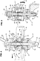
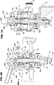
- the figure 3 is an isometric view of a setting means (12) according to an exemplary embodiment in its locked position.
- the Figures 4 to 9 are sectional representations of the adjusting means (12) in different positions of the adjusting means (12).
- the deflector device (4) is mounted on a shaft (13) directed substantially vertically (in the working position of the machine (1), its orientation corresponds to the vertical axis (Z) .
- the deflector device (4) is mounted at the lower end of the shaft (13) by means of a support (14)
- the support (14) is fixed on the shaft (13) via a nut (15).
- said at least one baffle device (4) is mounted on a vertical shaft (13) defining the vertical axis (Z) of rotation and in that that the adjusting means (12, 12A) comprises: i) a first carriage (17) guided in translation in arms (16) rigidly connected to the support structure (2) and defining the longitudinal translation axis (X), ii) a second carriage (18) housing the shaft (13) mounted in the longitudinal carriage (17) and adapted to move transversely thereto, along the transverse axis (Y), iii) a clutch (22); ) for positioning, with removable locking, the first and second carriages (17 and 18) respectively along the longitudinal axis (X) and the transverse axis (Y), and iiii) a support (14) carrying the deflector device ( 4), secured to the lower end of the vertical shaft (13) and selectively and releasing in rotation relative to the transverse carriage (18), these elements (14, 17, 18, 22) forming independent elementary
- each of these elementary adjustment means can be directly manipulated by the user without tools.
- each adjustment means (12) comprises two arms or rails (16), in the form of elongated plates spaced apart in the appended figures, fixed on the support structure (2) at one end and between which are caused to move a longitudinal carriage (17) and a carriage transverse (18).
- the shaft (13) is intended to be mounted on the transverse carriage (18).
- the longitudinal carriage (17) guides the translation along the longitudinal axis (X) and the transverse carriage (18) to guide the translation along the transverse axis (Y).
- Each arm (16) is provided with a substantially horizontal right groove (19).
- these fingers (17 ") connect rigidly with each other the opposite lateral arms (17') of the carriage (17) and slide each simultaneously in the two grooves (19).
- the longitudinal carriage (17) is equipped with a handle (20).
- the transverse carriage (18) is mounted on the longitudinal carriage (17) and is able to move transversely with respect to the longitudinal carriage (17).
- the transverse carriage (18) is equipped with a manipulation button (21), for example in the form of a rod rigidly connected to the carriage (18), extending through one of the arms (16) and provided with a knob.
- the adjusting means (12) comprises a clutch (22) which makes it possible to adjust and lock on the one hand the position of the longitudinal trolley (17) with respect to the arms (16) and the position of the transverse trolley (18) relative to to the longitudinal carriage (17).
- the dog (22) has for this purpose, two pins (23) for positioning in one of the notches (24) respectively formed on the arms (16).
- the upper part of each arm (16) is provided with at least two notches (24).
- the clutch (22) has at least two adjustment notches (25) for receiving the two pins (26) of the transverse carriage (18).
- the adjusting means (12) can be placed in two positions, a locked or clamping position ( Figures 4 and 5 ) and a position free ( Figures 6 to 9 ) to perform one or more adjustments.
- the adjusting means (12) has a cam (27) which is fixed on the vertical shaft (13) by means of an axle mounted transversely in this shaft (13) and forming its axis of rotation (28). ).
- the cam (27) is actuated by a lever (29) to move from a locked position of the adjusting means (12) to an unlocked position.
- the outer profile (30) of the cam (27) is formed accordingly.
- the outer profile (30) has a profile or segment of right profile and a profile or segment of rounded profile.
- the rounded profile has a radius (circle centered on the axis of rotation (28)) less than the distance between the axis of rotation (28) and the right profile.
- the adjusting means (12) is in its locked position ( Figures 4 and 5 ).
- the right profile is for example a flat.
- the outer profile (30) slides or rolls on the support washer (31) to generate movements for the settings of the deflector device (4).
- the adjusting means (12) is in its unlocked position (in translation or in rotation depending on the rounded profile segment concerned and the direction of tilting of the lever (29)).
- the rounded profile of the cam (27) is designed so that the clamping stroke is sufficient to release the translations along the longitudinal axis (X) and along the transverse axis (Y) and the rotation along the vertical axis ( Z).
- the angular adjustment around (Z) of the support (14) is advantageously carried out with respect to the transverse carriage (18) by a spline or tooth-to-groove connection.
- the rotational position of the support (14) carrying the deflector device (4) is given by mounting on the shaft (13) via a key.
- the lever (29) allows rapid intervention to adjust the position of the deflector device (4) relative to the working device (3). Such a cam lever allows rapid clamping. The use of an additional tool is not necessary since the manipulation is direct on the lever (29).
- the cam (27) is a double cam with two identical cam bodies, arranged spaced apart and receiving between them the lever (29) to which they are rigidly connected.
- the adjusting means (12) also comprises a spring (32).
- the spring (32) is disposed between the dog (22) and the transverse carriage (18). This spring (32) therefore urges the dog clutch (22) upwards, that is to say towards a position of disengagement of the pins (23) and (26) and thus of unlocking the carriages (17 and 18), allowing adjustment in the longitudinal and transverse directions (X and Y ) of the deflector device (4) concerned.
- the locking in translation, by engagement of the dog (22) under the action of the cam (27) moved by the lever (29) is therefore against this elastic bias.
- the position of the deflector device (4) can be easily adjusted.
- the clutch (22) is mounted so that it can be placed in two positions or states, and it is the position or state of the clutch (22) that allows or prevents the translation adjustment.
- the adjustment means (12) independently releases the translations along the axes (X, Y) and the rotation around the vertical axis (Z).
- the translation settings and the angular adjustment are independent.
- it is the position of the lever (29) relative to the soil working module (1) which releases or blocks the position of the deflector device (4).
- the central position of the lever (29) corresponding to the locked position illustrated on the Figures 4 and 5 (right profile of the cam (27) resting on the washer (31)).
- the lever (29) is rotated forward, as shown on the Figures 6 and 7 (first segment of profile rounded in support), the settings in translation are allowed.
- Angular adjustment is possible when the lever (29) is pivoted backwards, as shown in the Figures 8 and 9 (second segment of profile rounded in support).
- Such a distinction with a selective release of locks in position, limits the risk of inadvertent adjustment (in translation or rotation) and allows to intervene only on the setting (in translation or rotation) to be performed.
- the user intervenes more frequently to adjust the angle along the vertical axis (Z) in order to create a mound more or less high and wide. The intervention is fast and targeted, and does not interfere with the settings in translation.
- the shaft (13) is advantageously housed in a sleeve (33) and the cam (27) is a double cam.
- the upper end of the shaft (13) is secured to the sleeve (33) by means of a guide pin (34).
- the cam (27) is secured to the upper part of the sleeve (33) by means of the axis of rotation (28).
- the bearing washer (31), the dog (22) and the transverse carriage (18) are mounted on the sleeve (33) and are held by a nut.
- the cam (27) has an inner profile (35).
- the guide pin (34) is intended to move in this inner profile (35) as a groove.
- the Figures 6 and 7 illustrate the adjustment means (12) in an unlocked position which allows the translation adjustments along the longitudinal axis (X) and the transverse axis (Y).
- the lever (29) has been pivoted forward to release the clutch (22). Adjustment along the vertical axis (Z) is not possible.
- the clutch (22) is released under the effect of the spring (32) since the outer profile (30) of the cam (27) reduces the distance between the axis of rotation (28) and the clutch (22), whose minimum value is imposed by the cam (27).
- the pins (23) and the pins (26) are released from their respective housing (authorized lifting of the clutch (22) under the action of the spring (32).
- the Figures 8 and 9 illustrate the setting means (12) in another unlocked position permitting adjustment in rotation about the vertical axis (Z).
- the lever (29) has been pivoted backwards to disengage the transverse carriage (18) and the support (14) from the deflector device (4). Adjustment in translation along the longitudinal and transverse axes (X and Y) is not allowed.
- the outer profile of the cam (27) is such that the distance between the outer profile and the axis of rotation (28) is substantially the same in the locked positions (lever (29) directed upwards - Figures 4 and 5 ) and pivoted to the rear of the lever (29). In this last position, only the rotation setting is therefore allowed.
- the inner profile (35) of the cam (27), in which the guide axis (34) circulates is such that the distance between the axis of rotation (28) and the guide axis (34) ) is increased when the lever (29), and thus the cam (27), is moved from its locked (vertical) position to its rearward facing position ( Fig. 8 and 9 ).
- the upper splines (14 ') of the support (14) can then be positioned differently by relative rotation between the support (14) and the carriage (18), relative to the lower grooves (18') of the transverse carriage (18).
- the assembly also includes a spring lower (36) whose function is to support the weight of the deflector device (4) hooked to the shaft (13).
- the latter to which the deflector device (4) is fixed, is supported on the lower spring (36) via a washer (40) mounted on the lower end of a tubular jacket (40 '), surrounding the sleeve assembly (33) / shaft (13) and connected to these components by the guide shaft (34).
- the transverse carriage (18) and the support (14) have respective engagement means (18 ', 14') adapted and adapted to mutually cooperate for (14 and 18) to rotate about the vertical axis (Z), the locking and unlocking of said engagement means (18 ', 14') resulting from a different relative positioning (along the vertical axis (Z)) between the shaft (13) and the sleeve (33) ) determined by the position of the locking / unlocking member (27, 29; 27A, 29A).
- the unlocking of the adjusting means (12) for a modification of the angular position of the deflector device (4) around the vertical axis (Z) is therefore obtained by making a relative vertical displacement between the shaft (13) and the sheath (33), resulting in mutual disengagement of the splines (14 ') and (18').
- the support (14), and therefore the deflector device (4) to which it is connected, can then freely rotate around the shaft (13) and the axis (Z).
- the adjusting means (12) comprises a multiple indexing system (37) for locating the position of the deflector disk (4) respectively along the longitudinal axis (X), the transverse axis (Y) or the vertical axis (Z).
- the indexing along the longitudinal axis (X) is provided directly on the upper part of the arms (16). It is a rack with several notches (24). Each notch (24) corresponds to a setting position making it possible to advance or even back the deflector device (4) with respect to the working device (3).
- the transverse adjustment allows in particular to approach or move laterally the deflector device (4) of the working device (3).
- the indexing along the transverse axis (Y) is achieved thanks to the different notches (25) made on the dog clutch (22).
- the upper part of the arms (16) is provided with seven notches (24) and the clutch (22) has five notches (25).
- the indexing along the vertical axis (Z) makes it possible to identify the orientation of the deflector device (4) according to the working device (3).
- the indexing is done via a graduated plate on the claw (22) and a position indicator fixed on the shaft (13).
- FIGS. 3A to 9A represent a second embodiment of an adjusting means (12A) according to the present invention.
- This adjusting means (12A) comprises a number of elements which have been previously described. These elements will therefore keep the same reference number and will not be described again. It also comprises a number of elements that are comparable to elements of the adjustment means (12) described above. These elements will be assigned the same reference number as these comparable elements of the adjusting means (12) followed by the letter A. They are described below only if this is necessary for the understanding of the second embodiment of FIG. the invention.
- the adjusting means (12A) according to this second embodiment is generally similar to that previously described. The differences lie in the shape of the outer profile (30A) of the cam (27A) and in a lever (29A) having a latch (38A).
- the outer profile (30A) has only a rounded profile, the right profile has been removed from the first embodiment.
- the lever (29A) has a latch (38A) for locking the cam (27A) in at least one position.
- the Figures 3A , 4A and 5A illustrate the adjusting means (12A) in its locked position used for the work.
- the position of the cam (27A) is locked thanks to the lock (38A) locked in the upper part of the sleeve (33A).
- the latch (38A) is aligned with the axis of rotation (28) and the guide axis (34).
- the upper portion of the sleeve (33A) has a recess for receiving the latch (38A).
- the Figures 6A to 9A show the cam (27A) in these two positions allowing adjustment of the deflector device (4). Before the lever (29A) can be manipulated, it is necessary to unlock the latch (38A) by changing the state of the spring handle (39A). When the lock (38A) is not aligned with the axis of rotation (28) and the guide axis (34), the lever (29A) can be manipulated.
- the adjustment means (12, 12A) according to the invention can be used on any type of machine comprising a baffle device (4) which can be adjusted relative to a corresponding working device (3).
- Each soil working module (1) may have a single deflector device (4)
- the support structure (2) of the module (1) advantageously comprises two deflector devices (4), with a deflector device (4) extending laterally on each side of the working device (3), each of said deflector devices (4) being provided with adjusting means (12; 12A).
- each deflector device (4) may consist of a disk.
- the invention also relates to figures 1 and 2 ) a tillage machine comprising a beam on which is fixed at least one tillage unit (1) according to any one of claims 1 to 13.
Landscapes
- Life Sciences & Earth Sciences (AREA)
- Engineering & Computer Science (AREA)
- Mechanical Engineering (AREA)
- Soil Sciences (AREA)
- Environmental Sciences (AREA)
- Zoology (AREA)
- Soil Working Implements (AREA)
Abstract
Module de travail du sol avec un dispositif déflecteur muni d'un moyen de réglage perfectionné et machine agricole présentant au moins un tel module. La présente invention concerne un module de travail du sol (1) comportant une structure support (2), un dispositif de travail (3) monté sur la structure support (2) et au moins un dispositif déflecteur (4), ledit au moins un dispositif déflecteur (4) est monté sur la structure support (2) de manière déplaçable par rapport au dispositif de travail (3). Le module de travail du sol (1) est remarquable en ce qu'il est prévu un moyen de réglage (12) pour régler ledit au moins un dispositif déflecteur (4) en translation suivant un axe longitudinal (X), en translation suivant un axe transversal et en rotation autour d'un axe vertical (Z). La présente invention concerne également une machine de travail du sol comportant au moins un module de travail du sol.Soil working module with a deflector device provided with an improved adjustment means and agricultural machine having at least one such module. The present invention relates to a soil working module (1) comprising a support structure (2), a working device (3) mounted on the support structure (2) and at least one deflector device (4), said at least one deflector device (4) is mounted on the support structure (2) displaceably relative to the working device (3). The soil working module (1) is remarkable in that an adjusting means (12) is provided for adjusting said at least one deflector device (4) in translation along a longitudinal axis (X), in translation along a transverse axis and in rotation about a vertical axis (Z). The present invention also relates to a tillage machine comprising at least one tillage module.
Description
La présente invention se rapporte au domaine technique général du machinisme agricole et notamment aux machines agricoles destinées à travailler le sol. L'invention concerne, comme indiqué dans le préambule de la revendication 1, un module de travail du sol comportant une structure support, un dispositif de travail monté sur la structure support et au moins un dispositif déflecteur, ledit au moins un dispositif déflecteur est monté sur la structure support de manière déplaçable par rapport au dispositif de travail.The present invention relates to the general technical field of agricultural machinery and especially agricultural machinery for working the soil. The invention relates, as indicated in the preamble of
Un module de ce type est connu par le document
Sur d'autres modules de travail du sol, les réglages des dispositifs déflecteurs, par rapport au dispositif de travail, sont simplifiés puisqu'ils ne nécessitent pas un démontage complet du boulon. Néanmoins, chaque réglage doit être réalisé de manière séparée avec ou sans clé de serrage.On other tillage modules, the settings of the baffle devices, relative to the working device, are simplified since they do not require complete disassembly of the bolt. Nevertheless, each adjustment must be done separately with or without a spanner.
D'autres exemples de modules du même type, présentant les mêmes limitations en termes de complexité de mise en oeuvre des réglages, voire présentant des possibilités de réglage moins nombreuses, sont connus des documents
La présente invention a pour but de remédier aux inconvénients précités. Elle doit notamment proposer un module de travail du sol dont les réglages du ou des dispositif(s) déflecteur (s) associés (s) à chaque dispositif de travail sont plus faciles et rapides.The present invention aims to overcome the aforementioned drawbacks. In particular, it must propose a tillage module whose settings of the baffle device (s) associated with each working device are easier and faster.
A cet effet, en accord avec la partie caractérisante de la revendication 1, une importante caractéristique de l'invention consiste en ce qu'il est prévu un moyen de réglage pour régler ledit au moins un dispositif déflecteur en translation suivant un axe longitudinal, en translation suivant un axe transversal et en rotation autour d'un axe vertical. Ainsi, selon l'invention, un même moyen de réglage permet de réaliser un positionnement spatial complexe du dispositif déflecteur concerné par des réglages en translation selon deux axes perpendiculaires d'un plan (définissant ensemble, par exemple, un plan horizontal) et un réglage en rotation autour d'un troisième axe perpendiculaire audit plan. De plus, grâce au moyen de réglage, les manipulations se font sans outils additionnels et sans démontage. Les manipulations sont donc plus faciles et bien plus rapides pour adapter la position du dispositif déflecteur par rapport au dispositif de travail. Les manipulations sont également diminuées lorsque les réglages en translation et en rotation peuvent être effectués simultanément ou de manière sélective.For this purpose, in accordance with the characterizing part of
Préférentiellement, le moyen de réglage libère indépendamment les translations suivant un axe longitudinal et suivant un axe transversal et la rotation autour de l'axe vertical. Grâce à cet arrangement, le réglage de l'angle d'attaque demeure inchangé lorsqu'un réglage en translation est effectué.Preferably, the adjustment means independently releases the translations along a longitudinal axis and along a transverse axis and the rotation about the vertical axis. Thanks to this arrangement, the setting of the angle of attack remains unchanged when a translation adjustment is made.
Les revendications dépendantes 2 à 13 présentent d'autres caractéristiques et variantes de réalisations avantageuses de l'invention.The dependent claims 2 to 13 have other features and variants of advantageous embodiments of the invention.
D'autres caractéristiques et avantages de l'invention se dégageront de la description qui va suivre en regard des dessins annexés qui ne sont donnés qu'à titre d'exemples non limitatifs de l'invention. Sur ces dessins :
- la
figure 1 représente une vue de côté d'un module de travail du sol en position de travail conforme à l'invention, - la
figure 2 représente une vue arrière d'une machine de travail du sol comportant plusieurs modules de travail du sol selon l'invention, - les
figures 3 et 3A représentent une vue en perspective d'un moyen de réglage conforme à l'invention, selon deux variantes de réalisation partiellement différentes, - les
figures 4, 5 et 4A, 5A représentent une vue en coupe du moyen de réglage dans sa position verrouillée pour le travail, - les
figures 6, 7 et 6A, 7A représentent une vue en coupe du moyen de réglage dans sa position déverrouillée pour le réglage des translations, - les
figures 8, 9 et 8A, 9A représentent une vue en coupe du moyen de réglage dans sa position déverrouillée pour le réglage de la rotation, - la
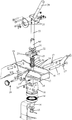
figure 10 est une vue éclatée du moyen de réglage représentéfigure 3 .
- the
figure 1 represents a side view of a soil working module in working position according to the invention, - the
figure 2 represents a rear view of a tillage machine comprising several tillage modules according to the invention, - the
Figures 3 and 3A represent a perspective view of a control means according to the invention, according to two partially different embodiments, - the
Figures 4, 5 and 4A, 5A represent a sectional view of the adjustment means in its locked position for the work, - the
Figures 6, 7 and 6A, 7A represent a sectional view of the adjustment means in its unlocked position for adjusting the translations, - the
Figures 8, 9 and 8A, 9A represent a sectional view of the adjusting means in its unlocked position for adjusting the rotation, - the
figure 10 is an exploded view of the adjustment means shownfigure 3 .
Sur la
Dans l'exemple représenté sur la
La
Grâce à la fixation par bridage des modules de travail du sol (1) sur la poutre transversale (6), l'écartement entre les bandes pourra être adapté en fonction des besoins de l'utilisateur. Généralement, l'écartement entre deux modules de travail du sol (1) voisin est adapté en fonction de la culture à implanter. Selon la largeur de la machine de travail du sol (5), la poutre transversale (6) est configurée en une ou plusieurs sections. Le nombre de modules de travail du sol (1) varient en fonction de la largeur de travail de la machine de travail du sol (5) et de l'écartement souhaité entre les bandes.Thanks to the fixing by clamping of the soil working modules (1) on the transverse beam (6), the spacing between the strips can be adapted according to the needs of the user. Generally, the spacing between two adjacent soil working modules (1) is adapted according to the culture to be implanted. Depending on the width of the soil working machine (5), the cross beam (6) is configured in one or more sections. The number of tillage modules (1) vary depending on the working width of the tillage machine (5) and the desired gap between tapes.
D'après la
La
Selon une caractéristique importante de l'invention, le module de travail du sol (1) comporte un moyen de réglage (12) pour régler ledit au moins un dispositif déflecteur (4) à la fois en translation suivant un axe longitudinal (X), en translation suivant un axe transversal (Y) et en rotation autour d'un axe vertical (Z). Grâce à ce moyen de réglage (12) unique et polyvalent, les manipulations se font sans outils additionnels et sans démontage de broche, goupille ou écrou, ledit moyen de réglage (12) faisant partie intégrante du module (1) considéré et pouvant être directement manipulé par l'utilisateur. Les manipulations sont donc plus faciles et bien plus rapides pour adapter la position du dispositif déflecteur (4) par rapport au dispositif de travail (3). Les manipulations sont également diminuées lorsque, selon une construction possible de l'invention, les réglages en translation et en rotation peuvent être effectués simultanément.According to an important characteristic of the invention, the soil working module (1) comprises an adjustment means (12) for adjusting said at least one baffle device (4) both in translation along a longitudinal axis (X), in translation along a transverse axis (Y) and in rotation around a vertical axis (Z). Thanks to this unique and versatile adjustment means (12), the manipulations are carried out without additional tools and without disassembly of the spindle, pin or nut, said adjustment means (12) forming an integral part of the module (1) under consideration and which can be directly manipulated by the user. Manipulations are therefore easier and much faster to adapt the position of the deflector device (4) relative to the working device (3). The manipulations are also reduced when, according to a possible construction of the invention, the translation and rotation settings can be performed simultaneously.
L'adaptation du dispositif déflecteur (4) par rapport au dispositif de travail (3) est donc bien plus facile et rapide. Le moyen de réglage (12) réalise selon l'invention notamment une fonction de serrage (12) permettant d'assurer, de manière amovible ou libérable, un blocage ou un maintien d'une position déterminée du dispositif déflecteur (4) dans l'espace. Ce serrage est apte à résister aux efforts transmis au cours du travail, sans risque de déréglage, c'est-à-dire sans risque de modification de la position du dispositif déflecteur (4), le moyen de réglage (12) étant dans un état de serrage actif ou de blocage en position. La direction des axes (X, Y et Z) est indiquée comme respectivement longitudinale, transversale et verticale. La présente invention porte aussi sur un réglage dont l'un des axes (X, Y, Z) est dirigé sensiblement longitudinalement, sensiblement transversalement ou sensiblement verticalement.The adaptation of the deflector device (4) relative to the working device (3) is therefore much easier and faster. The adjusting means (12), according to the invention, in particular performs a clamping function (12) which makes it possible, in a removable or releasable manner, to block or hold a predetermined position of the deflector device (4) in the space. This clamping is able to withstand the forces transmitted during work, without risk of maladjustment, that is to say without risk of modifying the position of the deflector device (4), the adjustment means (12) being in a position clamping state active or locking in position. The direction of the axes (X, Y and Z) is indicated as respectively longitudinal, transverse and vertical. The present invention also relates to a setting of which one of the axes (X, Y, Z) is directed substantially longitudinally, substantially transversely or substantially vertically.
Selon une autre caractéristique de l'invention, le moyen de réglage (12) sous forme de moyen de serrage permet de verrouiller, respectivement de déverrouiller, les translations suivant les axes (X et Y) et/ou la rotation suivant l'axe vertical (Z) du dispositif déflecteur (4). Grâce à cette caractéristique, lorsque le moyen de réglage (12) est déverrouillé, le dispositif déflecteur (4) peut être réglé dans l'espace. Les réglages en translation et en rotation sont réalisés sans outils supplémentaires. Le dispositif déflecteur (4) pourra ainsi être réglé très facilement pour être adapté aux conditions du terrain. Ainsi, le moyen de réglage (12) constitue un moyen de réglage avec blocage et verrouillage amovibles en position du dispositif déflecteur (4).According to another characteristic of the invention, the adjustment means (12) in the form of clamping means makes it possible to lock, respectively to unlock, the translations along the axes (X and Y) and / or the rotation along the vertical axis (Z) of the deflector device (4). With this feature, when the setting means (12) is unlocked, the deflector device (4) can be set in space. The translation and rotation settings are made without additional tools. The deflector device (4) can thus be adjusted very easily to be adapted to the conditions of the ground. Thus, the adjustment means (12) constitutes adjusting means with locking and locking removable in position of the deflector device (4).
Préférentiellement, le moyen de réglage (12, 12A) comprend un organe (27, 29 ; 27A, 29A) unique permettant de verrouiller respectivement de déverrouiller les translations suivant les axes longitudinal (X) et transversal (Y) ou la rotation suivant l'axe vertical (Z) dudit au moins un dispositif déflecteur (4) et cet organe de verrouillage/déverrouillage (27, 29 ; 27A, 29A) du moyen de réglage (12, 12A) est avantageusement apte et destiné à libérer indépendamment les translations (X, Y) et la rotation autour de l'axe vertical (Z).Preferably, the adjusting means (12, 12A) comprises a single member (27, 29; 27A, 29A) for locking respectively unlocking the translations along the longitudinal (X) and transverse (Y) axes or the rotation according to the vertical axis (Z) of said at least one deflector device (4) and this locking / unlocking member (27, 29; 27A, 29A) of the adjusting means (12, 12A) is advantageously adapted and intended to release the translations independently ( X, Y) and rotation around the vertical axis (Z).
De manière avantageuse, l'organe de verrouillage/déverrouillage (27, 29 ; 27A, 29A) est pivotant, et apte et destiné à déterminer trois états pour ledit moyen de réglage (12, 12A), à savoir un état verrouillé et deux états de déverrouillage sélectif. Cet organe (27, 29 ; 27A, 29A) est conçu de telle manière qu'il puisse, à partir d'une position centrale ou médiane de verrouillage du moyen de réglage (12, 12A), pivoter dans un sens pour autoriser les mouvements de translation et pivoter dans l'autre sens pour autoriser le mouvement de rotation.Comme le montrent les figures annexées, il est avantageusement prévu que le moyen de réglage (12 ; 12A) comprenne plusieurs moyens de réglage élémentaires (14, 17, 18, 22) aptes et destinés chacun à permettre de réaliser au moins un réglage en translation selon l'un des axes longitudinal (X) et transversal (Y) ou en rotation autour de l'axe vertical (Z), et en ce que ledit moyen de réglage (12, 12A) comprend un unique organe (27, 29 ; 27A, 29A) assurant, de manière libérable, un verrouillage dans une position de réglage déterminée, en translation et en rotation, du dispositif déflecteur (4) concerné.Advantageously, the locking / unlocking member (27, 29; 27A, 29A) is pivotable, and adapted and intended to determine three states for said adjusting means (12, 12A), namely a locked state and two states. selective unlocking. This member (27, 29; 27A, 29A) is designed such that it can, from a central or central locking position of the adjusting means (12, 12A), pivot in one direction to allow the movements translationally and rotate in the other direction to allow the rotational movement.As shown in the accompanying figures, it is advantageously provided that the adjusting means (12; 12A) comprises a plurality of elementary adjustment means (14, 17, 18, 22) each adapted to allow at least one adjustment in translation along one of the longitudinal (X) and transverse (Y) axes or in rotation about the vertical axis (Z), and in that said means adjusting member (12, 12A) comprises a single member (27, 29; 27A, 29A) releasably securing a locking in a determined, translational and rotational setting position of the deflector device (4) concerned.
Afin d'aboutir à une solution compacte, autorisant un réglage complet en un endroit donné, les différents moyens de réglage élémentaires (14, 17, 18, 22) sont intégrés dans une même unité structurelle et fonctionnelle laquelle assure un montage réglable du dispositif déflecteur (4) concerné sur la structure support (2), l'organe de verrouillage unique (29, 29A ; 27, 27A) associé à ladite unité (et faisant partie de cette dernière) étant apte et destiné à réaliser, d'une part, un verrouillage avec blocage en position du dispositif déflecteur (4) et, d'autre part, un déverrouillage sélectif d'au moins un desdits moyens de réglage élémentaires (14, 17, 18, 22), par simple déplacement dudit organe par l'utilisateur.In order to achieve a compact solution, allowing a complete adjustment in a given place, the various elementary adjustment means (14, 17, 18, 22) are integrated in the same structural and functional unit which ensures an adjustable mounting of the deflector device. (4) concerned on the support structure (2), the single locking member (29, 29A; 27, 27A) associated with said unit (and forming part of the latter) being adapted and intended to perform, on the one , a lock with position locking of the deflector device (4) and, on the other hand, a selective unlocking of at least one of said elementary adjustment means (14, 17, 18, 22) by simply moving said member by the user.
La
En accord avec un mode de réalisation constructive pratique de l'invention, représenté aux dessins annexés, ledit au moins un dispositif déflecteur (4) est monté sur un arbre vertical (13) définissant l'axe vertical (Z) de rotation et en ce que le moyen de réglage (12, 12A) comporte : i) un premier chariot (17) guidé en translation dans des bras (16) reliés rigidement à la structure support (2) et définissant l'axe de translation longitudinal (X), ii) un second chariot (18) logeant l'arbre (13) monté dans le chariot longitudinal (17) et apte à se déplacer transversalement par rapport à ce dernier, selon l'axe transversal (Y), iii) un crabot (22) permettant de positionner, avec verrouillage amovible, les premier et second chariots (17 et 18) respectivement selon l'axe longitudinal (X) et l'axe transversal (Y), et iiii) un support (14) portant le dispositif déflecteur (4), solidaire de l'extrémité inférieure de l'arbre vertical (13) et pouvant être sélectivement assujetti et libéré en rotation par rapport au chariot transversal (18), ces éléments (14, 17, 18, 22) formant des moyens de réglage élémentaires indépendants pouvant être sélectivement verrouillés et déverrouillés par un unique organe (27, 29 ; 27A, 29A) faisant également partie dudit moyen de réglage (12 ; 12A).In accordance with a practical constructive embodiment of the invention, shown in the accompanying drawings, said at least one baffle device (4) is mounted on a vertical shaft (13) defining the vertical axis (Z) of rotation and in that that the adjusting means (12, 12A) comprises: i) a first carriage (17) guided in translation in arms (16) rigidly connected to the support structure (2) and defining the longitudinal translation axis (X), ii) a second carriage (18) housing the shaft (13) mounted in the longitudinal carriage (17) and adapted to move transversely thereto, along the transverse axis (Y), iii) a clutch (22); ) for positioning, with removable locking, the first and second carriages (17 and 18) respectively along the longitudinal axis (X) and the transverse axis (Y), and iiii) a support (14) carrying the deflector device ( 4), secured to the lower end of the vertical shaft (13) and selectively and releasing in rotation relative to the transverse carriage (18), these elements (14, 17, 18, 22) forming independent elementary adjusting means being selectively latchable and unlocked by a single member (27, 29; 27A, 29A) also forming part of said adjusting means (12; 12A).
On peut remarquer que chacun de ces moyens de réglage élémentaires peut être directement manipulé par l'utilisateur sans outil.It may be noted that each of these elementary adjustment means can be directly manipulated by the user without tools.
Ainsi, afin de réaliser les différents réglages, chaque moyen de réglage (12) comporte deux bras ou rails (16), sous forme de plaques allongées espacées sur les figures annexées, fixés sur la structure support (2) par une extrémité et entre lesquels sont amenés à se déplacer un chariot longitudinal (17) et un chariot transversal (18). L'arbre (13) est destiné à être monté sur le chariot transversal (18). Le chariot longitudinal (17) permet de guider la translation selon l'axe longitudinal (X) et le chariot transversal (18) permet de guider la translation selon l'axe transversal (Y). Chaque bras (16) est muni d'une rainure droite (19) sensiblement horizontale. Le chariot longitudinal (17), placé entre les deux bras (16), se déplace dans ces rainures (19) pour le réglage selon l'axe longitudinal (X), en étant guidé en translation par des doigts transversaux (17") circulant dans ces rainures (19) et solidaires des bras latéraux (17') du chariot (17). Dans le cadre de la construction préférentielle représentée, ces doigts (17") relient rigidement entre eux les bras latéraux opposés (17') du chariot (17) et coulissent chacun simultanément dans les deux rainures (19). Pour faciliter ce réglage en translation, le chariot longitudinal (17) est équipé d'une poignée (20). Le chariot transversal (18) est monté sur le chariot longitudinal (17) et est susceptible de se déplacer transversalement par rapport au chariot longitudinal (17). Pour faciliter le réglage en translation selon l'axe transversal (Y), le chariot transversal (18) est équipé d'un bouton de manipulation (21), par exemple sous la forme d'une tige reliée rigidement au chariot (18), s'étendant à travers l'un des bras (16) et pourvue d'un pommeau. Le moyen de réglage (12) comporte un crabot (22) qui permet de régler et de verrouiller d'une part la position du chariot longitudinal (17) par rapport aux bras (16) et la position du chariot transversal (18) par rapport au chariot longitudinal (17). Le crabot (22) possède à cet effet, deux pions (23) destinés à se positionner dans l'un des crans (24) respectifs ménagés sur les bras (16). La partie supérieure de chaque bras (16) est muni d'au moins deux crans (24). Le crabot (22) possède au moins deux encoches (25) de réglage destinées à recevoir les deux pions (26) du chariot transversal (18).Thus, in order to carry out the various adjustments, each adjustment means (12) comprises two arms or rails (16), in the form of elongated plates spaced apart in the appended figures, fixed on the support structure (2) at one end and between which are caused to move a longitudinal carriage (17) and a carriage transverse (18). The shaft (13) is intended to be mounted on the transverse carriage (18). The longitudinal carriage (17) guides the translation along the longitudinal axis (X) and the transverse carriage (18) to guide the translation along the transverse axis (Y). Each arm (16) is provided with a substantially horizontal right groove (19). The longitudinal carriage (17), placed between the two arms (16), moves in these grooves (19) for adjustment along the longitudinal axis (X), being guided in translation by transverse fingers (17 ") flowing in these grooves (19) and integral with the lateral arms (17 ') of the carriage (17). In the context of the preferred construction shown, these fingers (17 ") connect rigidly with each other the opposite lateral arms (17') of the carriage (17) and slide each simultaneously in the two grooves (19). To facilitate this adjustment in translation, the longitudinal carriage (17) is equipped with a handle (20). The transverse carriage (18) is mounted on the longitudinal carriage (17) and is able to move transversely with respect to the longitudinal carriage (17). To facilitate the adjustment in translation along the transverse axis (Y), the transverse carriage (18) is equipped with a manipulation button (21), for example in the form of a rod rigidly connected to the carriage (18), extending through one of the arms (16) and provided with a knob. The adjusting means (12) comprises a clutch (22) which makes it possible to adjust and lock on the one hand the position of the longitudinal trolley (17) with respect to the arms (16) and the position of the transverse trolley (18) relative to to the longitudinal carriage (17). The dog (22) has for this purpose, two pins (23) for positioning in one of the notches (24) respectively formed on the arms (16). The upper part of each arm (16) is provided with at least two notches (24). The clutch (22) has at least two adjustment notches (25) for receiving the two pins (26) of the transverse carriage (18).
Comme le montrent les
D'une manière avantageuse, le moyen de réglage (12) peut être placé dans deux positions, une position verrouillée ou de serrage (
Selon une caractéristique importante de l'invention, le moyen de réglage (12) libère indépendamment les translations selon les axes (X, Y) et la rotation autour de l'axe vertical (Z). Ainsi, les réglages en translation et le réglage angulaire sont indépendants. En pratique, c'est la position du levier (29) par rapport au module de travail du sol (1) qui libère ou bloque la position du dispositif déflecteur (4). La position centrale du levier (29) correspondant à la position verrouillée illustrée sur les
Comme le montrent les vues en coupe, l'arbre (13) est avantageusement logé dans un fourreau (33) et la came (27) est une double came. L'extrémité supérieure de l'arbre (13) est solidarisée sur le fourreau (33) au moyen d'un axe de guidage (34). La came (27) est solidarisée sur la partie supérieure du fourreau (33) au moyen de l'axe de rotation (28). La rondelle d'appui (31), le crabot (22) et le chariot transversal (18) sont montés sur le fourreau (33) et sont maintenus par un écrou. En plus du profil extérieur (30), la came (27) dispose d'un profil intérieur (35). L'axe de guidage (34) est destiné à se déplacer dans ce profil intérieur (35) sous forme de rainure.As shown in sectional views, the shaft (13) is advantageously housed in a sleeve (33) and the cam (27) is a double cam. The upper end of the shaft (13) is secured to the sleeve (33) by means of a guide pin (34). The cam (27) is secured to the upper part of the sleeve (33) by means of the axis of rotation (28). The bearing washer (31), the dog (22) and the transverse carriage (18) are mounted on the sleeve (33) and are held by a nut. In addition to the outer profile (30), the cam (27) has an inner profile (35). The guide pin (34) is intended to move in this inner profile (35) as a groove.
Les
Les
Ce dernier, auquel le dispositif déflecteur (4) est fixé, prend appui sur le ressort inférieur (36) par l'intermédiaire d'une rondelle (40) montée sur l'extrémité inférieure d'une chemise tubulaire (40'), entourant l'ensemble fourreau (33)/arbre (13) et reliée à ces composants par l'axe de guidage (34).The latter, to which the deflector device (4) is fixed, is supported on the lower spring (36) via a washer (40) mounted on the lower end of a tubular jacket (40 '), surrounding the sleeve assembly (33) / shaft (13) and connected to these components by the guide shaft (34).
Ainsi, le chariot transversal (18) et le support (14) présente des moyens d'engagement respectifs (18', 14') aptes et destinés à coopérer mutuellement pour les (14 et 18) assujettir en rotation autour de l'axe vertical (Z), le verrouillage et le déverrouillage desdits moyens d'engagement (18', 14') résultant d'un positionnement relatif différent (selon l'axe vertical (Z)) entre l'arbre (13) et le fourreau (33) déterminé par la position de l'organe de verrouillage/déverrouillage (27, 29 ; 27A, 29A).Thus, the transverse carriage (18) and the support (14) have respective engagement means (18 ', 14') adapted and adapted to mutually cooperate for (14 and 18) to rotate about the vertical axis (Z), the locking and unlocking of said engagement means (18 ', 14') resulting from a different relative positioning (along the vertical axis (Z)) between the shaft (13) and the sleeve (33) ) determined by the position of the locking / unlocking member (27, 29; 27A, 29A).
Le déverrouillage du moyen de réglage (12) pour une modification de la position angulaire du dispositif déflecteur (4) autour de l'axe vertical (Z) est par conséquent obtenu en réalisant un déplacement vertical relatif entre l'arbre (13) et le fourreau (33), aboutissant à un désengagement mutuel des cannelures (14') et (18'). Le support (14), et donc le dispositif déflecteur (4) auquel il est relié, peut alors librement tourner autour de l'arbre (13) et de l'axe (Z).The unlocking of the adjusting means (12) for a modification of the angular position of the deflector device (4) around the vertical axis (Z) is therefore obtained by making a relative vertical displacement between the shaft (13) and the sheath (33), resulting in mutual disengagement of the splines (14 ') and (18'). The support (14), and therefore the deflector device (4) to which it is connected, can then freely rotate around the shaft (13) and the axis (Z).
Pour faciliter les réglages et permettre une répétabilité, le moyen de réglage (12) comporte un système d'indexation (37) multiple pour repérer la position du disque déflecteur (4) respectivement suivant l'axe longitudinal (X), l'axe transversal (Y) ou l'axe vertical (Z). L'indexage selon l'axe longitudinal (X) est prévu directement sur la partie supérieure des bras (16). Il s'agit d'une crémaillère disposant de plusieurs crans (24). Chaque cran (24) correspond à une position de réglage permettant d'avancer voire de reculer le dispositif déflecteur (4) par rapport au dispositif de travail (3). Le réglage transversal permet notamment d'approcher ou d'éloigner latéralement le dispositif déflecteur (4) du dispositif de travail (3). L'indexage selon l'axe transversal (Y) est réalisé grâce aux différentes encoches (25) réalisées sur le crabot (22). Dans l'exemple de réalisation des figures, la partie supérieure des bras (16) est muni de sept crans (24) et le crabot (22) possède cinq encoches (25). L'indexage selon l'axe vertical (Z) permet de repérer l'orientation du dispositif déflecteur (4) en fonction du dispositif de travail (3). L'indexage se fait via une platine graduée sur le crabot (22) et un indicateur de position fixé sur l'arbre (13).To facilitate adjustments and to allow repeatability, the adjusting means (12) comprises a multiple indexing system (37) for locating the position of the deflector disk (4) respectively along the longitudinal axis (X), the transverse axis (Y) or the vertical axis (Z). The indexing along the longitudinal axis (X) is provided directly on the upper part of the arms (16). It is a rack with several notches (24). Each notch (24) corresponds to a setting position making it possible to advance or even back the deflector device (4) with respect to the working device (3). The transverse adjustment allows in particular to approach or move laterally the deflector device (4) of the working device (3). The indexing along the transverse axis (Y) is achieved thanks to the different notches (25) made on the dog clutch (22). In the embodiment of the figures, the upper part of the arms (16) is provided with seven notches (24) and the clutch (22) has five notches (25). The indexing along the vertical axis (Z) makes it possible to identify the orientation of the deflector device (4) according to the working device (3). The indexing is done via a graduated plate on the claw (22) and a position indicator fixed on the shaft (13).
Les
Le moyen de réglage (12, 12A) selon l'invention peut être utilisé sur tout type de machines comportant un dispositif déflecteur (4) qui peut être réglé par rapport à un dispositif de travail (3) correspondant.The adjustment means (12, 12A) according to the invention can be used on any type of machine comprising a baffle device (4) which can be adjusted relative to a corresponding working device (3).
Chaque module de travail du sol (1) peut présenter un unique dispositif déflecteur (4)Each soil working module (1) may have a single deflector device (4)
Toutefois, en variante, et comme représenté aux
De plus, chaque dispositif déflecteur (4) peut consister en un disque.In addition, each deflector device (4) may consist of a disk.
L'invention concerne également (
Il est bien évident que l'invention n'est pas limitée aux modes de réalisation décrits ci-dessus et représentés sur les dessins annexés. Des modifications restent possibles, notamment en ce qui concerne la constitution ou le nombre des divers éléments ou par substitution d'équivalents techniques, sans pour autant sortir du domaine de protection tel qu'il est défini par les revendications suivantes.It is obvious that the invention is not limited to the embodiments described above and shown in the accompanying drawings. Modifications remain possible, in particular as regards the constitution or the number of the various elements or by substitution of technical equivalents, without departing from the scope of protection as defined by the following claims.
Claims (14)
Applications Claiming Priority (1)
| Application Number | Priority Date | Filing Date | Title |
|---|---|---|---|
| FR1458953A FR3025970B1 (en) | 2014-09-23 | 2014-09-23 | SOIL WORKING MODULE WITH A DEFLECTOR DISK HAVING AN IMPROVED ADJUSTMENT MEANS AND AGRICULTURAL MACHINE HAVING AT LEAST ONE MODULE ACCORDING TO THE INVENTION |
Publications (2)
| Publication Number | Publication Date |
|---|---|
| EP3000296A1 true EP3000296A1 (en) | 2016-03-30 |
| EP3000296B1 EP3000296B1 (en) | 2017-08-30 |
Family
ID=51866215
Family Applications (1)
| Application Number | Title | Priority Date | Filing Date |
|---|---|---|---|
| EP15306474.6A Active EP3000296B1 (en) | 2014-09-23 | 2015-09-22 | Soil-working module with a deflector device provided with improved adjustment means and agricultural machine having at least one such module |
Country Status (2)
| Country | Link |
|---|---|
| EP (1) | EP3000296B1 (en) |
| FR (1) | FR3025970B1 (en) |
Citations (6)
| Publication number | Priority date | Publication date | Assignee | Title |
|---|---|---|---|---|
| US3327786A (en) | 1966-03-09 | 1967-06-27 | Deere & Co | Herbicide incorporator |
| US4738316A (en) | 1986-08-11 | 1988-04-19 | Deere & Company | Adjustable shank mounting for an earthworking tool |
| US4928774A (en) | 1987-08-04 | 1990-05-29 | Landoll Corporation | Cultivator with improved disc positioning means |
| US5333694A (en) | 1992-05-01 | 1994-08-02 | Roggenbuck David C | Strip-till seed bed preparation apparatus |
| US5361848A (en) | 1992-09-09 | 1994-11-08 | Fleischer Manufacturing, Inc. | Agricultural cultivator |
| US5623997A (en) | 1995-08-29 | 1997-04-29 | Unverferth Manufacturing Co., Inc. | Soil zone-builder coulter closer/tiller |
-
2014
- 2014-09-23 FR FR1458953A patent/FR3025970B1/en active Active
-
2015
- 2015-09-22 EP EP15306474.6A patent/EP3000296B1/en active Active
Patent Citations (6)
| Publication number | Priority date | Publication date | Assignee | Title |
|---|---|---|---|---|
| US3327786A (en) | 1966-03-09 | 1967-06-27 | Deere & Co | Herbicide incorporator |
| US4738316A (en) | 1986-08-11 | 1988-04-19 | Deere & Company | Adjustable shank mounting for an earthworking tool |
| US4928774A (en) | 1987-08-04 | 1990-05-29 | Landoll Corporation | Cultivator with improved disc positioning means |
| US5333694A (en) | 1992-05-01 | 1994-08-02 | Roggenbuck David C | Strip-till seed bed preparation apparatus |
| US5361848A (en) | 1992-09-09 | 1994-11-08 | Fleischer Manufacturing, Inc. | Agricultural cultivator |
| US5623997A (en) | 1995-08-29 | 1997-04-29 | Unverferth Manufacturing Co., Inc. | Soil zone-builder coulter closer/tiller |
Also Published As
| Publication number | Publication date |
|---|---|
| FR3025970A1 (en) | 2016-03-25 |
| EP3000296B1 (en) | 2017-08-30 |
| FR3025970B1 (en) | 2017-03-17 |
Similar Documents
| Publication | Publication Date | Title |
|---|---|---|
| EP1705980B1 (en) | Disc tiller soil working machine | |
| EP2457426B1 (en) | Seeder with shifted support elements | |
| FR2632810A2 (en) | FOURING MACHINE WITH AT LEAST ONE ROLLING WHEEL EQUIPPED WITH ARMS TOOL HOLDERS ORDERED | |
| FR2896375A1 (en) | Soil-working machine, e.g. stubble plough, has at least two rows of discs of different diameters | |
| EP0529684B1 (en) | Agricultural soil working machine with improved stabilization element | |
| EP3000296B1 (en) | Soil-working module with a deflector device provided with improved adjustment means and agricultural machine having at least one such module | |
| FR2901453A1 (en) | Semi-mounted agricultural seeder for use with tractor, has arms and connection devices respectively connecting opener tools and implantation units on beams, and framework connected to chassis by pivot joint that is locked by locking units | |
| EP2630854B1 (en) | Soil working machine with a leveling board | |
| EP1212932B1 (en) | Seeder | |
| EP1336330B1 (en) | Sowing machine | |
| EP2923542B1 (en) | Seed drill with a console having two working tools | |
| FR2988261A1 (en) | Ground working device for working on ground prior to sowing operation, has continuous adjustment unit for adjusting spacing between modules, where each module includes tool chosen from disc opener, wheel rammer and debris flush unit | |
| FR2823174A1 (en) | Straddle tractor for vine work comprises chassis supporting rear wheel and straddle unit and has lateral beam carrying offset arm at front end supporting steering wheel offset toward working plane | |
| EP1787503A1 (en) | Sowing combination | |
| FR3064879B1 (en) | DRIVE SYSTEM FOR AN AGRICULTURAL MACHINE COMPRISING A DRIVE WHEEL IN CONTACT WITH REMOVABLE SOIL IN TRANSPORT POSITION, AND AGRICULTURAL MACHINE WITH SUCH A DRIVE SYSTEM | |
| EP3375271B1 (en) | Agricultural soil preparation machine comprising two mutually offset disc trains with adjustable position in the forward direction | |
| EP0974252B1 (en) | Seeddrill | |
| EP0966875B1 (en) | Sowing machine | |
| CH221526A (en) | Harrow. | |
| EP2880969B1 (en) | Hoeing device intended for being towed, comprising a deformable parallelogram supporting at least one hoeing element | |
| FR3012721A1 (en) | ||
| FR2534443A1 (en) | COMBINATION OF A MACHINE FOR WORKING THE SOIL WITH A SECOND MACHINE, FOR EXAMPLE A SEEDER | |
| EP4094554A1 (en) | Assembly comprising an agricultural soil-working tool and an additional agricultural tool | |
| EP3403482A1 (en) | Frame supporting soil-tilling tools with raising central rear section | |
| BE487861A (en) |
Legal Events
| Date | Code | Title | Description |
|---|---|---|---|
| PUAI | Public reference made under article 153(3) epc to a published international application that has entered the european phase |
Free format text: ORIGINAL CODE: 0009012 |
|
| AK | Designated contracting states |
Kind code of ref document: A1 Designated state(s): AL AT BE BG CH CY CZ DE DK EE ES FI FR GB GR HR HU IE IS IT LI LT LU LV MC MK MT NL NO PL PT RO RS SE SI SK SM TR |
|
| AX | Request for extension of the european patent |
Extension state: BA ME |
|
| 17P | Request for examination filed |
Effective date: 20160921 |
|
| RBV | Designated contracting states (corrected) |
Designated state(s): AL AT BE BG CH CY CZ DE DK EE ES FI FR GB GR HR HU IE IS IT LI LT LU LV MC MK MT NL NO PL PT RO RS SE SI SK SM TR |
|
| GRAP | Despatch of communication of intention to grant a patent |
Free format text: ORIGINAL CODE: EPIDOSNIGR1 |
|
| INTG | Intention to grant announced |
Effective date: 20170324 |
|
| GRAS | Grant fee paid |
Free format text: ORIGINAL CODE: EPIDOSNIGR3 |
|
| GRAA | (expected) grant |
Free format text: ORIGINAL CODE: 0009210 |
|
| AK | Designated contracting states |
Kind code of ref document: B1 Designated state(s): AL AT BE BG CH CY CZ DE DK EE ES FI FR GB GR HR HU IE IS IT LI LT LU LV MC MK MT NL NO PL PT RO RS SE SI SK SM TR |
|
| REG | Reference to a national code |
Ref country code: GB Ref legal event code: FG4D Free format text: NOT ENGLISH |
|
| REG | Reference to a national code |
Ref country code: CH Ref legal event code: EP |
|
| REG | Reference to a national code |
Ref country code: AT Ref legal event code: REF Ref document number: 922601 Country of ref document: AT Kind code of ref document: T Effective date: 20170915 |
|
| REG | Reference to a national code |
Ref country code: IE Ref legal event code: FG4D Free format text: LANGUAGE OF EP DOCUMENT: FRENCH |
|
| REG | Reference to a national code |
Ref country code: FR Ref legal event code: PLFP Year of fee payment: 3 |
|
| REG | Reference to a national code |
Ref country code: DE Ref legal event code: R096 Ref document number: 602015004461 Country of ref document: DE |
|
| REG | Reference to a national code |
Ref country code: NL Ref legal event code: MP Effective date: 20170830 |
|
| REG | Reference to a national code |
Ref country code: LT Ref legal event code: MG4D |
|
| REG | Reference to a national code |
Ref country code: AT Ref legal event code: MK05 Ref document number: 922601 Country of ref document: AT Kind code of ref document: T Effective date: 20170830 |
|
| PG25 | Lapsed in a contracting state [announced via postgrant information from national office to epo] |
Ref country code: AT Free format text: LAPSE BECAUSE OF FAILURE TO SUBMIT A TRANSLATION OF THE DESCRIPTION OR TO PAY THE FEE WITHIN THE PRESCRIBED TIME-LIMIT Effective date: 20170830 Ref country code: LT Free format text: LAPSE BECAUSE OF FAILURE TO SUBMIT A TRANSLATION OF THE DESCRIPTION OR TO PAY THE FEE WITHIN THE PRESCRIBED TIME-LIMIT Effective date: 20170830 Ref country code: FI Free format text: LAPSE BECAUSE OF FAILURE TO SUBMIT A TRANSLATION OF THE DESCRIPTION OR TO PAY THE FEE WITHIN THE PRESCRIBED TIME-LIMIT Effective date: 20170830 Ref country code: HR Free format text: LAPSE BECAUSE OF FAILURE TO SUBMIT A TRANSLATION OF THE DESCRIPTION OR TO PAY THE FEE WITHIN THE PRESCRIBED TIME-LIMIT Effective date: 20170830 Ref country code: SE Free format text: LAPSE BECAUSE OF FAILURE TO SUBMIT A TRANSLATION OF THE DESCRIPTION OR TO PAY THE FEE WITHIN THE PRESCRIBED TIME-LIMIT Effective date: 20170830 Ref country code: NO Free format text: LAPSE BECAUSE OF FAILURE TO SUBMIT A TRANSLATION OF THE DESCRIPTION OR TO PAY THE FEE WITHIN THE PRESCRIBED TIME-LIMIT Effective date: 20171130 |
|
| PG25 | Lapsed in a contracting state [announced via postgrant information from national office to epo] |
Ref country code: RS Free format text: LAPSE BECAUSE OF FAILURE TO SUBMIT A TRANSLATION OF THE DESCRIPTION OR TO PAY THE FEE WITHIN THE PRESCRIBED TIME-LIMIT Effective date: 20170830 Ref country code: LV Free format text: LAPSE BECAUSE OF FAILURE TO SUBMIT A TRANSLATION OF THE DESCRIPTION OR TO PAY THE FEE WITHIN THE PRESCRIBED TIME-LIMIT Effective date: 20170830 Ref country code: ES Free format text: LAPSE BECAUSE OF FAILURE TO SUBMIT A TRANSLATION OF THE DESCRIPTION OR TO PAY THE FEE WITHIN THE PRESCRIBED TIME-LIMIT Effective date: 20170830 Ref country code: GR Free format text: LAPSE BECAUSE OF FAILURE TO SUBMIT A TRANSLATION OF THE DESCRIPTION OR TO PAY THE FEE WITHIN THE PRESCRIBED TIME-LIMIT Effective date: 20171201 Ref country code: IS Free format text: LAPSE BECAUSE OF FAILURE TO SUBMIT A TRANSLATION OF THE DESCRIPTION OR TO PAY THE FEE WITHIN THE PRESCRIBED TIME-LIMIT Effective date: 20171230 Ref country code: BG Free format text: LAPSE BECAUSE OF FAILURE TO SUBMIT A TRANSLATION OF THE DESCRIPTION OR TO PAY THE FEE WITHIN THE PRESCRIBED TIME-LIMIT Effective date: 20171130 |
|
| REG | Reference to a national code |
Ref country code: DE Ref legal event code: R082 Ref document number: 602015004461 Country of ref document: DE Representative=s name: WUNDERLICH & HEIM PATENTANWAELTE PARTNERSCHAFT, DE |
|
| PG25 | Lapsed in a contracting state [announced via postgrant information from national office to epo] |
Ref country code: NL Free format text: LAPSE BECAUSE OF FAILURE TO SUBMIT A TRANSLATION OF THE DESCRIPTION OR TO PAY THE FEE WITHIN THE PRESCRIBED TIME-LIMIT Effective date: 20170830 |
|
| PG25 | Lapsed in a contracting state [announced via postgrant information from national office to epo] |
Ref country code: RO Free format text: LAPSE BECAUSE OF FAILURE TO SUBMIT A TRANSLATION OF THE DESCRIPTION OR TO PAY THE FEE WITHIN THE PRESCRIBED TIME-LIMIT Effective date: 20170830 Ref country code: CZ Free format text: LAPSE BECAUSE OF FAILURE TO SUBMIT A TRANSLATION OF THE DESCRIPTION OR TO PAY THE FEE WITHIN THE PRESCRIBED TIME-LIMIT Effective date: 20170830 Ref country code: DK Free format text: LAPSE BECAUSE OF FAILURE TO SUBMIT A TRANSLATION OF THE DESCRIPTION OR TO PAY THE FEE WITHIN THE PRESCRIBED TIME-LIMIT Effective date: 20170830 Ref country code: PL Free format text: LAPSE BECAUSE OF FAILURE TO SUBMIT A TRANSLATION OF THE DESCRIPTION OR TO PAY THE FEE WITHIN THE PRESCRIBED TIME-LIMIT Effective date: 20170830 |
|
| PG25 | Lapsed in a contracting state [announced via postgrant information from national office to epo] |
Ref country code: EE Free format text: LAPSE BECAUSE OF FAILURE TO SUBMIT A TRANSLATION OF THE DESCRIPTION OR TO PAY THE FEE WITHIN THE PRESCRIBED TIME-LIMIT Effective date: 20170830 Ref country code: SK Free format text: LAPSE BECAUSE OF FAILURE TO SUBMIT A TRANSLATION OF THE DESCRIPTION OR TO PAY THE FEE WITHIN THE PRESCRIBED TIME-LIMIT Effective date: 20170830 Ref country code: MC Free format text: LAPSE BECAUSE OF FAILURE TO SUBMIT A TRANSLATION OF THE DESCRIPTION OR TO PAY THE FEE WITHIN THE PRESCRIBED TIME-LIMIT Effective date: 20170830 Ref country code: SM Free format text: LAPSE BECAUSE OF FAILURE TO SUBMIT A TRANSLATION OF THE DESCRIPTION OR TO PAY THE FEE WITHIN THE PRESCRIBED TIME-LIMIT Effective date: 20170830 |
|
| REG | Reference to a national code |
Ref country code: DE Ref legal event code: R097 Ref document number: 602015004461 Country of ref document: DE |
|
| REG | Reference to a national code |
Ref country code: IE Ref legal event code: MM4A |
|
| REG | Reference to a national code |
Ref country code: BE Ref legal event code: MM Effective date: 20170930 |
|
| PG25 | Lapsed in a contracting state [announced via postgrant information from national office to epo] |
Ref country code: LU Free format text: LAPSE BECAUSE OF NON-PAYMENT OF DUE FEES Effective date: 20170922 |
|
| PLBE | No opposition filed within time limit |
Free format text: ORIGINAL CODE: 0009261 |
|
| STAA | Information on the status of an ep patent application or granted ep patent |
Free format text: STATUS: NO OPPOSITION FILED WITHIN TIME LIMIT |
|
| PG25 | Lapsed in a contracting state [announced via postgrant information from national office to epo] |
Ref country code: IE Free format text: LAPSE BECAUSE OF NON-PAYMENT OF DUE FEES Effective date: 20170922 |
|
| 26N | No opposition filed |
Effective date: 20180531 |
|
| PG25 | Lapsed in a contracting state [announced via postgrant information from national office to epo] |
Ref country code: BE Free format text: LAPSE BECAUSE OF NON-PAYMENT OF DUE FEES Effective date: 20170930 Ref country code: SI Free format text: LAPSE BECAUSE OF FAILURE TO SUBMIT A TRANSLATION OF THE DESCRIPTION OR TO PAY THE FEE WITHIN THE PRESCRIBED TIME-LIMIT Effective date: 20170830 |
|
| REG | Reference to a national code |
Ref country code: FR Ref legal event code: PLFP Year of fee payment: 4 |
|
| PG25 | Lapsed in a contracting state [announced via postgrant information from national office to epo] |
Ref country code: MT Free format text: LAPSE BECAUSE OF FAILURE TO SUBMIT A TRANSLATION OF THE DESCRIPTION OR TO PAY THE FEE WITHIN THE PRESCRIBED TIME-LIMIT Effective date: 20170830 |
|
| REG | Reference to a national code |
Ref country code: CH Ref legal event code: PL |
|
| PG25 | Lapsed in a contracting state [announced via postgrant information from national office to epo] |
Ref country code: HU Free format text: LAPSE BECAUSE OF FAILURE TO SUBMIT A TRANSLATION OF THE DESCRIPTION OR TO PAY THE FEE WITHIN THE PRESCRIBED TIME-LIMIT; INVALID AB INITIO Effective date: 20150922 |
|
| PG25 | Lapsed in a contracting state [announced via postgrant information from national office to epo] |
Ref country code: CH Free format text: LAPSE BECAUSE OF NON-PAYMENT OF DUE FEES Effective date: 20180930 Ref country code: LI Free format text: LAPSE BECAUSE OF NON-PAYMENT OF DUE FEES Effective date: 20180930 |
|
| PG25 | Lapsed in a contracting state [announced via postgrant information from national office to epo] |
Ref country code: CY Free format text: LAPSE BECAUSE OF FAILURE TO SUBMIT A TRANSLATION OF THE DESCRIPTION OR TO PAY THE FEE WITHIN THE PRESCRIBED TIME-LIMIT Effective date: 20170830 |
|
| PG25 | Lapsed in a contracting state [announced via postgrant information from national office to epo] |
Ref country code: MK Free format text: LAPSE BECAUSE OF FAILURE TO SUBMIT A TRANSLATION OF THE DESCRIPTION OR TO PAY THE FEE WITHIN THE PRESCRIBED TIME-LIMIT Effective date: 20170830 |
|
| PG25 | Lapsed in a contracting state [announced via postgrant information from national office to epo] |
Ref country code: TR Free format text: LAPSE BECAUSE OF FAILURE TO SUBMIT A TRANSLATION OF THE DESCRIPTION OR TO PAY THE FEE WITHIN THE PRESCRIBED TIME-LIMIT Effective date: 20170830 |
|
| PG25 | Lapsed in a contracting state [announced via postgrant information from national office to epo] |
Ref country code: PT Free format text: LAPSE BECAUSE OF FAILURE TO SUBMIT A TRANSLATION OF THE DESCRIPTION OR TO PAY THE FEE WITHIN THE PRESCRIBED TIME-LIMIT Effective date: 20170830 |
|
| PG25 | Lapsed in a contracting state [announced via postgrant information from national office to epo] |
Ref country code: AL Free format text: LAPSE BECAUSE OF FAILURE TO SUBMIT A TRANSLATION OF THE DESCRIPTION OR TO PAY THE FEE WITHIN THE PRESCRIBED TIME-LIMIT Effective date: 20170830 |
|
| GBPC | Gb: european patent ceased through non-payment of renewal fee |
Effective date: 20190922 |
|
| PG25 | Lapsed in a contracting state [announced via postgrant information from national office to epo] |
Ref country code: GB Free format text: LAPSE BECAUSE OF NON-PAYMENT OF DUE FEES Effective date: 20190922 |
|
| P01 | Opt-out of the competence of the unified patent court (upc) registered |
Effective date: 20230622 |
|
| PGFP | Annual fee paid to national office [announced via postgrant information from national office to epo] |
Ref country code: IT Payment date: 20230921 Year of fee payment: 9 |
|
| PGFP | Annual fee paid to national office [announced via postgrant information from national office to epo] |
Ref country code: DE Payment date: 20240927 Year of fee payment: 10 |
|
| PGFP | Annual fee paid to national office [announced via postgrant information from national office to epo] |
Ref country code: FR Payment date: 20240925 Year of fee payment: 10 |