US4928774A - Cultivator with improved disc positioning means - Google Patents
Cultivator with improved disc positioning means Download PDFInfo
- Publication number
- US4928774A US4928774A US07/081,331 US8133187A US4928774A US 4928774 A US4928774 A US 4928774A US 8133187 A US8133187 A US 8133187A US 4928774 A US4928774 A US 4928774A
- Authority
- US
- United States
- Prior art keywords
- positioning
- openings
- lateral
- earth
- adjustment
- Prior art date
- Legal status (The legal status is an assumption and is not a legal conclusion. Google has not performed a legal analysis and makes no representation as to the accuracy of the status listed.)
- Expired - Fee Related
Links
Images
Classifications
-
- A—HUMAN NECESSITIES
- A01—AGRICULTURE; FORESTRY; ANIMAL HUSBANDRY; HUNTING; TRAPPING; FISHING
- A01B—SOIL WORKING IN AGRICULTURE OR FORESTRY; PARTS, DETAILS, OR ACCESSORIES OF AGRICULTURAL MACHINES OR IMPLEMENTS, IN GENERAL
- A01B21/00—Harrows with rotary non-driven tools
- A01B21/08—Harrows with rotary non-driven tools with disc-like tools
- A01B21/086—Harrows with rotary non-driven tools with disc-like tools of the type in which the disc-like tools are individually mounted
Definitions
- This invention pertains to a farm implement, more particularly to a cultivator apparatus which is well adapted to low tillage cultivation of growing crops to minimize weeds.
- the invention provides a novel field adjustment system to position the cultivator discs for optimum effectiveness.
- a number of prior patents show a variety of systems for adjusting the position of the individual discs in a planter or cultivator, but none of those show a simple, positive locking and positioning system.
- Lindstrand U.S. Pat. No. 556,356 shows complementary segmented slots for angular positioning of pivotally mounted standards to a specific angle. Similar angular positioning means is shown for the cultivator discs.
- the Lindstrand system provides only angular adjustments using a complicated system which requires extensive manufacturing steps, and which could be damaged or broken under typical field conditions.
- Rutter U.S. Pat. No. 2,430,434 discloses a U-bolt clamping assembly which requires loosening four nuts to adjust.
- the radial adjustment has no positive positioning means, and a positioning cam is required to hold the standard in place, making this a complex system which requires loosening four bolts every time an adjustment is desired.
- the cam does not prevent the standard from slipping away from the cam's face during rough field use.
- the disc plow shown in Davis U.S. Pat. No. 2,577,952 shows complementary hubs having intermeshing teeth for making angular adjustment of a disc plow standard.
- the system appears to be complex and expensive.
- Davis does not appear to have any means for lateral adjustment of his plow discs.
- Williams U.S. Pat. No. 2,829,577 describes a disc plow having a complex adjustment system including a U-bolt clamping means for horizontal adjustment and an angular adjustment plate including a pivot bolt and U-shaped bracket.
- Keplinger et al U.S. Pat. No. 3,244,237 describes both vertical and angular adjustment, but no positive position locking means. Instead, the tightening bolt extends through a slot and may be subject to slippage in rough field use conditions.
- Williams et al U.S. Pat. No. 4,295,532 and David et al U.S. Pat. No. 4,550,122 both show complex adjustment means for trash clearing discs specifically intended for low tillage cultivation.
- Williams et al adjusts for angle, only, but not for height.
- David et al only adjusts for height, and doesn't adjust for width , or angle.
- Williams et al's clamping bolts pass through slots in the disc mounting brackets, and would be subject to slippage under rough field use conditions.
- This invention is directed to a cultivator having fixed, accurate disc positioning means in both the lateral and vertical planes as well as precise fixed angle adjustment relative to the direction of travel through the field.
- the precise adjustment is provided by positioning pins which cooperate with firm clamping means to hold each disc assembly in firm fixed position.
- the disc positioning means of the invention can be readily adjusted in the field by a single cultivator operator, and rough field conditions cannot cause the discs to be thrown out of alignment, once they have been adjusted.
- the improved cultivator of this invention has greater versatility to meet all cropping conditions.
- ridge tillage systems it permits high-speed ridging while making a desirable flat ridge.
- minimum tillage operations it operates smoothly in high trash conditions without plugging because the individual discs can be quickly and precisely adjusted in the field by a single operator to best meet the field conditions and there is the added assurance that once the adjustments are locked in, none of the individual discs can be knocked out of alignment.
- the cultivator In no-till operations, the cultivator aerates the soil and destroys escaped weeds giving a much cleaner field at harvest time, and a substantial improvement in crop yield. For conventional tillage operations, this improved cultivator works more acres at high speeds, and with more effective weed killing action in all field conditions. Much of the improved action can be attributed to the improved disc positioning means.
- the improved disc positioning means of the invention provides exact positioning of the individual discs in vertical, lateral and angular relation to the direction of travel of the cultivator apparatus. This accurate positioning is accomplished by a combination of positioning pins and clamping bolts which cooperate to hold the disc in a locked position during field operations.
- the simplified adjustment system for positioning the discs can be done in the field by a single operator.
- Other cultivators presently being sold require two people to make field adjustments, one to stand ahead of the cultivator and merely estimate the alignment of the discs with eye and the other to make the adjustments which are not positively locked in place but which can be knocked out of alignment by rough field conditions.
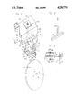
- FIG. 1 is a perspective view showing one of a pair of cultivator disc assemblies with parts broken away and the lateral T-bar clamping means shown in phantom, and forming part of a cultivator or other land tilling implement.
- FIG. 2 is a perspective view of the T-bar clamp shown in phantom in FIG. 1.
- FIG. 3 is a front sectional view with parts broken away of the T-bar clamp of FIG. 2 in clamping position.
- the improved cultivator disc positioning means of the invention comprises an individual disc 1, which is rotatably mounted at the base of a vertical support shaft 2, which extends upwardly through an opening 3 in lateral adjustment bracket 4.
- the vertical support shaft 2 extends further upwardly through an opening 5 in an angle adjustment bracket 6, which is pivotally supported on the upper surface of the lateral adjustment bracket 4.
- the lateral adjustment bracket 4 supports the support shaft 2 on which the cultivator disc 1 is mounted.
- the lateral adjustment bracket 4 extends into, and is supported by, a lateral housing 7 in the main frame 8 of a cultivator disc assembly.
- the support-shaft 2 is provided with a plurality of vertically disposed, horizontal openings 9 and is supported by the angle adjustment bracket 6 by means of a height adjustment bolt 10 which extends horizontally through one of the openings 9 in the support shaft 2 and through opposed openings 11 in a collar 12 on the angle adjustment bracket 6.
- the lateral adjustment bracket 4 is disposed just below and supports the angle adjustment bracket 6, and is provided with a plurality of horizontally disposed, vertical openings 13 (shown in phantom) positioned at predetermined horizontal angles to receive an angle pilot pin 14 which extends vertically downwardly through an opening 15 in the angle adjustment bracket 6 through one of the aligned openings 13 in the lateral adjustment bracket 4 to thereby fix the angular position of the support shaft 2 and its respective disc 1.
- Angle adjustment of each disc 1 is accomplished by first loosening angle locking bolt 16 on the angle adjustment bracket 6.
- Bolt 16 extends through a slot 17 in the angle adjustment bracket 6, into a threaded opening 17a in the lateral adjustment bracket 4, and when bolt 16 is loosened and angle pilot pin 14 is raised, the vertical support shaft 2 can be rotated to change the angle of disc 1 relative to direction of travel of the cultivator disc assembly.
- the angle pilot pin 14 is reinserted through the opening 15 through the aligned opening 13.
- the angle locking bolt 16 is then retightened in slot 17 to provide a firmly locked angle adjustment which cannot be thrown out during cultivating.
- Lateral adjustment is accomplished by sliding the lateral adjustment bracket 4 in the lateral housing 7 in the main frame 8.
- a fixed position is established by a lateral pilot pin 18 which extends downwardly through an opening 19 in the lateral housing 7 through one of a series of laterally spaced, vertical openings 20 in the lateral adjustment bracket 4.
- a T-bar 21 is disposed between two adjacent lateral housings 7, the crossbar of the inverted T-bar 21 nesting in grooves 22 cut transversely across the lateral housing 7.
- Stem 23 of the T-bar 21 extends upwardly between the lateral housing 7 through a clamp plate 24 resting on the top of the main frame 8, and is clamped in place by a clamping nut 25.
- a clamping nut 25 is required for lateral adjustment of each pair of cultivator discs of the subject invention.
- Vertical adjustment of the support shaft 2 is accomplished by removing the bolt 10 from the opposed openings 11 and one of the openings 9 in the vertical support shaft 2.
- the support shaft 2 can then be raised or lowered as desired in the collar 12 until the correct opening 9 is aligned with opposed openings 11 in the collar 12.
- the bolt 10 is then reinserted and fastened in place to complete the height adjustment.
Abstract
Description
Claims (11)
Priority Applications (1)
| Application Number | Priority Date | Filing Date | Title |
|---|---|---|---|
| US07/081,331 US4928774A (en) | 1987-08-04 | 1987-08-04 | Cultivator with improved disc positioning means |
Applications Claiming Priority (1)
| Application Number | Priority Date | Filing Date | Title |
|---|---|---|---|
| US07/081,331 US4928774A (en) | 1987-08-04 | 1987-08-04 | Cultivator with improved disc positioning means |
Publications (1)
| Publication Number | Publication Date |
|---|---|
| US4928774A true US4928774A (en) | 1990-05-29 |
Family
ID=22163500
Family Applications (1)
| Application Number | Title | Priority Date | Filing Date |
|---|---|---|---|
| US07/081,331 Expired - Fee Related US4928774A (en) | 1987-08-04 | 1987-08-04 | Cultivator with improved disc positioning means |
Country Status (1)
| Country | Link |
|---|---|
| US (1) | US4928774A (en) |
Cited By (9)
| Publication number | Priority date | Publication date | Assignee | Title |
|---|---|---|---|---|
| US5078216A (en) * | 1990-12-24 | 1992-01-07 | Virgil Dick | Combination tillage apparatus |
| US5259460A (en) * | 1989-10-19 | 1993-11-09 | Evers Research B.V. | Device for working the ground |
| US5458203A (en) * | 1989-10-19 | 1995-10-17 | Evers Research B.V. | Device for working the ground |
| US5497716A (en) * | 1994-04-29 | 1996-03-12 | Shoup; Kenneth E. | Mechanism for clearing crop residue |
| WO2004056169A2 (en) * | 2002-12-19 | 2004-07-08 | Amazonen-Werke H. Dreyer Gmbh & Co. Kg | Method for sowing seeds |
| EP1506703A3 (en) * | 2003-08-09 | 2005-07-20 | Amazonen-Werke H. Dreyer GmbH & Co. KG | disk apparatus |
| US8413739B2 (en) * | 2011-08-22 | 2013-04-09 | Deere & Company | Agricultural implement standard mount |
| FR3025970A1 (en) * | 2014-09-23 | 2016-03-25 | Kuhn Huard Sa | SOIL WORKING MODULE WITH A DEFLECTOR DISK HAVING AN IMPROVED ADJUSTMENT MEANS AND AGRICULTURAL MACHINE HAVING AT LEAST ONE MODULE ACCORDING TO THE INVENTION |
| US11707009B2 (en) | 2020-06-24 | 2023-07-25 | Accura FLow, LLC | Cultivator |
Citations (17)
| Publication number | Priority date | Publication date | Assignee | Title |
|---|---|---|---|---|
| US556356A (en) * | 1896-03-17 | Disk harrow | ||
| US796942A (en) * | 1904-08-26 | 1905-08-08 | Frank W Stafford | Cultivator attachment. |
| US1500367A (en) * | 1919-07-12 | 1924-07-08 | Ji Case Threshing Machine Co | Implement frame |
| US2430434A (en) * | 1941-10-16 | 1947-11-04 | Case Co J I | Clamping device for tool standards |
| US2577952A (en) * | 1945-07-02 | 1951-12-11 | Enoch A Davis | Disk plow |
| US2676527A (en) * | 1950-08-30 | 1954-04-27 | Howard W Reustle | Cultivator attachment for tractors |
| US2790367A (en) * | 1953-09-23 | 1957-04-30 | William E Simmons | Cultivator disk gangs |
| US2829577A (en) * | 1953-12-28 | 1958-04-08 | David Brown Tractors Eng Ltd | Disc poughs |
| US2973819A (en) * | 1958-06-13 | 1961-03-07 | William E Simmons | Mounting and adjustment means for ground working implements |
| US3244237A (en) * | 1964-06-03 | 1966-04-05 | Case Co J I | Means adjustably connecting an earth working disk to a standard |
| US4009759A (en) * | 1975-03-26 | 1977-03-01 | Ernst Arnold E | Cultivator apparatus |
| US4295532A (en) * | 1979-11-02 | 1981-10-20 | Acra-Plant, Inc. | Planter with cooperating trash clearing discs |
| US4550122A (en) * | 1983-07-18 | 1985-10-29 | Fleischer Manufacturing, Inc. | Attachment for removing residue in front of a planter |
| US4607705A (en) * | 1983-12-27 | 1986-08-26 | Tebben John A | Row crop cultivator including disk and setting indicator therefor |
| US4650005A (en) * | 1983-12-27 | 1987-03-17 | Tebben John A | Row crop cultivator with setting indicator |
| US4738316A (en) * | 1986-08-11 | 1988-04-19 | Deere & Company | Adjustable shank mounting for an earthworking tool |
| US4815544A (en) * | 1987-02-24 | 1989-03-28 | Allied Products Corporation | Cultivator disc adjuster |
-
1987
- 1987-08-04 US US07/081,331 patent/US4928774A/en not_active Expired - Fee Related
Patent Citations (17)
| Publication number | Priority date | Publication date | Assignee | Title |
|---|---|---|---|---|
| US556356A (en) * | 1896-03-17 | Disk harrow | ||
| US796942A (en) * | 1904-08-26 | 1905-08-08 | Frank W Stafford | Cultivator attachment. |
| US1500367A (en) * | 1919-07-12 | 1924-07-08 | Ji Case Threshing Machine Co | Implement frame |
| US2430434A (en) * | 1941-10-16 | 1947-11-04 | Case Co J I | Clamping device for tool standards |
| US2577952A (en) * | 1945-07-02 | 1951-12-11 | Enoch A Davis | Disk plow |
| US2676527A (en) * | 1950-08-30 | 1954-04-27 | Howard W Reustle | Cultivator attachment for tractors |
| US2790367A (en) * | 1953-09-23 | 1957-04-30 | William E Simmons | Cultivator disk gangs |
| US2829577A (en) * | 1953-12-28 | 1958-04-08 | David Brown Tractors Eng Ltd | Disc poughs |
| US2973819A (en) * | 1958-06-13 | 1961-03-07 | William E Simmons | Mounting and adjustment means for ground working implements |
| US3244237A (en) * | 1964-06-03 | 1966-04-05 | Case Co J I | Means adjustably connecting an earth working disk to a standard |
| US4009759A (en) * | 1975-03-26 | 1977-03-01 | Ernst Arnold E | Cultivator apparatus |
| US4295532A (en) * | 1979-11-02 | 1981-10-20 | Acra-Plant, Inc. | Planter with cooperating trash clearing discs |
| US4550122A (en) * | 1983-07-18 | 1985-10-29 | Fleischer Manufacturing, Inc. | Attachment for removing residue in front of a planter |
| US4607705A (en) * | 1983-12-27 | 1986-08-26 | Tebben John A | Row crop cultivator including disk and setting indicator therefor |
| US4650005A (en) * | 1983-12-27 | 1987-03-17 | Tebben John A | Row crop cultivator with setting indicator |
| US4738316A (en) * | 1986-08-11 | 1988-04-19 | Deere & Company | Adjustable shank mounting for an earthworking tool |
| US4815544A (en) * | 1987-02-24 | 1989-03-28 | Allied Products Corporation | Cultivator disc adjuster |
Cited By (11)
| Publication number | Priority date | Publication date | Assignee | Title |
|---|---|---|---|---|
| US5259460A (en) * | 1989-10-19 | 1993-11-09 | Evers Research B.V. | Device for working the ground |
| US5458203A (en) * | 1989-10-19 | 1995-10-17 | Evers Research B.V. | Device for working the ground |
| US5078216A (en) * | 1990-12-24 | 1992-01-07 | Virgil Dick | Combination tillage apparatus |
| US5497716A (en) * | 1994-04-29 | 1996-03-12 | Shoup; Kenneth E. | Mechanism for clearing crop residue |
| WO2004056169A2 (en) * | 2002-12-19 | 2004-07-08 | Amazonen-Werke H. Dreyer Gmbh & Co. Kg | Method for sowing seeds |
| WO2004056169A3 (en) * | 2002-12-19 | 2005-03-10 | Amazonen Werke Dreyer H | Method for sowing seeds |
| EP1506703A3 (en) * | 2003-08-09 | 2005-07-20 | Amazonen-Werke H. Dreyer GmbH & Co. KG | disk apparatus |
| US8413739B2 (en) * | 2011-08-22 | 2013-04-09 | Deere & Company | Agricultural implement standard mount |
| FR3025970A1 (en) * | 2014-09-23 | 2016-03-25 | Kuhn Huard Sa | SOIL WORKING MODULE WITH A DEFLECTOR DISK HAVING AN IMPROVED ADJUSTMENT MEANS AND AGRICULTURAL MACHINE HAVING AT LEAST ONE MODULE ACCORDING TO THE INVENTION |
| EP3000296A1 (en) | 2014-09-23 | 2016-03-30 | Kuhn-Huard S.A. | Soil-working module with a deflector device provided with improved adjustment means and agricultural machine having at least one such module |
| US11707009B2 (en) | 2020-06-24 | 2023-07-25 | Accura FLow, LLC | Cultivator |
Similar Documents
| Publication | Publication Date | Title |
|---|---|---|
| US4738316A (en) | Adjustable shank mounting for an earthworking tool | |
| US4819737A (en) | Row crop cultivator | |
| US4461355A (en) | Cultivator row unit with ridger/bedder implement | |
| US4102406A (en) | Ground conditioning device and method of conditioning soil | |
| US4585073A (en) | Rotary disk tool assembly and implements | |
| AU2017208365B2 (en) | A plough assembly | |
| MXPA97006962A (en) | Rear bar culture implement | |
| US3223178A (en) | Disc harrow | |
| US4928774A (en) | Cultivator with improved disc positioning means | |
| US5452768A (en) | Gauge depth control for soil tillage implement | |
| US4729435A (en) | Subsoil tilling implement | |
| US4560011A (en) | Cultivator row unit with ridger/bedder implement | |
| US3935906A (en) | Adjustable height soil conditioner with frame extending rearwardly from cultivating implement | |
| US3998275A (en) | Earthworking implement and row guide apparatus | |
| US4660653A (en) | Rotary disk tool assembly and implements | |
| US3991831A (en) | Combination post-plowing cultivating implement and field drag | |
| US4485878A (en) | Shield unit for cultivators | |
| CA1097976A (en) | Tool mounting with member locatable in first and second position between standard and frame | |
| US3642333A (en) | Clamp | |
| US5785129A (en) | Row crop cultivator having a fixed depth of penetration | |
| KR101054606B1 (en) | A hiller easy of adjust high and low of ridge | |
| US2646738A (en) | Cultivator | |
| US4142588A (en) | Lister stabilizer | |
| US3151683A (en) | Cultivator attachment for rotary hoe | |
| US5316088A (en) | Rotary hoe mounting unit for row crop cultivator |
Legal Events
| Date | Code | Title | Description |
|---|---|---|---|
| AS | Assignment |
Owner name: PROTECH MANUFACTURING COMPANY, INC., R.R. 26, BOX Free format text: ASSIGNMENT OF ASSIGNORS INTEREST.;ASSIGNOR:BELL, DENNIS E.;REEL/FRAME:004777/0197 Effective date: 19871025 Owner name: PROTECH MANUFACTURING COMPANY, INC., A CORP. OF IN Free format text: ASSIGNMENT OF ASSIGNORS INTEREST;ASSIGNOR:BELL, DENNIS E.;REEL/FRAME:004777/0197 Effective date: 19871025 |
|
| AS | Assignment |
Owner name: LANDOLL CORPORATION, 1700 MAY STREET, MARYSVILLE, Free format text: ASSIGNMENT OF ASSIGNORS INTEREST.;ASSIGNOR:PROTECH MANUFACTURING COMPANY, INC.;REEL/FRAME:004873/0797 Effective date: 19881123 Owner name: LANDOLL CORPORATION, A KA CORP.,KANSAS Free format text: ASSIGNMENT OF ASSIGNORS INTEREST;ASSIGNOR:PROTECH MANUFACTURING COMPANY, INC.;REEL/FRAME:004873/0797 Effective date: 19881123 |
|
| REFU | Refund |
Free format text: REFUND OF EXCESS PAYMENTS PROCESSED (ORIGINAL EVENT CODE: R169); ENTITY STATUS OF PATENT OWNER: SMALL ENTITY |
|
| FPAY | Fee payment |
Year of fee payment: 4 |
|
| FPAY | Fee payment |
Year of fee payment: 8 |
|
| REMI | Maintenance fee reminder mailed | ||
| LAPS | Lapse for failure to pay maintenance fees | ||
| STCH | Information on status: patent discontinuation |
Free format text: PATENT EXPIRED DUE TO NONPAYMENT OF MAINTENANCE FEES UNDER 37 CFR 1.362 |
|
| FP | Lapsed due to failure to pay maintenance fee |
Effective date: 20020529 |