EP2999568B1 - Buse pour une machine de travail au laser et machine correspondante - Google Patents
Buse pour une machine de travail au laser et machine correspondante Download PDFInfo
- Publication number
- EP2999568B1 EP2999568B1 EP13732821.7A EP13732821A EP2999568B1 EP 2999568 B1 EP2999568 B1 EP 2999568B1 EP 13732821 A EP13732821 A EP 13732821A EP 2999568 B1 EP2999568 B1 EP 2999568B1
- Authority
- EP
- European Patent Office
- Prior art keywords
- nozzle
- laser machining
- radiation
- contrast section
- machining nozzle
- Prior art date
- Legal status (The legal status is an assumption and is not a legal conclusion. Google has not performed a legal analysis and makes no representation as to the accuracy of the status listed.)
- Active
Links
- 238000003754 machining Methods 0.000 title claims description 44
- 238000000034 method Methods 0.000 claims description 106
- 230000008569 process Effects 0.000 claims description 101
- 238000001514 detection method Methods 0.000 claims description 76
- 230000005855 radiation Effects 0.000 claims description 73
- 239000011248 coating agent Substances 0.000 claims description 23
- 238000000576 coating method Methods 0.000 claims description 23
- 230000000694 effects Effects 0.000 claims description 21
- 238000012544 monitoring process Methods 0.000 claims description 18
- 238000005286 illumination Methods 0.000 claims description 16
- 230000002745 absorbent Effects 0.000 claims description 9
- 239000002250 absorbent Substances 0.000 claims description 9
- RYGMFSIKBFXOCR-UHFFFAOYSA-N Copper Chemical compound [Cu] RYGMFSIKBFXOCR-UHFFFAOYSA-N 0.000 claims description 3
- 229910052802 copper Inorganic materials 0.000 claims description 3
- 239000010949 copper Substances 0.000 claims description 3
- 238000012545 processing Methods 0.000 description 65
- 239000007789 gas Substances 0.000 description 9
- 230000003287 optical effect Effects 0.000 description 8
- 238000010521 absorption reaction Methods 0.000 description 7
- 238000011156 evaluation Methods 0.000 description 5
- 238000011161 development Methods 0.000 description 4
- 239000000463 material Substances 0.000 description 4
- 238000005259 measurement Methods 0.000 description 4
- 229910001220 stainless steel Inorganic materials 0.000 description 3
- 239000010935 stainless steel Substances 0.000 description 3
- PXHVJJICTQNCMI-UHFFFAOYSA-N Nickel Chemical compound [Ni] PXHVJJICTQNCMI-UHFFFAOYSA-N 0.000 description 2
- XUIMIQQOPSSXEZ-UHFFFAOYSA-N Silicon Chemical compound [Si] XUIMIQQOPSSXEZ-UHFFFAOYSA-N 0.000 description 2
- 229910000746 Structural steel Inorganic materials 0.000 description 2
- 230000004913 activation Effects 0.000 description 2
- 230000008901 benefit Effects 0.000 description 2
- 230000009849 deactivation Effects 0.000 description 2
- 238000000605 extraction Methods 0.000 description 2
- 238000003698 laser cutting Methods 0.000 description 2
- 238000004519 manufacturing process Methods 0.000 description 2
- 229910052710 silicon Inorganic materials 0.000 description 2
- 239000010703 silicon Substances 0.000 description 2
- 230000003595 spectral effect Effects 0.000 description 2
- 238000011144 upstream manufacturing Methods 0.000 description 2
- 229910000530 Gallium indium arsenide Inorganic materials 0.000 description 1
- 229910000831 Steel Inorganic materials 0.000 description 1
- 230000002411 adverse Effects 0.000 description 1
- 230000033228 biological regulation Effects 0.000 description 1
- 230000000903 blocking effect Effects 0.000 description 1
- 238000009529 body temperature measurement Methods 0.000 description 1
- 238000010276 construction Methods 0.000 description 1
- 238000001816 cooling Methods 0.000 description 1
- 239000000498 cooling water Substances 0.000 description 1
- 230000008878 coupling Effects 0.000 description 1
- 238000010168 coupling process Methods 0.000 description 1
- 238000005859 coupling reaction Methods 0.000 description 1
- 230000001419 dependent effect Effects 0.000 description 1
- 238000013461 design Methods 0.000 description 1
- 238000010586 diagram Methods 0.000 description 1
- 238000005516 engineering process Methods 0.000 description 1
- 238000010438 heat treatment Methods 0.000 description 1
- 230000002452 interceptive effect Effects 0.000 description 1
- 239000002184 metal Substances 0.000 description 1
- 229910052751 metal Inorganic materials 0.000 description 1
- 238000004021 metal welding Methods 0.000 description 1
- 229910052759 nickel Inorganic materials 0.000 description 1
- 230000001681 protective effect Effects 0.000 description 1
- 239000004065 semiconductor Substances 0.000 description 1
- 230000035945 sensitivity Effects 0.000 description 1
- 239000007787 solid Substances 0.000 description 1
- 239000010959 steel Substances 0.000 description 1
- 230000001629 suppression Effects 0.000 description 1
- XLYOFNOQVPJJNP-UHFFFAOYSA-N water Substances O XLYOFNOQVPJJNP-UHFFFAOYSA-N 0.000 description 1
- 238000003466 welding Methods 0.000 description 1
Images
Classifications
-
- B—PERFORMING OPERATIONS; TRANSPORTING
- B23—MACHINE TOOLS; METAL-WORKING NOT OTHERWISE PROVIDED FOR
- B23K—SOLDERING OR UNSOLDERING; WELDING; CLADDING OR PLATING BY SOLDERING OR WELDING; CUTTING BY APPLYING HEAT LOCALLY, e.g. FLAME CUTTING; WORKING BY LASER BEAM
- B23K26/00—Working by laser beam, e.g. welding, cutting or boring
- B23K26/02—Positioning or observing the workpiece, e.g. with respect to the point of impact; Aligning, aiming or focusing the laser beam
- B23K26/03—Observing, e.g. monitoring, the workpiece
- B23K26/032—Observing, e.g. monitoring, the workpiece using optical means
-
- B—PERFORMING OPERATIONS; TRANSPORTING
- B23—MACHINE TOOLS; METAL-WORKING NOT OTHERWISE PROVIDED FOR
- B23K—SOLDERING OR UNSOLDERING; WELDING; CLADDING OR PLATING BY SOLDERING OR WELDING; CUTTING BY APPLYING HEAT LOCALLY, e.g. FLAME CUTTING; WORKING BY LASER BEAM
- B23K26/00—Working by laser beam, e.g. welding, cutting or boring
- B23K26/14—Working by laser beam, e.g. welding, cutting or boring using a fluid stream, e.g. a jet of gas, in conjunction with the laser beam; Nozzles therefor
- B23K26/1462—Nozzles; Features related to nozzles
Definitions
- the invention relates to a laser processing nozzle for a laser processing device, wherein the laser processing device for process monitoring has a detection device for detecting radiation of a process region defined by the laser processing nozzle. Furthermore, the invention relates to a laser processing device with such a laser processing nozzle and to a method for starting up such a laser processing nozzle on the laser processing device.
- an off-axis decoupling the radiation of the machining process is observed from a detection direction which extends at an angle of greater than 10 ° to the laser beam axis.
- the detection direction is at an angle of less than 10 ° to the laser beam axis. From a coaxial coupling is spoken when the detection direction is parallel to the laser beam axis.
- a detection of the process light through the laser processing nozzle has proven itself, since the process region can be viewed particularly freely from this direction.
- An example of a detection device on a CO 2 laser cutting system in which a detection of the process light through a laser processing nozzle, is performed by the DE 10 2011 003 717 A1 described.
- the decoupling of the radiation emitted or reflected by the process area takes place by means of a partially transparent deflecting mirror.
- the incident CO 2 laser light is reflected at the deflection mirror.
- the radiation from the process area in a wavelength range of 550 to 2000 nm can pass through the deflection mirror.
- the camera detects the radiation at an observation wavelength, e.g. B. in the visible or near-infrared wavelength range.
- the images of the camera can be used for process monitoring or control.
- a laser device with a gas nozzle is known, to which a cooling system is attached.
- the heat absorbed by the gas nozzle is detected by means of a temperature measurement of the cooling water.
- the sensitivity of the measuring device is increased by a heat absorbing layer on the inner surface of the gas nozzle.
- the invention has set itself the task, the signal quality of the detected radiation of the process area at least one To improve observation wavelength.
- the object is achieved by a laser processing nozzle having the features of claim 1.
- the surface of the laser processing nozzle has at least one contrast section which has a scattering and / or absorbing effect at least for radiation or light at an observation wavelength suitable for process monitoring by a detection device.
- a suitable observation wavelength is a wavelength at which monitoring of a laser processing process by means of a detection device allows conclusions to be drawn about the processing process. In particular, therefore, a possible observation wavelength in the range between 300 to 3000 nm, which includes both the visible and the near-infrared spectral range.
- the laser processing nozzle has a metallic base body, on the surface of which, at least in the contrast section, a coating absorbing at least at an observation wavelength between 300 and 1100 nm and / or for radiation at least at an observation wavelength between 900 and 1700 nm is applied and / or a scattering surface structure is formed.
- a metallic base body in particular of copper, has a good resistance to the thermal and mechanical stresses during laser processing.
- a nozzle with a metallic base body is suitable for use together with other sensors of laser processing equipment, such as a capacitive distance sensor.
- an absorbing coating of the contrast section at least at the observation wavelength, has a higher degree of absorption than the uncoated material surface of the metallic base body.
- the process lighting is detected in a process Wavelength between 300 and 1100 nm, as well-suited for this wavelength range silicon-based detectors are available. Likewise preferably, the detection of a wavelength between 900 to 1700 nm. For this wavelength range z. B. InGaAs-based detectors well suited ..
- an optical detector, sensor or an image detection device of the detection device not only detects radiation at exactly one wavelength. Rather, depending on the type of detector and possibly upstream filter - i. d. R. detects a narrow wavelength range around an observation wavelength.
- both a scattering and an absorbing effect on the radiation emanating from the process area at an observation wavelength ensures that the radiation which occurs at the contrast section on the nozzle can be reflected to the detection device to a much lesser extent. An occurrence of disturbing reflections is reduced. Due to the optical properties of the contrast section according to the invention, the image of the contrast section can be distinguished very well from the image of the process area in the images of the detection device.
- the scattering effect of the contrast section can be achieved for example by surface structuring.
- a surface structuring can be produced relatively inexpensively.
- the degree of roughness preferably corresponds at least approximately to the magnitude of the observation wavelength.
- an absorbing effect in the context of the invention results in particular if the absorption coefficient for radiation is greater than 0.3 at least at the observation wavelength.
- the absorption coefficient for radiation is preferably greater than 0.5 at at least the observation wavelength, more advantageously the absorption coefficient for radiation of the observation wavelength is greater than 0.7 or even greater than 0.9. The emergence of disturbing reflections at the contrast section is effectively prevented in this way.
- the contrasting portion at least at the observation wavelength, has a reflectance that is different from, preferably smaller, the reflectance of the surface of the workpiece that is also detected by the detection device.
- the reflectance difference is a value of at least 0.1, preferably at least 0.3 or even at least 0.5. Thanks to this measure, the recording of the detection device results in a high contrast between the imaged part of the nozzle and the imaged workpiece surface.
- z. B the diameter of the process-facing nozzle opening reliably checked or measured very accurately.
- the contrast portion of the nozzle for radiation at the observation wavelength has a reflectance which differs from the reflectance of the surface of structural steel and / or stainless steel by at least 0.1, preferably at least 0.3 or even at least 0.5, in particular smaller by these values is as this.
- the contrast section of the nozzle is preferably designed such that, compared to a nozzle without a contrast section, a smaller proportion of the radiation can reach the detection device by reflection at the nozzle surface at least at the observation wavelength. In particular, this is achieved by a reflectance of the contrast section according to the above statements with respect to the detection range of the detection device.
- the signal quality of the radiation emanating from the process area and detected by a detection device is particularly effectively improved in the case of a preferred embodiment in that the contrast section is arranged on the nozzle surface in such a way that radiation from the process area can impinge directly on the contrast section.
- the contrast section is preferably arranged on the nozzle surface such that the contrast section can be arranged in the detection or recording area of a detection device for detecting radiation of a process area defined by the laser nozzle.
- the detection device is not or not only for direct viewing of the immediate laser processing process but (also) insofar as for process monitoring that by means of the detection device z. B. the state or the dimensions of the nozzle can be checked. Consequently, due to the contrast section arranged in the receiving area of the detection device, a measurement or checking of the imaged part of the mounted nozzle by the detection device during the laser processing can be carried out with a higher accuracy and reliability.
- the contrast section is arranged on the nozzle outer surface at least on that side which faces the detection device.
- the laser beam and additional process gases can be guided to the process area.
- it has a nozzle channel which extends between two nozzle openings.
- a nozzle opening faces the process area, and a nozzle opening faces away from the process area.
- the nozzle is designed such that the radiation of the process area can be detected by means of the detection device through the nozzle channel extending between two nozzle openings.
- the nozzle is therefore suitable for use on a laser processing device with coaxial or quasi-coaxial extraction of the process light to be detected.
- the contrast section is preferably arranged on the nozzle channel wall such that it is visible starting from the nozzle opening which faces away from the process area during operation.
- the nozzle is consequently constructed in such a way that radiation emitted or reflected at the contrast section can escape from the nozzle through the process-facing nozzle opening, contrary to the detection direction (in the case of coaxial decoupling parallel to the laser beam axis or to the course of the nozzle channel) and thus to the detection device could arrive.
- the nozzle opening facing away from the process is larger than the opening width of the nozzle inner surface in the region of the contrast section, and no further constrictions are present between the nozzle opening facing away from the process and the contrast section, blocking the view in the detection direction on the contrast section. Thanks to this measure, the contrast section for a coaxial detection device is visible and increases due to its contrast opposite the process area z. B. the readability of the recording of the detection device.
- the contrast section by means of a coating has an absorbing effect for radiation at least at the observation wavelength.
- the coating may be selected specifically for the desired absorbing effect, and the nozzle may be further constructed of one or more other materials that meet other nozzle requirements such as temperature resistance, etc.
- the absorbent coating is preferably formed as a smooth coating, which has the advantage that the contrast section has no disturbing influences on the gas flow through the nozzle due to its smooth surface.
- At least one part of the outer surface of the nozzle facing the process area during operation does not have a coating like the contrast section.
- the part of the nozzle outer surface which faces the workpiece during machining is exposed to particular emissions. Both the thermal and the mechanical stress z. B. by splashes are particularly high there. If an absorbent coating would also be applied to this part of the nozzle, this would have in addition to the absorbing effect also a particularly high resistance force against thermal and mechanical stresses. This makes it difficult to choose a suitable coating.
- the distance between the nozzle and a workpiece is often determined by capacitance measurements between the nozzle and the workpiece. A coating of the nozzle outer surface may have undesirable effects on the capacitance measurements. In particular, it is advantageous against this background if the entire outer surface of the nozzle does not have a coating corresponding to the contrast section.
- the choice of the wavelength at which a detection device the Process area is dependent on various aspects. For example, it is decisive which faulty processes are to be determined first and foremost.
- radiation of the process area at different wavelengths can also be detected at one and the same laser processing device. For this purpose, several separate detection devices may be present. On the one hand, radiation can be detected, which is only reflected at the process area. On the other hand, radiation can be detected which is produced and emitted in the process area due to the laser processing process.
- the emitted process light, the so-called process lighting is particularly suitable for making determinations about possible process failures in the process area.
- the absorbing effect of the contrast section therefore reduces the occurrence of disturbing reflections of emitted process radiation, which is particularly well suited for process monitoring.
- the contrast section for radiation at an observation wavelength is absorbent, whereas the contrast section does not absorb radiation with a wavelength of greater than 2000 nm or only to a small extent.
- interfering influences of the laser beam of the laser processing device for which the laser nozzle is provided are reduced to the laser nozzle when the contrast section at the wavelength of the Laser beam does not or only to a small extent absorbs.
- the contrast portion is therefore not or only slightly absorbable for radiation at a wavelength of about 10.6 ⁇ m and / or about 1.03 ⁇ m.
- the contrast section has an absorption factor of less than 0.5, in particular less than 0.3.
- No absorbing effect is present, in particular, when the absorption coefficient of the surface is less than 0.1. Thanks to this measure, the contrast section reflects a considerable part of the laser beam or the heat radiation of the process area, which is not needed for process monitoring. Excessive heating of the nozzle is counteracted.
- Laser processing nozzles are usually consumables. They must be replaced several times over the life of a laser processing device. Moreover, they are usually designed especially for the respective processing tasks. Consequently, in the case of the nozzle according to the invention, it is advantageously a replaceable nozzle.
- the nozzle is preferably in one piece, in particular, apart from a possible absorbent coating, of the same material. In a preferred embodiment, the nozzle is formed without an integrated water supply.
- the laser processing nozzle as an essentially rotationally symmetrical component is advantageous in terms of manufacturing technology. An inexpensive production as a turned part is made possible.
- the laser processing nozzle can be provided, for example, in the region of the process-facing nozzle opening with an external thread.
- the contrast section is at least partially disposed on a conical portion of its inner surface or the nozzle channel wall.
- the contrast section can thus serve to shape the process gas flow and is also clearly visible in the detection direction. In particular, it runs at an angle of inclination between 5 ° and 15 ° to the course of the nozzle channel or the laser beam axis or detection direction.
- the contrast section is arranged such that viewed through the nozzle the contrast section surrounds the nozzle opening, which faces the process area during operation.
- the contrast section can consequently be represented in the edge area of the image of the process area resulting in the detection device and can easily be used for the measurement of the nozzle during the evaluation or may possibly be disregarded.
- an advantageous arrangement results for an evaluation of the detector recordings when the contrast section viewed through the nozzle directly adjoins the nozzle opening.
- the diameter of the nozzle opening can be determined particularly accurately and reliably due to the increased contrast between the contrast section and the nozzle opening.
- the contrast section is arranged at least on this cylindrical section in the case of a design of a nozzle in which the process-facing nozzle opening adjoins a cylindrical section of the nozzle channel.
- a laser processing device has a nozzle with a contrast section and a detection device for detecting radiation of a process region defined by the nozzle at at least one observation wavelength, wherein the contrast region absorbs the radiation at least at the observation wavelength and / or scatters.
- the detection device preferably carries out a coaxial or at least quasi-coaxial observation of the process area through the nozzle.
- the laser processing device has a lighting device by means of which at least the process area defined by the nozzle can be illuminated.
- the illumination device can illuminate the process area laterally, ie not parallel to the laser beam axis.
- the contrast section of the nozzle acts scattering or absorbing for the radiation of the illumination device at at least one wavelength, which at the same time corresponds to an observation wavelength of the detection device. This disturbing light or radiation reflections are reduced due to the lighting device on the surface of the nozzle or even completely prevented.
- Nozzle can be illuminated through, d. H. the illumination is coaxial or at least quasi-coaxial. A direct and unhindered illumination of the process area is guaranteed. It is also advantageous in the coaxial or quasi-coaxial arrangement of the illumination device if the contrast section has a scattering and / or absorbing effect on radiation of the illumination device at a wavelength which at the same time corresponds to an observation wavelength. A contrast section absorbing the radiation at at least one detected wavelength of the illumination device has the consequence that the illuminated contrast section appears darker and thereby the contrast to the process area is increased. On the other hand, a scattering contrast section has the effect that due to the reflected radiation of the illuminated contrast section reflected back, it appears brighter and thereby the contrast to the process area is increased.
- the nozzle-facing surface of the workpiece is also illuminated by the illumination device and arrives at the workpiece processing in the receiving area of the detection device.
- the contrast section of the nozzle at least for radiation of the illumination device at a wavelength which also corresponds to an observation wavelength, a reflectance which differs from the reflectance of the workpiece surface, in particular is smaller than this.
- the reflectance difference has a value of at least 0.1, preferably at least 0.3 or even at least 0.5.
- the contrasting portion for radiation of the illumination device at a wavelength which also corresponds to an observation wavelength has a reflectance which is at least 0.1, preferably at least 0.3 or even at least, of the reflectance of the surface of structural steel and / or stainless steel 0.5 differs, especially around these values is smaller than this.
- an activation / deactivation unit is provided by means of which a process monitoring by the detection device can be activated and deactivated, depending after whether or not a built-in nozzle has an expected contrast portion. In this way, it is ensured that the process monitoring does not take place with a nozzle, which can not guarantee a sufficient quality of the signal of the detection device for lack of contrast section.
- a detection device in a method for starting up a nozzle on a laser processing device, after the nozzle is attached to the processing device, it is checked by means of a detection device whether the surface of the nozzle has an expected contrast section, which in the detection direction for the Detection device is visible and at least for radiation at an observation wavelength of the detection device has a scattering and / or absorbing effect.
- process monitoring by the detection device for the subsequent laser processing using the nozzle is deactivated or not activated at all.
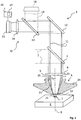
- FIG. 1 shows a laser processing device 1, which is used in particular for laser cutting or welding of metal workpieces, such as metal sheets.
- the laser processing device 1 is part of a laser processing system which comprises, for example, a CO 2 laser or a solid-state laser for generating a laser beam 2 .
- the laser beam 2 is supplied to the laser processing device 1 by means of a beam guide not shown.
- a nozzle channel 5 of a laser machining nozzle 6 When passing through the nozzle channel 5 of the laser beam 2 runs along a laser beam axis 9.
- the nozzle 6 is on attached to a nozzle receptacle, which is not shown for clarity in the figures.
- more details of the processing device 1, such. B. a supply of process gases, which can be fed via the nozzle to the process area 7, are not shown for clarity in the figures.
- the position of the process area 7 on the workpiece 8 can be varied by a relative movement by means of movement devices, likewise not shown, between the laser steel 2 and the workpiece 8.
- the laser processing device 1 has a detection device 10 for detecting radiation, which is reflected or emitted by the process area 7.
- the radiation of the process area 7 can be detected in a detection direction through the nozzle 6.
- the detection direction runs in the region of the nozzle 6 parallel to the laser beam axis 9 and in FIG. 1 from top down.
- the radiation of the process area 7 is consequently decoupled coaxially.
- the course of the detected radiation is in FIG. 1 represented by solid lines 11 .
- the decoupling via the partially transparent deflecting mirror 3, which z. B. for radiation in a wavelength range 500 to 2000 nm is transparent, but the laser light (CO 2 : 10.6 microns, solid: eg., 1.03 microns) reflected.
- a decoupling can also be done with the help of a scraper, Riefen- or perforated mirror.
- a further deflecting mirror 12 In order to convey the decoupled radiation to an optical detector of the detection device 10, a further deflecting mirror 12, a partially transparent deflecting mirror 13 and a lens 14 are provided.
- an optical detector or optical sensor is a spatially resolving Nahinfrarot camera 15, which z. B. based on silicon as a semiconductor material and is operated with an upstream bandpass filter in the near-infrared spectral range.
- an evaluation unit 16 is provided for evaluation of the camera recordings.
- another optical sensor can be used, which z. B. provides integrated intensity values over the detected area.
- the inner surface of the nozzle 6 or the nozzle channel wall has, starting from a process-remote nozzle opening 20, a conical section 21 .
- a short cylindrical section 22 extends between the conical section 21 and the process-facing nozzle opening 23.
- FIG. 1 It can be seen that at least part of the inner surface of the nozzle 6 or the nozzle channel wall, starting from the process-facing nozzle opening 20, in particular in the viewing direction parallel to the course of the nozzle channel 5, ie in the detection direction, is visible.
- the conical section 21 and the cylindrical section 22 of the nozzle channel wall form a contrast section 25.
- It is provided with a coating which, compared to the uncoated surface of the base body 24 of the nozzle 6 for radiation has an absorbing effect at least at the observation wavelength. Thanks to the absorbent coating, radiation is at least significantly prevented at least at the observation wavelength, which, starting from the process area 7, directly hits the contrast section 25 , is reflected there. For the reflected radiation would reach the camera 15 via the focusing lens 4, etc., and adversely affect the signal quality of the process images.
- the entire outer surface of the nozzle 6 has no coating.
- the nozzle 6 is well suited for use with a capacitive distance sensor, not shown.
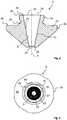
- the nozzle 6 is in FIG. 1 slightly distorted. In detail, the nozzle 6 is therefore further based on the FIGS. 2 to 3 which show true-to-scale illustrations of the nozzle 6.
- the nozzle 6 has a metallic base body 24 made of copper.
- the nozzle channel 5, which is guided centrally through the main body 24, is designed to be rotationally symmetrical about the laser beam axis 9.
- an external thread 35 is provided, by means of which the nozzle 6 can be replaceably fastened to the nozzle receptacle, not shown, of the processing device 1.
- an outer edge 26 of the nozzle 6 is polygonal-shaped to provide an opportunity to attack a tool for loosening or tightening the nozzle 6 to the nozzle holder.
- the nozzle openings 20, 23 and the entire nozzle channel 5 have circular cross-sections.
- the process-remote nozzle opening 20 has, for example, a diameter of 7 to 10 mm, while the process-facing nozzle opening 23, for example, has a diameter of 0.7 to 3.0 mm.
- the conical section 21 extends at an angle of inclination of approximately 11 ° with respect to the course of the nozzle channel 5.
- the nozzle 6 is shown in a plan view parallel to the course of the nozzle channel 5 on the process-facing nozzle opening 20. From this viewing direction, which corresponds to the detection direction of the detection device 10, the contrast section 25 completely surrounds the process-facing nozzle opening 23. By a dashed circle 27 , the area recorded by the camera 15 is indicated. In this receiving region 27, the contrast section 25 forms the edge region immediately adjacent to the nozzle opening 20.
- nozzle 6 which has an absorbent coating at least almost on the entire nozzle channel wall. The remaining surface of the nozzle 6, however, has no coating.
- the contrast section 25 is preferably provided with radiation at the observation wavelength absorbing coating which is not or only in the case of radiation having a wavelength greater than 2000 nm is absorbent to a small extent.
- FIG. 4 a second nozzle 6 is shown extending from the in the FIGS. 1 to 3 only differs in that the nozzle channel wall formed as a contrast section 25 instead of an absorbent coating has a surface structure which achieves a scattering effect at least for the observation wavelength.
- the nozzle 6 is according to FIG. 4 identical to the nozzle 6 according to the FIGS. 1 to 3 built up.
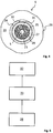
- Steps of a method for starting up a nozzle 6 are listed on the laser processing device 1.
- the nozzle 6 is attached to the nozzle holder of the laser processing device 1.
- it is checked by means of the detection device 10 whether the inner surface of the nozzle 6 has an expected contrast section 25.
- a process monitoring using the detection device 10 for the subsequent laser processing using the checked nozzle 6 is activated or not deactivated. Otherwise, process monitoring is deactivated or not activated.
- the evaluation unit 16 has an in FIG. 1 indicated activation / deactivation unit 17 .
- the monitoring of the process area 7 takes place at an observation wavelength between, for example, 300 and 1100 nm.
- the laser processing device 1 can comprise a detection device 10 for monitoring at another observation wavelength between, for example, 900 and 1700 nm. Consequently, the contrast section 25 of the nozzle 6 advantageously has an absorbing effect, in particular by an absorbing coating, for radiation at least at the respective observation wavelengths.
- the laser processing device 1 can also have an illumination device 18 , by means of which at least the process region 7 can be illuminated.
- an illumination device 18 is indicated, by means of which the process area 7 can be illuminated through the nozzle 6.
- the course of the illumination light is in FIG. 1 indicated by dashed lines 19 . So that the signal quality of the detection device 10 is increased due to the illumination, the illumination with radiation should take place at least at a wavelength which corresponds to the observation wavelength of the detection device 10.
Claims (13)
- Buse (6) d'usinage au laser destinée à un dispositif (1) d'usinage au laser, ledit dispositif (1) d'usinage au laser étant muni, en vue de la surveillance de processus, d'un dispositif de détection (10) affecté à la détection de rayonnement d'une zone d'opérations (7) bien définie par ladite buse (6) d'usinage au laser, caractérisée par le fait que ladite buse (6) d'usinage au laser présente un corps de base (24) en métal, notamment en du cuivre, sur la surface duquel est déposé un revêtement absorbant un rayonnement au moins en présence d'une longueur d'ondes d'observation comprise entre 300 et 1 100 nm et/ou un rayonnement au moins en présence d'une longueur d'ondes d'observation comprise entre 900 et 1 700 nm, et/ou est ménagée une structure superficielle diffusive, de manière à former une zone de contraste (25).
- Buse (6) d'usinage au laser selon la revendication 1, caractérisée par le fait que la zone de contraste (25) occupe, sur ladite buse (6) d'usinage au laser, un emplacement tel que du rayonnement émanant de la zone d'opérations (7) puisse venir incider directement sur ladite zone de contraste (25).
- Buse (6) d'usinage au laser selon l'une des revendications précédentes, caractérisée par le fait que la zone de contraste (25) occupe, sur ladite buse (6) d'usinage au laser, un emplacement tel que ladite zone de contraste (25) puisse être placée dans une zone réceptrice (27) d'un dispositif de détection affecté à la détection de rayonnement de la zone d'opérations (7).
- Buse (6) d'usinage au laser selon l'une des revendications précédentes, caractérisée par le fait que ladite buse (6) d'usinage au laser est réalisée de façon telle que le rayonnement de la zone d'opérations (7) puisse être détecté, au moyen du dispositif de détection (10), par l'intermédiaire d'un canal (5) parcourant ladite buse (6) d'usinage au laser entre deux orifices (20, 23) de ladite buse, et que la zone de contraste (25) occupe, sur la paroi dudit canal de la buse, un emplacement tel que ladite zone de contraste (25) soit visible à partir de l'orifice (20) de ladite buse qui est tourné, en service, à l'opposé de ladite zone d'opérations (7).
- Buse (6) d'usinage au laser selon l'une des revendications précédentes, caractérisée par le fait que la zone de contraste (25) exerce, au moyen d'un revêtement, un effet d'absorption de rayonnement en présence de la longueur d'ondes d'observation.
- Buse (6) d'usinage au laser selon la revendication 4, caractérisée par le fait qu'au moins une partie de la surface extérieure de ladite buse (6) d'usinage au laser, tournée en service vers la zone d'opérations (7), est dépourvue de revêtement tel que celui de la zone de contraste (25).
- Buse (6) d'usinage au laser selon l'une des revendications précédentes, caractérisée par le fait que la zone de contraste (25) exerce un effet d'absorption de rayonnement au moins en présence d'une longueur d'ondes d'observation, sachant que ladite zone de contraste n'absorbe pas ou, respectivement, n'absorbe que dans une faible mesure un rayonnement présentant une longueur d'ondes supérieure à 2 000 nm.
- Buse (6) d'usinage au laser selon l'une des revendications précédentes, caractérisée par le fait que la zone de contraste (25) exerce un effet d'absorption de rayonnement au moins en présence d'une longueur d'ondes d'observation, sachant que ladite zone de contraste (25) n'absorbe pas ou, respectivement, n'absorbe que dans une faible mesure un rayonnement présentant une longueur d'ondes du rayon laser du dispositif (1) d'usinage au laser pour lequel ladite buse (6) d'usinage au laser est prévue.
- Buse (6) d'usinage au laser selon l'une des revendications précédentes, caractérisée par le fait que la zone de contraste (25) occupe un emplacement tel que, en considérant dans une direction d'observation à travers ladite buse (6) d'usinage au laser, ladite zone de contraste (25) entoure, en particulier intégralement, l'orifice (23) de ladite buse qui est tourné en service vers la zone d'opérations (7) ; et/ou que, en considérant dans une direction d'observation à travers ladite buse (6) d'usinage au laser, ladite zone de contraste (25) soit directement limitrophe dudit orifice (23) de ladite buse qui est tourné en service vers ladite zone d'opérations (7).
- Dispositif (1) d'usinage au laser équipé d'une buse (6) d'usinage au laser conforme à l'une des revendications précédentes, ledit dispositif (1) d'usinage au laser étant muni d'un dispositif de détection (10) affecté à la détection de rayonnement d'une zone d'opérations (7) bien définie par ladite buse (6) d'usinage au laser, en présence d'au moins une longueur d'ondes d'observation, la zone de contraste (25) de ladite buse (6) d'usinage au laser exerçant un effet de diffusion et/ou d'absorption de rayonnement, au moins en présence de la longueur d'ondes d'observation dudit dispositif de détection (10).
- Dispositif (1) d'usinage au laser selon la revendication 10, caractérisé par le fait que le rayonnement de la zone d'opérations (7) peut être détecté, au moyen du dispositif de détection (10), par l'intermédiaire d'un canal (5) parcourant ladite buse (6) d'usinage au laser entre deux orifices (20, 23) de ladite buse.
- Dispositif (1) d'usinage au laser selon l'une des revendications 10 ou 11, caractérisé par le fait qu'il est prévu un dispositif d'éclairage (18) au moyen duquel la zone d'opérations (7) peut être éclairée par un rayonnement, en présence d'au moins une longueur d'ondes d'éclairage correspondant à la longueur d'ondes d'observation, ladite zone d'opérations (7) pouvant être éclairée, au moyen dudit dispositif d'éclairage (18), en particulier à travers la buse (6) d'usinage au laser.
- Procédé de mise en fonction d'une buse (6) d'usinage au laser sur un dispositif (1) d'usinage au laser, une buse (6) d'usinage au laser étant mise en place sur ledit dispositif (1) d'usinage au laser et étant ensuite soumise, au moyen du dispositif de détection (10), à un contrôle visant à établir si ladite buse (6) d'usinage au laser est dotée d'une zone de contraste (25) et, en conséquence, si ladite buse d'usinage au laser est une buse (6) d'usinage au laser conforme à l'une des revendications 1 à 9, sachant que, notamment en fonction du résultat dudit contrôle, une surveillance de processus est respectivement activée ou désactivée pour l'usinage au laser successif, par l'intermédiaire dudit dispositif de détection (10).
Priority Applications (1)
| Application Number | Priority Date | Filing Date | Title |
|---|---|---|---|
| PL13732821T PL2999568T3 (pl) | 2013-05-23 | 2013-05-23 | Dysza do obróbki laserowej dla urządzenia do obróbki laserowej oraz urządzenie do obróbki laserowej |
Applications Claiming Priority (1)
| Application Number | Priority Date | Filing Date | Title |
|---|---|---|---|
| PCT/EP2013/001519 WO2014187467A1 (fr) | 2013-05-23 | 2013-05-23 | Buse de traitement au laser pour dispositif de traitement au laser et dispositif de traitement au laser |
Publications (2)
| Publication Number | Publication Date |
|---|---|
| EP2999568A1 EP2999568A1 (fr) | 2016-03-30 |
| EP2999568B1 true EP2999568B1 (fr) | 2018-07-04 |
Family
ID=48741035
Family Applications (1)
| Application Number | Title | Priority Date | Filing Date |
|---|---|---|---|
| EP13732821.7A Active EP2999568B1 (fr) | 2013-05-23 | 2013-05-23 | Buse pour une machine de travail au laser et machine correspondante |
Country Status (6)
| Country | Link |
|---|---|
| US (1) | US20160074961A1 (fr) |
| EP (1) | EP2999568B1 (fr) |
| CN (1) | CN105408050B (fr) |
| ES (1) | ES2689410T3 (fr) |
| PL (1) | PL2999568T3 (fr) |
| WO (1) | WO2014187467A1 (fr) |
Families Citing this family (5)
| Publication number | Priority date | Publication date | Assignee | Title |
|---|---|---|---|---|
| US11440135B2 (en) * | 2013-05-23 | 2022-09-13 | Trumpf Werkzeugmaschinen Gmbh + Co. Kg | Laser machining nozzle for a laser machining device, and laser machining device |
| US11389905B2 (en) * | 2016-07-29 | 2022-07-19 | Tecoi Corte, S. L. | Double fibre laser cutting system |
| JP7126221B2 (ja) * | 2018-04-13 | 2022-08-26 | パナソニックIpマネジメント株式会社 | レーザ溶接装置 |
| JP7116817B1 (ja) * | 2021-02-26 | 2022-08-10 | ヤマザキマザック株式会社 | レーザ加工機 |
| DE102022101321A1 (de) | 2022-01-20 | 2023-07-20 | TRUMPF Werkzeugmaschinen SE + Co. KG | Schneideverfahren zum Laserstrahl-Brennschneiden sowie Anpassungsverfahren zum Anpassen einer Schneiddüse |
Family Cites Families (11)
| Publication number | Priority date | Publication date | Assignee | Title |
|---|---|---|---|---|
| US3423593A (en) * | 1966-10-28 | 1969-01-21 | Bell Telephone Labor Inc | Optical beam position sensor |
| GB1439770A (en) | 1973-10-26 | 1976-06-16 | Ferranti Ltd | Laser apparatus |
| DE3212314A1 (de) | 1982-04-02 | 1983-10-06 | Messer Griesheim Gmbh | Schutzgasschweissbrenner, insbesondere zum schweissen mit abschmelzender elektrode, mit einer schutzgasduese |
| DD227364A1 (de) * | 1984-10-22 | 1985-09-18 | Univ Schiller Jena | Anordnung zur steuerung von verfahrensparametern bei der werkstoffbearbeitung mittels laserstrahlen |
| JPH01234515A (ja) * | 1988-03-14 | 1989-09-19 | Honda Motor Co Ltd | レーザ加工装置 |
| JP2720744B2 (ja) * | 1992-12-28 | 1998-03-04 | 三菱電機株式会社 | レーザ加工機 |
| CA2330426C (fr) * | 1998-04-30 | 2007-11-13 | Synova S.A. | Dispositif de faconnage de matiere avec un faisceau laser injecte dans un jet de liquide |
| FR2885266B1 (fr) * | 2005-04-28 | 2009-10-30 | Cie Ind Des Lasers Cilas Sa | Element actif pour source laser comportant un tel element actif |
| DE102007048471B4 (de) * | 2007-10-09 | 2012-04-26 | Trumpf Laser- Und Systemtechnik Gmbh | Verfahren zum Bestimmen der Lage eines Laserstrahls relativ zu einer Düsenöffnung, Laserbearbeitungsdüse und Laserbearbeitungskopf |
| DE102011003717A1 (de) | 2011-02-07 | 2012-08-09 | Trumpf Werkzeugmaschinen Gmbh + Co. Kg | Vorrichtung und Verfahren zur Überwachung und insbesondere zur Regelung eines Laserschneidprozesses |
| EP2567773B1 (fr) * | 2011-09-08 | 2017-04-19 | TRUMPF Werkzeugmaschinen GmbH + Co. KG | Procédé de vérification de la qualité de la couture lors d'un processus de soudage au laser |
-
2013
- 2013-05-23 CN CN201380078437.0A patent/CN105408050B/zh active Active
- 2013-05-23 EP EP13732821.7A patent/EP2999568B1/fr active Active
- 2013-05-23 ES ES13732821.7T patent/ES2689410T3/es active Active
- 2013-05-23 WO PCT/EP2013/001519 patent/WO2014187467A1/fr active Application Filing
- 2013-05-23 PL PL13732821T patent/PL2999568T3/pl unknown
-
2015
- 2015-11-23 US US14/949,600 patent/US20160074961A1/en not_active Abandoned
Non-Patent Citations (1)
| Title |
|---|
| None * |
Also Published As
| Publication number | Publication date |
|---|---|
| PL2999568T3 (pl) | 2019-01-31 |
| US20160074961A1 (en) | 2016-03-17 |
| EP2999568A1 (fr) | 2016-03-30 |
| CN105408050A (zh) | 2016-03-16 |
| ES2689410T3 (es) | 2018-11-13 |
| CN105408050B (zh) | 2018-04-20 |
| WO2014187467A1 (fr) | 2014-11-27 |
Similar Documents
| Publication | Publication Date | Title |
|---|---|---|
| DE102012102785B3 (de) | Verfahren und Überwachungseinrichtung zur Erfassung und Überwachung der Verschmutzung einer optischen Komponente in einer Vorrichtung zur Lasermaterialbearbeitung | |
| EP3294488B1 (fr) | Dispositif de decoupe laser avec un systeme d'observation | |
| DE10120251B4 (de) | Verfahren und Sensorvorrichtung zur Überwachung eines an einem Werkstück durchzuführenden Laserbearbeitungsvorgangs sowie Laserbearbeitungskopf mit einer derartigen Sensorvorrichtung | |
| EP1128927B1 (fr) | Procede et dispositif pour l'usinage de pieces a l'aide d'un rayonnement a haute energie | |
| EP2999568B1 (fr) | Buse pour une machine de travail au laser et machine correspondante | |
| EP3525975B1 (fr) | Procédé et dispositif pour la détermination et la régulation d'une position focale d'un faisceau d'usinage | |
| WO2008019847A1 (fr) | Dispositif de surveillance pour système d'usinage au laser | |
| DE102014011569A1 (de) | Verfahren zum Messen des Abstands zwischen einem Werkstück und einem Bearbeitungskopf einer Laserbearbeitungsvorrichtung | |
| EP2960006B1 (fr) | Procédé et appareil de détermination d'une position d'un jet de liquide par changement d'orientation | |
| EP2131145B1 (fr) | Dispositif de surveillance optique | |
| EP2667998B1 (fr) | Machine de traitement au laser ainsi que procédé permettant de centrer un faisceau focalisé | |
| EP2687317B1 (fr) | Machine de traitement au laser, en particulier machine de coupe au laser, ainsi que le procédé d'ajustage d'un faisceau laser focalisé | |
| WO2006094488A1 (fr) | Procede pour mesurer des limites de phase d'un materiau lors de l'usinage avec un faisceau d'usinage au moyen d'un rayonnement d'eclairage supplementaire et d'un algorithme de traitement d'images automatise et dispositif associe | |
| DE112016006470B4 (de) | Verarbeitungsdüsenprüfvorrichtung und verarbeitungsdüsenprüfverfahren für eine laserverarbeitungsmaschine | |
| DE102013226961B4 (de) | Prüfvorrichtung und Verfahren zur rechnergestützten Überwachung eines an einer Bearbeitungsoptik angebrachten Werkzeugteils einer Vorrichtung zur Materialbearbeitung sowie Vorrichtung zur rechnergestützten Materialbearbeitung | |
| DE102014203645B4 (de) | Verfahren und Vorrichtung zum optischen Bestimmen eines Abstandes | |
| DE10160623B4 (de) | Vorrichtung und Verfahren zum Überwachen eines Laserbearbeitungsvorgangs, insbesondere eines Laserschweißvorgangs | |
| DE102013008774B3 (de) | Analysevorrichtung zur kombinierten Strahl-/Prozessanalyse | |
| EP3837084B1 (fr) | Système de traitement au laser et procédé d'usinage d'une pièce avec un faisceau laser | |
| DE102008028347A1 (de) | Laserstrahlleistungsmessmodul und Laserbearbeitungskopf mit einem Laserstrahlleistungmessmodul | |
| DE102008015133B4 (de) | Vorrichtung zum Erfassen der Prozessstrahlung bei der Lasermaterialbearbeitung | |
| DE102017129729A1 (de) | Verfahren und Justier-Einheit zur automatisierten Justierung eines Laserstrahls einer Laserbearbeitungsmaschine, sowie Laserbearbeitungsmaschine mit der Justier-Einheit | |
| DE102008054798A1 (de) | Schweißanordnung sowie Schweißverfahren | |
| EP2015888A1 (fr) | Machine d'usinage au laser et procédé d'usinage au laser | |
| DE102012012981B3 (de) | Optische Anordnung zur Laserbearbeitung einer Werkstückoberfläche sowie Verfahren zur Überwachung des Bearbeitungsprozesses |
Legal Events
| Date | Code | Title | Description |
|---|---|---|---|
| PUAI | Public reference made under article 153(3) epc to a published international application that has entered the european phase |
Free format text: ORIGINAL CODE: 0009012 |
|
| 17P | Request for examination filed |
Effective date: 20151223 |
|
| AK | Designated contracting states |
Kind code of ref document: A1 Designated state(s): AL AT BE BG CH CY CZ DE DK EE ES FI FR GB GR HR HU IE IS IT LI LT LU LV MC MK MT NL NO PL PT RO RS SE SI SK SM TR |
|
| AX | Request for extension of the european patent |
Extension state: BA ME |
|
| RIN1 | Information on inventor provided before grant (corrected) |
Inventor name: SCHINDHELM, DAVID Inventor name: REGAARD, BORIS Inventor name: GREGER, CHRISTIAN |
|
| DAX | Request for extension of the european patent (deleted) | ||
| GRAP | Despatch of communication of intention to grant a patent |
Free format text: ORIGINAL CODE: EPIDOSNIGR1 |
|
| STAA | Information on the status of an ep patent application or granted ep patent |
Free format text: STATUS: GRANT OF PATENT IS INTENDED |
|
| INTG | Intention to grant announced |
Effective date: 20180202 |
|
| GRAS | Grant fee paid |
Free format text: ORIGINAL CODE: EPIDOSNIGR3 |
|
| GRAA | (expected) grant |
Free format text: ORIGINAL CODE: 0009210 |
|
| STAA | Information on the status of an ep patent application or granted ep patent |
Free format text: STATUS: THE PATENT HAS BEEN GRANTED |
|
| AK | Designated contracting states |
Kind code of ref document: B1 Designated state(s): AL AT BE BG CH CY CZ DE DK EE ES FI FR GB GR HR HU IE IS IT LI LT LU LV MC MK MT NL NO PL PT RO RS SE SI SK SM TR |
|
| REG | Reference to a national code |
Ref country code: GB Ref legal event code: FG4D Free format text: NOT ENGLISH |
|
| REG | Reference to a national code |
Ref country code: CH Ref legal event code: EP |
|
| REG | Reference to a national code |
Ref country code: AT Ref legal event code: REF Ref document number: 1013980 Country of ref document: AT Kind code of ref document: T Effective date: 20180715 |
|
| REG | Reference to a national code |
Ref country code: IE Ref legal event code: FG4D Free format text: LANGUAGE OF EP DOCUMENT: GERMAN |
|
| REG | Reference to a national code |
Ref country code: DE Ref legal event code: R096 Ref document number: 502013010546 Country of ref document: DE |
|
| REG | Reference to a national code |
Ref country code: NL Ref legal event code: MP Effective date: 20180704 |
|
| REG | Reference to a national code |
Ref country code: ES Ref legal event code: FG2A Ref document number: 2689410 Country of ref document: ES Kind code of ref document: T3 Effective date: 20181113 |
|
| REG | Reference to a national code |
Ref country code: LT Ref legal event code: MG4D |
|
| PG25 | Lapsed in a contracting state [announced via postgrant information from national office to epo] |
Ref country code: NL Free format text: LAPSE BECAUSE OF FAILURE TO SUBMIT A TRANSLATION OF THE DESCRIPTION OR TO PAY THE FEE WITHIN THE PRESCRIBED TIME-LIMIT Effective date: 20180704 |
|
| PG25 | Lapsed in a contracting state [announced via postgrant information from national office to epo] |
Ref country code: GR Free format text: LAPSE BECAUSE OF FAILURE TO SUBMIT A TRANSLATION OF THE DESCRIPTION OR TO PAY THE FEE WITHIN THE PRESCRIBED TIME-LIMIT Effective date: 20181005 Ref country code: BG Free format text: LAPSE BECAUSE OF FAILURE TO SUBMIT A TRANSLATION OF THE DESCRIPTION OR TO PAY THE FEE WITHIN THE PRESCRIBED TIME-LIMIT Effective date: 20181004 Ref country code: SE Free format text: LAPSE BECAUSE OF FAILURE TO SUBMIT A TRANSLATION OF THE DESCRIPTION OR TO PAY THE FEE WITHIN THE PRESCRIBED TIME-LIMIT Effective date: 20180704 Ref country code: LT Free format text: LAPSE BECAUSE OF FAILURE TO SUBMIT A TRANSLATION OF THE DESCRIPTION OR TO PAY THE FEE WITHIN THE PRESCRIBED TIME-LIMIT Effective date: 20180704 Ref country code: FI Free format text: LAPSE BECAUSE OF FAILURE TO SUBMIT A TRANSLATION OF THE DESCRIPTION OR TO PAY THE FEE WITHIN THE PRESCRIBED TIME-LIMIT Effective date: 20180704 Ref country code: RS Free format text: LAPSE BECAUSE OF FAILURE TO SUBMIT A TRANSLATION OF THE DESCRIPTION OR TO PAY THE FEE WITHIN THE PRESCRIBED TIME-LIMIT Effective date: 20180704 Ref country code: NO Free format text: LAPSE BECAUSE OF FAILURE TO SUBMIT A TRANSLATION OF THE DESCRIPTION OR TO PAY THE FEE WITHIN THE PRESCRIBED TIME-LIMIT Effective date: 20181004 Ref country code: IS Free format text: LAPSE BECAUSE OF FAILURE TO SUBMIT A TRANSLATION OF THE DESCRIPTION OR TO PAY THE FEE WITHIN THE PRESCRIBED TIME-LIMIT Effective date: 20181104 |
|
| PG25 | Lapsed in a contracting state [announced via postgrant information from national office to epo] |
Ref country code: AL Free format text: LAPSE BECAUSE OF FAILURE TO SUBMIT A TRANSLATION OF THE DESCRIPTION OR TO PAY THE FEE WITHIN THE PRESCRIBED TIME-LIMIT Effective date: 20180704 Ref country code: HR Free format text: LAPSE BECAUSE OF FAILURE TO SUBMIT A TRANSLATION OF THE DESCRIPTION OR TO PAY THE FEE WITHIN THE PRESCRIBED TIME-LIMIT Effective date: 20180704 Ref country code: LV Free format text: LAPSE BECAUSE OF FAILURE TO SUBMIT A TRANSLATION OF THE DESCRIPTION OR TO PAY THE FEE WITHIN THE PRESCRIBED TIME-LIMIT Effective date: 20180704 |
|
| REG | Reference to a national code |
Ref country code: DE Ref legal event code: R097 Ref document number: 502013010546 Country of ref document: DE |
|
| PG25 | Lapsed in a contracting state [announced via postgrant information from national office to epo] |
Ref country code: EE Free format text: LAPSE BECAUSE OF FAILURE TO SUBMIT A TRANSLATION OF THE DESCRIPTION OR TO PAY THE FEE WITHIN THE PRESCRIBED TIME-LIMIT Effective date: 20180704 Ref country code: RO Free format text: LAPSE BECAUSE OF FAILURE TO SUBMIT A TRANSLATION OF THE DESCRIPTION OR TO PAY THE FEE WITHIN THE PRESCRIBED TIME-LIMIT Effective date: 20180704 |
|
| PLBE | No opposition filed within time limit |
Free format text: ORIGINAL CODE: 0009261 |
|
| STAA | Information on the status of an ep patent application or granted ep patent |
Free format text: STATUS: NO OPPOSITION FILED WITHIN TIME LIMIT |
|
| PG25 | Lapsed in a contracting state [announced via postgrant information from national office to epo] |
Ref country code: SK Free format text: LAPSE BECAUSE OF FAILURE TO SUBMIT A TRANSLATION OF THE DESCRIPTION OR TO PAY THE FEE WITHIN THE PRESCRIBED TIME-LIMIT Effective date: 20180704 Ref country code: DK Free format text: LAPSE BECAUSE OF FAILURE TO SUBMIT A TRANSLATION OF THE DESCRIPTION OR TO PAY THE FEE WITHIN THE PRESCRIBED TIME-LIMIT Effective date: 20180704 Ref country code: SM Free format text: LAPSE BECAUSE OF FAILURE TO SUBMIT A TRANSLATION OF THE DESCRIPTION OR TO PAY THE FEE WITHIN THE PRESCRIBED TIME-LIMIT Effective date: 20180704 |
|
| 26N | No opposition filed |
Effective date: 20190405 |
|
| PG25 | Lapsed in a contracting state [announced via postgrant information from national office to epo] |
Ref country code: SI Free format text: LAPSE BECAUSE OF FAILURE TO SUBMIT A TRANSLATION OF THE DESCRIPTION OR TO PAY THE FEE WITHIN THE PRESCRIBED TIME-LIMIT Effective date: 20180704 |
|
| REG | Reference to a national code |
Ref country code: CH Ref legal event code: PL |
|
| PG25 | Lapsed in a contracting state [announced via postgrant information from national office to epo] |
Ref country code: CH Free format text: LAPSE BECAUSE OF NON-PAYMENT OF DUE FEES Effective date: 20190531 Ref country code: LI Free format text: LAPSE BECAUSE OF NON-PAYMENT OF DUE FEES Effective date: 20190531 Ref country code: MC Free format text: LAPSE BECAUSE OF FAILURE TO SUBMIT A TRANSLATION OF THE DESCRIPTION OR TO PAY THE FEE WITHIN THE PRESCRIBED TIME-LIMIT Effective date: 20180704 |
|
| REG | Reference to a national code |
Ref country code: BE Ref legal event code: MM Effective date: 20190531 |
|
| PG25 | Lapsed in a contracting state [announced via postgrant information from national office to epo] |
Ref country code: LU Free format text: LAPSE BECAUSE OF NON-PAYMENT OF DUE FEES Effective date: 20190523 |
|
| PG25 | Lapsed in a contracting state [announced via postgrant information from national office to epo] |
Ref country code: TR Free format text: LAPSE BECAUSE OF FAILURE TO SUBMIT A TRANSLATION OF THE DESCRIPTION OR TO PAY THE FEE WITHIN THE PRESCRIBED TIME-LIMIT Effective date: 20180704 |
|
| PG25 | Lapsed in a contracting state [announced via postgrant information from national office to epo] |
Ref country code: IE Free format text: LAPSE BECAUSE OF NON-PAYMENT OF DUE FEES Effective date: 20190523 |
|
| PG25 | Lapsed in a contracting state [announced via postgrant information from national office to epo] |
Ref country code: BE Free format text: LAPSE BECAUSE OF NON-PAYMENT OF DUE FEES Effective date: 20190531 |
|
| PG25 | Lapsed in a contracting state [announced via postgrant information from national office to epo] |
Ref country code: PT Free format text: LAPSE BECAUSE OF FAILURE TO SUBMIT A TRANSLATION OF THE DESCRIPTION OR TO PAY THE FEE WITHIN THE PRESCRIBED TIME-LIMIT Effective date: 20181104 |
|
| REG | Reference to a national code |
Ref country code: AT Ref legal event code: MM01 Ref document number: 1013980 Country of ref document: AT Kind code of ref document: T Effective date: 20190523 |
|
| PG25 | Lapsed in a contracting state [announced via postgrant information from national office to epo] |
Ref country code: AT Free format text: LAPSE BECAUSE OF NON-PAYMENT OF DUE FEES Effective date: 20190523 |
|
| PG25 | Lapsed in a contracting state [announced via postgrant information from national office to epo] |
Ref country code: CY Free format text: LAPSE BECAUSE OF FAILURE TO SUBMIT A TRANSLATION OF THE DESCRIPTION OR TO PAY THE FEE WITHIN THE PRESCRIBED TIME-LIMIT Effective date: 20180704 |
|
| PG25 | Lapsed in a contracting state [announced via postgrant information from national office to epo] |
Ref country code: HU Free format text: LAPSE BECAUSE OF FAILURE TO SUBMIT A TRANSLATION OF THE DESCRIPTION OR TO PAY THE FEE WITHIN THE PRESCRIBED TIME-LIMIT; INVALID AB INITIO Effective date: 20130523 Ref country code: MT Free format text: LAPSE BECAUSE OF FAILURE TO SUBMIT A TRANSLATION OF THE DESCRIPTION OR TO PAY THE FEE WITHIN THE PRESCRIBED TIME-LIMIT Effective date: 20180704 |
|
| PGFP | Annual fee paid to national office [announced via postgrant information from national office to epo] |
Ref country code: ES Payment date: 20210721 Year of fee payment: 9 |
|
| PG25 | Lapsed in a contracting state [announced via postgrant information from national office to epo] |
Ref country code: MK Free format text: LAPSE BECAUSE OF FAILURE TO SUBMIT A TRANSLATION OF THE DESCRIPTION OR TO PAY THE FEE WITHIN THE PRESCRIBED TIME-LIMIT Effective date: 20180704 |
|
| PGFP | Annual fee paid to national office [announced via postgrant information from national office to epo] |
Ref country code: GB Payment date: 20220520 Year of fee payment: 10 Ref country code: FR Payment date: 20220524 Year of fee payment: 10 Ref country code: CZ Payment date: 20220519 Year of fee payment: 10 |
|
| REG | Reference to a national code |
Ref country code: ES Ref legal event code: FD2A Effective date: 20230727 |
|
| PGFP | Annual fee paid to national office [announced via postgrant information from national office to epo] |
Ref country code: IT Payment date: 20230526 Year of fee payment: 11 Ref country code: DE Payment date: 20230519 Year of fee payment: 11 |
|
| PGFP | Annual fee paid to national office [announced via postgrant information from national office to epo] |
Ref country code: PL Payment date: 20230424 Year of fee payment: 11 |
|
| PG25 | Lapsed in a contracting state [announced via postgrant information from national office to epo] |
Ref country code: ES Free format text: LAPSE BECAUSE OF NON-PAYMENT OF DUE FEES Effective date: 20220524 |
|
| GBPC | Gb: european patent ceased through non-payment of renewal fee |
Effective date: 20230523 |
|
| PG25 | Lapsed in a contracting state [announced via postgrant information from national office to epo] |
Ref country code: CZ Free format text: LAPSE BECAUSE OF NON-PAYMENT OF DUE FEES Effective date: 20230523 |
|
| PG25 | Lapsed in a contracting state [announced via postgrant information from national office to epo] |
Ref country code: GB Free format text: LAPSE BECAUSE OF NON-PAYMENT OF DUE FEES Effective date: 20230523 |