EP2999568B1 - Nozzle for a laser machining device and said device - Google Patents
Nozzle for a laser machining device and said device Download PDFInfo
- Publication number
- EP2999568B1 EP2999568B1 EP13732821.7A EP13732821A EP2999568B1 EP 2999568 B1 EP2999568 B1 EP 2999568B1 EP 13732821 A EP13732821 A EP 13732821A EP 2999568 B1 EP2999568 B1 EP 2999568B1
- Authority
- EP
- European Patent Office
- Prior art keywords
- nozzle
- laser machining
- radiation
- contrast section
- machining nozzle
- Prior art date
- Legal status (The legal status is an assumption and is not a legal conclusion. Google has not performed a legal analysis and makes no representation as to the accuracy of the status listed.)
- Active
Links
- 238000003754 machining Methods 0.000 title claims description 44
- 238000000034 method Methods 0.000 claims description 106
- 230000008569 process Effects 0.000 claims description 101
- 238000001514 detection method Methods 0.000 claims description 76
- 230000005855 radiation Effects 0.000 claims description 73
- 239000011248 coating agent Substances 0.000 claims description 23
- 238000000576 coating method Methods 0.000 claims description 23
- 230000000694 effects Effects 0.000 claims description 21
- 238000012544 monitoring process Methods 0.000 claims description 18
- 238000005286 illumination Methods 0.000 claims description 16
- 230000002745 absorbent Effects 0.000 claims description 9
- 239000002250 absorbent Substances 0.000 claims description 9
- RYGMFSIKBFXOCR-UHFFFAOYSA-N Copper Chemical compound [Cu] RYGMFSIKBFXOCR-UHFFFAOYSA-N 0.000 claims description 3
- 229910052802 copper Inorganic materials 0.000 claims description 3
- 239000010949 copper Substances 0.000 claims description 3
- 238000012545 processing Methods 0.000 description 65
- 239000007789 gas Substances 0.000 description 9
- 230000003287 optical effect Effects 0.000 description 8
- 238000010521 absorption reaction Methods 0.000 description 7
- 238000011156 evaluation Methods 0.000 description 5
- 238000011161 development Methods 0.000 description 4
- 239000000463 material Substances 0.000 description 4
- 238000005259 measurement Methods 0.000 description 4
- 229910001220 stainless steel Inorganic materials 0.000 description 3
- 239000010935 stainless steel Substances 0.000 description 3
- PXHVJJICTQNCMI-UHFFFAOYSA-N Nickel Chemical compound [Ni] PXHVJJICTQNCMI-UHFFFAOYSA-N 0.000 description 2
- XUIMIQQOPSSXEZ-UHFFFAOYSA-N Silicon Chemical compound [Si] XUIMIQQOPSSXEZ-UHFFFAOYSA-N 0.000 description 2
- 229910000746 Structural steel Inorganic materials 0.000 description 2
- 230000004913 activation Effects 0.000 description 2
- 230000008901 benefit Effects 0.000 description 2
- 230000009849 deactivation Effects 0.000 description 2
- 238000000605 extraction Methods 0.000 description 2
- 238000003698 laser cutting Methods 0.000 description 2
- 238000004519 manufacturing process Methods 0.000 description 2
- 229910052710 silicon Inorganic materials 0.000 description 2
- 239000010703 silicon Substances 0.000 description 2
- 230000003595 spectral effect Effects 0.000 description 2
- 238000011144 upstream manufacturing Methods 0.000 description 2
- 229910000530 Gallium indium arsenide Inorganic materials 0.000 description 1
- 229910000831 Steel Inorganic materials 0.000 description 1
- 230000002411 adverse Effects 0.000 description 1
- 230000033228 biological regulation Effects 0.000 description 1
- 230000000903 blocking effect Effects 0.000 description 1
- 238000009529 body temperature measurement Methods 0.000 description 1
- 238000010276 construction Methods 0.000 description 1
- 238000001816 cooling Methods 0.000 description 1
- 239000000498 cooling water Substances 0.000 description 1
- 230000008878 coupling Effects 0.000 description 1
- 238000010168 coupling process Methods 0.000 description 1
- 238000005859 coupling reaction Methods 0.000 description 1
- 230000001419 dependent effect Effects 0.000 description 1
- 238000013461 design Methods 0.000 description 1
- 238000010586 diagram Methods 0.000 description 1
- 238000005516 engineering process Methods 0.000 description 1
- 238000010438 heat treatment Methods 0.000 description 1
- 230000002452 interceptive effect Effects 0.000 description 1
- 239000002184 metal Substances 0.000 description 1
- 229910052751 metal Inorganic materials 0.000 description 1
- 238000004021 metal welding Methods 0.000 description 1
- 229910052759 nickel Inorganic materials 0.000 description 1
- 230000001681 protective effect Effects 0.000 description 1
- 239000004065 semiconductor Substances 0.000 description 1
- 230000035945 sensitivity Effects 0.000 description 1
- 239000007787 solid Substances 0.000 description 1
- 239000010959 steel Substances 0.000 description 1
- 230000001629 suppression Effects 0.000 description 1
- XLYOFNOQVPJJNP-UHFFFAOYSA-N water Substances O XLYOFNOQVPJJNP-UHFFFAOYSA-N 0.000 description 1
- 238000003466 welding Methods 0.000 description 1
Images
Classifications
-
- B—PERFORMING OPERATIONS; TRANSPORTING
- B23—MACHINE TOOLS; METAL-WORKING NOT OTHERWISE PROVIDED FOR
- B23K—SOLDERING OR UNSOLDERING; WELDING; CLADDING OR PLATING BY SOLDERING OR WELDING; CUTTING BY APPLYING HEAT LOCALLY, e.g. FLAME CUTTING; WORKING BY LASER BEAM
- B23K26/00—Working by laser beam, e.g. welding, cutting or boring
- B23K26/02—Positioning or observing the workpiece, e.g. with respect to the point of impact; Aligning, aiming or focusing the laser beam
- B23K26/03—Observing, e.g. monitoring, the workpiece
- B23K26/032—Observing, e.g. monitoring, the workpiece using optical means
-
- B—PERFORMING OPERATIONS; TRANSPORTING
- B23—MACHINE TOOLS; METAL-WORKING NOT OTHERWISE PROVIDED FOR
- B23K—SOLDERING OR UNSOLDERING; WELDING; CLADDING OR PLATING BY SOLDERING OR WELDING; CUTTING BY APPLYING HEAT LOCALLY, e.g. FLAME CUTTING; WORKING BY LASER BEAM
- B23K26/00—Working by laser beam, e.g. welding, cutting or boring
- B23K26/14—Working by laser beam, e.g. welding, cutting or boring using a fluid stream, e.g. a jet of gas, in conjunction with the laser beam; Nozzles therefor
- B23K26/1462—Nozzles; Features related to nozzles
Definitions
- the invention relates to a laser processing nozzle for a laser processing device, wherein the laser processing device for process monitoring has a detection device for detecting radiation of a process region defined by the laser processing nozzle. Furthermore, the invention relates to a laser processing device with such a laser processing nozzle and to a method for starting up such a laser processing nozzle on the laser processing device.
- an off-axis decoupling the radiation of the machining process is observed from a detection direction which extends at an angle of greater than 10 ° to the laser beam axis.
- the detection direction is at an angle of less than 10 ° to the laser beam axis. From a coaxial coupling is spoken when the detection direction is parallel to the laser beam axis.
- a detection of the process light through the laser processing nozzle has proven itself, since the process region can be viewed particularly freely from this direction.
- An example of a detection device on a CO 2 laser cutting system in which a detection of the process light through a laser processing nozzle, is performed by the DE 10 2011 003 717 A1 described.
- the decoupling of the radiation emitted or reflected by the process area takes place by means of a partially transparent deflecting mirror.
- the incident CO 2 laser light is reflected at the deflection mirror.
- the radiation from the process area in a wavelength range of 550 to 2000 nm can pass through the deflection mirror.
- the camera detects the radiation at an observation wavelength, e.g. B. in the visible or near-infrared wavelength range.
- the images of the camera can be used for process monitoring or control.
- a laser device with a gas nozzle is known, to which a cooling system is attached.
- the heat absorbed by the gas nozzle is detected by means of a temperature measurement of the cooling water.
- the sensitivity of the measuring device is increased by a heat absorbing layer on the inner surface of the gas nozzle.
- the invention has set itself the task, the signal quality of the detected radiation of the process area at least one To improve observation wavelength.
- the object is achieved by a laser processing nozzle having the features of claim 1.
- the surface of the laser processing nozzle has at least one contrast section which has a scattering and / or absorbing effect at least for radiation or light at an observation wavelength suitable for process monitoring by a detection device.
- a suitable observation wavelength is a wavelength at which monitoring of a laser processing process by means of a detection device allows conclusions to be drawn about the processing process. In particular, therefore, a possible observation wavelength in the range between 300 to 3000 nm, which includes both the visible and the near-infrared spectral range.
- the laser processing nozzle has a metallic base body, on the surface of which, at least in the contrast section, a coating absorbing at least at an observation wavelength between 300 and 1100 nm and / or for radiation at least at an observation wavelength between 900 and 1700 nm is applied and / or a scattering surface structure is formed.
- a metallic base body in particular of copper, has a good resistance to the thermal and mechanical stresses during laser processing.
- a nozzle with a metallic base body is suitable for use together with other sensors of laser processing equipment, such as a capacitive distance sensor.
- an absorbing coating of the contrast section at least at the observation wavelength, has a higher degree of absorption than the uncoated material surface of the metallic base body.
- the process lighting is detected in a process Wavelength between 300 and 1100 nm, as well-suited for this wavelength range silicon-based detectors are available. Likewise preferably, the detection of a wavelength between 900 to 1700 nm. For this wavelength range z. B. InGaAs-based detectors well suited ..
- an optical detector, sensor or an image detection device of the detection device not only detects radiation at exactly one wavelength. Rather, depending on the type of detector and possibly upstream filter - i. d. R. detects a narrow wavelength range around an observation wavelength.
- both a scattering and an absorbing effect on the radiation emanating from the process area at an observation wavelength ensures that the radiation which occurs at the contrast section on the nozzle can be reflected to the detection device to a much lesser extent. An occurrence of disturbing reflections is reduced. Due to the optical properties of the contrast section according to the invention, the image of the contrast section can be distinguished very well from the image of the process area in the images of the detection device.
- the scattering effect of the contrast section can be achieved for example by surface structuring.
- a surface structuring can be produced relatively inexpensively.
- the degree of roughness preferably corresponds at least approximately to the magnitude of the observation wavelength.
- an absorbing effect in the context of the invention results in particular if the absorption coefficient for radiation is greater than 0.3 at least at the observation wavelength.
- the absorption coefficient for radiation is preferably greater than 0.5 at at least the observation wavelength, more advantageously the absorption coefficient for radiation of the observation wavelength is greater than 0.7 or even greater than 0.9. The emergence of disturbing reflections at the contrast section is effectively prevented in this way.
- the contrasting portion at least at the observation wavelength, has a reflectance that is different from, preferably smaller, the reflectance of the surface of the workpiece that is also detected by the detection device.
- the reflectance difference is a value of at least 0.1, preferably at least 0.3 or even at least 0.5. Thanks to this measure, the recording of the detection device results in a high contrast between the imaged part of the nozzle and the imaged workpiece surface.
- z. B the diameter of the process-facing nozzle opening reliably checked or measured very accurately.
- the contrast portion of the nozzle for radiation at the observation wavelength has a reflectance which differs from the reflectance of the surface of structural steel and / or stainless steel by at least 0.1, preferably at least 0.3 or even at least 0.5, in particular smaller by these values is as this.
- the contrast section of the nozzle is preferably designed such that, compared to a nozzle without a contrast section, a smaller proportion of the radiation can reach the detection device by reflection at the nozzle surface at least at the observation wavelength. In particular, this is achieved by a reflectance of the contrast section according to the above statements with respect to the detection range of the detection device.
- the signal quality of the radiation emanating from the process area and detected by a detection device is particularly effectively improved in the case of a preferred embodiment in that the contrast section is arranged on the nozzle surface in such a way that radiation from the process area can impinge directly on the contrast section.
- the contrast section is preferably arranged on the nozzle surface such that the contrast section can be arranged in the detection or recording area of a detection device for detecting radiation of a process area defined by the laser nozzle.
- the detection device is not or not only for direct viewing of the immediate laser processing process but (also) insofar as for process monitoring that by means of the detection device z. B. the state or the dimensions of the nozzle can be checked. Consequently, due to the contrast section arranged in the receiving area of the detection device, a measurement or checking of the imaged part of the mounted nozzle by the detection device during the laser processing can be carried out with a higher accuracy and reliability.
- the contrast section is arranged on the nozzle outer surface at least on that side which faces the detection device.
- the laser beam and additional process gases can be guided to the process area.
- it has a nozzle channel which extends between two nozzle openings.
- a nozzle opening faces the process area, and a nozzle opening faces away from the process area.
- the nozzle is designed such that the radiation of the process area can be detected by means of the detection device through the nozzle channel extending between two nozzle openings.
- the nozzle is therefore suitable for use on a laser processing device with coaxial or quasi-coaxial extraction of the process light to be detected.
- the contrast section is preferably arranged on the nozzle channel wall such that it is visible starting from the nozzle opening which faces away from the process area during operation.
- the nozzle is consequently constructed in such a way that radiation emitted or reflected at the contrast section can escape from the nozzle through the process-facing nozzle opening, contrary to the detection direction (in the case of coaxial decoupling parallel to the laser beam axis or to the course of the nozzle channel) and thus to the detection device could arrive.
- the nozzle opening facing away from the process is larger than the opening width of the nozzle inner surface in the region of the contrast section, and no further constrictions are present between the nozzle opening facing away from the process and the contrast section, blocking the view in the detection direction on the contrast section. Thanks to this measure, the contrast section for a coaxial detection device is visible and increases due to its contrast opposite the process area z. B. the readability of the recording of the detection device.
- the contrast section by means of a coating has an absorbing effect for radiation at least at the observation wavelength.
- the coating may be selected specifically for the desired absorbing effect, and the nozzle may be further constructed of one or more other materials that meet other nozzle requirements such as temperature resistance, etc.
- the absorbent coating is preferably formed as a smooth coating, which has the advantage that the contrast section has no disturbing influences on the gas flow through the nozzle due to its smooth surface.
- At least one part of the outer surface of the nozzle facing the process area during operation does not have a coating like the contrast section.
- the part of the nozzle outer surface which faces the workpiece during machining is exposed to particular emissions. Both the thermal and the mechanical stress z. B. by splashes are particularly high there. If an absorbent coating would also be applied to this part of the nozzle, this would have in addition to the absorbing effect also a particularly high resistance force against thermal and mechanical stresses. This makes it difficult to choose a suitable coating.
- the distance between the nozzle and a workpiece is often determined by capacitance measurements between the nozzle and the workpiece. A coating of the nozzle outer surface may have undesirable effects on the capacitance measurements. In particular, it is advantageous against this background if the entire outer surface of the nozzle does not have a coating corresponding to the contrast section.
- the choice of the wavelength at which a detection device the Process area is dependent on various aspects. For example, it is decisive which faulty processes are to be determined first and foremost.
- radiation of the process area at different wavelengths can also be detected at one and the same laser processing device. For this purpose, several separate detection devices may be present. On the one hand, radiation can be detected, which is only reflected at the process area. On the other hand, radiation can be detected which is produced and emitted in the process area due to the laser processing process.
- the emitted process light, the so-called process lighting is particularly suitable for making determinations about possible process failures in the process area.
- the absorbing effect of the contrast section therefore reduces the occurrence of disturbing reflections of emitted process radiation, which is particularly well suited for process monitoring.
- the contrast section for radiation at an observation wavelength is absorbent, whereas the contrast section does not absorb radiation with a wavelength of greater than 2000 nm or only to a small extent.
- interfering influences of the laser beam of the laser processing device for which the laser nozzle is provided are reduced to the laser nozzle when the contrast section at the wavelength of the Laser beam does not or only to a small extent absorbs.
- the contrast portion is therefore not or only slightly absorbable for radiation at a wavelength of about 10.6 ⁇ m and / or about 1.03 ⁇ m.
- the contrast section has an absorption factor of less than 0.5, in particular less than 0.3.
- No absorbing effect is present, in particular, when the absorption coefficient of the surface is less than 0.1. Thanks to this measure, the contrast section reflects a considerable part of the laser beam or the heat radiation of the process area, which is not needed for process monitoring. Excessive heating of the nozzle is counteracted.
- Laser processing nozzles are usually consumables. They must be replaced several times over the life of a laser processing device. Moreover, they are usually designed especially for the respective processing tasks. Consequently, in the case of the nozzle according to the invention, it is advantageously a replaceable nozzle.
- the nozzle is preferably in one piece, in particular, apart from a possible absorbent coating, of the same material. In a preferred embodiment, the nozzle is formed without an integrated water supply.
- the laser processing nozzle as an essentially rotationally symmetrical component is advantageous in terms of manufacturing technology. An inexpensive production as a turned part is made possible.
- the laser processing nozzle can be provided, for example, in the region of the process-facing nozzle opening with an external thread.
- the contrast section is at least partially disposed on a conical portion of its inner surface or the nozzle channel wall.
- the contrast section can thus serve to shape the process gas flow and is also clearly visible in the detection direction. In particular, it runs at an angle of inclination between 5 ° and 15 ° to the course of the nozzle channel or the laser beam axis or detection direction.
- the contrast section is arranged such that viewed through the nozzle the contrast section surrounds the nozzle opening, which faces the process area during operation.
- the contrast section can consequently be represented in the edge area of the image of the process area resulting in the detection device and can easily be used for the measurement of the nozzle during the evaluation or may possibly be disregarded.
- an advantageous arrangement results for an evaluation of the detector recordings when the contrast section viewed through the nozzle directly adjoins the nozzle opening.
- the diameter of the nozzle opening can be determined particularly accurately and reliably due to the increased contrast between the contrast section and the nozzle opening.
- the contrast section is arranged at least on this cylindrical section in the case of a design of a nozzle in which the process-facing nozzle opening adjoins a cylindrical section of the nozzle channel.
- a laser processing device has a nozzle with a contrast section and a detection device for detecting radiation of a process region defined by the nozzle at at least one observation wavelength, wherein the contrast region absorbs the radiation at least at the observation wavelength and / or scatters.
- the detection device preferably carries out a coaxial or at least quasi-coaxial observation of the process area through the nozzle.
- the laser processing device has a lighting device by means of which at least the process area defined by the nozzle can be illuminated.
- the illumination device can illuminate the process area laterally, ie not parallel to the laser beam axis.
- the contrast section of the nozzle acts scattering or absorbing for the radiation of the illumination device at at least one wavelength, which at the same time corresponds to an observation wavelength of the detection device. This disturbing light or radiation reflections are reduced due to the lighting device on the surface of the nozzle or even completely prevented.
- Nozzle can be illuminated through, d. H. the illumination is coaxial or at least quasi-coaxial. A direct and unhindered illumination of the process area is guaranteed. It is also advantageous in the coaxial or quasi-coaxial arrangement of the illumination device if the contrast section has a scattering and / or absorbing effect on radiation of the illumination device at a wavelength which at the same time corresponds to an observation wavelength. A contrast section absorbing the radiation at at least one detected wavelength of the illumination device has the consequence that the illuminated contrast section appears darker and thereby the contrast to the process area is increased. On the other hand, a scattering contrast section has the effect that due to the reflected radiation of the illuminated contrast section reflected back, it appears brighter and thereby the contrast to the process area is increased.
- the nozzle-facing surface of the workpiece is also illuminated by the illumination device and arrives at the workpiece processing in the receiving area of the detection device.
- the contrast section of the nozzle at least for radiation of the illumination device at a wavelength which also corresponds to an observation wavelength, a reflectance which differs from the reflectance of the workpiece surface, in particular is smaller than this.
- the reflectance difference has a value of at least 0.1, preferably at least 0.3 or even at least 0.5.
- the contrasting portion for radiation of the illumination device at a wavelength which also corresponds to an observation wavelength has a reflectance which is at least 0.1, preferably at least 0.3 or even at least, of the reflectance of the surface of structural steel and / or stainless steel 0.5 differs, especially around these values is smaller than this.
- an activation / deactivation unit is provided by means of which a process monitoring by the detection device can be activated and deactivated, depending after whether or not a built-in nozzle has an expected contrast portion. In this way, it is ensured that the process monitoring does not take place with a nozzle, which can not guarantee a sufficient quality of the signal of the detection device for lack of contrast section.
- a detection device in a method for starting up a nozzle on a laser processing device, after the nozzle is attached to the processing device, it is checked by means of a detection device whether the surface of the nozzle has an expected contrast section, which in the detection direction for the Detection device is visible and at least for radiation at an observation wavelength of the detection device has a scattering and / or absorbing effect.
- process monitoring by the detection device for the subsequent laser processing using the nozzle is deactivated or not activated at all.
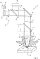
- FIG. 1 shows a laser processing device 1, which is used in particular for laser cutting or welding of metal workpieces, such as metal sheets.
- the laser processing device 1 is part of a laser processing system which comprises, for example, a CO 2 laser or a solid-state laser for generating a laser beam 2 .
- the laser beam 2 is supplied to the laser processing device 1 by means of a beam guide not shown.
- a nozzle channel 5 of a laser machining nozzle 6 When passing through the nozzle channel 5 of the laser beam 2 runs along a laser beam axis 9.
- the nozzle 6 is on attached to a nozzle receptacle, which is not shown for clarity in the figures.
- more details of the processing device 1, such. B. a supply of process gases, which can be fed via the nozzle to the process area 7, are not shown for clarity in the figures.
- the position of the process area 7 on the workpiece 8 can be varied by a relative movement by means of movement devices, likewise not shown, between the laser steel 2 and the workpiece 8.
- the laser processing device 1 has a detection device 10 for detecting radiation, which is reflected or emitted by the process area 7.
- the radiation of the process area 7 can be detected in a detection direction through the nozzle 6.
- the detection direction runs in the region of the nozzle 6 parallel to the laser beam axis 9 and in FIG. 1 from top down.
- the radiation of the process area 7 is consequently decoupled coaxially.
- the course of the detected radiation is in FIG. 1 represented by solid lines 11 .
- the decoupling via the partially transparent deflecting mirror 3, which z. B. for radiation in a wavelength range 500 to 2000 nm is transparent, but the laser light (CO 2 : 10.6 microns, solid: eg., 1.03 microns) reflected.
- a decoupling can also be done with the help of a scraper, Riefen- or perforated mirror.
- a further deflecting mirror 12 In order to convey the decoupled radiation to an optical detector of the detection device 10, a further deflecting mirror 12, a partially transparent deflecting mirror 13 and a lens 14 are provided.
- an optical detector or optical sensor is a spatially resolving Nahinfrarot camera 15, which z. B. based on silicon as a semiconductor material and is operated with an upstream bandpass filter in the near-infrared spectral range.
- an evaluation unit 16 is provided for evaluation of the camera recordings.
- another optical sensor can be used, which z. B. provides integrated intensity values over the detected area.
- the inner surface of the nozzle 6 or the nozzle channel wall has, starting from a process-remote nozzle opening 20, a conical section 21 .
- a short cylindrical section 22 extends between the conical section 21 and the process-facing nozzle opening 23.
- FIG. 1 It can be seen that at least part of the inner surface of the nozzle 6 or the nozzle channel wall, starting from the process-facing nozzle opening 20, in particular in the viewing direction parallel to the course of the nozzle channel 5, ie in the detection direction, is visible.
- the conical section 21 and the cylindrical section 22 of the nozzle channel wall form a contrast section 25.
- It is provided with a coating which, compared to the uncoated surface of the base body 24 of the nozzle 6 for radiation has an absorbing effect at least at the observation wavelength. Thanks to the absorbent coating, radiation is at least significantly prevented at least at the observation wavelength, which, starting from the process area 7, directly hits the contrast section 25 , is reflected there. For the reflected radiation would reach the camera 15 via the focusing lens 4, etc., and adversely affect the signal quality of the process images.
- the entire outer surface of the nozzle 6 has no coating.
- the nozzle 6 is well suited for use with a capacitive distance sensor, not shown.
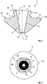
- the nozzle 6 is in FIG. 1 slightly distorted. In detail, the nozzle 6 is therefore further based on the FIGS. 2 to 3 which show true-to-scale illustrations of the nozzle 6.
- the nozzle 6 has a metallic base body 24 made of copper.
- the nozzle channel 5, which is guided centrally through the main body 24, is designed to be rotationally symmetrical about the laser beam axis 9.
- an external thread 35 is provided, by means of which the nozzle 6 can be replaceably fastened to the nozzle receptacle, not shown, of the processing device 1.
- an outer edge 26 of the nozzle 6 is polygonal-shaped to provide an opportunity to attack a tool for loosening or tightening the nozzle 6 to the nozzle holder.
- the nozzle openings 20, 23 and the entire nozzle channel 5 have circular cross-sections.
- the process-remote nozzle opening 20 has, for example, a diameter of 7 to 10 mm, while the process-facing nozzle opening 23, for example, has a diameter of 0.7 to 3.0 mm.
- the conical section 21 extends at an angle of inclination of approximately 11 ° with respect to the course of the nozzle channel 5.
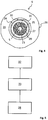
- the nozzle 6 is shown in a plan view parallel to the course of the nozzle channel 5 on the process-facing nozzle opening 20. From this viewing direction, which corresponds to the detection direction of the detection device 10, the contrast section 25 completely surrounds the process-facing nozzle opening 23. By a dashed circle 27 , the area recorded by the camera 15 is indicated. In this receiving region 27, the contrast section 25 forms the edge region immediately adjacent to the nozzle opening 20.
- nozzle 6 which has an absorbent coating at least almost on the entire nozzle channel wall. The remaining surface of the nozzle 6, however, has no coating.
- the contrast section 25 is preferably provided with radiation at the observation wavelength absorbing coating which is not or only in the case of radiation having a wavelength greater than 2000 nm is absorbent to a small extent.
- FIG. 4 a second nozzle 6 is shown extending from the in the FIGS. 1 to 3 only differs in that the nozzle channel wall formed as a contrast section 25 instead of an absorbent coating has a surface structure which achieves a scattering effect at least for the observation wavelength.
- the nozzle 6 is according to FIG. 4 identical to the nozzle 6 according to the FIGS. 1 to 3 built up.
- Steps of a method for starting up a nozzle 6 are listed on the laser processing device 1.
- the nozzle 6 is attached to the nozzle holder of the laser processing device 1.
- it is checked by means of the detection device 10 whether the inner surface of the nozzle 6 has an expected contrast section 25.
- a process monitoring using the detection device 10 for the subsequent laser processing using the checked nozzle 6 is activated or not deactivated. Otherwise, process monitoring is deactivated or not activated.
- the evaluation unit 16 has an in FIG. 1 indicated activation / deactivation unit 17 .
- the monitoring of the process area 7 takes place at an observation wavelength between, for example, 300 and 1100 nm.
- the laser processing device 1 can comprise a detection device 10 for monitoring at another observation wavelength between, for example, 900 and 1700 nm. Consequently, the contrast section 25 of the nozzle 6 advantageously has an absorbing effect, in particular by an absorbing coating, for radiation at least at the respective observation wavelengths.
- the laser processing device 1 can also have an illumination device 18 , by means of which at least the process region 7 can be illuminated.
- an illumination device 18 is indicated, by means of which the process area 7 can be illuminated through the nozzle 6.
- the course of the illumination light is in FIG. 1 indicated by dashed lines 19 . So that the signal quality of the detection device 10 is increased due to the illumination, the illumination with radiation should take place at least at a wavelength which corresponds to the observation wavelength of the detection device 10.
Description
Die Erfindung betrifft eine Laserbearbeitungsdüse für eine Laserbearbeitungseinrichtung, wobei die Laserbearbeitungseinrichtung zur Prozessüberwachung eine Detektionseinrichtung zur Detektion von Strahlung eines durch die Laserbearbeitungsdüse definierten Prozessbereichs aufweist. Des Weiteren betrifft die Erfindung eine Laserbearbeitungseinrichtung mit einer solchen Laserbearbeitungsdüse sowie ein Verfahren zur Inbetriebnahme einer solchen Laserbearbeitungsdüse an der Laserbearbeitungseinrichtung.The invention relates to a laser processing nozzle for a laser processing device, wherein the laser processing device for process monitoring has a detection device for detecting radiation of a process region defined by the laser processing nozzle. Furthermore, the invention relates to a laser processing device with such a laser processing nozzle and to a method for starting up such a laser processing nozzle on the laser processing device.
Trotz enormer Fortschritte bei der Steuerung von Laserbearbeitungsprozessen, kann es auch auf modernen Laserbearbeitungsanlagen immer wieder zu fehlerhaften Bearbeitungsergebnissen kommen. Um Fehlprozesse bereits während der Bearbeitung erkennen und eventuelle Abhilfemaßnahmen treffen zu können, ist es bekannt, den Prozessbereich optisch zu überwachen.Despite enormous progress in the control of laser processing processes, it can also lead to erroneous processing results on modern laser processing systems again and again. In order to be able to recognize incorrect processes already during processing and to be able to take possible corrective measures, it is known to optically monitor the process area.
Je nachdem, wie die optischen Sensoren angeordnet sind, wird zwischen einer off-axis, quasi-koaxialen und koaxialen Auskopplung der Prozessstrahlung unterschieden. Im Fall der off-axis Auskopplung wird die Strahlung des Bearbeitungsprozesses aus einer Detektionsrichtung beobachtet, welche in einem Winkel von größer als 10° zur Laserstrahlachse verläuft. Bei einer quasi-koaxialen Auskopplung verläuft die Detektionsrichtung in einem Winkel von kleiner als 10° zur Laserstrahlachse. Von einer koaxialen Auskopplung wird gesprochen, wenn die Detektionsrichtung parallel zur Laserstrahlachse verläuft. Insbesondere für die letzte Variante hat sich eine Detektion des Prozesslichtes durch die Laserbearbeitungsdüse hindurch bewährt, da aus dieser Richtung der Prozessbereich besonders ungehindert eingesehen werden kann.Depending on how the optical sensors are arranged, a distinction is made between an off-axis, quasi-coaxial and coaxial extraction of the process radiation. In the case of off-axis decoupling, the radiation of the machining process is observed from a detection direction which extends at an angle of greater than 10 ° to the laser beam axis. In a quasi-coaxial Outcoupling, the detection direction is at an angle of less than 10 ° to the laser beam axis. From a coaxial coupling is spoken when the detection direction is parallel to the laser beam axis. In particular for the last variant, a detection of the process light through the laser processing nozzle has proven itself, since the process region can be viewed particularly freely from this direction.
Ein Beispiel für eine Detektionseinrichtung an einer CO2-Laserschneidanlage, bei welcher eine Detektion des Prozesslichtes durch eine Laserbearbeitungsdüse hindurch erfolgt, wird durch die
Aus der
Durch die
Ausgehend vom Stand der Technik hat sich die Erfindung zur Aufgabe gesetzt, die Signalqualität der detektierten Strahlung des Prozessbereichs bei zumindest einer Beobachtungs-Wellenlänge zu verbessern.Based on the prior art, the invention has set itself the task, the signal quality of the detected radiation of the process area at least one To improve observation wavelength.
Gelöst wird die Aufgabe durch eine Laserbearbeitungsdüse mit den Merkmalen von Anspruch 1.The object is achieved by a laser processing nozzle having the features of
Erfindungsgemäß weist die Oberfläche der Laserbearbeitungsdüse zumindest einen Kontrastabschnitt auf, welcher zumindest für Strahlung bzw. Licht bei einer zur Prozessüberwachung durch eine Detektionseinrichtung geeigneten Beobachtungs-Wellenlänge eine streuende und/oder absorbierende Wirkung aufweist. Eine geeignete Beobachtungs-Wellenlänge ist eine Wellenlänge, bei welcher eine Überwachung eines Laserbearbeitungsprozesses mittels einer Detektionseinrichtung Rückschlüsse auf den Bearbeitungsprozess zulässt. Insbesondere liegt daher eine mögliche Beobachtungs-Wellenlänge im Bereich zwischen 300 bis 3000 nm, welcher sowohl den sichtbaren als auch den nahinfraroten Spektralbereich umfasst.According to the invention, the surface of the laser processing nozzle has at least one contrast section which has a scattering and / or absorbing effect at least for radiation or light at an observation wavelength suitable for process monitoring by a detection device. A suitable observation wavelength is a wavelength at which monitoring of a laser processing process by means of a detection device allows conclusions to be drawn about the processing process. In particular, therefore, a possible observation wavelength in the range between 300 to 3000 nm, which includes both the visible and the near-infrared spectral range.
Die Laserbearbeitungsdüse weist einen metallischen Grundkörper auf, auf dessen Oberfläche zumindest im Kontrastabschnitt eine für Strahlung zumindest bei einer Beobachtungs-Wellenlänge zwischen 300 und 1100 nm und/oder für Strahlung zumindest bei einer Beobachtungs-Wellenlänge zwischen 900 und 1700 nm absorbierende Beschichtung aufgebracht und/oder eine streuende Oberflächenstruktur gebildet ist.The laser processing nozzle has a metallic base body, on the surface of which, at least in the contrast section, a coating absorbing at least at an observation wavelength between 300 and 1100 nm and / or for radiation at least at an observation wavelength between 900 and 1700 nm is applied and / or a scattering surface structure is formed.
Ein metallischer Grundkörper, insbesondere aus Kupfer, weist eine gute Widerstandsfähigkeit gegen die thermischen und mechanischen Beanspruchungen während der Laserbearbeitung auf. Zudem eignet sich eine Düse mit metallischem Grundkörper für den Einsatz zusammen mit weiterer Sensorik von Laserbearbeitungseinrichtungen, wie beispielsweise einer kapazitiven Abstandssensorik. Insbesondere weist eine absorbierende Beschichtung des Kontrastabschnitts zumindest bei der Beobachtungs-Wellenlänge einen höheren Absorptionsgrad auf als die unbeschichtete Materialoberfläche des metallischen Grundkörpers.A metallic base body, in particular of copper, has a good resistance to the thermal and mechanical stresses during laser processing. In addition, a nozzle with a metallic base body is suitable for use together with other sensors of laser processing equipment, such as a capacitive distance sensor. In particular, an absorbing coating of the contrast section, at least at the observation wavelength, has a higher degree of absorption than the uncoated material surface of the metallic base body.
Vorzugsweise erfolgt eine Detektion des Prozesseigenleuchtens bei einer Wellenlänge zwischen 300 und 1100 nm, da für diesen Wellenlängenbereich gut geeignete Silicium-basierte Detektoren zur Verfügung stehen. Ebenfalls bevorzugt erfolgt die Detektion einer Wellenlänge zwischen 900 bis 1700 nm. Für diesen Wellenlängenbereich sind z. B. InGaAs-basierte Detektoren gut geeignet..Preferably, the process lighting is detected in a process Wavelength between 300 and 1100 nm, as well-suited for this wavelength range silicon-based detectors are available. Likewise preferably, the detection of a wavelength between 900 to 1700 nm. For this wavelength range z. B. InGaAs-based detectors well suited ..
Es versteht sich, dass ein optischer Detektor, Sensor bzw. eine Bilderfassungseinrichtung der Detektionseinrichtung nicht nur Strahlung bei genau einer Wellenlänge detektiert. Vielmehr wird- je nach Art des Detektors und eventuell vorgeschalteter Filter - i. d. R. ein schmaler Wellenlängenbereich um eine Beobachtungs-Wellenlänge detektiert.It is understood that an optical detector, sensor or an image detection device of the detection device not only detects radiation at exactly one wavelength. Rather, depending on the type of detector and possibly upstream filter - i. d. R. detects a narrow wavelength range around an observation wavelength.
Jedenfalls sorgt sowohl eine streuende als auch eine absorbierende Wirkung auf die von dem Prozessbereich ausgehende Strahlung bei einer Beobachtungs-Wellenlänge dafür, dass die Strahlung, welche an dem Kontrastabschnitt auf die Düse auftritt, in wesentlich geringerem Umfang zur Detektionseinrichtung hin reflektiert werden kann. Ein Auftreten von störenden Reflexen wird reduziert. Aufgrund der erfindungsgemäßen optischen Eigenschaften des Kontrastabschnittes ist in den Aufnahmen der Detektionseinrichtung die Abbildung des Kontrastabschnittes sehr gut von der Abbildung des Prozessbereichs zu unterscheiden.In any case, both a scattering and an absorbing effect on the radiation emanating from the process area at an observation wavelength ensures that the radiation which occurs at the contrast section on the nozzle can be reflected to the detection device to a much lesser extent. An occurrence of disturbing reflections is reduced. Due to the optical properties of the contrast section according to the invention, the image of the contrast section can be distinguished very well from the image of the process area in the images of the detection device.
Die streuende Wirkung des Kontrastabschnittes kann beispielsweise durch eine Oberflächenstrukturierung erzielt werden. Anstelle einer glatten metallischen Oberfläche weist die Oberfläche der Düse zumindest im Bereich des Kontrastabschnittes eine derartige Rauigkeit auf, dass die Strahlung bei der Beobachtungs-Wellenlänge gestreut wird. Vorteilhafterweise kann eine solche Oberflächenstrukturierung relativ kostengünstig hergestellt werden. Vorzugsweise entspricht das Maß der Rauigkeit zumindest in etwa der Größenordnung der Beobachtungs-Wellenlänge.The scattering effect of the contrast section can be achieved for example by surface structuring. Instead of a smooth metallic one Surface, the surface of the nozzle, at least in the region of the contrast section on such roughness, that the radiation is scattered at the observation wavelength. Advantageously, such a surface structuring can be produced relatively inexpensively. The degree of roughness preferably corresponds at least approximately to the magnitude of the observation wavelength.
Eine absorbierende Wirkung im Sinne der Erfindung ergibt sich insbesondere, wenn der Absorptionsgrad für Strahlung zumindest bei der Beobachtungs-Wellenlänge größer als 0.3 ist. Vorzugsweise liegt der Absorptionsgrad für Strahlung bei zumindest der Beobachtungs-Wellenlänge bei einem Wert größer als 0.5, noch vorteilhafter ist der Absorptionsgrad für Strahlung der Beobachtungs-Wellenlänge größer als 0.7 oder sogar größer als 0.9. Das Entstehen von störenden Reflexen an dem Kontrastabschnitt wird auf diese Weise wirkungsvoll unterbunden.An absorbing effect in the context of the invention results in particular if the absorption coefficient for radiation is greater than 0.3 at least at the observation wavelength. The absorption coefficient for radiation is preferably greater than 0.5 at at least the observation wavelength, more advantageously the absorption coefficient for radiation of the observation wavelength is greater than 0.7 or even greater than 0.9. The emergence of disturbing reflections at the contrast section is effectively prevented in this way.
Vorzugsweise weist der Kontrastabschnitt zumindest bei der Beobachtungs-Wellenlänge einen Reflexionsgrad auf, der sich von dem Reflexionsgrad der Oberfläche des Werkstückes, die ebenfalls durch die Detektionseinrichtung erfasst wird, unterscheidet, vorzugsweise kleiner ist. Insbesondere beträgt der Reflexionsgradunterschied einen Wert von mindestens 0.1, vorzugsweise mindestens 0.3 oder sogar mindestens 0.5,. Dank dieser Maßnahme ergibt sich in der Aufnahme der Detektionseinrichtung ein hoher Kontrast zwischen dem abgebildeten Teil der Düse und der abgebildeten Werkstückoberfläche. Bei einer Detektion durch die Düse hindurch, kann somit z. B. der Durchmesser der prozesszugewandten Düsenöffnung zuverlässig überprüft bzw. sehr genau vermessen werden.Preferably, the contrasting portion, at least at the observation wavelength, has a reflectance that is different from, preferably smaller, the reflectance of the surface of the workpiece that is also detected by the detection device. In particular, the reflectance difference is a value of at least 0.1, preferably at least 0.3 or even at least 0.5. Thanks to this measure, the recording of the detection device results in a high contrast between the imaged part of the nozzle and the imaged workpiece surface. Upon detection through the nozzle, z. B. the diameter of the process-facing nozzle opening reliably checked or measured very accurately.
Sehr häufig werden Laserbearbeitungseinrichtungen zur Bearbeitung von z. B. Bau- und/oder Edelstahl eingesetzt. Daher weist im Speziellen der Kontrastabschnitt der Düse für Strahlung bei der Beobachtungs-Wellenlänge einen Reflexionsgrad auf, der sich von dem Reflexionsgrad der Oberfläche von Baustahl und/oder Edelstahl um mindestens 0.1, vorzugsweise mindestens 0.3 oder sogar mindestens 0.5 unterscheidet, insbesondere um diese Werte kleiner ist als dieser.Very often laser processing equipment for processing z. B. construction and / or stainless steel used. Therefore, in particular, the contrast portion of the nozzle for radiation at the observation wavelength has a reflectance which differs from the reflectance of the surface of structural steel and / or stainless steel by at least 0.1, preferably at least 0.3 or even at least 0.5, in particular smaller by these values is as this.
Der Kontrastabschnitt der Düse ist vorzugsweise derart ausgebildet, dass im Vergleich zu einer Düse ohne Kontrastabschnitt ein geringerer Anteil der Strahlung zumindest bei der Beobachtungswellenlänge durch Reflexion an der Düsenoberfläche zur Detektionseinrichtung gelangen kann. Insbesondere wird dies durch einen Reflexionsgrad des Kontrastabschnitts gemäß den vorstehenden Angaben bezogen auf den Erfassungsbereich der Detektionseinrichtung erreicht.The contrast section of the nozzle is preferably designed such that, compared to a nozzle without a contrast section, a smaller proportion of the radiation can reach the detection device by reflection at the nozzle surface at least at the observation wavelength. In particular, this is achieved by a reflectance of the contrast section according to the above statements with respect to the detection range of the detection device.
Besonders wirkungsvoll wird die Signalqualität der von dem Prozessbereich ausgehenden und von einer Detektionseinrichtung detektierten Strahlung im Fall eines bevorzugten Ausführungsbeispiels verbessert, indem der Kontrastabschnitt auf der Düsenoberfläche derart angeordnet ist, dass Strahlung von dem Prozessbereich direkt auf den Kontrastabschnitt auftreffen kann.The signal quality of the radiation emanating from the process area and detected by a detection device is particularly effectively improved in the case of a preferred embodiment in that the contrast section is arranged on the nozzle surface in such a way that radiation from the process area can impinge directly on the contrast section.
Alternativ oder ergänzend ist der Kontrastabschnitt vorzugsweise derart auf der Düsenoberfläche angeordnet, dass der Kontrastabschnitt im Detektions- bzw. Aufnahmebereich einer Detektionseinrichtung zur Detektion von Strahlung eines durch die Laserdüse definierten Prozessbereichs angeordnet werden kann. Dies ist insbesondere dann von Vorteil, wenn die Detektionseinrichtung nicht oder nicht nur zur direkten Betrachtung des unmittelbaren Laserbearbeitungsprozesses sondern (auch) insofern zur Prozessüberwachung dient, dass mittels der Detektionseinrichtung z. B. der Zustand bzw. die Abmessungen der Düse überprüft werden können. Aufgrund des im Aufnahmebereich der Detektionseinrichtung angeordneten Kontrastabschnitts kann folglich eine Vermessung oder Überprüfung des abgebildeten Teils der montierten Düse durch die Detektionseinrichtung während der Laserbearbeitung mit einer höheren Genauigkeit und Zuverlässigkeit erfolgen.Alternatively or additionally, the contrast section is preferably arranged on the nozzle surface such that the contrast section can be arranged in the detection or recording area of a detection device for detecting radiation of a process area defined by the laser nozzle. This is particularly advantageous when the detection device is not or not only for direct viewing of the immediate laser processing process but (also) insofar as for process monitoring that by means of the detection device z. B. the state or the dimensions of the nozzle can be checked. Consequently, due to the contrast section arranged in the receiving area of the detection device, a measurement or checking of the imaged part of the mounted nozzle by the detection device during the laser processing can be carried out with a higher accuracy and reliability.
Dies trifft im Speziellen für eine Anordnung des Kontrastabschnittes zu, bei welcher die Strahlung, welche von dem durch die Laserdüse definierten Prozessbereich kommt, direkt auf den Kontrastabschnitt auftreffen kann und durch einmalige Reflexion an dem Kontrastabschnitt zu einer Detektionseinrichtung gelangen kann bzw. könnte, sofern sie nicht an dem Kontrastabschnitt absorbiert bzw. gestreut wird.This is especially true for an arrangement of the contrast section, in which the radiation coming from the process area defined by the laser nozzle can impinge directly on the contrast section and, by a single reflection at the contrast section, could or could reach a detection device, if they are is not absorbed or scattered at the contrast portion.
Beispielsweise ist bei einer Düse für eine Laserbearbeitungseinrichtung mit einer seitlichen Detektionseinrichtung (off-axis Auskopplung) der Kontrastabschnitt an der Düsenaußenfläche zumindest an derjenigen Seite angeordnet, welche der Detektionseinrichtung zugewandt ist.For example, in the case of a nozzle for a laser processing device with a lateral detection device (off-axis decoupling), the contrast section is arranged on the nozzle outer surface at least on that side which faces the detection device.
Durch die Düse können der Laserstrahl und zusätzlich Prozessgase zum Prozessbereich geführt werden. Zu diesem Zweck weist sie einen Düsenkanal auf, welcher zwischen zwei Düsenöffnungen verläuft. Eine Düsenöffnung ist dem Prozessbereich zugewandt, eine Düsenöffnung ist dem Prozessbereich abgewandt.Through the nozzle, the laser beam and additional process gases can be guided to the process area. For this purpose, it has a nozzle channel which extends between two nozzle openings. A nozzle opening faces the process area, and a nozzle opening faces away from the process area.
Bei einem besonders bevorzugten Ausführungsbeispiel ist die Düse derart ausgebildet, dass die Strahlung des Prozessbereichs mittels der Detektionseinrichtung durch den zwischen zwei Düsenöffnungen verlaufenden Düsenkanal hindurch detektierbar ist. Die Düse ist folglich für den Einsatz auf einer Laserbearbeitungseinrichtung mit koaxialer bzw. quasi-koaxialer Auskopplung des zu detektierenden Prozesslichtes geeignet. Vorzugsweise ist der Kontrastabschnitt in diesem Fall derart an der Düsenkanalwandung angeordnet, dass er ausgehend von derjenigen Düsenöffnung, welche im Betrieb dem Prozessbereich abgewandt ist, sichtbar ist. Die Düse ist folglich derart aufgebaut, dass Strahlung, die an dem Kontrastabschnitt emittiert bzw. reflektiert wird, entgegen der Detektionsrichtung (bei koaxialer Auskopplung parallel zur Laserstrahlachse bzw. zum Verlauf des Düsenkanals) durch die prozessabgewandte Düsenöffnung aus der Düse austreten kann und damit zur Detektionseinrichtung gelangen könnte. Dies ergibt sich insbesondere, wenn der Kontrastabschnitt in einem Neigungswinkel zwischen 0° und 90° gegenüber dem Verlauf des Düsenkanals bzw. der Laserstrahlachse oder der Detektionsrichtung, vorzugsweise in einem Neigungswinkel zwischen 0° und 45°, weiter vorzugsweise in einem Neigungswinkel von 5° bis 15° verläuft.In a particularly preferred embodiment, the nozzle is designed such that the radiation of the process area can be detected by means of the detection device through the nozzle channel extending between two nozzle openings. The nozzle is therefore suitable for use on a laser processing device with coaxial or quasi-coaxial extraction of the process light to be detected. In this case, the contrast section is preferably arranged on the nozzle channel wall such that it is visible starting from the nozzle opening which faces away from the process area during operation. The nozzle is consequently constructed in such a way that radiation emitted or reflected at the contrast section can escape from the nozzle through the process-facing nozzle opening, contrary to the detection direction (in the case of coaxial decoupling parallel to the laser beam axis or to the course of the nozzle channel) and thus to the detection device could arrive. This results in particular when the contrast section at an angle of inclination between 0 ° and 90 ° with respect to the course of the nozzle channel or the laser beam axis or the detection direction, preferably at an inclination angle between 0 ° and 45 °, more preferably at an inclination angle of 5 ° 15 ° runs.
Im Speziellen ist die prozessabgewandte Düsenöffnung größer als die Öffnungsweite der Düseninnenfläche im Bereich des Kontrastabschnittes und sind zwischen der prozessabgewandten Düsenöffnung und dem Kontrastabschnitt auch keine weiteren Verengungen vorhanden, die den Blick in Detektionsrichtung auf den Kontrastabschnitt versperren. Dank dieser Maßnahme ist der Kontrastabschnitt für eine koaxiale Detektionseinrichtung sichtbar und erhöht aufgrund seines Kontrastes gegenüber dem Prozessbereich z. B. die Auswertbarkeit der Aufnahme der Detektionseinrichtung.In particular, the nozzle opening facing away from the process is larger than the opening width of the nozzle inner surface in the region of the contrast section, and no further constrictions are present between the nozzle opening facing away from the process and the contrast section, blocking the view in the detection direction on the contrast section. Thanks to this measure, the contrast section for a coaxial detection device is visible and increases due to its contrast opposite the process area z. B. the readability of the recording of the detection device.
Im Falle eines besonders bevorzugten Ausführungsbeispiels der Erfindung weist der Kontrastabschnitt mittels einer Beschichtung eine absorbierende Wirkung für Strahlung zumindest bei der Beobachtungs-Wellenlänge auf. Die Beschichtung kann speziell für die gewünschte absorbierende Wirkung gewählt werden, wobei die Düse darüber hinaus aus einem oder mehreren anderen Materialien aufgebaut sein kann, die weitere Anforderungen an die Düse, wie Temperaturbeständigkeit usw., erfüllen.In the case of a particularly preferred embodiment of the invention, the contrast section by means of a coating has an absorbing effect for radiation at least at the observation wavelength. The coating may be selected specifically for the desired absorbing effect, and the nozzle may be further constructed of one or more other materials that meet other nozzle requirements such as temperature resistance, etc.
Die absorbierende Beschichtung ist vorzugsweise als glatte Beschichtung ausgebildet, was den Vorteil mit sich bringt, dass der Kontrastabschnitt aufgrund seiner glatten Oberfläche keine störenden Einflüsse auf die Gasströmung durch die Düse hindurch besitzt.The absorbent coating is preferably formed as a smooth coating, which has the advantage that the contrast section has no disturbing influences on the gas flow through the nozzle due to its smooth surface.
Bei einer vorteilhaften Weiterentwicklung der Erfindung weist zumindest ein im Betrieb dem Prozessbereich zugewandter Teil der Außenfläche der Düse keine Beschichtung wie der Kontrastabschnitt auf. Zum einen ist der während der Bearbeitung dem Werkstück zugewandte Teil der Düsenaußenfläche in besonderem Maße Emissionen ausgesetzt. Sowohl die thermische als auch die mechanische Beanspruchung z. B. durch Spritzer sind dort besonders hoch. Falls an diesem Teil der Düse ebenfalls eine absorbierende Beschichtung aufgebracht wäre, müsste diese zusätzlich zur absorbierenden Wirkung auch noch eine besonders hohe Widerstand kraft gegen thermische und mechanische Beanspruchungen aufweisen. Dies erschwert die Auswahl einer geeigneten Beschichtung. Zum anderen wird häufig der Abstand zwischen der Düse und einem Werkstück durch Kapazitätsmessungen zwischen der Düse und dem Werkstück ermittelt. Eine Beschichtung der Düsenaußenfläche kann unerwünschte Effekte auf die Kapazitätsmessungen haben. Insbesondere ist es vor diesem Hintergrund vorteilhaft, wenn die gesamte Außenfläche der Düse keine Beschichtung entsprechend des Kontrastabschnitts aufweist.In an advantageous further development of the invention, at least one part of the outer surface of the nozzle facing the process area during operation does not have a coating like the contrast section. On the one hand, the part of the nozzle outer surface which faces the workpiece during machining is exposed to particular emissions. Both the thermal and the mechanical stress z. B. by splashes are particularly high there. If an absorbent coating would also be applied to this part of the nozzle, this would have in addition to the absorbing effect also a particularly high resistance force against thermal and mechanical stresses. This makes it difficult to choose a suitable coating. On the other hand, the distance between the nozzle and a workpiece is often determined by capacitance measurements between the nozzle and the workpiece. A coating of the nozzle outer surface may have undesirable effects on the capacitance measurements. In particular, it is advantageous against this background if the entire outer surface of the nozzle does not have a coating corresponding to the contrast section.
Die Wahl der Wellenlänge, bei welcher eine Detektionseinrichtung den Prozessbereich beobachtet, ist von verschiedenen Aspekten abhängig. Beispielsweise ist maßgeblich, welche Fehlprozesse vor allem festgestellt werden sollen. Generell kann an ein und derselben Laserbearbeitungseinrichtung aber auch Strahlung des Prozessbereichs bei verschiedenen Wellenlängen detektiert werden. Zu diesem Zweck können auch mehrere separate Detektionseinrichtungen vorhanden sein.
Zum einen kann Strahlung detektiert werden, die lediglich an dem Prozessbereich reflektiert wird. Zum anderen kann Strahlung detektiert werden, die im Prozessbereich aufgrund des Laserbearbeitungsprozesses entsteht und emittiert wird. Das emittierte Prozesslicht, das sogenannte Prozesseigenleuchten, ist besonders geeignet, Feststellungen über eventuelle Prozessfehlentwicklungen im Prozessbereich zu treffen.The choice of the wavelength at which a detection device the Process area is dependent on various aspects. For example, it is decisive which faulty processes are to be determined first and foremost. In general, radiation of the process area at different wavelengths can also be detected at one and the same laser processing device. For this purpose, several separate detection devices may be present.
On the one hand, radiation can be detected, which is only reflected at the process area. On the other hand, radiation can be detected which is produced and emitted in the process area due to the laser processing process. The emitted process light, the so-called process lighting, is particularly suitable for making determinations about possible process failures in the process area.
Durch die absorbierende Wirkung des Kontrastabschnittes wird demnach das Auftreten von störenden Reflexen von emittierter Prozessstrahlung reduziert, die sich besonders gut für eine Prozessüberwachung eignet.
Bei einer bevorzugten Variante ist der Kontrastabschnitt für Strahlung bei einer Beobachtungs-Wellenlänge absorbierend, wohingegen der Kontrastabschnitt Strahlung mit einer Wellenlänge von größer als 2000 nm nicht bzw. nur in einem geringen Umfang absorbiert.
Alternativ oder ergänzend werden störende Einflüsse des Laserstrahls der Laserbearbeitungseinrichtung, für welche die Laserdüse vorgesehen ist, auf die Laserdüse reduziert, wenn der Kontrastabschnitt bei der Wellenlänge des Laserstrahls nicht oder nur in geringem Umfang absorbierend wirkt. Im Speziellen ist der Kontrastabschnitt folglich für Strahlung bei einer Wellenlänge von etwa 10,6 µm und/oder etwa 1,03 µm nicht oder nur in geringem Umfang absorbierend.The absorbing effect of the contrast section therefore reduces the occurrence of disturbing reflections of emitted process radiation, which is particularly well suited for process monitoring.
In a preferred variant, the contrast section for radiation at an observation wavelength is absorbent, whereas the contrast section does not absorb radiation with a wavelength of greater than 2000 nm or only to a small extent.
Alternatively or additionally, interfering influences of the laser beam of the laser processing device for which the laser nozzle is provided are reduced to the laser nozzle when the contrast section at the wavelength of the Laser beam does not or only to a small extent absorbs. In particular, the contrast portion is therefore not or only slightly absorbable for radiation at a wavelength of about 10.6 μm and / or about 1.03 μm.
Eine absorbierende Wirkung in geringem Umfang liegt dann vor, wenn der Kontrastabschnitt einen Absorptionsgrad von kleiner als 0.5, insbesondere von kleiner als 0.3, aufweist. Keine absorbierende Wirkung liegt insbesondere vor, wenn der Absorptionsgrad der Oberfläche kleiner als 0.1 ist. Dank dieser Maßnahme reflektiert der Kontrastabschnitt einen erheblichen Teil des Laserstrahls oder der Wärmestrahlung des Prozessbereichs, welcher nicht zur Prozessüberwachung benötigt wird. Einem übermäßigen Aufheizen der Düse wird entgegengewirkt.An absorbing effect to a lesser extent is present when the contrast section has an absorption factor of less than 0.5, in particular less than 0.3. No absorbing effect is present, in particular, when the absorption coefficient of the surface is less than 0.1. Thanks to this measure, the contrast section reflects a considerable part of the laser beam or the heat radiation of the process area, which is not needed for process monitoring. Excessive heating of the nozzle is counteracted.
Laserbearbeitungsdüsen stellen üblicherweise Verbrauchsteile dar. Sie müssen im Laufe der Lebensdauer einer Laserbearbeitungseinrichtung mehrfach ausgewechselt werden. Außerdem sind sie meistens speziell für die jeweiligen Bearbeitungsaufgaben gestaltet. Im Falle der erfindungsgemäßen Düse handelt es sich folglich vorteilhafterweise um eine auswechselbare Düse. Die Düse ist vorzugsweise einstückig, insbesondere, abgesehen von einer eventuellen absorbierenden Beschichtung, materialeinheitlich. Bei einer bevorzugten Ausführungsvariante ist die Düse ohne eine integrierte Wasserführung ausgebildet.Laser processing nozzles are usually consumables. They must be replaced several times over the life of a laser processing device. Moreover, they are usually designed especially for the respective processing tasks. Consequently, in the case of the nozzle according to the invention, it is advantageously a replaceable nozzle. The nozzle is preferably in one piece, in particular, apart from a possible absorbent coating, of the same material. In a preferred embodiment, the nozzle is formed without an integrated water supply.
Fertigungstechnisch vorteilhaft ist eine Ausgestaltung der Laserbearbeitungsdüse als im Wesentlichen rotationssymetrisches Bauteil. Eine kostengünstige Herstellung als Drehteil wird ermöglicht. Zur Befestigung an der Laserbearbeitungseinrichtung kann die Laserbearbeitungsdüse beispielsweise im Bereich der prozessabgewandten Düsenöffnung mit einem Außengewinde versehen sein.An embodiment of the laser processing nozzle as an essentially rotationally symmetrical component is advantageous in terms of manufacturing technology. An inexpensive production as a turned part is made possible. For attachment to the laser processing device, the laser processing nozzle can be provided, for example, in the region of the process-facing nozzle opening with an external thread.
Vorzugsweise ist der Kontrastabschnitt zumindest teilweise an einem konischen Abschnitt ihrer Innenfläche bzw. der Düsenkanalwandung angeordnet. Der Kontrastabschnitt kann somit zur Formung der Prozessgasströmung dienen und ist zugleich in Detektionsrichtung gut sichtbar. Im Speziellen verläuft er in einem Neigungswinkel zwischen 5° und 15° zum Verlauf des Düsenkanals bzw. der Laserstrahlachse oder Detektionsrichtung.Preferably, the contrast section is at least partially disposed on a conical portion of its inner surface or the nozzle channel wall. The contrast section can thus serve to shape the process gas flow and is also clearly visible in the detection direction. In particular, it runs at an angle of inclination between 5 ° and 15 ° to the course of the nozzle channel or the laser beam axis or detection direction.
Bei einer besonders bevorzugten Weiterentwicklung der Erfindung ist der Kontrastabschnitt derart angeordnet, dass durch die Düse hindurch gesehen der Kontrastabschnitt die Düsenöffnung umgibt, welche im Betrieb dem Prozessbereich zugewandt ist. Der Kontrastabschnitt kann folglich im Randbereich der sich in der Detektionseinrichtung ergebenden Abbildung des Prozessbereichs dargestellt werden und kann bei der Auswertung auf einfache Weise zur Vermessung der Düse dienen oder eventuell unberücksichtigt bleiben. Insbesondere ist es für eine möglichst vollständige Unterdrückung von störenden Reflexen vorteilhaft, wenn der Kontrastabschnitt die Düsenöffnung in Blickrichtung parallel zum Verlauf des Düsenkanals gesehen, vollständig umgibt.In a particularly preferred further development of the invention, the contrast section is arranged such that viewed through the nozzle the contrast section surrounds the nozzle opening, which faces the process area during operation. The contrast section can consequently be represented in the edge area of the image of the process area resulting in the detection device and can easily be used for the measurement of the nozzle during the evaluation or may possibly be disregarded. In particular, it is advantageous for the most complete possible suppression of disturbing reflections when the contrast section completely surrounds the nozzle opening in the viewing direction parallel to the course of the nozzle channel.
Alternativ oder ergänzend ergibt sich für eine Auswertung der Detektoraufnahmen eine vorteilhafte Anordnung, wenn der Kontrastabschnitt durch die Düse hindurch gesehen unmittelbar an die Düsenöffnung angrenzt. Beispielsweise kann der Durchmesser der Düsenöffnung aufgrund des erhöhten Kontrasts zwischen dem Kontrastabschnitt und der Düsenöffnung besonders genau und zuverlässig bestimmt werden.Alternatively or additionally, an advantageous arrangement results for an evaluation of the detector recordings when the contrast section viewed through the nozzle directly adjoins the nozzle opening. For example, the diameter of the nozzle opening can be determined particularly accurately and reliably due to the increased contrast between the contrast section and the nozzle opening.
In diesem Sinne ist es von Vorteil, wenn bei einer Weiterbildung der Erfindung der Kontrastabschnitt bei einer Bauform einer Düse, bei welcher die prozesszugewandte Düsenöffnung an einen zylindrischen Abschnitt des Düsenkanals angrenzt, zumindest auch an diesem zylindrischen Abschnitt angeordnet ist.In this sense, it is advantageous if, in a further development of the invention, the contrast section is arranged at least on this cylindrical section in the case of a design of a nozzle in which the process-facing nozzle opening adjoins a cylindrical section of the nozzle channel.
Gemäß einem weiteren Aspekt der Erfindung weist eine Laserbearbeitungseinrichtung eine Düse mit einem Kontrastabschnitt und eine Detektionseinrichtung zur Detektion von Strahlung eines durch die Düse definierten Prozessbereichs bei zumindest einer Beobachtungs-Wellenlänge auf, wobei der Kontrastbereich die Strahlung zumindest bei der Beobachtungs-Wellenlänge absorbiert und/oder streut. Vorzugsweise erfolgt durch die Detektionseinrichtung eine koaxial oder zumindest quasi-koaxiale Beobachtung des Prozessbereichs durch die Düse hindurch.According to a further aspect of the invention, a laser processing device has a nozzle with a contrast section and a detection device for detecting radiation of a process region defined by the nozzle at at least one observation wavelength, wherein the contrast region absorbs the radiation at least at the observation wavelength and / or scatters. The detection device preferably carries out a coaxial or at least quasi-coaxial observation of the process area through the nozzle.
Im Falle einer besonders bevorzugten Weiterentwicklung weist die Laserbearbeitungseinrichtung eine Beleuchtungsvorrichtung auf, mittels derer zumindest der durch die Düse definierte Prozessbereich beleuchtbar ist. Beispielsweise kann die Beleuchtungsvorrichtung den Prozessbereich seitlich beleuchten, also nicht parallel zur Laserstrahlachse. In diesem Fall ist es von besonderem Vorteil, wenn der Kontrastabschnitt der Düse streuend oder absorbierend für die Strahlung der Beleuchtungsvorrichtung bei zumindest einer Wellenlänge wirkt, welche zugleich einer Beobachtungs-Wellenlänge der Detektionseinrichtung entspricht. Damit werden insbesondere störende Licht- bzw. Strahlungsreflexe aufgrund der Beleuchtungsvorrichtung an der Oberfläche der Düse reduziert oder sogar gänzlich verhindert.In the case of a particularly preferred further development, the laser processing device has a lighting device by means of which at least the process area defined by the nozzle can be illuminated. For example, the illumination device can illuminate the process area laterally, ie not parallel to the laser beam axis. In this case, it is of particular advantage if the contrast section of the nozzle acts scattering or absorbing for the radiation of the illumination device at at least one wavelength, which at the same time corresponds to an observation wavelength of the detection device. This disturbing light or radiation reflections are reduced due to the lighting device on the surface of the nozzle or even completely prevented.
Vorzugsweise ist mittels der Beleuchtungsvorrichtung der Prozessbereich durch diePreferably, by means of the lighting device, the process area through the
Düse hindurch beleuchtbar, d. h. die Beleuchtung erfolgt koaxial oder zumindest quasi-koaxial. Eine direkte und ungehinderte Beleuchtung des Prozessbereichs ist gewährleistet. Auch bei der koaxialen bzw. quasi-koaxialen Anordnung der Beleuchtungsvorrichtung ist es von Vorteil, wenn der Kontrastabschnitt eine streuende oder/und absorbierende Wirkung auf Strahlung der Beleuchtungsvorrichtung bei einer Wellenlänge hat, welche zugleich einer Beobachtungs-Wellenlänge entspricht. Ein die Strahlung bei zumindest einer detektierten Wellenlänge der Beleuchtungseinrichtung absorbierender Kontrastabschnitt hat zur Folge, dass der beleuchtete Kontrastabschnitt dunkler erscheint und dadurch der Kontrast zum Prozessbereich erhöht wird. Dahingegen wirkt sich ein streuender Kontrastabschnitt derart aus, dass durch die zurückgeworfene Streustrahlung des beleuchteten Kontrastabschnitts, dieser heller erscheint und dadurch der Kontrast zum Prozessbereich erhöht wird.Nozzle can be illuminated through, d. H. the illumination is coaxial or at least quasi-coaxial. A direct and unhindered illumination of the process area is guaranteed. It is also advantageous in the coaxial or quasi-coaxial arrangement of the illumination device if the contrast section has a scattering and / or absorbing effect on radiation of the illumination device at a wavelength which at the same time corresponds to an observation wavelength. A contrast section absorbing the radiation at at least one detected wavelength of the illumination device has the consequence that the illuminated contrast section appears darker and thereby the contrast to the process area is increased. On the other hand, a scattering contrast section has the effect that due to the reflected radiation of the illuminated contrast section reflected back, it appears brighter and thereby the contrast to the process area is increased.
Die der Düse zugewandte Oberfläche des Werkstückes wird ebenfalls durch die Beleuchtungsvorrichtung beleuchtet und gelangt bei der Werkstückbearbeitung in den Aufnahmebereich der Detektionseinrichtung. Vorzugsweise weist der Kontrastabschnitt der Düse zumindest für Strahlung der Beleuchtungsvorrichtung bei einer Wellenlänge, welche zugleich einer Beobachtungs-Wellenlänge entspricht, einen Reflexionsgrad auf, der sich von dem Reflexionsgrad der Werkstückoberfläche unterscheidet, insbesondere kleiner ist als dieser. Beispielsweise weist der Reflexionsgradunterschied einen Wert von mindestens 0.1, vorzugsweise mindestens 0.3 oder sogar mindestens 0.5 auf.The nozzle-facing surface of the workpiece is also illuminated by the illumination device and arrives at the workpiece processing in the receiving area of the detection device. Preferably, the contrast section of the nozzle at least for radiation of the illumination device at a wavelength which also corresponds to an observation wavelength, a reflectance which differs from the reflectance of the workpiece surface, in particular is smaller than this. For example, the reflectance difference has a value of at least 0.1, preferably at least 0.3 or even at least 0.5.
Im Speziellen weist der Kontrastabschnitt für Strahlung der Beleuchtungsvorrichtung bei einer Wellenlänge, welche zugleich einer Beobachtungs-Wellenlänge entspricht, einen Reflexionsgrad auf, der sich von dem Reflexionsgrad der Oberfläche von Baustahl und/oder Edelstahl um mindestens 0.1, vorzugsweise um mindestens 0.3 oder sogar um mindestens 0.5 unterscheidet, insbesondere um diese Werte kleiner ist als dieser.Specifically, the contrasting portion for radiation of the illumination device at a wavelength which also corresponds to an observation wavelength has a reflectance which is at least 0.1, preferably at least 0.3 or even at least, of the reflectance of the surface of structural steel and / or stainless steel 0.5 differs, especially around these values is smaller than this.
Bei einer bevorzugten Ausführungsart der Laserbearbeitungseinrichtung ist eine Aktivierungs-/Deaktivierungseinheit vorgesehen, mittels derer eine Prozessüberwachung durch die Detektionseinrichtung aktivier- und deaktivierbar ist, je nachdem, ob eine eingebaute Düse einen erwarteten Kontrastabschnitt aufweist oder nicht. Auf diese Weise ist sichergestellt, dass die Prozessüberwachung nicht mit einer Düse erfolgt, die mangels Kontrastabschnitt keine ausreichende Qualität des Signals der Detektionseinrichtung gewährleisten kann.In a preferred embodiment of the laser processing device, an activation / deactivation unit is provided by means of which a process monitoring by the detection device can be activated and deactivated, depending after whether or not a built-in nozzle has an expected contrast portion. In this way, it is ensured that the process monitoring does not take place with a nozzle, which can not guarantee a sufficient quality of the signal of the detection device for lack of contrast section.
In diesem Sinne wird gemäß einem weiteren Aspekt der Erfindung bei einem Verfahren zur Inbetriebnahme einer Düse an einer Laserbearbeitungseinrichtung, nachdem die Düse an der Bearbeitungseinrichtung angebracht wird, mittels einer Detektionseinrichtung überprüft, ob die Oberfläche der Düse einen erwarteten Kontrastabschnitt aufweist, welcher in Detektionsrichtung für die Detektionseinrichtung sichtbar ist und zumindest für Strahlung bei einer Beobachtungs-Wellenlänge der Detektionseinrichtung eine streuende und/oder absorbierende Wirkung aufweist. Vorzugsweise wird für den Fall, dass die Überprüfung der Düse ergibt, dass die Düse keinen Kontrastabschnitt aufweist, eine Prozessüberwachung durch die Detektionseinrichtung für die nachfolgende Laserbearbeitung unter Verwendung der Düse deaktiviert bzw. erst gar nicht aktiviert.In this sense, according to a further aspect of the invention, in a method for starting up a nozzle on a laser processing device, after the nozzle is attached to the processing device, it is checked by means of a detection device whether the surface of the nozzle has an expected contrast section, which in the detection direction for the Detection device is visible and at least for radiation at an observation wavelength of the detection device has a scattering and / or absorbing effect. Preferably, in the event that the check of the nozzle shows that the nozzle has no contrast section, process monitoring by the detection device for the subsequent laser processing using the nozzle is deactivated or not activated at all.
Im Folgenden wird die Erfindung anhand schematischer Zeichnungen erläutert. Im Einzelnen zeigen:
-
Figur 1 : eine Laserbearbeitungseinrichtung mit einer Laserbearbeitungsdüse und einer Detektionseinrichtung für die Strahlung eines Prozessbereichs -
Figur 2 : die Laserbearbeitungsdüse der Laserbearbeitungseinrichtung ausFigur 1 in einer mittigen Schnittansicht, -
Figur 3 : die Laserbearbeitungsdüse der Laserbearbeitungseinrichtung ausFigur 1 in einer Draufsicht auf die dem Prozessbereich abgewandte Düsenöffnung, -
Figur 4 : eine Laserbearbeitungsdüse für dieLaserbearbeitungseinrichtung aus Figur 1 gemäß einer zweiten Bauart in einer Draufsicht auf die dem Prozessbereich abgewandte Düsenöffnung und -
Figur 5 : ein schematisches Flussdiagramm eines Verfahrens zur Inbetriebnahme einer Laserbearbeitungsdüse auf einer Laserbearbeitungseinrichtung nachFigur 1 .
-
FIG. 1 : A laser machining device comprising a laser processing nozzle and a detection device for the radiation of a process area -
FIG. 2 : the laser processing nozzle of the laser processing deviceFIG. 1 in a central sectional view, -
FIG. 3 : the laser processing nozzle of the laser processing deviceFIG. 1 in a plan view of the process area facing away from the nozzle opening, -
FIG. 4 : a laser processing nozzle for the laser processing device offFIG. 1 according to a second type in a plan view of the process area facing away from the nozzle opening and -
FIG. 5 : A schematic flow diagram of a method for starting up a laser processing nozzle on a laser processing device according toFIG. 1 ,
In der Bearbeitungseinrichtung 1 wird der Laserstrahl 2 z. B. an einem teildurchlässigen Umlenkspiegel 3 umgelenkt und trifft nach Passieren einer Fokussierlinse 4 und eines Düsenkanals 5 einer Laserbearbeitungsdüse 6 bei einem Prozessbereich 7 auf ein Werkstück 8. Beim Passieren des Düsenkanals 5 verläuft der Laserstrahl 2 entlang einer Laserstrahlachse 9. Die Düse 6 ist an einer Düsenaufnahme befestigt, die aus Übersichtlichkeitsgründen in den Figuren nicht gezeigt ist. Auch weitere Details der Bearbeitungseinrichtung 1, wie z. B. eine Zuführung von Prozessgasen, welche über die Düse dem Prozessbereich 7 zugeleitet werden können, sind aus Übersichtlichkeitsgründen in den Figuren nicht dargestellt.In the
Die Position des Prozessbereichs 7 auf dem Werkstück 8 kann durch eine Relativbewegung mittels ebenfalls nicht gezeigter Bewegungsvorrichtungen zwischen dem Laserstahl 2 und dem Werkstück 8 variiert werden.The position of the
Die Laserbearbeitungseinrichtung 1 weist als Teil einer Vorrichtung zur Prozessüberwachung bzw. -regelung eine Detektionseinrichtung 10 zur Detektion von Strahlung auf, die von dem Prozessbereich 7 reflektiert bzw. emittiert wird.As part of a device for process monitoring or regulation, the
Mittels der Detektionseinrichtung 10 ist die Strahlung des Prozessbereichs 7 in einer Detektionsrichtung durch die Düse 6 hindurch detektierbar. Die Detektionsrichtung verläuft im Bereich der Düse 6 parallel zur Laserstrahlachse 9 und in
Die Auskoppelung erfolgt über den teildurchlässigen Umlenkspiegel 3, welcher z. B. für Strahlung in einem Wellenlängenbereich 500 bis 2000 nm durchlässig ist, jedoch das Laserlicht (CO2: 10,6 µm, Festkörper: z. B. 1,03 µm) reflektiert. Alternativ kann eine Auskopplung auch mit Hilfe eines Scraper-, Riefen- oder Lochspiegels erfolgen. Um die ausgekoppelte Strahlung einem optischen Detektor der Detektionseinrichtung 10 zu zuleiten, sind ein weiterer Umlenkspiegel 12, ein teildurchlässiger Umlenkspiegel 13 und eine Linse 14 vorgesehen.The decoupling via the partially
Als optischer Detektor bzw. optischer Sensor dient eine ortsauflösende Nahinfrarot-Kamera 15, welche z. B. auf Silizium als Halbleitermaterial basiert und mit einem vorgeschalteten Bandpassfilter im nahinfraroten Spektralbereich betrieben wird. Zur Auswertung der Kameraaufnahmen ist eine Auswerteeinheit 16 vorgesehen. Alternativ oder ergänzend zu der ortsauflösenden Kamera 15, kann auch ein anderer optischer Sensor verwendet werden, welcher z. B. über den detektierten Bereich integrierte Intensitätswerte liefert.As an optical detector or optical sensor is a spatially resolving
Die Innenfläche der Düse 6 bzw. die Düsenkanalwandung weist, ausgehend von einer prozessabgewandten Düsenöffnung 20, einen konischen Teilabschnitt 21 auf. Ein kurzer zylindrischer Teilabschnitt 22 erstreckt sich zwischen dem konischen Abschnitt 21 und der prozesszugewandten Düsenöffnung 23. The inner surface of the
Aus
Die gesamte Außenfläche der Düse 6 weist keine Beschichtung auf. Damit eignet sich die Düse 6 gut zur Verwendung mit einer nicht gezeigten kapazitiven Abstandssensorik.The entire outer surface of the
Zum Zwecke einer anschaulichen Darstellung ist die Düse 6 in
Die Düse 6 weist einen metallischen Grundkörper 24 aus Kupfer auf. Der mittig durch den Grundkörper 24 geführte Düsenkanal 5 ist rotationssymetrisch um die Laserstrahlachse 9 ausgebildet. Im Bereich der prozessabgewandten Düsenöffnung 20 ist ein nicht im Detail gezeigtes Außengewinde 35 vorgesehen, mittels dessen die Düse 6 auswechselbar an der nicht gezeigten Düsenaufnahme der Bearbeitungseinrichtung 1 befestigt werden kann. Außerdem ist ein äußerer Rand 26 der Düse 6 polygonartig ausgebildet, um eine Angriffsmöglichkeit für ein Werkzeug zum Lösen oder Festschrauben der Düse 6 an der Düsenaufnahme zu bieten.The
Die Düsenöffnungen 20, 23 und der gesamte Düsenkanal 5 besitzen kreisförmige Querschnitte. Die prozessabgewandte Düsenöffnung 20 weist beispielsweise einen Durchmesser zwischen 7 bis 10 mm auf, während die prozesszugewandte Düsenöffnung 23 beispielsweise einen Durchmesser von 0,7 bis 3,0 mm aufweist. Der konische Abschnitt 21 verläuft mit einem Neigungswinkel von ca. 11° gegenüber dem Verlauf des Düsenkanals 5.The
In
Im Übrigen sind in
Bei der Düse 6 gemäß den
Um eine Absorption von Prozessstrahlung, die für die Prozessüberwachung nicht genutzt wird, zu vermeiden, ist der Kontrastabschnitt 25 vorzugsweise mit einer Strahlung bei der Beobachtungs-Wellenlänge absorbierenden Beschichtung versehen, die für Strahlung mit einer Wellenlänge von größer als 2000 nm nicht bzw. nur in einem geringen Umfang absorbierend ist.In order to avoid absorption of process radiation, which is not used for process monitoring, the
In
In
Zu diesem Zweck weist die Auswerteeinheit 16 eine in
Optional kann die Laserbearbeitungseinrichtung 1 auch eine Beleuchtungsvorrichtung 18 aufweisen, mittels derer zumindest der Prozessbereich 7 beleuchtbar ist. In
Claims (13)
- A laser machining nozzle (6) for a laser machining device (1), the laser machining device (1) having a detection device (10) for detecting radiation from a process zone (7) defined by the laser machining nozzle (6) for process monitoring, characterized in that the laser machining nozzle (6) has a metallic base (24), in particular of copper, to the surface of which, for forming a contrast section (25), a coating that is absorbent to radiation at least at an observation wavelength between 300 and 1100 nm and/or for radiation at least at an observation wavelength between 900 and 1700 nm is applied and/or a scattering surface structure is formed.
- The laser machining nozzle (6) as claimed in one of the preceding claims, characterized in that the contrast section (25) is arranged on the laser machining nozzle (6) in such a way that radiation originating from the process zone (7) can strike the contrast section (25) directly.
- The laser machining nozzle (6) as claimed in one of the preceding claims, characterized in that the contrast section (25) is arranged on the laser machining nozzle (6) in such a way that the contrast section (25) can be arranged in a recording area (27) of a detection device for the detection of radiation from the process zone (7).
- The laser machining nozzle (6) as claimed in one of the preceding claims, characterized in that the laser machining nozzle (6) is configured in such a way that the radiation from the process zone (7) can be detected by means of the detection device (10) through a nozzle channel (5) of the laser machining nozzle (6) that extends between two nozzle openings (20, 23), and the contrast section (25) is arranged on the nozzle channel wall in such a way that the contrast section (25) is visible from that nozzle opening (20) which faces away from the process zone (7) during operation.
- The laser machining nozzle (6) as claimed in one of the preceding claims, characterized in that the contrast section (25) has an absorbing effect for radiation at the observation wavelength, by virtue of a coating.
- The laser machining nozzle (6) as claimed in claim 4, characterized in that at least part of the outer surface of the laser machining nozzle (6) that faces the process zone (7) during operation has no coating like the contrast section (25).
- The laser machining nozzle (6) as claimed in one of the preceding claims, characterized in that the contrast section (25) has an absorbing effect for radiation at least at an observation wavelength, wherein radiation with a wavelength of greater than 2000 nm is not absorbed or absorbed only to a low extent by the contrast section.
- The laser machining nozzle (6) as claimed in one of the preceding claims, characterized in that the contrast section (25) has an absorbing effect for radiation at least at an observation wavelength, wherein radiation with a wavelength of the laser beam of the laser machining device (1) for which the laser machining nozzle (6) is provided is not absorbed or absorbed only to a low extent by the contrast section (25).
- The laser machining nozzle (6) as claimed in one of the preceding claims, characterized in that the contrast section (25) is arranged in such a way that, as viewed in a viewing direction through the laser machining nozzle (6), the contrast section (25) surrounds, in particular completely surrounds, the nozzle opening (23) which faces the process zone (7) during operation and/or, as viewed in a viewing direction through the laser machining nozzle (6), the contrast section (25) directly adjoins the nozzle opening (23) which faces the process zone (7) during operation.
- A laser machining device (1) having a laser machining nozzle (6) as claimed in one of the preceding claims, wherein the laser machining device (1) has a detection device (10) for detecting radiation from a process zone (7) defined by the laser machining nozzle (6) at at least one observation wavelength, wherein the contrast section (25) of the laser machining nozzle (6) has a scattering and/or absorbing effect for radiation, at least at the observation wavelength of the detection device (10).
- The laser machining device (1) as claimed in claim 10, characterized in that the radiation from the process zone (7) can be detected by means of the detection device (10) through a nozzle channel (5) of the laser machining nozzle (6) that extends between two nozzle openings (20, 23).
- The laser machining device (1) as claimed in claim 10 or 11, characterized in that an illuminating apparatus (18) by means of which the process zone (7) can be illuminated with radiation at at least one illumination wavelength which corresponds to the observation wavelength is provided, wherein, by means of the illuminating apparatus (18), the process zone (7) can be illuminated, in particular through the laser machining nozzle (6).
- A method for commissioning a laser machining nozzle (6) on a laser machining device (1), wherein a laser machining nozzle (6) is fitted to the laser machining device (1) and a check is then made by means of the detection device (10) as to whether the laser machining nozzle (6) has a contrast section (25) and thus whether the laser machining nozzle is a laser machining nozzle (6) as claimed in one of claims 1 to 9 and process monitoring by the detection device (10) is activated or deactivated for the following laser machining, in particular depending on the result of the check.
Priority Applications (1)
| Application Number | Priority Date | Filing Date | Title |
|---|---|---|---|
| PL13732821T PL2999568T3 (en) | 2013-05-23 | 2013-05-23 | Nozzle for a laser machining device and said device |
Applications Claiming Priority (1)
| Application Number | Priority Date | Filing Date | Title |
|---|---|---|---|
| PCT/EP2013/001519 WO2014187467A1 (en) | 2013-05-23 | 2013-05-23 | Laser machining nozzle for a laser machining device, and laser machining device |
Publications (2)
| Publication Number | Publication Date |
|---|---|
| EP2999568A1 EP2999568A1 (en) | 2016-03-30 |
| EP2999568B1 true EP2999568B1 (en) | 2018-07-04 |
Family
ID=48741035
Family Applications (1)
| Application Number | Title | Priority Date | Filing Date |
|---|---|---|---|
| EP13732821.7A Active EP2999568B1 (en) | 2013-05-23 | 2013-05-23 | Nozzle for a laser machining device and said device |
Country Status (6)
| Country | Link |
|---|---|
| US (1) | US20160074961A1 (en) |
| EP (1) | EP2999568B1 (en) |
| CN (1) | CN105408050B (en) |
| ES (1) | ES2689410T3 (en) |
| PL (1) | PL2999568T3 (en) |
| WO (1) | WO2014187467A1 (en) |
Families Citing this family (5)
| Publication number | Priority date | Publication date | Assignee | Title |
|---|---|---|---|---|
| US11440135B2 (en) * | 2013-05-23 | 2022-09-13 | Trumpf Werkzeugmaschinen Gmbh + Co. Kg | Laser machining nozzle for a laser machining device, and laser machining device |
| MX2018003224A (en) * | 2016-07-29 | 2019-02-07 | Tecoi Corte S L | Double-fibre laser cutting system. |
| CN111971143B (en) * | 2018-04-13 | 2022-11-11 | 松下知识产权经营株式会社 | Laser welding device |
| JP7116817B1 (en) * | 2021-02-26 | 2022-08-10 | ヤマザキマザック株式会社 | laser processing machine |
| DE102022101321A1 (en) | 2022-01-20 | 2023-07-20 | TRUMPF Werkzeugmaschinen SE + Co. KG | Cutting methods for laser beam flame cutting and adjustment methods for adjusting a cutting nozzle |
Family Cites Families (11)
| Publication number | Priority date | Publication date | Assignee | Title |
|---|---|---|---|---|
| US3423593A (en) * | 1966-10-28 | 1969-01-21 | Bell Telephone Labor Inc | Optical beam position sensor |
| GB1439770A (en) | 1973-10-26 | 1976-06-16 | Ferranti Ltd | Laser apparatus |
| DE3212314A1 (en) | 1982-04-02 | 1983-10-06 | Messer Griesheim Gmbh | Inert-gas welding torch, in particular for welding with consumable electrode, with an inert-gas nozzle |
| DD227364A1 (en) * | 1984-10-22 | 1985-09-18 | Univ Schiller Jena | ARRANGEMENT FOR CONTROLLING PROCESS PARAMETERS IN MATERIAL PROCESSING BY MEANS OF LASER RADIATION |
| JPH01234515A (en) * | 1988-03-14 | 1989-09-19 | Honda Motor Co Ltd | Laser beam machine |
| JP2720744B2 (en) * | 1992-12-28 | 1998-03-04 | 三菱電機株式会社 | Laser processing machine |
| CA2330426C (en) * | 1998-04-30 | 2007-11-13 | Synova S.A. | Material shaping device with a laser beam which is injected into a stream of liquid |
| FR2885266B1 (en) * | 2005-04-28 | 2009-10-30 | Cie Ind Des Lasers Cilas Sa | ACTIVE ELEMENT FOR LASER SOURCE COMPRISING SUCH ACTIVE ELEMENT |
| DE102007048471B4 (en) * | 2007-10-09 | 2012-04-26 | Trumpf Laser- Und Systemtechnik Gmbh | Method for determining the position of a laser beam relative to a nozzle opening, laser processing nozzle and laser processing head |
| DE102011003717A1 (en) | 2011-02-07 | 2012-08-09 | Trumpf Werkzeugmaschinen Gmbh + Co. Kg | Apparatus and method for monitoring and in particular for controlling a laser cutting process |
| EP2567773B1 (en) * | 2011-09-08 | 2017-04-19 | TRUMPF Werkzeugmaschinen GmbH + Co. KG | Method for inspecting seam quality during a laser welding process |
-
2013
- 2013-05-23 ES ES13732821.7T patent/ES2689410T3/en active Active
- 2013-05-23 WO PCT/EP2013/001519 patent/WO2014187467A1/en active Application Filing
- 2013-05-23 PL PL13732821T patent/PL2999568T3/en unknown
- 2013-05-23 CN CN201380078437.0A patent/CN105408050B/en active Active
- 2013-05-23 EP EP13732821.7A patent/EP2999568B1/en active Active
-
2015
- 2015-11-23 US US14/949,600 patent/US20160074961A1/en not_active Abandoned
Non-Patent Citations (1)
| Title |
|---|
| None * |
Also Published As
| Publication number | Publication date |
|---|---|
| PL2999568T3 (en) | 2019-01-31 |
| US20160074961A1 (en) | 2016-03-17 |
| WO2014187467A1 (en) | 2014-11-27 |
| CN105408050B (en) | 2018-04-20 |
| EP2999568A1 (en) | 2016-03-30 |
| ES2689410T3 (en) | 2018-11-13 |
| CN105408050A (en) | 2016-03-16 |
Similar Documents
| Publication | Publication Date | Title |
|---|---|---|
| DE102012102785B3 (en) | Detecting and monitoring contamination of optical component e.g. lens in apparatus for laser material processing, comprises projecting measuring beam emitted by light source at incident angle onto outer surface of optical component | |
| EP3294488B1 (en) | Laser cutting device with an observation system | |
| DE10120251B4 (en) | Method and sensor device for monitoring a laser processing operation to be performed on a workpiece and laser processing head with such a sensor device | |
| EP1128927B1 (en) | Method and device for machining workpieces using high-energy radiation | |
| EP2999568B1 (en) | Nozzle for a laser machining device and said device | |
| EP3525975B1 (en) | Method and device for determining and regulating a focal position of a machining beam | |
| WO2008019847A1 (en) | Monitoring device for a laser machining device | |
| DE102014011569A1 (en) | Method for measuring the distance between a workpiece and a machining head of a laser processing device | |
| EP2960006B1 (en) | Method and apparatus for determining a position of a liquid jet through the modification of an orientation | |
| EP2131145B1 (en) | Optical monitoring device | |
| EP2667998B1 (en) | Laser processing machine and method for centering a focused laser beam | |
| EP2687317B1 (en) | Laser processing machine, in particular laser cutting machine and method for adjusting a focused laser beam | |
| WO2006094488A1 (en) | Method for measuring phase boundaries of a material during machining with a machining beam using additional illumination radiation and an automated image processing algorithm, and associated device | |
| DE112016006470B4 (en) | PROCESSING NOZZLE TESTING DEVICE AND PROCESSING NOZZLE TESTING METHOD FOR A LASER PROCESSING MACHINE | |
| EP2908093B1 (en) | Method and device for optical contactless scanning of surfaces | |
| DE102013226961B4 (en) | Test device and method for computer-aided monitoring of a attached to a processing optics tool part of a device for material processing and apparatus for computer-aided material processing | |
| DE102014203645B4 (en) | Method and apparatus for optically determining a distance | |
| DE10160623B4 (en) | Apparatus and method for monitoring a laser processing operation, in particular a laser welding operation | |
| DE102013008774B3 (en) | Analysis device installed in laser processing machine for analyzing laser radiation, has beam sensor that analyzes laser radiation in main beam path, and optical devices that analyzes respective analysis beam aligned on beam sensor | |
| EP3837084B1 (en) | Laser processing system and method for machining a workpiece with a laser beam | |
| DE102008028347A1 (en) | Module to measure overall power of operating laser beam in laser machining head, comprises beam entry opening, sensor e.g. photodiode with surface, beam bundling device to bundle the decoupled beam on sensor surface, and attenuating device | |
| DE102008015133B4 (en) | Device for detecting the process radiation during laser material processing | |
| DE102017129729A1 (en) | Method and adjustment unit for the automated adjustment of a laser beam of a laser processing machine, and laser processing machine with the adjusting unit | |
| DE102008054798A1 (en) | Welding arrangement and welding process | |
| EP2015888A1 (en) | Laser machining device and method for laser machining |
Legal Events
| Date | Code | Title | Description |
|---|---|---|---|
| PUAI | Public reference made under article 153(3) epc to a published international application that has entered the european phase |
Free format text: ORIGINAL CODE: 0009012 |
|
| 17P | Request for examination filed |
Effective date: 20151223 |
|
| AK | Designated contracting states |
Kind code of ref document: A1 Designated state(s): AL AT BE BG CH CY CZ DE DK EE ES FI FR GB GR HR HU IE IS IT LI LT LU LV MC MK MT NL NO PL PT RO RS SE SI SK SM TR |
|
| AX | Request for extension of the european patent |
Extension state: BA ME |
|
| RIN1 | Information on inventor provided before grant (corrected) |
Inventor name: SCHINDHELM, DAVID Inventor name: REGAARD, BORIS Inventor name: GREGER, CHRISTIAN |
|
| DAX | Request for extension of the european patent (deleted) | ||
| GRAP | Despatch of communication of intention to grant a patent |
Free format text: ORIGINAL CODE: EPIDOSNIGR1 |
|
| STAA | Information on the status of an ep patent application or granted ep patent |
Free format text: STATUS: GRANT OF PATENT IS INTENDED |
|
| INTG | Intention to grant announced |
Effective date: 20180202 |
|
| GRAS | Grant fee paid |
Free format text: ORIGINAL CODE: EPIDOSNIGR3 |
|
| GRAA | (expected) grant |
Free format text: ORIGINAL CODE: 0009210 |
|
| STAA | Information on the status of an ep patent application or granted ep patent |
Free format text: STATUS: THE PATENT HAS BEEN GRANTED |
|
| AK | Designated contracting states |
Kind code of ref document: B1 Designated state(s): AL AT BE BG CH CY CZ DE DK EE ES FI FR GB GR HR HU IE IS IT LI LT LU LV MC MK MT NL NO PL PT RO RS SE SI SK SM TR |
|
| REG | Reference to a national code |
Ref country code: GB Ref legal event code: FG4D Free format text: NOT ENGLISH |
|
| REG | Reference to a national code |
Ref country code: CH Ref legal event code: EP |
|
| REG | Reference to a national code |
Ref country code: AT Ref legal event code: REF Ref document number: 1013980 Country of ref document: AT Kind code of ref document: T Effective date: 20180715 |
|
| REG | Reference to a national code |
Ref country code: IE Ref legal event code: FG4D Free format text: LANGUAGE OF EP DOCUMENT: GERMAN |
|
| REG | Reference to a national code |
Ref country code: DE Ref legal event code: R096 Ref document number: 502013010546 Country of ref document: DE |
|
| REG | Reference to a national code |
Ref country code: NL Ref legal event code: MP Effective date: 20180704 |
|
| REG | Reference to a national code |
Ref country code: ES Ref legal event code: FG2A Ref document number: 2689410 Country of ref document: ES Kind code of ref document: T3 Effective date: 20181113 |
|
| REG | Reference to a national code |
Ref country code: LT Ref legal event code: MG4D |
|
| PG25 | Lapsed in a contracting state [announced via postgrant information from national office to epo] |
Ref country code: NL Free format text: LAPSE BECAUSE OF FAILURE TO SUBMIT A TRANSLATION OF THE DESCRIPTION OR TO PAY THE FEE WITHIN THE PRESCRIBED TIME-LIMIT Effective date: 20180704 |
|
| PG25 | Lapsed in a contracting state [announced via postgrant information from national office to epo] |
Ref country code: GR Free format text: LAPSE BECAUSE OF FAILURE TO SUBMIT A TRANSLATION OF THE DESCRIPTION OR TO PAY THE FEE WITHIN THE PRESCRIBED TIME-LIMIT Effective date: 20181005 Ref country code: BG Free format text: LAPSE BECAUSE OF FAILURE TO SUBMIT A TRANSLATION OF THE DESCRIPTION OR TO PAY THE FEE WITHIN THE PRESCRIBED TIME-LIMIT Effective date: 20181004 Ref country code: SE Free format text: LAPSE BECAUSE OF FAILURE TO SUBMIT A TRANSLATION OF THE DESCRIPTION OR TO PAY THE FEE WITHIN THE PRESCRIBED TIME-LIMIT Effective date: 20180704 Ref country code: LT Free format text: LAPSE BECAUSE OF FAILURE TO SUBMIT A TRANSLATION OF THE DESCRIPTION OR TO PAY THE FEE WITHIN THE PRESCRIBED TIME-LIMIT Effective date: 20180704 Ref country code: FI Free format text: LAPSE BECAUSE OF FAILURE TO SUBMIT A TRANSLATION OF THE DESCRIPTION OR TO PAY THE FEE WITHIN THE PRESCRIBED TIME-LIMIT Effective date: 20180704 Ref country code: RS Free format text: LAPSE BECAUSE OF FAILURE TO SUBMIT A TRANSLATION OF THE DESCRIPTION OR TO PAY THE FEE WITHIN THE PRESCRIBED TIME-LIMIT Effective date: 20180704 Ref country code: NO Free format text: LAPSE BECAUSE OF FAILURE TO SUBMIT A TRANSLATION OF THE DESCRIPTION OR TO PAY THE FEE WITHIN THE PRESCRIBED TIME-LIMIT Effective date: 20181004 Ref country code: IS Free format text: LAPSE BECAUSE OF FAILURE TO SUBMIT A TRANSLATION OF THE DESCRIPTION OR TO PAY THE FEE WITHIN THE PRESCRIBED TIME-LIMIT Effective date: 20181104 |
|
| PG25 | Lapsed in a contracting state [announced via postgrant information from national office to epo] |
Ref country code: AL Free format text: LAPSE BECAUSE OF FAILURE TO SUBMIT A TRANSLATION OF THE DESCRIPTION OR TO PAY THE FEE WITHIN THE PRESCRIBED TIME-LIMIT Effective date: 20180704 Ref country code: HR Free format text: LAPSE BECAUSE OF FAILURE TO SUBMIT A TRANSLATION OF THE DESCRIPTION OR TO PAY THE FEE WITHIN THE PRESCRIBED TIME-LIMIT Effective date: 20180704 Ref country code: LV Free format text: LAPSE BECAUSE OF FAILURE TO SUBMIT A TRANSLATION OF THE DESCRIPTION OR TO PAY THE FEE WITHIN THE PRESCRIBED TIME-LIMIT Effective date: 20180704 |
|
| REG | Reference to a national code |
Ref country code: DE Ref legal event code: R097 Ref document number: 502013010546 Country of ref document: DE |
|
| PG25 | Lapsed in a contracting state [announced via postgrant information from national office to epo] |
Ref country code: EE Free format text: LAPSE BECAUSE OF FAILURE TO SUBMIT A TRANSLATION OF THE DESCRIPTION OR TO PAY THE FEE WITHIN THE PRESCRIBED TIME-LIMIT Effective date: 20180704 Ref country code: RO Free format text: LAPSE BECAUSE OF FAILURE TO SUBMIT A TRANSLATION OF THE DESCRIPTION OR TO PAY THE FEE WITHIN THE PRESCRIBED TIME-LIMIT Effective date: 20180704 |
|
| PLBE | No opposition filed within time limit |
Free format text: ORIGINAL CODE: 0009261 |
|
| STAA | Information on the status of an ep patent application or granted ep patent |
Free format text: STATUS: NO OPPOSITION FILED WITHIN TIME LIMIT |
|
| PG25 | Lapsed in a contracting state [announced via postgrant information from national office to epo] |
Ref country code: SK Free format text: LAPSE BECAUSE OF FAILURE TO SUBMIT A TRANSLATION OF THE DESCRIPTION OR TO PAY THE FEE WITHIN THE PRESCRIBED TIME-LIMIT Effective date: 20180704 Ref country code: DK Free format text: LAPSE BECAUSE OF FAILURE TO SUBMIT A TRANSLATION OF THE DESCRIPTION OR TO PAY THE FEE WITHIN THE PRESCRIBED TIME-LIMIT Effective date: 20180704 Ref country code: SM Free format text: LAPSE BECAUSE OF FAILURE TO SUBMIT A TRANSLATION OF THE DESCRIPTION OR TO PAY THE FEE WITHIN THE PRESCRIBED TIME-LIMIT Effective date: 20180704 |
|
| 26N | No opposition filed |
Effective date: 20190405 |
|
| PG25 | Lapsed in a contracting state [announced via postgrant information from national office to epo] |
Ref country code: SI Free format text: LAPSE BECAUSE OF FAILURE TO SUBMIT A TRANSLATION OF THE DESCRIPTION OR TO PAY THE FEE WITHIN THE PRESCRIBED TIME-LIMIT Effective date: 20180704 |
|
| REG | Reference to a national code |
Ref country code: CH Ref legal event code: PL |
|
| PG25 | Lapsed in a contracting state [announced via postgrant information from national office to epo] |
Ref country code: CH Free format text: LAPSE BECAUSE OF NON-PAYMENT OF DUE FEES Effective date: 20190531 Ref country code: LI Free format text: LAPSE BECAUSE OF NON-PAYMENT OF DUE FEES Effective date: 20190531 Ref country code: MC Free format text: LAPSE BECAUSE OF FAILURE TO SUBMIT A TRANSLATION OF THE DESCRIPTION OR TO PAY THE FEE WITHIN THE PRESCRIBED TIME-LIMIT Effective date: 20180704 |
|
| REG | Reference to a national code |
Ref country code: BE Ref legal event code: MM Effective date: 20190531 |
|
| PG25 | Lapsed in a contracting state [announced via postgrant information from national office to epo] |
Ref country code: LU Free format text: LAPSE BECAUSE OF NON-PAYMENT OF DUE FEES Effective date: 20190523 |
|
| PG25 | Lapsed in a contracting state [announced via postgrant information from national office to epo] |
Ref country code: TR Free format text: LAPSE BECAUSE OF FAILURE TO SUBMIT A TRANSLATION OF THE DESCRIPTION OR TO PAY THE FEE WITHIN THE PRESCRIBED TIME-LIMIT Effective date: 20180704 |
|
| PG25 | Lapsed in a contracting state [announced via postgrant information from national office to epo] |
Ref country code: IE Free format text: LAPSE BECAUSE OF NON-PAYMENT OF DUE FEES Effective date: 20190523 |
|
| PG25 | Lapsed in a contracting state [announced via postgrant information from national office to epo] |
Ref country code: BE Free format text: LAPSE BECAUSE OF NON-PAYMENT OF DUE FEES Effective date: 20190531 |
|
| PG25 | Lapsed in a contracting state [announced via postgrant information from national office to epo] |
Ref country code: PT Free format text: LAPSE BECAUSE OF FAILURE TO SUBMIT A TRANSLATION OF THE DESCRIPTION OR TO PAY THE FEE WITHIN THE PRESCRIBED TIME-LIMIT Effective date: 20181104 |
|
| REG | Reference to a national code |
Ref country code: AT Ref legal event code: MM01 Ref document number: 1013980 Country of ref document: AT Kind code of ref document: T Effective date: 20190523 |
|
| PG25 | Lapsed in a contracting state [announced via postgrant information from national office to epo] |
Ref country code: AT Free format text: LAPSE BECAUSE OF NON-PAYMENT OF DUE FEES Effective date: 20190523 |
|
| PG25 | Lapsed in a contracting state [announced via postgrant information from national office to epo] |
Ref country code: CY Free format text: LAPSE BECAUSE OF FAILURE TO SUBMIT A TRANSLATION OF THE DESCRIPTION OR TO PAY THE FEE WITHIN THE PRESCRIBED TIME-LIMIT Effective date: 20180704 |
|
| PG25 | Lapsed in a contracting state [announced via postgrant information from national office to epo] |
Ref country code: HU Free format text: LAPSE BECAUSE OF FAILURE TO SUBMIT A TRANSLATION OF THE DESCRIPTION OR TO PAY THE FEE WITHIN THE PRESCRIBED TIME-LIMIT; INVALID AB INITIO Effective date: 20130523 Ref country code: MT Free format text: LAPSE BECAUSE OF FAILURE TO SUBMIT A TRANSLATION OF THE DESCRIPTION OR TO PAY THE FEE WITHIN THE PRESCRIBED TIME-LIMIT Effective date: 20180704 |
|
| PGFP | Annual fee paid to national office [announced via postgrant information from national office to epo] |
Ref country code: ES Payment date: 20210721 Year of fee payment: 9 |
|
| PG25 | Lapsed in a contracting state [announced via postgrant information from national office to epo] |
Ref country code: MK Free format text: LAPSE BECAUSE OF FAILURE TO SUBMIT A TRANSLATION OF THE DESCRIPTION OR TO PAY THE FEE WITHIN THE PRESCRIBED TIME-LIMIT Effective date: 20180704 |
|
| PGFP | Annual fee paid to national office [announced via postgrant information from national office to epo] |
Ref country code: GB Payment date: 20220520 Year of fee payment: 10 Ref country code: FR Payment date: 20220524 Year of fee payment: 10 Ref country code: CZ Payment date: 20220519 Year of fee payment: 10 |
|
| REG | Reference to a national code |
Ref country code: ES Ref legal event code: FD2A Effective date: 20230727 |
|
| PGFP | Annual fee paid to national office [announced via postgrant information from national office to epo] |
Ref country code: IT Payment date: 20230526 Year of fee payment: 11 Ref country code: DE Payment date: 20230519 Year of fee payment: 11 |
|
| PGFP | Annual fee paid to national office [announced via postgrant information from national office to epo] |
Ref country code: PL Payment date: 20230424 Year of fee payment: 11 |
|
| PG25 | Lapsed in a contracting state [announced via postgrant information from national office to epo] |
Ref country code: ES Free format text: LAPSE BECAUSE OF NON-PAYMENT OF DUE FEES Effective date: 20220524 |
|
| GBPC | Gb: european patent ceased through non-payment of renewal fee |
Effective date: 20230523 |
|
| PG25 | Lapsed in a contracting state [announced via postgrant information from national office to epo] |
Ref country code: CZ Free format text: LAPSE BECAUSE OF NON-PAYMENT OF DUE FEES Effective date: 20230523 |