EP2999190A2 - Tests non destructif à distance - Google Patents
Tests non destructif à distance Download PDFInfo
- Publication number
- EP2999190A2 EP2999190A2 EP15184642.5A EP15184642A EP2999190A2 EP 2999190 A2 EP2999190 A2 EP 2999190A2 EP 15184642 A EP15184642 A EP 15184642A EP 2999190 A2 EP2999190 A2 EP 2999190A2
- Authority
- EP
- European Patent Office
- Prior art keywords
- inspection
- data
- expert
- test object
- remotely
- Prior art date
- Legal status (The legal status is an assumption and is not a legal conclusion. Google has not performed a legal analysis and makes no representation as to the accuracy of the status listed.)
- Granted
Links
- 238000009659 non-destructive testing Methods 0.000 title description 4
- 238000007689 inspection Methods 0.000 claims abstract description 453
- 238000012360 testing method Methods 0.000 claims abstract description 157
- 238000004891 communication Methods 0.000 claims abstract description 75
- 238000012546 transfer Methods 0.000 claims abstract description 32
- 238000012544 monitoring process Methods 0.000 claims abstract description 27
- 230000000007 visual effect Effects 0.000 claims description 82
- 238000000034 method Methods 0.000 claims description 57
- 239000000463 material Substances 0.000 claims description 40
- 238000012545 processing Methods 0.000 claims description 12
- 238000010921 in-depth analysis Methods 0.000 claims description 4
- 230000008439 repair process Effects 0.000 description 13
- 230000008569 process Effects 0.000 description 9
- 230000002708 enhancing effect Effects 0.000 description 4
- 238000013459 approach Methods 0.000 description 3
- 230000008901 benefit Effects 0.000 description 3
- 238000004364 calculation method Methods 0.000 description 3
- 230000006870 function Effects 0.000 description 3
- HRANPRDGABOKNQ-ORGXEYTDSA-N (1r,3r,3as,3br,7ar,8as,8bs,8cs,10as)-1-acetyl-5-chloro-3-hydroxy-8b,10a-dimethyl-7-oxo-1,2,3,3a,3b,7,7a,8,8a,8b,8c,9,10,10a-tetradecahydrocyclopenta[a]cyclopropa[g]phenanthren-1-yl acetate Chemical group C1=C(Cl)C2=CC(=O)[C@@H]3C[C@@H]3[C@]2(C)[C@@H]2[C@@H]1[C@@H]1[C@H](O)C[C@@](C(C)=O)(OC(=O)C)[C@@]1(C)CC2 HRANPRDGABOKNQ-ORGXEYTDSA-N 0.000 description 2
- 238000004458 analytical method Methods 0.000 description 2
- 238000001914 filtration Methods 0.000 description 2
- 238000012797 qualification Methods 0.000 description 2
- 238000002604 ultrasonography Methods 0.000 description 2
- 238000012935 Averaging Methods 0.000 description 1
- OKTJSMMVPCPJKN-UHFFFAOYSA-N Carbon Chemical compound [C] OKTJSMMVPCPJKN-UHFFFAOYSA-N 0.000 description 1
- 238000013475 authorization Methods 0.000 description 1
- 230000009286 beneficial effect Effects 0.000 description 1
- 230000005540 biological transmission Effects 0.000 description 1
- 229910052799 carbon Inorganic materials 0.000 description 1
- 230000008859 change Effects 0.000 description 1
- 239000002131 composite material Substances 0.000 description 1
- 230000032798 delamination Effects 0.000 description 1
- 230000001419 dependent effect Effects 0.000 description 1
- 230000000694 effects Effects 0.000 description 1
- 238000005516 engineering process Methods 0.000 description 1
- 239000000835 fiber Substances 0.000 description 1
- 230000003993 interaction Effects 0.000 description 1
- 238000002955 isolation Methods 0.000 description 1
- 239000007788 liquid Substances 0.000 description 1
- 239000006249 magnetic particle Substances 0.000 description 1
- 238000012423 maintenance Methods 0.000 description 1
- 238000005259 measurement Methods 0.000 description 1
- 230000007246 mechanism Effects 0.000 description 1
- 239000002184 metal Substances 0.000 description 1
- 229910052751 metal Inorganic materials 0.000 description 1
- 150000002739 metals Chemical class 0.000 description 1
- 238000012986 modification Methods 0.000 description 1
- 230000004048 modification Effects 0.000 description 1
- 238000010606 normalization Methods 0.000 description 1
- 230000003287 optical effect Effects 0.000 description 1
- 239000004033 plastic Substances 0.000 description 1
- 229920003023 plastic Polymers 0.000 description 1
- 230000004044 response Effects 0.000 description 1
- 238000012549 training Methods 0.000 description 1
- 230000001052 transient effect Effects 0.000 description 1
- 230000001960 triggered effect Effects 0.000 description 1
Images


Classifications
-
- G—PHYSICS
- G05—CONTROLLING; REGULATING
- G05B—CONTROL OR REGULATING SYSTEMS IN GENERAL; FUNCTIONAL ELEMENTS OF SUCH SYSTEMS; MONITORING OR TESTING ARRANGEMENTS FOR SUCH SYSTEMS OR ELEMENTS
- G05B23/00—Testing or monitoring of control systems or parts thereof
-
- G—PHYSICS
- G01—MEASURING; TESTING
- G01N—INVESTIGATING OR ANALYSING MATERIALS BY DETERMINING THEIR CHEMICAL OR PHYSICAL PROPERTIES
- G01N29/00—Investigating or analysing materials by the use of ultrasonic, sonic or infrasonic waves; Visualisation of the interior of objects by transmitting ultrasonic or sonic waves through the object
- G01N29/04—Analysing solids
- G01N29/043—Analysing solids in the interior, e.g. by shear waves
-
- G—PHYSICS
- G01—MEASURING; TESTING
- G01N—INVESTIGATING OR ANALYSING MATERIALS BY DETERMINING THEIR CHEMICAL OR PHYSICAL PROPERTIES
- G01N29/00—Investigating or analysing materials by the use of ultrasonic, sonic or infrasonic waves; Visualisation of the interior of objects by transmitting ultrasonic or sonic waves through the object
- G01N29/04—Analysing solids
- G01N29/06—Visualisation of the interior, e.g. acoustic microscopy
- G01N29/0609—Display arrangements, e.g. colour displays
- G01N29/0645—Display representation or displayed parameters, e.g. A-, B- or C-Scan
-
- G—PHYSICS
- G01—MEASURING; TESTING
- G01N—INVESTIGATING OR ANALYSING MATERIALS BY DETERMINING THEIR CHEMICAL OR PHYSICAL PROPERTIES
- G01N29/00—Investigating or analysing materials by the use of ultrasonic, sonic or infrasonic waves; Visualisation of the interior of objects by transmitting ultrasonic or sonic waves through the object
- G01N29/44—Processing the detected response signal, e.g. electronic circuits specially adapted therefor
- G01N29/449—Statistical methods not provided for in G01N29/4409, e.g. averaging, smoothing and interpolation
-
- G—PHYSICS
- G06—COMPUTING; CALCULATING OR COUNTING
- G06F—ELECTRIC DIGITAL DATA PROCESSING
- G06F11/00—Error detection; Error correction; Monitoring
-
- H—ELECTRICITY
- H04—ELECTRIC COMMUNICATION TECHNIQUE
- H04L—TRANSMISSION OF DIGITAL INFORMATION, e.g. TELEGRAPHIC COMMUNICATION
- H04L67/00—Network arrangements or protocols for supporting network services or applications
- H04L67/01—Protocols
- H04L67/12—Protocols specially adapted for proprietary or special-purpose networking environments, e.g. medical networks, sensor networks, networks in vehicles or remote metering networks
-
- G—PHYSICS
- G01—MEASURING; TESTING
- G01N—INVESTIGATING OR ANALYSING MATERIALS BY DETERMINING THEIR CHEMICAL OR PHYSICAL PROPERTIES
- G01N2291/00—Indexing codes associated with group G01N29/00
- G01N2291/02—Indexing codes associated with the analysed material
- G01N2291/025—Change of phase or condition
- G01N2291/0258—Structural degradation, e.g. fatigue of composites, ageing of oils
-
- G—PHYSICS
- G01—MEASURING; TESTING
- G01N—INVESTIGATING OR ANALYSING MATERIALS BY DETERMINING THEIR CHEMICAL OR PHYSICAL PROPERTIES
- G01N2291/00—Indexing codes associated with group G01N29/00
- G01N2291/04—Wave modes and trajectories
- G01N2291/044—Internal reflections (echoes), e.g. on walls or defects
Definitions
- This invention relates to an inspection apparatus and method, and in particular to an inspection apparatus and method for non-destructively inspecting the sub-surface structure of a test object.
- non-destructive testing encompasses a number of techniques that can be used to evaluate the properties of a material, component or system without causing damage. These techniques are particularly used in the automotive and aerospace industries to assess sub-surface damage or material flaws. It is vital that this work is carried out to a high standard in the aerospace industry particularly, since damage that is not visible on the external surface of the aircraft may nonetheless compromise its structural integrity in the air. For this reason aerospace authorities apply stringent conditions to those who are authorised to inspect aircraft and pronounce them fit to fly. An aircraft often needs to be inspected at a location where there are not any individuals that are sufficiently qualified to undertake that inspection, however.
- an inspection apparatus for enabling a remotely-located expert to monitor an inspection by a non-expert
- the apparatus comprising an inspection device capable of being operated by the non-expert, which is configured to generate inspection data indicative of a condition of a test object and a communication unit configured to: divide the inspection data into first and second data; transfer the first data for being presented to the remotely-located expert at a first time, to facilitate substantially real-time monitoring of the inspection by the expert; and transfer the second data for being presented to the remotely-located expert at a second time, which is later than the first time, to facilitate non-real time monitoring of the inspection by the expert.
- An inspection device capable of generating data indicative of an interior structure of the object, without damaging said object.
- a communication unit configured to divide the inspection data such that the first data comprises fewer bytes that the second data.
- a communication unit configured to divide the inspection data such that the first data has been subject to more processing than the second data.
- a communication unit configured to divide the inspection data such that the second data is raw data.
- a communication unit configured to divide the inspection data such that the second data comprises data indicative of a more detailed representation of the object's condition than the first data, whereby the second data facilitates a more in-depth analysis of the inspection by the remotely located expert than the first data.
- a communication unit configured to transfer the first data before the second data.
- a communication unit configured to transfer the first data at a higher data rate than the second data.
- a communication unit configured to transfer the first data over a higher capacity communication link than the second data.
- a buffer configured to store the second data before the communication unit transfers it.
- a communication unit configured to: receive a request from the remotely-located expert for the second data; retrieve the requested data from the buffer; and transfer the requested data to the remotely-located expert.
- a method for enabling a remotely-located expert to monitor an inspection by a non-expert comprising generating inspection data indicative of a condition of a test object, dividing the inspection data into first and second data, transferring the first data for being presented to the remotely-located expert at a first time, to facilitate substantially real-time monitoring of the inspection by the expert and transferring the second data for being presented to the remotely-located expert at a second time, which is later than the first time, to facilitate non-real time monitoring of the inspection by the expert.
- an inspection apparatus for enabling a remotely-located expert to monitor an inspection by a non-expert, the apparatus comprising a communication unit configured to receive inspection data from an inspection device operated by the non-expert, a user interface configured to present the inspection data to the expert and a division unit configured to recognise, in the inspection data, first data for being presented to the expert at a first time, to facilitate substantially real-time monitoring of the inspection by the expert, and second data for being presented to the expert at a second time, which is later than the first time, to facilitate non-real time monitoring of the inspection by the expert.
- Implementations may include one or more of the following features.
- a user interface configured to, when the division unit recognises first data, present that first data to the expert directly.
- a buffer configured to store the second data until it is requested by the expert.
- a user interface configured to only present the second data when it is requested by the expert.
- a processing unit configured to manipulate the second data responsive to a control input from the expert.
- a method for enabling a remotely-located expert to monitor an inspection by a non-expert comprising receiving inspection data from an inspection device operated by the non-expert, presenting the inspection data to the expert and recognising, in the inspection data, first data for being presented to the expert at a first time, to facilitate substantially real-time monitoring of the inspection by the expert, and second data for being presented to the expert at a second time, which is later than the first time, to facilitate non-real time monitoring of the inspection by the expert.
- an inspection apparatus comprising an inspection device configured to generate inspection data representative of a material structure below a surface of a test object, an image generator configured to generate a visual representation of the material structure from the inspection data, and a projection device configured to project the visual representation of the material structure onto either the test object or a visual representation thereof.
- Implementations may include one or more of the following features.
- a projection device configured to project the visual representation of the material structure onto a surface of the test object or onto a visual representation thereof.
- a projection device configured to project the visual representation of the material structure onto a part of the test object's surface that corresponds to the part below which the visual representation represents the material structure.
- a projection device configured to project a visual representation of a structure below an outer surface of the test object onto that outer surface or a visual representation thereof.
- a projection device configured to project a visual representation of a previous repair and/or damage to the test object onto the surface of the test object or a visual representation thereof.
- a projection device configured to combine said projection of the visual representation of the structure below the test object's outer surface or said projection of the visual representation of a previous repair and/or damage with the projection of the visual projection of the material structure.
- a projection device being configured to project the visual representation of the material structure onto a 3D CAD model.
- a method comprising generating inspection data representative of a material structure below a surface of a test object, generating a visual representation of the material structure from the inspection data, and projecting the visual representation of the material structure onto either the test object or a visual representation thereof.
- an inspection apparatus for enabling a remotely-located expert to control an inspection by a non-expert, the apparatus comprising an inspection device capable of being operated by a non-expert, which is configured to generate inspection data indicative of a condition of a test object and a visual guide configured to provide, to the non-expert, a visual indication of a location on the test object to be inspected in dependence on a control input from the remotely-located expert.
- Implementations may include one or more of the following features.
- a visual guide being configured to provide a visual indication of a direction in which the non-expert should move the inspection device.
- a visual guide comprising a projection device configured to project the visual indication onto the test object.
- a visual guide comprising a laser.
- An inspection device that comprises the visual guide.
- a method for enabling a remotely-located expert to control an inspection by a non-expert comprising generating inspection data indicative of a condition of a test object and providing, to the non-expert, a visual indication of a location on the test object to be inspected in dependence on a control input from the remotely-located expert.
- a directory for connecting a non-expert inspector with a remotely-located expert comprising a communication unit configured to receive a request from an inspection apparatus for an expert, a memory configured to store contact information for a plurality of experts and a selection unit configured to extract, from the request, one or more criteria for the expert and select, in dependence on those criteria, a remotely-located expert.
- Implementations may include one or more of the following features.
- a selection unit configured to extract criteria including one or more of: a location of the inspection apparatus, a type of test object being inspected by the inspection apparatus, an owner of the test object being inspected by the inspection apparatus and a legal requirement governing the inspection of the test object.
- a communication unit configured to connect the inspection apparatus to the selected expert.
- a communication unit configured to return contact information for the selected expert to the inspection apparatus.
- a method connecting a non-expert inspector with a remotely-located expert comprising receiving a request from an inspection apparatus for an expert, storing contact information for a plurality of experts and extracting, from the request, one or more criteria for the expert and select, in dependence on those criteria, a remotely-located expert.
- an inspection apparatus for enabling a remotely-located expert to monitor an inspection by a non-expert, the inspection apparatus comprising a user interface configured to receive an instruction from the non-expert for a monitored inspection and a communication unit configured to automatically contact a directory responsive to the instruction to request a remotely-located expert.
- Implementations may include one or more of the following features.
- a communication unit configured to request that the directory automatically connect the inspection apparatus to a remotely-located expert.
- a communication unit configured to receive contact information from the remotely-located expert and use that contact information to automatically establish a connection between the inspection apparatus and the remotely-located expert.
- an inspection apparatus comprising a projection device configured to project, onto the surface of a test object or a visual representation thereof, an image representing information that is relevant to the integrity of the test object.
- Implementations may include one or more of the following features.
- a projection device configured to project an image representative of a material structure of the test object.
- a projection device being configured to project an image representative of a structure below the outer surface of the test object.
- a projection device being configured to project an image representative of previous damage and/or repair to the test object.
- a method for inspecting a test object comprising projecting, onto the surface of a test object or a visual representation thereof, an image representing information that is relevant to the integrity of the test object.
- an inspection apparatus comprising a position determination unit configured to determine a position of an inspection device relative to a test object and a configuration unit configured to select configuration data in dependence on that position, said configuration data being capable of configuring the inspection device to generate inspection data indicative of a condition of the test object, and provide that configuration data to the inspection device.
- the position determination unit may be configured to identify a part of the test object that is associated with the position of the inspection device relative to the test object.
- the configuration unit may be configured to select the configuration data in dependence on the identified part.
- the inspection apparatus may comprise a database that is configured to store configuration data in association with one or more parts of the test object.
- the inspection apparatus may comprise a user interface configured to, if the position determination unit identifies more than one part of the test object that is associated with the position of the inspection device relative to the test object: indicate to the user that more than one part has been identified, receive an input from the user indicative of the user having selected one of the identified parts and inform the configuration unit of the selected one of the identified parts.
- the configuration unit may be configured to provide the inspection device with configuration data associated with the selected one of the identified parts.
- a fourteenth aspect there is provided a method comprising determining a position of an inspection device relative to a test object, selecting configuration data in dependence on that position, said configuration data being capable of configuring the inspection device to generate inspection data indicative of a condition of the test object and providing that configuration data to the inspection device.
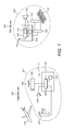
- FIG. 1 An example of an apparatus for inspecting a test object remotely is shown in Figure 1 .
- the apparatus is formed of two parts: a first part 101 located at an inspection site 102 and a second part 103 located at a remote site 104.
- the first part of the inspection apparatus comprises an inspection device 105.
- the inspection device is suitably capable of gathering information about a range of different materials, including metals, plastics, composites, carbon fibre etc.
- the inspection device is preferably capable of being operated by a non-expert.
- a "non-expert" may be someone who is not authorised to perform inspection procedures on a particular test object without supervision.
- the test object in this example is aeroplane 112
- the non-expert may be a local mechanic who has not been certified by the aeroplane's owners as being authorised to undertake repair decisions with respect to the aeroplane.
- the expert will typically be someone who does have the appropriate authorisation.
- the expert is thus able to make decisions on the basis of inspection data. Those decisions could include whether an aeroplane is fit to fly, for example, or whether it needs to be repaired, in which case the expert may decide what type of repair is appropriate.
- the expert will often not be in the same place as the aeroplane.
- the expert can thus be considered to be remotely located: the expert is located at a sufficient distance from the test object that he cannot undertake the physical inspection himself and is reliant on the non-expert to gather the necessary inspection data. It is thus likely that the inspection data will have to be transferred from the inspection site to the remote expert's location via a communication link. This link may be wired or wireless.
- the inspection device 105 gathers data that indicates the condition of the test object.
- This data may be representative of a material structure of the test object beneath its surface.
- the inspection device is capable of non-destructive testing, i.e. evaluating the material under test without causing damage. Suitable non-destructive testing techniques include magnetic particle, liquid penetrant, eddy current testing and low coherence inferometry.
- the inspective device uses ultrasound to gather information about the test object.
- the inspection device may be configured to fire a series of ultrasound pulses at the test object and receive reflections of those pulses back from the test object.
- the reflected pulses can be used to make inferences about the sub-surface structure of the test object and particularly about issues such as voids, delamination and impact damage, some of which may not be visible on the surface.
- inspection data generated by the inspection device is used to generate images of the test object. These images may include one or more of A-scans, B-scans, C-scans and 3D representations.
- Data gathered by the inspection device will usually have to be processed before it can be used to form other images or other useful output.
- This processing might be performed at the inspection site or at the remote site. It might be performed in the inspection device itself or in an associated computing device (not shown).
- the requiring processing may include one or more of filtering, time averaging, thresholding, signal envelope estimation, normalisation, image generation etc.
- filtering time averaging, thresholding, signal envelope estimation, normalisation, image generation etc.
- the term "inspection data” is used herein to refer generally to any data that originates with the inspection device, irrespective of what form that data takes or whether it has been processed after being captured by the inspection device.
- the apparatus at the inspection site may be provided with a user interface, such as a display, that the non-expert can use to view images generated by the inspection device.
- a user interface is not shown in Figure 1 .
- a user interface is shown as being part of the inspection apparatus 104 at the remote site.
- the user interface takes the form of a keyboard 117 and a display 114, both of which might form part of a PC or other computing device.
- the user interface is preferably configured to present inspection data gathered by the inspection device to the remote expert. In one example this presentation takes the form of an image or video shown on a display but any other suitable form of presentation might be used.
- the inspection apparatus at the inspection and remote sites are configured to exchange data via a wireless link.
- the connection between the two sites will be via a wire.
- the link could be a combination of wired and wireless, e.g. the inspection apparatus might communicate wirelessly with a router, which routes data to the remote site over the internet.
- Both apparatus include a respective communicator 106, 115.
- the communicator 106 comprises a communication unit 109 that is connected to receive inspection data from inspection device 105.
- the communication unit is also connected to an antenna 111.
- the communication unit may be configured to communicate data according to any suitable protocol.
- the communication unit is configured for wireless communication, so an appropriate protocol might be WiFi, Bluetooth, LTE, GSM etc., possibly utilizing Web Real Time Communications (Web RTC) protocol or similar. WebRTC is described in more detail below.
- the communicator 115 at the inspection site is similarly arranged, comprising antenna 113 and communication unit 116.
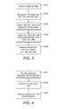
- communication unit 109 may be configured to divide the data that it receives from the inspection device into "real-time” data and "non-real time” data. This process is shown in Figure 2 .
- the communication unit identifies which data should be presented to the remote expert substantially in real-time and which can be presented in non-real time (step S201).
- the "real-time” data is transferred for being presented to the remotely-located apparatus at a first time (step S202).
- the aim of this transfer is to facilitate substantially real-time monitoring of the inspection by the expert.
- the "first time” will not be exactly the same as the time at which the data is captured by the inspection device because it inevitably takes some time to process that data into a form that can be presented to the remote expert and to transfer data between the two sites.
- the presentation of the data to the remote expert therefore preferably occurs in "substantially real-time", so that the data is presented quickly enough after the capture of the inspection data for the remote expert to be able to issue meaningful instructions/guidance to the expert who is handling the inspection device.
- the remaining data is "non-real time” data.
- the communication unit transfers it for being presented to the remotely-located expert at a second time (step S203).
- the second time is preferably later than the first time, i.e. the non-real time data will be available for monitoring by the remote expert at a later time than the "real-time".
- the non-real time data will be data that the expert can use to gain a more detailed understanding of the condition of the test object.
- the non-real time data may represent a more complex type of image than the non-real time data, such as a 3D representation, or a time-data series, compared with an A-scan image.
- the inspection apparatus there are a number of different options for the inspection apparatus to manage the transfer of inspection data to the remote site. Some of these options are shown in Figure 2 .
- One option is for the communication unit just to divide the data up so that the real-time data has fewer bytes than the non-real time data, enabling it to be transferred more quickly across a given communication link (step S204).
- the real-time data may have been subject to extra processing compared with the non-real-time data (step S205).
- the non-real time data may be "raw" data, subject to only a minimal amount of processing after its capture by the inspection device.
- the expert may be able to manipulate this data at the remote location, so the raw data can enable the expert to undertake a more detailed analysis of the test object than is possible from the non-real time data alone.
- a processing unit 120 may be provided in the remote apparatus for this purpose.
- Other options involve the communication unit prioritising the transfer of real-time data.
- another option is for the communication unit to transfer the non-real time data after the real-time data (step S206).
- the non-real time data may only be transferred when the inspection device ceases to capture new data.
- the inspection apparatus may comprise a buffer configured to store non-real time data before it is transferred (this buffer is represented by memory 107 in Figure 1 ).
- the communication unit might also transfer the real-time data at a higher data rate than the non-real time data (step S207). This might free up some capacity over the communication link for other data (e.g. real-time data). All of the preceding options would enable the real-time and non-real time data to be transferred over the same communication link, but the two types of data could equally be transferred across different communication links.
- the communication unit may transfer the real-time data over a higher capacity communication link that the non-real time data (step S208). It should be understood that the communication unit might readily combine two or more of the methods shown at S204 to S208 in Figure 2 , as well as implementing them individually.
- the inspection apparatus at the remote site may also have a role to play in how inspection data is presented to the remote expert.
- the remote inspection apparatus shown in Figure 1 includes a division unit 119.
- the division unit may recognise non-real time and/or real-time data in that inspection data (steps S301 and S302). It may then cause the real-time data to be presented to the expert at a first time (step S303). Suitably this presentation occurs directly upon the division unit recognising the real-time data so that it is presented without unnecessary delay.
- the non-real time data is preferably presented at a later time (step S304).
- the non-real time data may be buffered in the meantime (e.g. using memory 117 shown in Figure 1 ). In some implementations the non-real time data may only be presented to the expert when the expert requests it (step S305).
- the non-real time data may be provided to facilitate more in depth analysis of the inspection data by the expert.
- One option is for the expert to manipulate the non-real time data to observe different aspects of the test object.
- the expert could, for example, adjust the time gates or change the filtering applied to the data to reveal different sections/aspects of the test object's condition.
- the expert is thus able to apply additional processing to the non-real time data, which may have originally been delivered to the remote inspection apparatus in a substantially unprocessed (raw) state.
- the inspection apparatus preferably includes a means for capturing video and sound so that the expert can: (i) watch the non-expert perform the inspection; and (ii) offer advice and issue instructions via a two-way voice link.
- the apparatus in Figure 1 thus includes a video camera 104 and a microphone/loudspeaker arrangement 103.
- a corresponding microphone/loudspeaker arrangement 118 forms part of the remote apparatus.
- the arrangement shown in Figure 1 thus envisages three different types of data being exchanged between the two sites: inspection data relating to the test object, audio data and video data.
- the microphone/loudspeaker arrangement might be provided by a mobile phone, with the video and inspection data being transmitted provided separately.
- all three types of data might be transmitted using the WebRTC protocol, which supports the transfer of audio, video and data simultaneously.
- the apparatus at the two sites are preferably connected via a peer-to-peer arrangement.
- a server architecture is probably most suited to connecting "observers" into the inspection.
- the remote expert's computer may be capable of providing multiple channels that observers can use to follow the inspection. In most implementations the observers are unlikely to exercise any control over the inspection process.
- the observers could be, for example, members of an insurance company that insures aeroplane 112, members of a local authority responsible for certifying experts, more junior inspectors who are training to become certified etc.
- the apparatus preferably enables the expert to exert more direct control over the inspection process.
- Camera 104 is preferably a PTZ (Pan-Tilt-Zoom) device configured to produce a live feed of video images under the control of the expert. This enables the expert to watch the non-expert carry out the inspection.
- PTZ Pan-Tilt-Zoom
- the expert may also be able to control settings on the inspection device. Examples of such settings might include pulse shapes or time gates. It may also be advantageous for the expert to have a degree of control over where the inspection device is placed on the test object. If the inspection device were under the control of a robot, such control would be straightforward, but robots are expensive and still have limited capabilities. The expert does have the ability to instruct the non-expert via the two-way communication link, but this does not precisely pinpoint a location on the test object where expert wishes the inspection device to be placed.
- the method comprises providing the inspection apparatus with a visual guide (step S401).
- a control input is then received from the remote expert (step S402) and the visual guide is used to translate this control input into a visual indication for the non-expert about where to place the inspection device (step S403). Often this will take the form of a direction in which the expert wants the non-expert to move the inspection device.
- the visual guide includes some form of projection device.
- the projection device projects the visual indication for the non-expert onto the test object.
- An example of such a device is shown in Figure 1 .
- the visual guide is a laser pointer 106 attached to camera 104. This is a convenient arrangement because: (i) the remote expert already has control of the direction in which the camera points; and (ii) since the camera and the laser are attached, they will point in the same direction, meaning that the expert should be able to see the projection of the laser onto the surface of the test object in the live video stream. Other arrangements are also possible, and the projection device could be controlled separately from the camera.
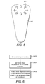
- Another option for the visual guide is shown in Figure 5 .
- the inspection device is provided with a number of visual guides 501 on its back surface 502.
- the visual guides take the form of a series of arrows that can be illuminated by the expert.
- the expert may use the arrow keys on his keyboard, for example, or a joystick, to illuminate the appropriate arrows on the back of the inspection device.
- an inspection device generates inspection data representative of the structure of a material comprised in a test object (step S601).
- the inspection device is capable of "looking" beneath the object's surface so that sub-surface flaws and damage in the material can be detected by the expert.
- This data is suitably used to generate a visual representation of the material structure (step S602).
- a visual representation might be an A-scan, a B-scan, a C-scan or a 3D image.
- the visual representation is suitably generated by some form of image generator.
- the image generator might be comprised within the inspection device or it might form part of a separate computing device (not shown in Figure 1 ).
- a projection device then projects the image of the material structure onto either the test object or a visual representation of that test object (step S603).
- FIG. 7 One example of such a projection device is shown in Figure 7 .
- the projection device is a video projector 701. It is connected to an image generator 702, which is in turn connected to an inspection device 703.
- the test object in this example is a car 704.
- the image generator is suitably configured to provide the video projector with one or more images generated from the inspection data.
- the video generator is then configured to project these onto the surface of the car 705. This provides enhanced situational awareness for both the expert and the non-expert.
- the inspection images are projected onto the same part of the surface of the test object from which the inspection images were generated.
- the projection device is preferably moveable so that this can be achieved. It is preferred that the video projector be automatically moved into the correct position, as this is likely to be more accurate than relying on the non-expert projecting the inspection images onto the correct part of the test object's surface.
- This may be achieved by providing a positioning system as part of the inspection apparatus, which is capable of locating the inspection device within the positioning system and particularly its location in relation to different parts of the test object.
- the positioning system may comprise a series of sensors. These sensors may, for example, be configured to receive shortrange, positioning transmissions from the inspection device.
- the inspection device might have the ability to determine its own position, orientation and depth data.
- FIG. 8 Another example of a projection device is shown in Figure 8 .
- the projection device is a handheld computing device 801. Rather than projecting inspection images onto the surface of the test object itself, in this example the images are projected onto a visual representation of the test object.
- the handheld computing device may comprise a camera 802, so that the visual representation of the test object (car 804) is a video image 803 of that object.
- the visual representation could be a 3D CAD model of the test object.
- the projection device could include a memory storing many of such CAD models, the appropriate one of which can be retrieved in dependence on a type or model number entered by the user. A system of this type may also use information gathered by a positioning system to position the inspection images on the appropriate section of the CAD model or video image.
- the handheld device may incorporate one or more of position, orientation and depth sensors and/or a motion tracking camera so that it can determine its own position relative to the test object (which may be useful if the inspection images are being projected onto a video stream of the test object, for example).
- position, orientation and depth sensors and/or a motion tracking camera so that it can determine its own position relative to the test object (which may be useful if the inspection images are being projected onto a video stream of the test object, for example).
- the projection device may also be used remotely if the appropriate data is communicated to it.
- the projection device might be implemented on a PC of the remote expert.
- Another way in which the inspection procedure may be improved is by incorporating the underlying structure of the test object into the inspection.
- a test object where damage is less significant than others. Impact damage in the material of an aeroplane may be less significant if it is in a part of the aeroplane that is significantly reinforced, for example. Conversely there may be some parts of an aeroplane that are inherently weaker due to the aeroplane's underlying structure. It may be beneficial to incorporate the test objects underlying structure into either of the projection examples described above. Another option is for areas of earlier damage and/or repair to be highlighted. For example, part of the internal structure of the test object may be projected onto the corresponding section of its surface, either alone or in combination with one or more inspection images.
- the internal structure of a test object may be projected onto a video stream or CAD model of the exterior of the test object.
- the same approach may be taken with projections highlighting areas of previous damage and/or repair.
- these new images may be combined with the inspection images.
- the images of the object's underlying structure are preferably pre-generated and may be stored in the inspection apparatus under a type or model number corresponding to the particular test object. Records of previous damage and/or repair may be available from an inspection log relating to the particular object being inspected.
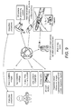
- FIG. 9 An overview of an inspection system is shown in Figure 9 .
- the overview incorporates some of the projection examples described above.
- the system is illustrated for an implementation in which a remote expert is supervising a non-expert on-site. It should be understood, however, that the projection examples described above may equally be advantageously implemented in a straightforward inspection scenario in which the inspection is just performed on-site, with no remote supervision.
- FIG. 10 A further overview of an inspection system is shown in Figure 10 .
- This illustration exemplifies the transfer of data between the inspection site and the remote site. It also illustrates the type of information that may be provided, generated and stored as part of a typical inspection process.
- An example of information that may be provided to the non-expert and/or the expert include the inspection procedures stored in memory 1001. Examples of information that may be generated as part of the inspection process include inspection results (e.g. any repair decisions that have been made), inspection reports, inspection images and raw data. These are shown as being stored in memory 1002 in Figure 10 .
- An inspection log may also be kept, and this may include audio and video images from the inspection (see memory 1003).
- An expert and operator catalogue 1004 may also form part of the inspection system. In Figure 10 , this catalogue is represented by memory 1004.
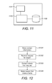
- the expert and operator catalogue shown in Figure 10 may be implemented by a directory, such as that shown in Figure 11 .
- the role of the directory is to assist in connecting a non-expert inspector with a remotely-located expert.
- the directory comprises a communication unit 1101, a memory 1102 and a selection unit 1103.
- the memory is preferably configured to store a database of experts, along with their credentials. These credentials may include, for example, the experts' qualifications, a list of companies or authorities they are certified by, types of object they are qualified to inspect (e.g. aircraft or cars of specific types), earlier experience with relevant structures or test objects etc.
- the database may also store other relevant information, such as the experts' current availability, time zone, normal working hours etc.
- the database preferably also includes contact information for each expert.
- step S1201 contact information is stored for a plurality of experts.
- step S1202 the communication unit receives a request for an expert. That request may have been sent by an inspection apparatus automatically, semi-automatically or in response to manual input.
- the selection unit extract, from the request, one or more criteria specifying the type of expert that is required.
- the selection unit is preferably configured to extract, from the request, criteria including one or more of: a location of the inspection apparatus, a type of test object being inspected by the inspection apparatus, an owner of the test object being inspected by the inspection apparatus and any legal requirement governing the inspection of the test object.
- the selection unit searches the memory for one or more experts that meet the criteria (step S1204).
- the selection unit prioritises some criteria over others. For example, the selection unit preferably only selects experts that have the necessary credentials for the inspection.
- the selection unit may select him anyway if no other appropriately qualified experts are available. This is particularly applicable if the database indicates when an expert who is currently unavailable is likely to become free again, and that information indicates that the expert having the appropriate qualifications is likely to be available within a predetermined period of time.
- the selection unit may return contact details for the selected experts (step S1205) or, in a preferred embodiment, connect the requesting inspection apparatus to an appropriate expert automatically (step S1206).
- the inspection apparatus may send the request for an expert without the user having to expressly request it. For example, if the user asks the inspection apparatus for a remote inspection procedure, that may trigger the inspection apparatus to automatically request the expert details, appropriate inspection procedures etc. from other parts of the system. The user may only be required to enter basic information such as the type or model number of the object to be tested. In one example, if the directory returns contact information for one or more experts to the inspection apparatus, the inspection apparatus may automatically select an expert and effect the connection. This may cause a connection request to be sent to the remote inspection apparatus, which the remote expert may choose to accept or not.
- the inspection apparatus may be implemented together with a positioning system. Providing an inspection apparatus with a positioning system can have other uses too, such as determining the position of the inspection device relative to the test object.
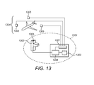
- An illustration of such a system is shown in Figure 13 .
- the inspection apparatus shown generally at 1301, comprises inspection device 1302 and a database 1303.
- Database 1302 may be configured to store configuration data and/or test object records.
- Inspection apparatus 1301 also comprises a position determination unit 1307 that is configured to use information gathered by the positioning system to determine the position of inspection device 1302 relative to test object 1308.
- the inspection apparatus also comprises configuration unit 1306 that is configured to select appropriate configuration data from database 1303 and use it to configure inspection device 1302.
- the configuration unit may also use information from the database to generate configuration data where needed, optionally in conjunction with user input and/or previous inspection results.
- the database 1303, configuration unit 1306 and position determination unit 1307 are shown in Figure 13 as being comprised in a separate housing from the inspection device. They could, for example, be implemented by any suitable computing device, e.g. a PC, laptop, server etc. They might also be implemented together with other functional units, e.g. as part of communicator 106 shown in Figure 1 .
- the computing device is preferably configured to communicate with the inspection device (and the positioning system) via a wired or wireless connection. In other implementations these functional units could be implemented within inspection device 1302.
- FIG. 13 shows an example of a time-of-flight positioning system in which the position of an object is determined by measuring the time that signals take to travel between a transmitted and a receiver.
- the transmitter may be comprised in inspection device 1302 and the receivers comprised in sensors 1305 or vice versa.
- three time measurements are required to determine the three-dimensional position of an object.
- Another option is a spatial scan system, which uses beacons and sensors.
- the sensor may be in the inspection device and the beacon on the test object or elsewhere in the test environment or vice versa. This type of positioning system measures the angle between the beacon and the sensor to determine the position of the inspection device.
- the inspection device may comprise an intertial sensing system such as one that measures rotation and/or position with a gyroscope and/or accelerometer.
- This type of system may not require any external sensors or references.
- An intertial sensing system will normally determine the inspection device's position relative to a known starting position, which could be a fixed point on a test object, such as the tail fin of an aeroplane.
- the positioning system may use one or more of optical signals, ultrasonic signals or radio waves.
- the positioning system might also be a hybrid system that uses a combination of two or more different positioning technologies.
- the inspection apparatus may be configured to use information about the position of the inspection device relative to the test object to provide the inspection device with configuration data appropriate to the particular part of the test object that the inspection device assumes, from the inspection device's position, is about to be inspected.
- the configuration data is information that the inspection device can use to configure itself in the most appropriate way for that part of the test object.
- the aim is to automatically configure the inspection device to the part of the test object being tested, so that it generates the most accurate information possible about the condition of the test object and the material structure beneath its surface.
- Configuration data might include, for example, one or more of: software routines, control settings, set-up information, operational parameters etc. More specifically, configuration data might include pulse shapes, time gate settings, pulse timings, pulse amplitudes etc.
- the inspection apparatus device suitably has access to information detailing which configuration data is applicable to which particular part of a test object.
- information is stored in database 1303.
- the database may be stored elsewhere, and the inspection apparatus may access it remotely via a wired or wireless connection.
- the information is preferably pre-generated, so that all the inspection apparatus has to do is access a record that gives the appropriate configuration data for a particular part.
- configuration data could be generated by the inspection apparatus during the inspection procedure.
- the inspection apparatus may have access to a database of test objects, their respective parts and the relevant qualities of each and have the capability to select appropriate configuration data for each part accordingly.
- Relevant qualities may include information such as part type, part number, part structure, material etc. This type of information will generally be applicable across a particular class of test objects (e.g. a particular make and model of car or aeroplane).
- Other qualities in the database may be specific to a particular test object. For example, maintenance records for that particular test object, which may include details of previous damage or repairs.
- the inspection apparatus may also be configured to select appropriate configuration data for the inspection device in dependence on user input (e.g. input from the inspector and/or a remote expert) and/or configuration data generated by the inspection device earlier in the inspection.
- user input e.g. input from the inspector and/or a remote expert
- the inspection apparatus may be configured to supply the user with a list of possible parts to be inspected dependent on the position of the inspection device relative to the test object. The user may then select which of the parts he wants to inspect. This may be particularly applicable to complex test objects where more than one potential inspection target may lie below a particular position on the object's surface. Each potential inspection target may be associated with its own optimal configuration of the inspection device. The same mechanism may also be used if the accuracy with which the inspection apparatus is able to locate the inspection device means that its calculated position can be associated with several different parts of the test object.
- the positioning process may optionally be triggered by user input (step 1401), e.g. by a user pressing a button on the inspection device when he is in position.
- the method comprises the positioning system then gathering position data associated with the inspection device (step 1402). This may include gathering data from various sensors positioned throughout the test environment or in the inspection device itself, in accordance with the particular positioning system that is being used. This data is then used to determine a position of the inspection device relative to the test object as a whole (step 1403). This step is suitably performed using the position data gathered in the preceding step.
- the position calculation itself may be performed by the positioning system, the inspection apparatus or may be divided between the two.
- the inspection apparatus preferably has the plans, dimensions, configurations etc of the test object available to it in its database so that the position of the inspection device relative to the object can be determined.
- the inspection device is therefore likely to be best placed to determine the position of the inspection device relative to the test object, although in some implementations it could pass the appropriate test object plans to the positioning system for it to perform the calculation.
- This enable a list of one or more possible inspection targets to be identified (step 1404). This list may, for example, take the form of a list of parts. If more than one possible targets is identified (step 1405) and they are associated with different configurations (step 1406), then user may select which of the available options he wants to inspect (step 1407). These steps are optional, as in some implementations only one inspection target will be identified.
- the appropriate configuration data is then selected and provided to the inspection device in order that in can configure itself in accordance with that configuration data (step 1405).
- the inspection device configures itself in accordance with the configuration data (step 1405).
- the inspection can then be commenced using the appropriately configured inspection device (step 1406).
- the test environment may be configured to assist the user in placing the test object in a predetermined location and with a predetermined orientation to assist with the position calculations. For example, this may just take the form of markings on the floor of an inspection bay to mark out how an aeroplane/car should be parked for the inspection.
- One advantage of using information from a positioning system in the way described above is that it enables the inspection device to be automatically configured for the inspection.
- the input of a remote expert is not necessarily required to configure the inspection device appropriately for an untrained inspector, although a remote expert may still participate in the inspection.
- the structures shown in the figures herein are intended to correspond to a number of functional blocks in an apparatus. This is for illustrative purposes only. The figures are not intended to define a strict division between different parts of hardware on a chip or between different programs, procedures or functions in software. In some embodiments, some or all of the procedures described herein may be performed wholly or partly in hardware.
- the communication unit, division unit, image generator, projection device and selection unit may be implemented by a processor acting under software control. Any such software is preferably stored on a non-transient computer readable medium, such as a memory (RAM, cache, FLASH, ROM, hard disk etc.) or other storage means (USB stick, FLASH, ROM, CD, disk etc). Any of the functional units described herein, and the directory in particular, might be implemented as part of the cloud.
Landscapes
- Physics & Mathematics (AREA)
- Engineering & Computer Science (AREA)
- General Physics & Mathematics (AREA)
- General Health & Medical Sciences (AREA)
- Health & Medical Sciences (AREA)
- Pathology (AREA)
- Chemical & Material Sciences (AREA)
- Analytical Chemistry (AREA)
- Biochemistry (AREA)
- Life Sciences & Earth Sciences (AREA)
- Immunology (AREA)
- Signal Processing (AREA)
- Acoustics & Sound (AREA)
- Theoretical Computer Science (AREA)
- Medical Informatics (AREA)
- Computer Networks & Wireless Communication (AREA)
- Computing Systems (AREA)
- Probability & Statistics with Applications (AREA)
- Quality & Reliability (AREA)
- General Engineering & Computer Science (AREA)
- Automation & Control Theory (AREA)
- Investigating Materials By The Use Of Optical Means Adapted For Particular Applications (AREA)
- Testing Or Calibration Of Command Recording Devices (AREA)
- Management, Administration, Business Operations System, And Electronic Commerce (AREA)
Priority Applications (2)
| Application Number | Priority Date | Filing Date | Title |
|---|---|---|---|
| PL15184642T PL2999190T3 (pl) | 2014-09-17 | 2015-09-10 | Zdalne badanie nieniszczące |
| EP20154473.1A EP3664413A1 (fr) | 2014-09-17 | 2015-09-10 | Tests non destructif à distance |
Applications Claiming Priority (2)
| Application Number | Priority Date | Filing Date | Title |
|---|---|---|---|
| GBGB1416443.8A GB201416443D0 (en) | 2014-09-17 | 2014-09-17 | Remote non-destructive testing |
| GBGB1509435.2A GB201509435D0 (en) | 2014-09-17 | 2015-06-01 | Remote non-destructive testing |
Related Child Applications (2)
| Application Number | Title | Priority Date | Filing Date |
|---|---|---|---|
| EP20154473.1A Division-Into EP3664413A1 (fr) | 2014-09-17 | 2015-09-10 | Tests non destructif à distance |
| EP20154473.1A Division EP3664413A1 (fr) | 2014-09-17 | 2015-09-10 | Tests non destructif à distance |
Publications (3)
| Publication Number | Publication Date |
|---|---|
| EP2999190A2 true EP2999190A2 (fr) | 2016-03-23 |
| EP2999190A3 EP2999190A3 (fr) | 2016-04-27 |
| EP2999190B1 EP2999190B1 (fr) | 2020-05-13 |
Family
ID=51869758
Family Applications (2)
| Application Number | Title | Priority Date | Filing Date |
|---|---|---|---|
| EP20154473.1A Withdrawn EP3664413A1 (fr) | 2014-09-17 | 2015-09-10 | Tests non destructif à distance |
| EP15184642.5A Active EP2999190B1 (fr) | 2014-09-17 | 2015-09-10 | Tests non destructif à distance |
Family Applications Before (1)
| Application Number | Title | Priority Date | Filing Date |
|---|---|---|---|
| EP20154473.1A Withdrawn EP3664413A1 (fr) | 2014-09-17 | 2015-09-10 | Tests non destructif à distance |
Country Status (5)
| Country | Link |
|---|---|
| US (3) | US10503157B2 (fr) |
| EP (2) | EP3664413A1 (fr) |
| ES (1) | ES2800504T3 (fr) |
| GB (2) | GB201416443D0 (fr) |
| PL (1) | PL2999190T3 (fr) |
Cited By (1)
| Publication number | Priority date | Publication date | Assignee | Title |
|---|---|---|---|---|
| WO2020084117A1 (fr) * | 2018-10-26 | 2020-04-30 | Dolphitech As | Système de balayage à ultrasons pour l'imagerie d'un objet |
Families Citing this family (5)
| Publication number | Priority date | Publication date | Assignee | Title |
|---|---|---|---|---|
| GB201416443D0 (en) * | 2014-09-17 | 2014-10-29 | Dolphitech As | Remote non-destructive testing |
| US10187686B2 (en) | 2016-03-24 | 2019-01-22 | Daqri, Llc | Recording remote expert sessions |
| EP3694780B1 (fr) * | 2017-10-11 | 2023-04-12 | Bombardier Inc. | Appareil et procédé d'aide au test fonctionnel de systèmes d'aéronef |
| US10746625B2 (en) * | 2017-12-22 | 2020-08-18 | Infineon Technologies Ag | System and method of monitoring a structural object using a millimeter-wave radar sensor |
| WO2024104598A1 (fr) * | 2022-11-18 | 2024-05-23 | Siemens Aktiengesellschaft | Procédé et installation pour l'exécution d'un examen ut local |
Family Cites Families (45)
| Publication number | Priority date | Publication date | Assignee | Title |
|---|---|---|---|---|
| US3778756A (en) | 1972-09-01 | 1973-12-11 | Gen Electric | Method and apparatus for visual imaging of ultrasonic echo signals utilizing a single transmitter |
| US3895525A (en) | 1973-10-03 | 1975-07-22 | Gen Electric | Acoustic imaging apparatus for visual display with depth perception |
| GB2109555B (en) | 1981-11-16 | 1985-09-04 | Raymond Engineering | Ultrasonic testing method and apparatus |
| US4441369A (en) | 1982-09-30 | 1984-04-10 | General Electric Company | Ultrasonic detection of extended flaws |
| JPS60102554A (ja) | 1983-11-09 | 1985-06-06 | Hitachi Ltd | 超音波探触子 |
| JPS60102553A (ja) | 1983-11-09 | 1985-06-06 | Hitachi Ltd | 電子走査型超音波探傷装置 |
| US5383366A (en) | 1992-10-26 | 1995-01-24 | The United States Of America As Represented By The Secretary Of The Navy | Ultrasonic two probe system for locating and sizing |
| GB2286678B (en) | 1994-02-18 | 1998-08-19 | Technical Software Consultants | A probe for an ACFM uniform field array testing system |
| JPH0875714A (ja) | 1994-09-02 | 1996-03-22 | Hihakai Kensa Kk | 探傷試験方法及び探触子 |
| US5773811A (en) | 1994-10-11 | 1998-06-30 | Schramm, Jr.; Harry F. | Method for marking, capturing and decoding machine-readable matrix symbols using ultrasound imaging techniques |
| US6699187B2 (en) * | 1997-03-27 | 2004-03-02 | Medtronic, Inc. | System and method for providing remote expert communications and video capabilities for use during a medical procedure |
| US6748259B1 (en) | 2000-06-15 | 2004-06-08 | Spectros Corporation | Optical imaging of induced signals in vivo under ambient light conditions |
| JP3579646B2 (ja) | 2000-11-21 | 2004-10-20 | ペンタックス株式会社 | 超音波内視鏡 |
| US6732587B2 (en) | 2002-02-06 | 2004-05-11 | Lockheed Martin Corporation | System and method for classification of defects in a manufactured object |
| US10546253B2 (en) * | 2013-01-22 | 2020-01-28 | General Electric Company | Realtime inspection management |
| US7222514B2 (en) | 2004-06-21 | 2007-05-29 | The Boeing Company | Laminate material testing methods and systems |
| DE602005000297T2 (de) | 2004-07-29 | 2007-06-28 | Fujinon Corporation | Ultraschall-Endoskop |
| US7454973B2 (en) | 2005-04-01 | 2008-11-25 | Hitachi, Ltd. | Ultrasonic inspection method and ultrasonic inspection equipment |
| GB2432671A (en) | 2005-11-29 | 2007-05-30 | Dolphiscan As | Ultrasonic transducer with transmitter layer and receiver layer each having elongated electrodes |
| US7478569B2 (en) | 2005-12-02 | 2009-01-20 | The Boeing Company | Non-destructive inspection system with flexible display and associated method |
| US7617730B2 (en) | 2006-06-28 | 2009-11-17 | The Boeing Company | Ultrasonic inspection and repair mode selection |
| US8255170B2 (en) | 2006-11-02 | 2012-08-28 | The Boeing Company | Remote nondestructive inspection systems and methods |
| US9123189B2 (en) * | 2007-02-12 | 2015-09-01 | The Boeing Company | System and method for point-of-use instruction |
| US20080208061A1 (en) | 2007-02-23 | 2008-08-28 | General Electric Company | Methods and systems for spatial compounding in a handheld ultrasound device |
| WO2008137030A1 (fr) | 2007-05-01 | 2008-11-13 | The Regents Of The University Of California | Transducteur d'imagerie ultrasonore conforme flexible et système |
| US20090082673A1 (en) | 2007-09-26 | 2009-03-26 | Xuanming Lu | Semiconductor matching layer in a layered ultrasound transducer array |
| WO2009081569A1 (fr) | 2007-12-25 | 2009-07-02 | Panasonic Corporation | Appareil de diagnostic à ultrasons |
| JP5329533B2 (ja) | 2008-04-25 | 2013-10-30 | 株式会社日立メディコ | 超音波診断装置 |
| JP2010060520A (ja) | 2008-09-05 | 2010-03-18 | Osaka Prefecture | 超音波の変復調方法並びに距離検出方法、通信方法 |
| US7675045B1 (en) | 2008-10-09 | 2010-03-09 | Los Alamos National Security, Llc | 3-dimensional imaging at nanometer resolutions |
| PL2178025T3 (pl) | 2008-10-14 | 2012-07-31 | Dolphitech As | Ultradźwiękowe urządzenie obrazujące do czytania i dekodowania dających się odczytać maszynowo symboli matrycowych |
| EP2249152A3 (fr) | 2009-05-05 | 2012-09-26 | Olympus NDT | Procédé et système pour dimensionnement de gain de distance utilisant des systèmes de réseau phasés |
| KR101107154B1 (ko) | 2009-09-03 | 2012-01-31 | 한국표준과학연구원 | 초음파 탐상장치의 멀티 탐촉자 유닛 |
| EP2525717A1 (fr) | 2010-01-19 | 2012-11-28 | Koninklijke Philips Electronics N.V. | Appareil d'imagerie |
| US20120136743A1 (en) * | 2010-11-30 | 2012-05-31 | Zonar Systems, Inc. | System and method for obtaining competitive pricing for vehicle services |
| US9182487B2 (en) * | 2011-06-22 | 2015-11-10 | The Boeing Company | Advanced remote nondestructive inspection system and process |
| US9354206B2 (en) | 2011-07-25 | 2016-05-31 | The United States Of America As Represented By The Administrator Of The National Aeronautics And Space Administration | Floating ultrasonic transducer inspection system and method for nondestructive evaluation |
| JP5806568B2 (ja) * | 2011-09-26 | 2015-11-10 | 川崎重工業株式会社 | 水中移動型検査装置及び水中検査設備 |
| US8854958B2 (en) * | 2011-12-22 | 2014-10-07 | Cygnus Broadband, Inc. | Congestion induced video scaling |
| KR101513142B1 (ko) | 2012-04-24 | 2015-04-17 | 히하카이켄사 가부시키가이샤 | 적층체의 박리검사방법 및 박리검사장치 |
| CN102680583A (zh) | 2012-05-23 | 2012-09-19 | 苏州脉科库博环保科技有限公司 | 一种带绝缘性能的刚柔结合压电夹层 |
| US20140139658A1 (en) * | 2012-11-20 | 2014-05-22 | General Electric Company | Remote visual inspection system and method |
| DE202013105252U1 (de) | 2013-11-20 | 2014-02-26 | Dolphitech As | Sensormodul mit anpassungsfähiger Trägerschicht |
| US20150186896A1 (en) * | 2013-12-27 | 2015-07-02 | Oilfield Inspection App Inc. | System and method of relatime inpsection of remote facility |
| GB201416443D0 (en) * | 2014-09-17 | 2014-10-29 | Dolphitech As | Remote non-destructive testing |
-
2014
- 2014-09-17 GB GBGB1416443.8A patent/GB201416443D0/en not_active Ceased
-
2015
- 2015-06-01 GB GBGB1509435.2A patent/GB201509435D0/en not_active Ceased
- 2015-09-10 ES ES15184642T patent/ES2800504T3/es active Active
- 2015-09-10 EP EP20154473.1A patent/EP3664413A1/fr not_active Withdrawn
- 2015-09-10 EP EP15184642.5A patent/EP2999190B1/fr active Active
- 2015-09-10 PL PL15184642T patent/PL2999190T3/pl unknown
- 2015-09-16 US US14/855,931 patent/US10503157B2/en active Active
-
2019
- 2019-11-25 US US16/694,750 patent/US11397426B2/en active Active
-
2022
- 2022-07-20 US US17/869,609 patent/US11762378B2/en active Active
Non-Patent Citations (1)
| Title |
|---|
| None |
Cited By (1)
| Publication number | Priority date | Publication date | Assignee | Title |
|---|---|---|---|---|
| WO2020084117A1 (fr) * | 2018-10-26 | 2020-04-30 | Dolphitech As | Système de balayage à ultrasons pour l'imagerie d'un objet |
Also Published As
| Publication number | Publication date |
|---|---|
| GB201416443D0 (en) | 2014-10-29 |
| US20200125080A1 (en) | 2020-04-23 |
| US20160077522A1 (en) | 2016-03-17 |
| EP2999190B1 (fr) | 2020-05-13 |
| ES2800504T3 (es) | 2020-12-30 |
| US11397426B2 (en) | 2022-07-26 |
| PL2999190T3 (pl) | 2021-05-04 |
| EP3664413A1 (fr) | 2020-06-10 |
| US20220357728A1 (en) | 2022-11-10 |
| GB201509435D0 (en) | 2015-07-15 |
| EP2999190A3 (fr) | 2016-04-27 |
| US10503157B2 (en) | 2019-12-10 |
| US11762378B2 (en) | 2023-09-19 |
Similar Documents
| Publication | Publication Date | Title |
|---|---|---|
| US11762378B2 (en) | Remote non-destructive testing | |
| EP3118618B1 (fr) | Étalonnage automatique d'un équipement d'essai non destructif | |
| CA2778261C (fr) | Determination de positions et d'orientations a l'aide de donnees de mouvement | |
| US8713998B2 (en) | Autonomous non-destructive evaluation system for aircraft structures | |
| US20180129211A1 (en) | Next generation autonomous structural health monitoring and management using unmanned aircraft systems | |
| US20100215212A1 (en) | System and Method for the Inspection of Structures | |
| US20130028478A1 (en) | Object inspection with referenced volumetric analysis sensor | |
| JP6144779B2 (ja) | 検査対象を手動操作で超音波検査する方法及びシステム | |
| US7848894B2 (en) | Non-destructive inspection apparatus | |
| EP3104173A1 (fr) | Technique de détection de forme de fibre optique pour coder des examens nde | |
| US20210344833A1 (en) | Inspection workflow using object recognition and other techniques | |
| CN107972885A (zh) | 用于检查闪电引起的不一致性的装置和方法 | |
| WO2017199273A1 (fr) | Système de recherche | |
| CN110033608A (zh) | 车辆损伤检测的处理方法、装置、设备、服务器和系统 | |
| JP2019082403A (ja) | 検査装置および検査方法 | |
| US20150292916A1 (en) | A system , method, and apparatus fr encoding non-destructive examination data using an inspection system | |
| Guibert et al. | Smart NDT tools: Connection and automation for efficient and reliable NDT operations | |
| JP7295732B2 (ja) | 音響測定装置およびプログラム | |
| US11550026B2 (en) | Method, apparatus, and system for tracking arbitrary motion of an inspection probe in multiple dimensions | |
| Chong et al. | A new synthetic training environment system based on an ICT-approach for manual ultrasonic testing | |
| JP2023136390A (ja) | 超音波探傷システム及び超音波探傷方法 |
Legal Events
| Date | Code | Title | Description |
|---|---|---|---|
| PUAI | Public reference made under article 153(3) epc to a published international application that has entered the european phase |
Free format text: ORIGINAL CODE: 0009012 |
|
| AK | Designated contracting states |
Kind code of ref document: A2 Designated state(s): AL AT BE BG CH CY CZ DE DK EE ES FI FR GB GR HR HU IE IS IT LI LT LU LV MC MK MT NL NO PL PT RO RS SE SI SK SM TR |
|
| AX | Request for extension of the european patent |
Extension state: BA ME |
|
| PUAL | Search report despatched |
Free format text: ORIGINAL CODE: 0009013 |
|
| AK | Designated contracting states |
Kind code of ref document: A3 Designated state(s): AL AT BE BG CH CY CZ DE DK EE ES FI FR GB GR HR HU IE IS IT LI LT LU LV MC MK MT NL NO PL PT RO RS SE SI SK SM TR |
|
| AX | Request for extension of the european patent |
Extension state: BA ME |
|
| RIC1 | Information provided on ipc code assigned before grant |
Ipc: H04L 29/06 20060101AFI20160318BHEP Ipc: G01N 29/00 20060101ALN20160318BHEP Ipc: G01N 21/00 20060101ALN20160318BHEP Ipc: H04L 29/08 20060101ALI20160318BHEP |
|
| 17P | Request for examination filed |
Effective date: 20161025 |
|
| RBV | Designated contracting states (corrected) |
Designated state(s): AL AT BE BG CH CY CZ DE DK EE ES FI FR GB GR HR HU IE IS IT LI LT LU LV MC MK MT NL NO PL PT RO RS SE SI SK SM TR |
|
| STAA | Information on the status of an ep patent application or granted ep patent |
Free format text: STATUS: EXAMINATION IS IN PROGRESS |
|
| 17Q | First examination report despatched |
Effective date: 20190103 |
|
| RIC1 | Information provided on ipc code assigned before grant |
Ipc: G01N 21/00 20060101ALN20190710BHEP Ipc: G01N 29/00 20060101ALN20190710BHEP Ipc: H04L 29/08 20060101ALI20190710BHEP Ipc: H04L 29/06 20060101AFI20190710BHEP |
|
| GRAP | Despatch of communication of intention to grant a patent |
Free format text: ORIGINAL CODE: EPIDOSNIGR1 |
|
| STAA | Information on the status of an ep patent application or granted ep patent |
Free format text: STATUS: GRANT OF PATENT IS INTENDED |
|
| INTG | Intention to grant announced |
Effective date: 20190819 |
|
| RAP1 | Party data changed (applicant data changed or rights of an application transferred) |
Owner name: DOLPHITECH AS |
|
| GRAJ | Information related to disapproval of communication of intention to grant by the applicant or resumption of examination proceedings by the epo deleted |
Free format text: ORIGINAL CODE: EPIDOSDIGR1 |
|
| STAA | Information on the status of an ep patent application or granted ep patent |
Free format text: STATUS: EXAMINATION IS IN PROGRESS |
|
| INTC | Intention to grant announced (deleted) | ||
| RIN1 | Information on inventor provided before grant (corrected) |
Inventor name: SKOGLUND, ESKIL Inventor name: ENDRERUD, JAN OLAV |
|
| GRAP | Despatch of communication of intention to grant a patent |
Free format text: ORIGINAL CODE: EPIDOSNIGR1 |
|
| STAA | Information on the status of an ep patent application or granted ep patent |
Free format text: STATUS: GRANT OF PATENT IS INTENDED |
|
| INTG | Intention to grant announced |
Effective date: 20200109 |
|
| RIC1 | Information provided on ipc code assigned before grant |
Ipc: H04L 29/06 20060101AFI20191218BHEP Ipc: G01N 29/00 20060101ALN20191218BHEP Ipc: H04L 29/08 20060101ALI20191218BHEP Ipc: G01N 21/00 20060101ALN20191218BHEP |
|
| GRAS | Grant fee paid |
Free format text: ORIGINAL CODE: EPIDOSNIGR3 |
|
| GRAA | (expected) grant |
Free format text: ORIGINAL CODE: 0009210 |
|
| STAA | Information on the status of an ep patent application or granted ep patent |
Free format text: STATUS: THE PATENT HAS BEEN GRANTED |
|
| AK | Designated contracting states |
Kind code of ref document: B1 Designated state(s): AL AT BE BG CH CY CZ DE DK EE ES FI FR GB GR HR HU IE IS IT LI LT LU LV MC MK MT NL NO PL PT RO RS SE SI SK SM TR |
|
| REG | Reference to a national code |
Ref country code: GB Ref legal event code: FG4D |
|
| REG | Reference to a national code |
Ref country code: CH Ref legal event code: EP |
|
| REG | Reference to a national code |
Ref country code: DE Ref legal event code: R096 Ref document number: 602015052658 Country of ref document: DE |
|
| REG | Reference to a national code |
Ref country code: AT Ref legal event code: REF Ref document number: 1271710 Country of ref document: AT Kind code of ref document: T Effective date: 20200615 |
|
| REG | Reference to a national code |
Ref country code: SE Ref legal event code: TRGR |
|
| REG | Reference to a national code |
Ref country code: NL Ref legal event code: FP |
|
| REG | Reference to a national code |
Ref country code: NO Ref legal event code: T2 Effective date: 20200513 |
|
| REG | Reference to a national code |
Ref country code: LT Ref legal event code: MG4D |
|
| PG25 | Lapsed in a contracting state [announced via postgrant information from national office to epo] |
Ref country code: PT Free format text: LAPSE BECAUSE OF FAILURE TO SUBMIT A TRANSLATION OF THE DESCRIPTION OR TO PAY THE FEE WITHIN THE PRESCRIBED TIME-LIMIT Effective date: 20200914 Ref country code: GR Free format text: LAPSE BECAUSE OF FAILURE TO SUBMIT A TRANSLATION OF THE DESCRIPTION OR TO PAY THE FEE WITHIN THE PRESCRIBED TIME-LIMIT Effective date: 20200814 Ref country code: FI Free format text: LAPSE BECAUSE OF FAILURE TO SUBMIT A TRANSLATION OF THE DESCRIPTION OR TO PAY THE FEE WITHIN THE PRESCRIBED TIME-LIMIT Effective date: 20200513 Ref country code: LT Free format text: LAPSE BECAUSE OF FAILURE TO SUBMIT A TRANSLATION OF THE DESCRIPTION OR TO PAY THE FEE WITHIN THE PRESCRIBED TIME-LIMIT Effective date: 20200513 Ref country code: IS Free format text: LAPSE BECAUSE OF FAILURE TO SUBMIT A TRANSLATION OF THE DESCRIPTION OR TO PAY THE FEE WITHIN THE PRESCRIBED TIME-LIMIT Effective date: 20200913 |
|
| PG25 | Lapsed in a contracting state [announced via postgrant information from national office to epo] |
Ref country code: HR Free format text: LAPSE BECAUSE OF FAILURE TO SUBMIT A TRANSLATION OF THE DESCRIPTION OR TO PAY THE FEE WITHIN THE PRESCRIBED TIME-LIMIT Effective date: 20200513 Ref country code: RS Free format text: LAPSE BECAUSE OF FAILURE TO SUBMIT A TRANSLATION OF THE DESCRIPTION OR TO PAY THE FEE WITHIN THE PRESCRIBED TIME-LIMIT Effective date: 20200513 Ref country code: BG Free format text: LAPSE BECAUSE OF FAILURE TO SUBMIT A TRANSLATION OF THE DESCRIPTION OR TO PAY THE FEE WITHIN THE PRESCRIBED TIME-LIMIT Effective date: 20200813 Ref country code: LV Free format text: LAPSE BECAUSE OF FAILURE TO SUBMIT A TRANSLATION OF THE DESCRIPTION OR TO PAY THE FEE WITHIN THE PRESCRIBED TIME-LIMIT Effective date: 20200513 |
|
| REG | Reference to a national code |
Ref country code: AT Ref legal event code: MK05 Ref document number: 1271710 Country of ref document: AT Kind code of ref document: T Effective date: 20200513 |
|
| PG25 | Lapsed in a contracting state [announced via postgrant information from national office to epo] |
Ref country code: AL Free format text: LAPSE BECAUSE OF FAILURE TO SUBMIT A TRANSLATION OF THE DESCRIPTION OR TO PAY THE FEE WITHIN THE PRESCRIBED TIME-LIMIT Effective date: 20200513 |
|
| PG25 | Lapsed in a contracting state [announced via postgrant information from national office to epo] |
Ref country code: SM Free format text: LAPSE BECAUSE OF FAILURE TO SUBMIT A TRANSLATION OF THE DESCRIPTION OR TO PAY THE FEE WITHIN THE PRESCRIBED TIME-LIMIT Effective date: 20200513 Ref country code: EE Free format text: LAPSE BECAUSE OF FAILURE TO SUBMIT A TRANSLATION OF THE DESCRIPTION OR TO PAY THE FEE WITHIN THE PRESCRIBED TIME-LIMIT Effective date: 20200513 Ref country code: AT Free format text: LAPSE BECAUSE OF FAILURE TO SUBMIT A TRANSLATION OF THE DESCRIPTION OR TO PAY THE FEE WITHIN THE PRESCRIBED TIME-LIMIT Effective date: 20200513 Ref country code: CZ Free format text: LAPSE BECAUSE OF FAILURE TO SUBMIT A TRANSLATION OF THE DESCRIPTION OR TO PAY THE FEE WITHIN THE PRESCRIBED TIME-LIMIT Effective date: 20200513 Ref country code: RO Free format text: LAPSE BECAUSE OF FAILURE TO SUBMIT A TRANSLATION OF THE DESCRIPTION OR TO PAY THE FEE WITHIN THE PRESCRIBED TIME-LIMIT Effective date: 20200513 Ref country code: DK Free format text: LAPSE BECAUSE OF FAILURE TO SUBMIT A TRANSLATION OF THE DESCRIPTION OR TO PAY THE FEE WITHIN THE PRESCRIBED TIME-LIMIT Effective date: 20200513 |
|
| REG | Reference to a national code |
Ref country code: DE Ref legal event code: R097 Ref document number: 602015052658 Country of ref document: DE |
|
| PG25 | Lapsed in a contracting state [announced via postgrant information from national office to epo] |
Ref country code: SK Free format text: LAPSE BECAUSE OF FAILURE TO SUBMIT A TRANSLATION OF THE DESCRIPTION OR TO PAY THE FEE WITHIN THE PRESCRIBED TIME-LIMIT Effective date: 20200513 |
|
| PLBE | No opposition filed within time limit |
Free format text: ORIGINAL CODE: 0009261 |
|
| STAA | Information on the status of an ep patent application or granted ep patent |
Free format text: STATUS: NO OPPOSITION FILED WITHIN TIME LIMIT |
|
| 26N | No opposition filed |
Effective date: 20210216 |
|
| PG25 | Lapsed in a contracting state [announced via postgrant information from national office to epo] |
Ref country code: MC Free format text: LAPSE BECAUSE OF FAILURE TO SUBMIT A TRANSLATION OF THE DESCRIPTION OR TO PAY THE FEE WITHIN THE PRESCRIBED TIME-LIMIT Effective date: 20200513 |
|
| REG | Reference to a national code |
Ref country code: CH Ref legal event code: PL |
|
| PG25 | Lapsed in a contracting state [announced via postgrant information from national office to epo] |
Ref country code: SI Free format text: LAPSE BECAUSE OF FAILURE TO SUBMIT A TRANSLATION OF THE DESCRIPTION OR TO PAY THE FEE WITHIN THE PRESCRIBED TIME-LIMIT Effective date: 20200513 |
|
| REG | Reference to a national code |
Ref country code: BE Ref legal event code: MM Effective date: 20200930 |
|
| PG25 | Lapsed in a contracting state [announced via postgrant information from national office to epo] |
Ref country code: LU Free format text: LAPSE BECAUSE OF NON-PAYMENT OF DUE FEES Effective date: 20200910 |
|
| PG25 | Lapsed in a contracting state [announced via postgrant information from national office to epo] |
Ref country code: LI Free format text: LAPSE BECAUSE OF NON-PAYMENT OF DUE FEES Effective date: 20200930 Ref country code: BE Free format text: LAPSE BECAUSE OF NON-PAYMENT OF DUE FEES Effective date: 20200930 Ref country code: CH Free format text: LAPSE BECAUSE OF NON-PAYMENT OF DUE FEES Effective date: 20200930 |
|
| REG | Reference to a national code |
Ref country code: DE Ref legal event code: R079 Ref document number: 602015052658 Country of ref document: DE Free format text: PREVIOUS MAIN CLASS: H04L0029060000 Ipc: H04L0065000000 |
|
| PG25 | Lapsed in a contracting state [announced via postgrant information from national office to epo] |
Ref country code: TR Free format text: LAPSE BECAUSE OF FAILURE TO SUBMIT A TRANSLATION OF THE DESCRIPTION OR TO PAY THE FEE WITHIN THE PRESCRIBED TIME-LIMIT Effective date: 20200513 Ref country code: MT Free format text: LAPSE BECAUSE OF FAILURE TO SUBMIT A TRANSLATION OF THE DESCRIPTION OR TO PAY THE FEE WITHIN THE PRESCRIBED TIME-LIMIT Effective date: 20200513 Ref country code: CY Free format text: LAPSE BECAUSE OF FAILURE TO SUBMIT A TRANSLATION OF THE DESCRIPTION OR TO PAY THE FEE WITHIN THE PRESCRIBED TIME-LIMIT Effective date: 20200513 |
|
| PG25 | Lapsed in a contracting state [announced via postgrant information from national office to epo] |
Ref country code: MK Free format text: LAPSE BECAUSE OF FAILURE TO SUBMIT A TRANSLATION OF THE DESCRIPTION OR TO PAY THE FEE WITHIN THE PRESCRIBED TIME-LIMIT Effective date: 20200513 |
|
| PGFP | Annual fee paid to national office [announced via postgrant information from national office to epo] |
Ref country code: SE Payment date: 20220915 Year of fee payment: 8 Ref country code: NO Payment date: 20220926 Year of fee payment: 8 Ref country code: NL Payment date: 20220920 Year of fee payment: 8 Ref country code: IE Payment date: 20220926 Year of fee payment: 8 Ref country code: GB Payment date: 20220913 Year of fee payment: 8 Ref country code: DE Payment date: 20220919 Year of fee payment: 8 |
|
| PGFP | Annual fee paid to national office [announced via postgrant information from national office to epo] |
Ref country code: PL Payment date: 20220906 Year of fee payment: 8 Ref country code: FR Payment date: 20220919 Year of fee payment: 8 |
|
| PGFP | Annual fee paid to national office [announced via postgrant information from national office to epo] |
Ref country code: IT Payment date: 20220916 Year of fee payment: 8 Ref country code: ES Payment date: 20221228 Year of fee payment: 8 |
|
| P01 | Opt-out of the competence of the unified patent court (upc) registered |
Effective date: 20230519 |
|
| REG | Reference to a national code |
Ref country code: DE Ref legal event code: R119 Ref document number: 602015052658 Country of ref document: DE |
|
| REG | Reference to a national code |
Ref country code: SE Ref legal event code: EUG |
|
| REG | Reference to a national code |
Ref country code: NL Ref legal event code: MM Effective date: 20231001 |
|
| GBPC | Gb: european patent ceased through non-payment of renewal fee |
Effective date: 20230910 |
|
| PG25 | Lapsed in a contracting state [announced via postgrant information from national office to epo] |
Ref country code: NL Free format text: LAPSE BECAUSE OF NON-PAYMENT OF DUE FEES Effective date: 20231001 |
|
| PG25 | Lapsed in a contracting state [announced via postgrant information from national office to epo] |
Ref country code: NL Free format text: LAPSE BECAUSE OF NON-PAYMENT OF DUE FEES Effective date: 20231001 |
|
| REG | Reference to a national code |
Ref country code: IE Ref legal event code: MM4A |
|
| PG25 | Lapsed in a contracting state [announced via postgrant information from national office to epo] |
Ref country code: IE Free format text: LAPSE BECAUSE OF NON-PAYMENT OF DUE FEES Effective date: 20230910 |
|
| PG25 | Lapsed in a contracting state [announced via postgrant information from national office to epo] |
Ref country code: GB Free format text: LAPSE BECAUSE OF NON-PAYMENT OF DUE FEES Effective date: 20230910 |
|
| PG25 | Lapsed in a contracting state [announced via postgrant information from national office to epo] |
Ref country code: NO Free format text: LAPSE BECAUSE OF NON-PAYMENT OF DUE FEES Effective date: 20230930 Ref country code: IE Free format text: LAPSE BECAUSE OF NON-PAYMENT OF DUE FEES Effective date: 20230910 Ref country code: GB Free format text: LAPSE BECAUSE OF NON-PAYMENT OF DUE FEES Effective date: 20230910 Ref country code: FR Free format text: LAPSE BECAUSE OF NON-PAYMENT OF DUE FEES Effective date: 20230930 Ref country code: DE Free format text: LAPSE BECAUSE OF NON-PAYMENT OF DUE FEES Effective date: 20240403 |
|
| PG25 | Lapsed in a contracting state [announced via postgrant information from national office to epo] |
Ref country code: SE Free format text: LAPSE BECAUSE OF NON-PAYMENT OF DUE FEES Effective date: 20230911 |