EP2998933B1 - Computer aided diagnosis apparatus and method based on size model of region of interest - Google Patents
Computer aided diagnosis apparatus and method based on size model of region of interest Download PDFInfo
- Publication number
- EP2998933B1 EP2998933B1 EP15185456.9A EP15185456A EP2998933B1 EP 2998933 B1 EP2998933 B1 EP 2998933B1 EP 15185456 A EP15185456 A EP 15185456A EP 2998933 B1 EP2998933 B1 EP 2998933B1
- Authority
- EP
- European Patent Office
- Prior art keywords
- roi
- size
- detected
- state
- current image
- Prior art date
- Legal status (The legal status is an assumption and is not a legal conclusion. Google has not performed a legal analysis and makes no representation as to the accuracy of the status listed.)
- Not-in-force
Links
Images


Classifications
-
- G—PHYSICS
- G06—COMPUTING; CALCULATING OR COUNTING
- G06T—IMAGE DATA PROCESSING OR GENERATION, IN GENERAL
- G06T7/00—Image analysis
- G06T7/0002—Inspection of images, e.g. flaw detection
- G06T7/0012—Biomedical image inspection
-
- A—HUMAN NECESSITIES
- A61—MEDICAL OR VETERINARY SCIENCE; HYGIENE
- A61B—DIAGNOSIS; SURGERY; IDENTIFICATION
- A61B8/00—Diagnosis using ultrasonic, sonic or infrasonic waves
- A61B8/13—Tomography
-
- A—HUMAN NECESSITIES
- A61—MEDICAL OR VETERINARY SCIENCE; HYGIENE
- A61B—DIAGNOSIS; SURGERY; IDENTIFICATION
- A61B8/00—Diagnosis using ultrasonic, sonic or infrasonic waves
- A61B8/56—Details of data transmission or power supply
-
- G—PHYSICS
- G06—COMPUTING; CALCULATING OR COUNTING
- G06T—IMAGE DATA PROCESSING OR GENERATION, IN GENERAL
- G06T7/00—Image analysis
- G06T7/10—Segmentation; Edge detection
- G06T7/12—Edge-based segmentation
-
- G—PHYSICS
- G06—COMPUTING; CALCULATING OR COUNTING
- G06T—IMAGE DATA PROCESSING OR GENERATION, IN GENERAL
- G06T7/00—Image analysis
- G06T7/10—Segmentation; Edge detection
- G06T7/143—Segmentation; Edge detection involving probabilistic approaches, e.g. Markov random field [MRF] modelling
-
- G—PHYSICS
- G06—COMPUTING; CALCULATING OR COUNTING
- G06T—IMAGE DATA PROCESSING OR GENERATION, IN GENERAL
- G06T2207/00—Indexing scheme for image analysis or image enhancement
- G06T2207/10—Image acquisition modality
- G06T2207/10016—Video; Image sequence
-
- G—PHYSICS
- G06—COMPUTING; CALCULATING OR COUNTING
- G06T—IMAGE DATA PROCESSING OR GENERATION, IN GENERAL
- G06T2207/00—Indexing scheme for image analysis or image enhancement
- G06T2207/10—Image acquisition modality
- G06T2207/10132—Ultrasound image
-
- G—PHYSICS
- G06—COMPUTING; CALCULATING OR COUNTING
- G06T—IMAGE DATA PROCESSING OR GENERATION, IN GENERAL
- G06T2207/00—Indexing scheme for image analysis or image enhancement
- G06T2207/30—Subject of image; Context of image processing
- G06T2207/30004—Biomedical image processing
- G06T2207/30096—Tumor; Lesion
Definitions
- CAD Computer Aided Diagnosis
- ROI region of interest
- ultrasound images are used to diagnose patients' conditions.
- Medical practitioners generally apply a probe to a patient's body parts to acquire ultrasound images in real time, check the acquired ultrasound images output to a screen with the naked eye, detect and determine a lesion or a suspected region. If there is a region suspected to include a lesion, medical practitioners move the probe slowly or stop the probe to observe the suspected region.
- the computer aided diagnosis (CAD) system analyzes various medical images to detect lesions, and determines whether detected lesions are benign or malignant to provide the diagnosis results to medical practitioners.
- CAD computer aided diagnosis
- ultrasound imaging diagnosis is performed such that a lesion is first identified using ultrasound, and then is determined by a separate CAD system.
- Research on the real-time CAD system is currently being conducted where a lesion is detected from ultrasound images acquired in real time to diagnose the lesion.
- CAD Computer Aided Diagnosis
- the image receiver may receive in real time ultrasound images acquired through a probe in units of frames.
- the ROI acquirer may include an ROI detector configured to detect one or more ROIs from the current image.
- the ROI acquirer may further include an ROI determiner configured to determine whether a ROI from the one or more detected ROIs is erroneously detected based on the ROI size transition model.
- the determiner may be configured to determine a size state of the detected ROI by matching the size of the detected ROI with the ROI size transition model, and determine that the detected ROI is erroneously detected, in response to determining that a size state of a previous image on the ROI size transition model is not capable of being transformed to the determined size state of the current image.
- the ROI output component may be further configured to not output visual information on the detected ROI.
- the ROI output component may be further configured to determine the biggest size state that is possible to transition from the size state of the previous image using the ROI size transition model, and to output visual information on the detected ROI that has a size corresponding to the biggest size state.
- the ROI acquirer may further include an ROI predictor configured to predict an ROI in the current image using the ROI size transition model, in response to the ROI not being detected from the current image.
- the ROI predictor may determine a size state transitionable from the size state of the ROI acquired from the image before the current image using the ROI size transition model, and to predict the ROI in the current image using the determined size state.
- the ROI size transition model may be created using the Markov model learning based on a change in sizes of ROIs in a sequence of images for each interested item, and the ROI size transition model comprises size states, a transition possibility between the size states, transition direction, and transition probability information.
- the visual information may include first information comprising at least one of square, round, oval, or cross shapes, and second information comprising at least one of color, types of lines, or thickness of lines of the first information.
- the visual information may be output on a screen.
- the ROI acquirer may be configured to detect the one or more ROIs based on geo-spatial location information of the one or more ROIs.
- CAD Computer Aided Diagnosis
- the acquiring of the ROI may include detecting one or more ROI from the current image.
- the acquiring of the ROI may include, determining whether a ROI from the one or more detected ROI is erroneously detected based on the ROI size transition model.
- the determining of the ROI may include determining a size state of the detected ROI by matching the size of the detected ROI with the ROI size transition model, and determining that the detected ROI is erroneously detected, in response to determining that a size state of a previous image on the ROI size transition model is not capable of being transformed to the determined size state of the current image.
- the outputting of the ROI may include, in response to the detected ROI being erroneously detected, the outputting of the ROI comprises not outputting visual information on the detected ROI.
- the outputting of the ROI may include determining the biggest size state that is possible to transition from the size state of the previous image using the ROI size transition model, and outputting visual information on the detected ROI that has a size corresponding to the biggest size state.
- the acquiring of the ROI may include predicting an ROI in the current image using the ROI size transition model in response to the ROI not being detected from the current image.
- the predicting of the ROI may include determining a size state transitionable from the size state of the ROI acquired from the image before the current image using the ROI size transition model, and predicting the ROI in the current image using the determined size state.
- the ROI size transition model may be created using the Markov model learning based on a change in sizes of ROIs in a sequence of images for each interested item, and the ROI size transition model may include size states, a transition possibility between the size states, transition direction and transition probability information.
- FIG. 1 is a diagram illustrating an example of a Computer-Aided Diagnosis (CAD) apparatus.
- CAD Computer-Aided Diagnosis
- the CAD apparatus 100 analyzes ultrasound images acquired in real time through a probe to detect and classify regions of interest (ROIs).
- ROIs regions of interest
- the CAD apparatus 100 is not limited thereto, and may include an apparatus that receives a sequence of images acquired in real time or a sequence of pre-acquired images using various image capturing devices to detect and classify ROIs.
- the CAD apparatus 100 includes an image receiver 110, an ROI acquirer 120, and an ROI output component 130.
- the image receiver 110 sequentially receives images, where the images may be successively captured medical images of examined regions of a subject.
- a user that performs examination applies a probe to a diseased area, such as, for example, lesion, fingers, toes, abdomen, breast, and chest of a subject and moves the probe around the area to acquire images.
- the image receiver 110 may receive the images in real time. Images may be transmitted in units of frames in real time, and the image receiver 110 transmits the images received in real time to the ROI detector 120 for processing.
- the ROI detector 120 may acquire an ROI from a current image every time an image is received.
- the ROI refers to a region that includes items of interest for the purposes of diagnosis, such as, for example, lesion, fingers, toes, abdomen, breast, and chest.
- the ROI detector 120 may acquire an ROI from a current image based on an ROI size transition model.
- the ROI size transition model may be created in advance based on a change in sizes of ROIs in a sequence of images for each ROI.
- the above-described creation of the ROI size transition model is a non-exhaustive example, and other methods of creating the ROI size transition model are considered to be well within the scope of the present disclosure.
- the size model may be created by a user without learning.
- the ROI size transition model may be created by learning, or may be a Markov model that is created in the form of rules.
- the ROI size transition model may include size states, transition possibility between the size states, a transition direction, and transition probability information, which will be described in further detail with reference to FIG. 4 .
- the ROI acquirer 120 may acquire an ROI using an automatic detection algorithm. Upon detecting an ROI, an ROI size transition model may be used to determine whether the ROI is erroneously detected.
- an ROI may be predicted in the current image based on information on an ROI tracked in a previous image and an ROI size transition model.
- the ROI output component 130 outputs an ROI detected by the ROI acquirer 120 to be displayed on a screen. Based on the location and size of the detected ROI, the ROI output component 130 may output an ROI for display on a screen by outputting visual information associated with the ROI at a position that corresponds to a current image output to a screen.
- the visual information may include first information regarding shapes, such as, for example, square, round, oval, and cross.
- the visual information may also include information regarding color, types and thickness of lines, and the like.
- the ROI output component 130 may not output visual information on the ROI if the ROI acquirer 120 determines that an automatically detected ROI is erroneously detected.
- the ROI output component 140 may determine the size state of the ROI appropriate for a current image using an ROI size transition model, and may output on a screen visual information having a size corresponding to the determined size state.
- a maximum possible size state that may be transitioned from the size state of an ROI detected from a previous image may be determined to be a size state appropriate for a current image.
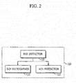
- FIG. 2 is a diagram illustrating an example of a ROI acquirer of FIG. 1 .
- the ROI acquirer 120 includes an ROI detector 121, an ROI determiner 122, and an ROI predictor 123.
- the ROI detector 121 may detect an interested item by applying an detection algorithm of an ROI to a received current image, and may determine a region that includes the interested item to be an ROI.
- the ROI detection algorithm may include algorithms such as, for example, AdaBoost, Deformable Part Models (DPM), Deep Neural Network (DNN), Convolutional Neural Network (CNN), Sparse Coding.
- the algorithm(s) to be applied may be determined depending on factors such as, for example, the performance of the apparatus 100, diagnosis purposes, and diagnosis time.
- the ROI determiner 122 may track the ROI, and determine whether the ROI is identical to an ROI that has been detected from a previous image. In one example, using geo-spatial location information of the detected ROI, the location of the ROI is compared to a location of an ROI detected from a previous image to determine whether the two regions of interest are identical. In another example, it may be determined whether the detected ROI and an ROI that has been tracked are identical to each other using techniques such as, for example, Jaccard similarity algorithm, and Mean shift algorithm.
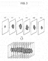
- FIG. 3 is a diagram illustrating an example of an ROI in a sequence of images.
- an item of interest such as a lesion
- an item of interest is generally three-dimensional.
- the size of an three-dimensional ROI is gradually increases from a point in time (t-2) when the ROI is initially detected to a point in time (t+3) when the ROI is lastly detected, and then the size decreases.
- the ROI is small at (t-2) when it is initially detected, and then is gradually increased to a maximum size at a current time (t).
- the size of the detected ROI gradually decreased after the points in time t+1 to t+3.
- the ROI determiner 122 may determine whether the detected ROI is erroneously detected based on a change in size of an ROI.
- the ROI determiner 122 may determine that the ROI is erroneously detected.
- an ROI as illustrated in FIG. 3
- an ROI having a size corresponding to the size of an ROI detected at a point in time t-2 is normally detected, with no possibility of suddenly detecting an ROI having a size bigger than the size, such that it is determined that the ROI is erroneously detected.
- an ROI having a size that is not normal in an image of a current time (t), e.g. a size that is not possible to be detected immediately after a size of an ROI detected from a previous image at t-1 the detected ROI may be determined to be erroneously detected.
- the ROI determiner 122 may determine the size state of a detected ROI by matching the size of an ROI detected from a current image with an ROI size transition model. Once the size state is determined, it is determined whether it is possible to transition from the size state of an ROI detected from a previous image, and based on the determination, it may be determined whether an ROI is erroneously detected.
- the ROI predictor 123 may predict an ROI that is appropriate for a current image using an ROI size transition model.
- an ROI which has been tracked from a previous image, does not suddenly disappear at a certain point.
- the ROI predictor 123 may determine that an ROI, which is to be detected, is not detected, and may predict an ROI having a size appropriate to be detected from a current image.
- the ROI predictor 123 may identify a change in size using ROI tracking information in previous images, i.e., using information on the size of an ROI acquired from a previous image, and may determine a size state that is likely to be detected from a current image on an ROI size transition model. Further, using ROI location information of a previous image, the ROI predictor 123 may determine the location of an ROI in a current image.
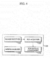
- FIG. 4 is a diagram illustrating an example of a Computer-Aided Diagnosis (CAD) apparatus according to another example.
- the Computer Aided Diagnosis (CAD) apparatus 300 includes an image receiver 310, an ROI acquirer 320, an ROI output component 330, and a model builder 340.
- the above descriptions of FIGS. 1-3 is also applicable to the image receiver 310, the ROI acquirer 320, and the ROI output component 330 shown in FIG. 4 , and is incorporated herein by reference. Thus, the above description may not be repeated here.
- the model builder 340 may build an ROI size transition model based on the change in size of an ROI desired by a user in a sequence of collected images.
- the model builder 340 may collect a sequence of 3D video data successively captured to acquire an ROI, or video data acquired in real time, and may extract ground truth from the collected data to build an ROI size transition model.
- the ground truth may include information, such as, for example, the size of an ROI visual information, the shape of an ROI visual information (such as, for example, a square shape, an oval shape, a round shape, a cross mark), and a number of pixels.
- the model builder 340 may generate an ROI size transition model by a methodology such as, for example, the Markov Model learning based on the extracted ground truth. Further, in the case where a user is well aware of the change in size of an ROI through specialized knowledge, diagnosis experiences, or the like, an ROI size transition model may be directly generated by the user without specific learning.
- FIGS. 5A to 5C are diagrams explaining an ROI size transition model according to an example.
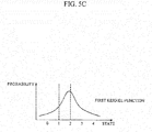
- the model builder 340 may generate a size transition model that includes information such as, for example, size states (0, 1, 2, ..., n-1, and n), probability of transition between the size states (0, 1, 2, ..., n-1, and n), and transition probability information as illustrated in FIG. 5A , in which size state 0 denotes a state where an ROI is not detected, size state 1 denotes the smallest size of an ROI, and size state n denotes the largest size of an ROI.
- the model builder 340 may define, as states 1, 2, 3, and 4, the sizes of the ROIs 51, 52, 53, and 54 detected from each of the four successive image frames f104, f105, f106, and f107.
- the model builder 340 may calculate probability of transition between each state using Equation 1, and the calculated probability of transition between each state is illustrated in FIG. 5C .
- the transition from state 1 to state 2 may be calculated to have the highest probability as illustrated in FIG. 5C .
- B represents the size of a detected ROI
- S represents a size state of the ROI
- D represents a detection score of the ROI
- n denotes frame n
- m denotes an index of the ROI interest detected from frame n.
- B n,m denotes an m th ROI detected from frame n.
- FIGS. 6A and 6B are diagrams explaining acquiring and outputting of an ROI according to an example.
- FIGS. 7A and 7B are diagrams explaining acquiring and outputting of an ROI according to another example.
- FIGS. 6A to 7B illustrate examples of acquiring and outputting an ROI by the Computer Aided Diagnosis (CAD) apparatuses 100 and 300 illustrated in FIGS. 1 and 4 .
- CAD Computer Aided Diagnosis
- FIGS. 6A to 7B will be described with reference to the CAD apparatus 100 illustrated in FIG. 1 , and with reference to an ROI size transition model illustrated in FIG. 5A .
- FIG. 6A is a diagram explaining an abnormally big ROI 62 detected from a current frame f105.
- the size of an ROI detected from a previous frame f104 corresponds to state 1 in an ROI size transition model, and the size of the ROI 62 detected from the current frame f105 corresponds to state 5.
- the ROI acquirer 120 may detect the ROI 62 using an automatic detection algorithm as described above.
- the ROI acquirer 120 may perform matching by comparing the ROI 61 of the previous frame f104 to the ROI 62 of the current frame f105 in terms of a geo-spatial location and using Jaccard similarity. If the ROI 61 of the previous frame f104 is matched with the ROI 62 of the current frame f105, it is determined to be a normal detection. If they are not matched with each other, the size of the ROI 61 is further matched with an ROI size transition model to determine whether it is an erroneous detection.
- the ROI acquirer 120 matches the size of the ROI 62 with an ROI size transition model, and determines the size of the ROI 62 to be equivalent to that of state 5. Since the size of an ROI may not transition from state 1 to state 5, it may be determined to be an erroneous detection.
- the ROI output component 130 determines state 3 to be the biggest possible state to which state 1 of the ROI 61 of the previous frame f104 may transition, and outputs visual information with a size corresponding to the determined size state 3 on a screen to display the ROI 63 of the current image.
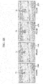
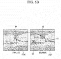
- FIG. 6B is a diagram explaining three ROIs 65, 66, and 67 detected from the current frame f107, in which it is assumed that the size of the ROI 64 detected from the previous frame f106 is 10mm, and the size is state 1 in an ROI size transition model.
- the ROI acquirer 120 matches each of the ROIs 65, 66, and 67 with the ROI 64 in the previous frame f106, in which the matching may be performed in terms of a geo-spatial location and using Jaccard similarity.
- the ROI acquirer 120 may determine that it is a normal ROI that has been continuously tracked from a previous image, without need for an ROI size transition model.
- the ROI output component 120 may output visual information that includes the detected ROI 65 having a size of 12mm on a screen to display the ROI 65.
- the second and third ROIs 66 and 67 detected from the current frame f107 are new ROIs that have not been detected from the previous frame f106, and thus, are not matched with the previous frame f106.
- the ROI acquirer 120 may determine whether the ROIs 66 and 67 are erroneously detected using an ROI size transition model.
- the ROI acquirer 120 may calculate a probability of detecting the ROIs 66 and 67 for the first time, and may determine that the ROIs 66 and 67 are erroneously detected if the calculated detection probability is below a threshold.
- the detection probability may be calculated by considering detection scores calculated when ROIs are detected using an automatic detection algorithm, and considering transition probability on an ROI size transition model, in which the detection probability may be calculated by an equation of detection score times transition probability.
- a detection score of the second ROI 66 is 10
- the size on an ROI size transition model is state 2
- probability of transition from state 0 where no ROI is detected from a previous image to state 2 is 0.05, with detection probability of 0.5 (0.05x10).
- a detection score of the third ROI 67 is 25, and the size is state 1
- probability of transition from state 0 to state 1 is 0.5, with detection probability of 12.5 (0.5x25).
- a predetermined threshold is 10
- the second ROI 66 is below the threshold, and thus is determined to be erroneously detected.
- the ROI output component 130 does not output visual information for displaying the ROI 66. Further, as the ROI 67 is determined to be detected normally, visual information for displaying the ROI 67 is output. In FIG. 6B , the ROI 66 is shown in a box indicated with "X", which means visual information for the ROI 66 is not output.
- FIGS. 7A and 7B are diagrams explaining examples for acquiring and outputting of an ROI according to another example.
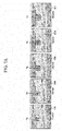
- FIG. 7A illustrates that with respect to five sequentially input frames f107, f108, f109, f110, and f111;, ROIs 71, 72, 73, and 74 which have been detected and tracked from the previous frames f107, f108, f109, and f110 respectively, are not detected from the current frame f111 using an automatic detection algorithm.
- the ROI acquirer 120 may predict an ROI using various types of information calculated by an automatic detection algorithm, e.g., information on candidate regions, detection scores of each of the candidate regions, transition probability for each of the candidate regions, sizes and locations of the ROIs 71, 72, 73, and 74 detected from the previous frames f107, f108, f109, and f110, and the like, so that the ROI 75 may be detected.
- an automatic detection algorithm e.g., information on candidate regions, detection scores of each of the candidate regions, transition probability for each of the candidate regions, sizes and locations of the ROIs 71, 72, 73, and 74 detected from the previous frames f107, f108, f109, and f110, and the like, so that the ROI 75 may be detected.
- the state may transition to any one state of 0, 1, or 2 on an ROI size transition model.
- the ROI acquirer 120 determines whether the size of the ROI normally transitions from 1 to 0.
- the ROI acquirer 120 may select neighboring candidate regions, which are positioned within a predetermined threshold from the center of the ROI 74 of the previous frame f110, from among candidate regions of the current frame f111 calculated using an automatic detection algorithm, and using detection scores and sizes of the selected candidate regions, the ROI acquirer 120 may predict the ROI 75.
- two candidate regions of state 1 and four candidate regions of state 2 are selected from among candidate regions of states 0, 1, and 2 that may transition from the ROI 74 of the previous frame f110.
- the ROI acquirer 120 may predict, as the ROI 75, a region with the highest detection probability (e.g., detection score x transition probability) among the selected candidate regions.
- the ROI output component 130 may output visual information having a size corresponding to the size of the ROI 75 to display the ROI.
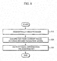
- FIG. 8 and 9 are diagrams illustrating examples of a Computer-Aided Diagnosis (CAD) method.
- FIG. 9 is a diagram illustrating a method of acquiring an ROI.
- the operations in FIGS. 8-9 may be performed in the sequence and manner as shown, although the order of some operations may be changed or some of the operations omitted. Many of the operations shown in FIGS. 8-9 may be performed in parallel or concurrently.
- FIGS. 1-7B is also applicable to FIGS. 8-94 , and is incorporated herein by reference. Thus, the above description may not be repeated here.
- FIGS. 8 and 9 Examples illustrated in FIGS. 8 and 9 may be performed by the Computer Aided Apparatuses (CAD) 100 and 300 illustrated in FIGS. 1 and 4 .
- CAD Computer Aided Apparatuses
- the CAD apparatus sequentially receives images, in which the received images may be ultrasound images acquired through a probe, and may be received in units of frames in real time.
- an ROI is acquired from the received images.
- the ROI may be acquired using a pre-stored ROI size transition model.
- the CAD apparatus detects an ROI from a current image using a pre-stored automatic detection algorithm. Once an ROI desired by a user is detected, in 612, the detected ROI is matched with an ROI detected from a previous image by comparing the ROIs in terms of geo-spatial locations or using Jaccard similarity algorithm. If the ROIs are matched, the detected ROI is determined to be a normal ROI and is output in 619.
- the size state of the detected ROI is determined based on a pre-stored ROI size transition model.
- the detected ROI is output in 619.
- the size state appropriate for a detected ROI may be determined in 617 based on an ROI size transition model.
- An ROI having a size corresponding to the determined size state may be output in 619. For example, if the size state of an ROI detected from a current image may not transition from a size state of an ROI detected from a previous image, the biggest possible size state that may transition from the size state of the ROI of a previous image may be determined to be the size state that may be output.
- an ROI that is appropriate for a current image may be predicted in 618 using a pre-stored ROI size transition model.
- detection probability may be calculated using detection scores and transition probabilities of candidate regions, which are positioned within a predetermined threshold from the center of the ROI detected from the previous image frame using an automatic detection algorithm.
- a candidate region having the highest detection probability may be predicted as an ROI of a current image.
- an ROI is acquired from a current image
- visual information is output, which may be output on a screen to inform a user of the ROI.
- ROIs automatically detected in 520 visual information on an ROI, which has been determined to be erroneously detected, may not be output.
- the size of the detected ROI is matched with an ROI size transition model, so that visual information having a size corresponding to a maximum possible size that may transition from the size of an ROI of a previous image may be output.
- the apparatuses, units, modules, devices, and other components illustrated that perform the operations described herein are implemented by hardware components.
- hardware components include controllers, sensors, generators, drivers and any other electronic components known to one of ordinary skill in the art.
- the hardware components are implemented by one or more processors or computers.
- a processor or computer is implemented by one or more processing elements, such as an array of logic gates, a controller and an arithmetic logic unit, a digital signal processor, a microcomputer, a programmable logic controller, a field-programmable gate array (FPGA), a programmable logic array, a microprocessor, an application-specific integrated circuit (ASIC), or any other device or combination of devices known to one of ordinary skill in the art that is capable of responding to and executing instructions in a defined manner to achieve a desired result.
- a processor or computer includes, or is connected to, one or more memories storing instructions or software that are executed by the processor or computer.
- Hardware components implemented by a processor or computer execute instructions or software, such as an operating system (OS) and one or more software applications that run on the OS, to perform the operations described herein.
- the hardware components also access, manipulate, process, create, and store data in response to execution of the instructions or software.
- OS operating system
- processors or “computer” may be used in the description of the examples described herein, but in other examples multiple processors or computers are used, or a processor or computer includes multiple processing elements, or multiple types of processing elements, or both.
- a hardware component includes multiple processors, and in another example, a hardware component includes a processor and a controller.
- a hardware component has any one or more of different processing configurations, examples of which include a single processor, independent processors, parallel processors, single-instruction single-data (SISD) multiprocessing, single-instruction multiple-data (SIMD) multiprocessing, multiple-instruction single-data (MISD) multiprocessing, and multiple-instruction multiple-data (MIMD) multiprocessing.
- SISD single-instruction single-data
- SIMD single-instruction multiple-data
- MIMD multiple-instruction multiple-data
- FIGS. 8-9 that perform the operations described herein are performed by a processor or a computer as described above executing instructions or software to perform the operations described herein.
- Instructions or software to control a processor or computer to implement the hardware components and perform the methods as described above are written as computer programs, code segments, instructions or any combination thereof, for individually or collectively instructing or configuring the processor or computer to operate as a machine or special-purpose computer to perform the operations performed by the hardware components and the methods as described above.
- the instructions or software include machine code that is directly executed by the processor or computer, such as machine code produced by a compiler.
- the instructions or software include higher-level code that is executed by the processor or computer using an interpreter. Programmers of ordinary skill in the art can readily write the instructions or software based on the block diagrams and the flow charts illustrated in the drawings and the corresponding descriptions in the specification, which disclose algorithms for performing the operations performed by the hardware components and the methods as described above.
- the instructions or software to control a processor or computer to implement the hardware components and perform the methods as described above, and any associated data, data files, and data structures, are recorded, stored, or fixed in or on one or more non-transitory computer-readable storage media.
- Examples of a non-transitory computer-readable storage medium include read-only memory (ROM), random-access memory (RAM), flash memory, CD-ROMs, CD-Rs, CD+Rs, CD-RWs, CD+RWs, DVD-ROMs, DVD-Rs, DVD+Rs, DVD-RWs, DVD+RWs, DVD-RAMs, BD-ROMs, BD-Rs, BD-R LTHs, BD-REs, magnetic tapes, floppy disks, magneto-optical data storage devices, optical data storage devices, hard disks, solid-state disks, and any device known to one of ordinary skill in the art that is capable of storing the instructions or software and any associated data, data files, and data structures in a non-transitory
- the instructions or software and any associated data, data files, and data structures are distributed over network-coupled computer systems so that the instructions and software and any associated data, data files, and data structures are stored, accessed, and executed in a distributed fashion by the processor or computer.
Applications Claiming Priority (1)
| Application Number | Priority Date | Filing Date | Title |
|---|---|---|---|
| KR1020140122908A KR20160032586A (ko) | 2014-09-16 | 2014-09-16 | 관심영역 크기 전이 모델 기반의 컴퓨터 보조 진단 장치 및 방법 |
Publications (3)
| Publication Number | Publication Date |
|---|---|
| EP2998933A2 EP2998933A2 (en) | 2016-03-23 |
| EP2998933A3 EP2998933A3 (en) | 2016-03-30 |
| EP2998933B1 true EP2998933B1 (en) | 2019-08-07 |
Family
ID=54249291
Family Applications (1)
| Application Number | Title | Priority Date | Filing Date |
|---|---|---|---|
| EP15185456.9A Not-in-force EP2998933B1 (en) | 2014-09-16 | 2015-09-16 | Computer aided diagnosis apparatus and method based on size model of region of interest |
Country Status (3)
| Country | Link |
|---|---|
| US (2) | US9805466B2 (ko) |
| EP (1) | EP2998933B1 (ko) |
| KR (1) | KR20160032586A (ko) |
Families Citing this family (35)
| Publication number | Priority date | Publication date | Assignee | Title |
|---|---|---|---|---|
| US9798856B2 (en) * | 2012-03-21 | 2017-10-24 | Koninklijke Philips N.V. | Clinical workstation integrating medical imaging and biopsy data and methods using same |
| US9589374B1 (en) * | 2016-08-01 | 2017-03-07 | 12 Sigma Technologies | Computer-aided diagnosis system for medical images using deep convolutional neural networks |
| CN110168657B (zh) * | 2016-12-05 | 2024-03-12 | 皇家飞利浦有限公司 | 利用智能肿瘤大小更改通知进行肿瘤跟踪 |
| KR101889722B1 (ko) * | 2017-02-10 | 2018-08-20 | 주식회사 루닛 | 악성 종양 진단 방법 및 장치 |
| US10140709B2 (en) | 2017-02-27 | 2018-11-27 | International Business Machines Corporation | Automatic detection and semantic description of lesions using a convolutional neural network |
| US10686996B2 (en) | 2017-06-26 | 2020-06-16 | Facebook Technologies, Llc | Digital pixel with extended dynamic range |
| US10598546B2 (en) | 2017-08-17 | 2020-03-24 | Facebook Technologies, Llc | Detecting high intensity light in photo sensor |
| TWI683276B (zh) | 2017-11-10 | 2020-01-21 | 太豪生醫股份有限公司 | 病灶偵測裝置及其方法 |
| KR101919847B1 (ko) * | 2018-01-18 | 2018-11-19 | 주식회사 뷰노 | 동일 피사체에 대하여 시간 간격을 두고 촬영된 영상 간에 동일 관심구역을 자동으로 검출하는 방법 및 이를 이용한 장치 |
| CN108460790A (zh) * | 2018-03-29 | 2018-08-28 | 西南科技大学 | 一种基于一致性预测器模型的视觉跟踪方法 |
| CA3100495A1 (en) | 2018-05-16 | 2019-11-21 | Benevis Informatics, Llc | Systems and methods for review of computer-aided detection of pathology in images |
| US11906353B2 (en) | 2018-06-11 | 2024-02-20 | Meta Platforms Technologies, Llc | Digital pixel with extended dynamic range |
| US11463636B2 (en) | 2018-06-27 | 2022-10-04 | Facebook Technologies, Llc | Pixel sensor having multiple photodiodes |
| US10897586B2 (en) | 2018-06-28 | 2021-01-19 | Facebook Technologies, Llc | Global shutter image sensor |
| KR101889725B1 (ko) * | 2018-07-04 | 2018-08-20 | 주식회사 루닛 | 악성 종양 진단 방법 및 장치 |
| KR101889723B1 (ko) * | 2018-07-04 | 2018-08-20 | 주식회사 루닛 | 악성 종양 진단 방법 및 장치 |
| KR101889724B1 (ko) * | 2018-07-04 | 2018-08-20 | 주식회사 루닛 | 악성 종양 진단 방법 및 장치 |
| US11956413B2 (en) | 2018-08-27 | 2024-04-09 | Meta Platforms Technologies, Llc | Pixel sensor having multiple photodiodes and shared comparator |
| CN109509197B (zh) * | 2018-09-26 | 2021-11-09 | 东软医疗系统股份有限公司 | 一种分割感兴趣区域的方法、装置、设备及存储介质 |
| US11595602B2 (en) | 2018-11-05 | 2023-02-28 | Meta Platforms Technologies, Llc | Image sensor post processing |
| US20220036546A1 (en) * | 2018-12-03 | 2022-02-03 | North Carolina State University | Lesion detection and localization in heterogeneous media |
| US11888002B2 (en) | 2018-12-17 | 2024-01-30 | Meta Platforms Technologies, Llc | Dynamically programmable image sensor |
| US11962928B2 (en) | 2018-12-17 | 2024-04-16 | Meta Platforms Technologies, Llc | Programmable pixel array |
| KR20200079697A (ko) * | 2018-12-26 | 2020-07-06 | 삼성전자주식회사 | 영상 처리 장치 및 그 영상 처리 방법 |
| US11218660B1 (en) | 2019-03-26 | 2022-01-04 | Facebook Technologies, Llc | Pixel sensor having shared readout structure |
| US11943561B2 (en) | 2019-06-13 | 2024-03-26 | Meta Platforms Technologies, Llc | Non-linear quantization at pixel sensor |
| US11936998B1 (en) | 2019-10-17 | 2024-03-19 | Meta Platforms Technologies, Llc | Digital pixel sensor having extended dynamic range |
| US11935291B2 (en) | 2019-10-30 | 2024-03-19 | Meta Platforms Technologies, Llc | Distributed sensor system |
| US11948089B2 (en) | 2019-11-07 | 2024-04-02 | Meta Platforms Technologies, Llc | Sparse image sensing and processing |
| US11902685B1 (en) | 2020-04-28 | 2024-02-13 | Meta Platforms Technologies, Llc | Pixel sensor having hierarchical memory |
| US11825228B2 (en) | 2020-05-20 | 2023-11-21 | Meta Platforms Technologies, Llc | Programmable pixel array having multiple power domains |
| US11910114B2 (en) | 2020-07-17 | 2024-02-20 | Meta Platforms Technologies, Llc | Multi-mode image sensor |
| US11956560B2 (en) | 2020-10-09 | 2024-04-09 | Meta Platforms Technologies, Llc | Digital pixel sensor having reduced quantization operation |
| US11935575B1 (en) | 2020-12-23 | 2024-03-19 | Meta Platforms Technologies, Llc | Heterogeneous memory system |
| US20220392080A1 (en) * | 2021-06-03 | 2022-12-08 | Electronics And Telecommunications Research Institute | Apparatus and method for supporting attention test based on attention map and attention movement map |
Family Cites Families (51)
| Publication number | Priority date | Publication date | Assignee | Title |
|---|---|---|---|---|
| US5343390A (en) * | 1992-02-28 | 1994-08-30 | Arch Development Corporation | Method and system for automated selection of regions of interest and detection of septal lines in digital chest radiographs |
| US5734742A (en) * | 1994-09-19 | 1998-03-31 | Nissan Motor Co., Ltd. | Inspection system and process |
| DE69736549T2 (de) * | 1996-02-29 | 2007-08-23 | Acuson Corp., Mountain View | System, verfahren und wandler zum ausrichten mehrerer ultraschallbilder |
| US6030344A (en) * | 1996-12-04 | 2000-02-29 | Acuson Corporation | Methods and apparatus for ultrasound image quantification |
| US6445409B1 (en) * | 1997-05-14 | 2002-09-03 | Hitachi Denshi Kabushiki Kaisha | Method of distinguishing a moving object and apparatus of tracking and monitoring a moving object |
| JP2984652B2 (ja) * | 1997-08-22 | 1999-11-29 | 富士通株式会社 | 領域抽出装置及び領域抽出方法並びにコンピュータで実現可能なプログラムが記憶された記録媒体 |
| US6091981A (en) * | 1997-09-16 | 2000-07-18 | Assurance Medical Inc. | Clinical tissue examination |
| US6368277B1 (en) * | 2000-04-05 | 2002-04-09 | Siemens Medical Solutions Usa, Inc. | Dynamic measurement of parameters within a sequence of images |
| JP3964267B2 (ja) * | 2002-06-04 | 2007-08-22 | 大日本スクリーン製造株式会社 | 欠陥検出装置、欠陥検出方法、およびプログラム |
| US7409092B2 (en) * | 2002-06-20 | 2008-08-05 | Hrl Laboratories, Llc | Method and apparatus for the surveillance of objects in images |
| US6994673B2 (en) * | 2003-01-16 | 2006-02-07 | Ge Ultrasound Israel, Ltd | Method and apparatus for quantitative myocardial assessment |
| US7620218B2 (en) * | 2006-08-11 | 2009-11-17 | Fotonation Ireland Limited | Real-time face tracking with reference images |
| JP2005078376A (ja) * | 2003-08-29 | 2005-03-24 | Sony Corp | 対象物検出装置、対象物方法、及びロボット装置 |
| US7305111B2 (en) * | 2004-01-30 | 2007-12-04 | University Of Chicago | Automated method and system for the detection of lung nodules in low-dose CT images for lung-cancer screening |
| US20050248676A1 (en) * | 2004-05-08 | 2005-11-10 | Mark Christenson | High-speed frame transfer of sub-frame area |
| US20050259854A1 (en) * | 2004-05-21 | 2005-11-24 | University Of Chicago | Method for detection of abnormalities in three-dimensional imaging data |
| US7263472B2 (en) | 2004-06-28 | 2007-08-28 | Mitsubishi Electric Research Laboratories, Inc. | Hidden markov model based object tracking and similarity metrics |
| JP2008505704A (ja) * | 2004-07-09 | 2008-02-28 | フィッシャー イメイジング コーポレイション | 融合型マンモグラフィにおける乳房スクリーニング方法 |
| US7680307B2 (en) * | 2005-04-05 | 2010-03-16 | Scimed Life Systems, Inc. | Systems and methods for image segmentation with a multi-stage classifier |
| JP2007334631A (ja) * | 2006-06-15 | 2007-12-27 | Sony Corp | 画像監視システムおよび物体領域追跡方法 |
| US7916897B2 (en) * | 2006-08-11 | 2011-03-29 | Tessera Technologies Ireland Limited | Face tracking for controlling imaging parameters |
| KR100837406B1 (ko) * | 2006-11-13 | 2008-06-12 | 삼성전자주식회사 | 영상 감시 장치를 포함한 휴대 단말기 및 이를 이용한 영상감시 방법, 및 영상 감시 시스템 |
| US20100104505A1 (en) * | 2006-12-11 | 2010-04-29 | O'connor Michael K | System and Method for Quantitative Molecular Breast Imaging |
| WO2008091565A1 (en) * | 2007-01-23 | 2008-07-31 | Valeo Schalter & Sensoren Gmbh | Method and system for universal lane boundary detection |
| JP2008259622A (ja) * | 2007-04-11 | 2008-10-30 | Fujifilm Corp | レポート作成支援装置およびそのプログラム |
| US8355552B2 (en) * | 2007-06-20 | 2013-01-15 | The Trustees Of Columbia University In The City Of New York | Automated determination of lymph nodes in scanned images |
| JP4876058B2 (ja) * | 2007-11-27 | 2012-02-15 | キヤノン株式会社 | 色処理装置およびその方法 |
| US8494251B2 (en) * | 2008-01-11 | 2013-07-23 | Sri International | System and method for measuring image quality |
| JP5003529B2 (ja) * | 2008-02-25 | 2012-08-15 | 株式会社ニコン | 撮像装置および対象物の検出方法 |
| US20090300692A1 (en) * | 2008-06-02 | 2009-12-03 | Mavlankar Aditya A | Systems and methods for video streaming and display |
| WO2009153683A2 (en) * | 2008-06-18 | 2009-12-23 | Koninklijke Philips Electronics N.V. | Radiological imaging incorporating local motion monitoring, correction, and assessment |
| JP5465671B2 (ja) * | 2008-08-29 | 2014-04-09 | 株式会社日立メディコ | 超音波診断装置 |
| WO2010027476A1 (en) | 2008-09-03 | 2010-03-11 | Rutgers, The State University Of New Jersey | System and method for accurate and rapid identification of diseased regions on biological images with applications to disease diagnosis and prognosis |
| US8233789B2 (en) * | 2010-04-07 | 2012-07-31 | Apple Inc. | Dynamic exposure metering based on face detection |
| JP4861540B2 (ja) * | 2010-05-10 | 2012-01-25 | オリンパスメディカルシステムズ株式会社 | 医療装置 |
| WO2012004938A1 (ja) * | 2010-07-09 | 2012-01-12 | 本田技研工業株式会社 | 車両の周辺監視装置 |
| JP5665401B2 (ja) * | 2010-07-21 | 2015-02-04 | キヤノン株式会社 | 画像処理装置、画像処理方法及びプログラム |
| JP5950619B2 (ja) * | 2011-04-06 | 2016-07-13 | キヤノン株式会社 | 情報処理装置 |
| JP5892876B2 (ja) * | 2011-07-28 | 2016-03-23 | クラリオン株式会社 | 車載用環境認識装置 |
| KR101311100B1 (ko) * | 2011-08-27 | 2013-09-25 | 고려대학교 산학협력단 | 천장 임의 형상 특성 활용 이동 로봇 위치 인식 방법 |
| US8942484B2 (en) * | 2011-09-06 | 2015-01-27 | Qualcomm Incorporated | Text detection using image regions |
| KR20130080306A (ko) * | 2012-01-04 | 2013-07-12 | 삼성전자주식회사 | 탄성 영상 생성 방법 및 장치 |
| US9058647B2 (en) * | 2012-01-16 | 2015-06-16 | Canon Kabushiki Kaisha | Information processing apparatus, information processing method, and storage medium |
| JP5995449B2 (ja) * | 2012-01-24 | 2016-09-21 | キヤノン株式会社 | 情報処理装置及びその制御方法 |
| JP6039903B2 (ja) * | 2012-01-27 | 2016-12-07 | キヤノン株式会社 | 画像処理装置、及びその作動方法 |
| US20130338493A1 (en) * | 2012-06-19 | 2013-12-19 | Covidien Lp | Surgical devices, systems and methods for highlighting and measuring regions of interest |
| US8913846B2 (en) * | 2012-09-24 | 2014-12-16 | Barco N.V. | Method and system for validating image data |
| KR101563498B1 (ko) * | 2013-05-02 | 2015-10-27 | 삼성메디슨 주식회사 | 대상체의 변화 정보를 제공하는 초음파 시스템 및 방법 |
| US9629598B2 (en) * | 2014-02-27 | 2017-04-25 | Impac Medical Systems, Inc. | System and method for auto-contouring in adaptive radiotherapy |
| US9510757B2 (en) * | 2014-05-07 | 2016-12-06 | Align Technology, Inc. | Identification of areas of interest during intraoral scans |
| CN106605257B (zh) | 2014-06-09 | 2019-10-11 | 西门子保健有限责任公司 | 医学成像中具有空间和时间约束的界标检测 |
-
2014
- 2014-09-16 KR KR1020140122908A patent/KR20160032586A/ko not_active Application Discontinuation
-
2015
- 2015-09-09 US US14/849,108 patent/US9805466B2/en not_active Expired - Fee Related
- 2015-09-16 EP EP15185456.9A patent/EP2998933B1/en not_active Not-in-force
-
2017
- 2017-10-27 US US15/796,052 patent/US10664968B2/en active Active
Non-Patent Citations (1)
| Title |
|---|
| None * |
Also Published As
| Publication number | Publication date |
|---|---|
| US20180047164A1 (en) | 2018-02-15 |
| EP2998933A2 (en) | 2016-03-23 |
| EP2998933A3 (en) | 2016-03-30 |
| US10664968B2 (en) | 2020-05-26 |
| KR20160032586A (ko) | 2016-03-24 |
| US20160078614A1 (en) | 2016-03-17 |
| US9805466B2 (en) | 2017-10-31 |
Similar Documents
| Publication | Publication Date | Title |
|---|---|---|
| EP2998933B1 (en) | Computer aided diagnosis apparatus and method based on size model of region of interest | |
| US10039501B2 (en) | Computer-aided diagnosis (CAD) apparatus and method using consecutive medical images | |
| US9662040B2 (en) | Computer-aided diagnosis apparatus and method | |
| Suzani et al. | Fast automatic vertebrae detection and localization in pathological ct scans-a deep learning approach | |
| EP2866200B1 (en) | Apparatus and method for computer-aided diagnosis | |
| Delibasis et al. | Automatic model-based tracing algorithm for vessel segmentation and diameter estimation | |
| US9674447B2 (en) | Apparatus and method for adaptive computer-aided diagnosis | |
| EP2846310A2 (en) | Method and apparatus for registering medical images | |
| US7965810B2 (en) | Device and method for identifying occlusions | |
| WO2017047819A1 (ja) | 血管形状分析装置、その方法、及びそのコンピュータソフトウェアプログラム | |
| JP7464593B2 (ja) | 医用画像内でのインターベンションデバイスの識別 | |
| US20160110871A1 (en) | Apparatus and method for supporting image diagnosis | |
| Hanaoka et al. | HoTPiG: A novel geometrical feature for vessel morphometry and its application to cerebral aneurysm detection | |
| Vukadinovic et al. | Segmentation of the outer vessel wall of the common carotid artery in CTA | |
| Kang et al. | Automated knowledge‐based detection of nonobstructive and obstructive arterial lesions from coronary CT angiography | |
| He et al. | Automated classification of coronary plaque calcification in OCT pullbacks with 3D deep neural networks | |
| Pereira et al. | Classifier ensemble based on computed tomography attenuation patterns for computer-aided detection system | |
| JP2024507684A (ja) | 大動脈組織のセグメント化および特徴付けのための方法およびシステム | |
| Hu et al. | Axis-guided vessel segmentation using a self-constructing cascade-AdaBoost-SVM classifier | |
| Rava et al. | Use of a convolutional neural network to identify infarct core using computed tomography perfusion parameters | |
| JP2011161104A (ja) | 画像生成装置、画像生成方法、及びそのプログラム | |
| Jiang et al. | A dual-stream centerline-guided network for segmentation of the common and internal carotid arteries from 3D ultrasound images | |
| Zhang et al. | Robust infrarenal aortic aneurysm lumen centerline detection for rupture status classification | |
| Zhou et al. | Vessel boundary extraction using ridge scan-conversion deformable model | |
| Hu et al. | Centerline-based vessel segmentation using graph cuts |
Legal Events
| Date | Code | Title | Description |
|---|---|---|---|
| PUAL | Search report despatched |
Free format text: ORIGINAL CODE: 0009013 |
|
| PUAI | Public reference made under article 153(3) epc to a published international application that has entered the european phase |
Free format text: ORIGINAL CODE: 0009012 |
|
| AK | Designated contracting states |
Kind code of ref document: A2 Designated state(s): AL AT BE BG CH CY CZ DE DK EE ES FI FR GB GR HR HU IE IS IT LI LT LU LV MC MK MT NL NO PL PT RO RS SE SI SK SM TR |
|
| AX | Request for extension of the european patent |
Extension state: BA ME |
|
| AK | Designated contracting states |
Kind code of ref document: A3 Designated state(s): AL AT BE BG CH CY CZ DE DK EE ES FI FR GB GR HR HU IE IS IT LI LT LU LV MC MK MT NL NO PL PT RO RS SE SI SK SM TR |
|
| AX | Request for extension of the european patent |
Extension state: BA ME |
|
| RIC1 | Information provided on ipc code assigned before grant |
Ipc: G06T 7/00 20060101AFI20160225BHEP |
|
| 17P | Request for examination filed |
Effective date: 20160606 |
|
| RBV | Designated contracting states (corrected) |
Designated state(s): AL AT BE BG CH CY CZ DE DK EE ES FI FR GB GR HR HU IE IS IT LI LT LU LV MC MK MT NL NO PL PT RO RS SE SI SK SM TR |
|
| STAA | Information on the status of an ep patent application or granted ep patent |
Free format text: STATUS: EXAMINATION IS IN PROGRESS |
|
| 17Q | First examination report despatched |
Effective date: 20180614 |
|
| GRAP | Despatch of communication of intention to grant a patent |
Free format text: ORIGINAL CODE: EPIDOSNIGR1 |
|
| STAA | Information on the status of an ep patent application or granted ep patent |
Free format text: STATUS: GRANT OF PATENT IS INTENDED |
|
| RIC1 | Information provided on ipc code assigned before grant |
Ipc: G06T 7/12 20170101ALI20190211BHEP Ipc: G06T 7/00 20170101AFI20190211BHEP Ipc: G06T 7/143 20170101ALI20190211BHEP |
|
| INTG | Intention to grant announced |
Effective date: 20190318 |
|
| GRAS | Grant fee paid |
Free format text: ORIGINAL CODE: EPIDOSNIGR3 |
|
| GRAA | (expected) grant |
Free format text: ORIGINAL CODE: 0009210 |
|
| STAA | Information on the status of an ep patent application or granted ep patent |
Free format text: STATUS: THE PATENT HAS BEEN GRANTED |
|
| AK | Designated contracting states |
Kind code of ref document: B1 Designated state(s): AL AT BE BG CH CY CZ DE DK EE ES FI FR GB GR HR HU IE IS IT LI LT LU LV MC MK MT NL NO PL PT RO RS SE SI SK SM TR |
|
| REG | Reference to a national code |
Ref country code: GB Ref legal event code: FG4D |
|
| REG | Reference to a national code |
Ref country code: CH Ref legal event code: EP Ref country code: AT Ref legal event code: REF Ref document number: 1165010 Country of ref document: AT Kind code of ref document: T Effective date: 20190815 |
|
| REG | Reference to a national code |
Ref country code: DE Ref legal event code: R096 Ref document number: 602015035143 Country of ref document: DE |
|
| REG | Reference to a national code |
Ref country code: IE Ref legal event code: FG4D |
|
| REG | Reference to a national code |
Ref country code: NL Ref legal event code: MP Effective date: 20190807 |
|
| REG | Reference to a national code |
Ref country code: LT Ref legal event code: MG4D |
|
| PG25 | Lapsed in a contracting state [announced via postgrant information from national office to epo] |
Ref country code: HR Free format text: LAPSE BECAUSE OF FAILURE TO SUBMIT A TRANSLATION OF THE DESCRIPTION OR TO PAY THE FEE WITHIN THE PRESCRIBED TIME-LIMIT Effective date: 20190807 Ref country code: LT Free format text: LAPSE BECAUSE OF FAILURE TO SUBMIT A TRANSLATION OF THE DESCRIPTION OR TO PAY THE FEE WITHIN THE PRESCRIBED TIME-LIMIT Effective date: 20190807 Ref country code: NO Free format text: LAPSE BECAUSE OF FAILURE TO SUBMIT A TRANSLATION OF THE DESCRIPTION OR TO PAY THE FEE WITHIN THE PRESCRIBED TIME-LIMIT Effective date: 20191107 Ref country code: FI Free format text: LAPSE BECAUSE OF FAILURE TO SUBMIT A TRANSLATION OF THE DESCRIPTION OR TO PAY THE FEE WITHIN THE PRESCRIBED TIME-LIMIT Effective date: 20190807 Ref country code: SE Free format text: LAPSE BECAUSE OF FAILURE TO SUBMIT A TRANSLATION OF THE DESCRIPTION OR TO PAY THE FEE WITHIN THE PRESCRIBED TIME-LIMIT Effective date: 20190807 Ref country code: PT Free format text: LAPSE BECAUSE OF FAILURE TO SUBMIT A TRANSLATION OF THE DESCRIPTION OR TO PAY THE FEE WITHIN THE PRESCRIBED TIME-LIMIT Effective date: 20191209 Ref country code: NL Free format text: LAPSE BECAUSE OF FAILURE TO SUBMIT A TRANSLATION OF THE DESCRIPTION OR TO PAY THE FEE WITHIN THE PRESCRIBED TIME-LIMIT Effective date: 20190807 Ref country code: BG Free format text: LAPSE BECAUSE OF FAILURE TO SUBMIT A TRANSLATION OF THE DESCRIPTION OR TO PAY THE FEE WITHIN THE PRESCRIBED TIME-LIMIT Effective date: 20191107 |
|
| REG | Reference to a national code |
Ref country code: AT Ref legal event code: MK05 Ref document number: 1165010 Country of ref document: AT Kind code of ref document: T Effective date: 20190807 |
|
| PG25 | Lapsed in a contracting state [announced via postgrant information from national office to epo] |
Ref country code: RS Free format text: LAPSE BECAUSE OF FAILURE TO SUBMIT A TRANSLATION OF THE DESCRIPTION OR TO PAY THE FEE WITHIN THE PRESCRIBED TIME-LIMIT Effective date: 20190807 Ref country code: IS Free format text: LAPSE BECAUSE OF FAILURE TO SUBMIT A TRANSLATION OF THE DESCRIPTION OR TO PAY THE FEE WITHIN THE PRESCRIBED TIME-LIMIT Effective date: 20191207 Ref country code: ES Free format text: LAPSE BECAUSE OF FAILURE TO SUBMIT A TRANSLATION OF THE DESCRIPTION OR TO PAY THE FEE WITHIN THE PRESCRIBED TIME-LIMIT Effective date: 20190807 Ref country code: LV Free format text: LAPSE BECAUSE OF FAILURE TO SUBMIT A TRANSLATION OF THE DESCRIPTION OR TO PAY THE FEE WITHIN THE PRESCRIBED TIME-LIMIT Effective date: 20190807 Ref country code: AL Free format text: LAPSE BECAUSE OF FAILURE TO SUBMIT A TRANSLATION OF THE DESCRIPTION OR TO PAY THE FEE WITHIN THE PRESCRIBED TIME-LIMIT Effective date: 20190807 Ref country code: GR Free format text: LAPSE BECAUSE OF FAILURE TO SUBMIT A TRANSLATION OF THE DESCRIPTION OR TO PAY THE FEE WITHIN THE PRESCRIBED TIME-LIMIT Effective date: 20191108 |
|
| PG25 | Lapsed in a contracting state [announced via postgrant information from national office to epo] |
Ref country code: TR Free format text: LAPSE BECAUSE OF FAILURE TO SUBMIT A TRANSLATION OF THE DESCRIPTION OR TO PAY THE FEE WITHIN THE PRESCRIBED TIME-LIMIT Effective date: 20190807 |
|
| PG25 | Lapsed in a contracting state [announced via postgrant information from national office to epo] |
Ref country code: AT Free format text: LAPSE BECAUSE OF FAILURE TO SUBMIT A TRANSLATION OF THE DESCRIPTION OR TO PAY THE FEE WITHIN THE PRESCRIBED TIME-LIMIT Effective date: 20190807 Ref country code: PL Free format text: LAPSE BECAUSE OF FAILURE TO SUBMIT A TRANSLATION OF THE DESCRIPTION OR TO PAY THE FEE WITHIN THE PRESCRIBED TIME-LIMIT Effective date: 20190807 Ref country code: IT Free format text: LAPSE BECAUSE OF FAILURE TO SUBMIT A TRANSLATION OF THE DESCRIPTION OR TO PAY THE FEE WITHIN THE PRESCRIBED TIME-LIMIT Effective date: 20190807 Ref country code: RO Free format text: LAPSE BECAUSE OF FAILURE TO SUBMIT A TRANSLATION OF THE DESCRIPTION OR TO PAY THE FEE WITHIN THE PRESCRIBED TIME-LIMIT Effective date: 20190807 Ref country code: EE Free format text: LAPSE BECAUSE OF FAILURE TO SUBMIT A TRANSLATION OF THE DESCRIPTION OR TO PAY THE FEE WITHIN THE PRESCRIBED TIME-LIMIT Effective date: 20190807 Ref country code: DK Free format text: LAPSE BECAUSE OF FAILURE TO SUBMIT A TRANSLATION OF THE DESCRIPTION OR TO PAY THE FEE WITHIN THE PRESCRIBED TIME-LIMIT Effective date: 20190807 |
|
| PG25 | Lapsed in a contracting state [announced via postgrant information from national office to epo] |
Ref country code: IS Free format text: LAPSE BECAUSE OF FAILURE TO SUBMIT A TRANSLATION OF THE DESCRIPTION OR TO PAY THE FEE WITHIN THE PRESCRIBED TIME-LIMIT Effective date: 20200224 Ref country code: SM Free format text: LAPSE BECAUSE OF FAILURE TO SUBMIT A TRANSLATION OF THE DESCRIPTION OR TO PAY THE FEE WITHIN THE PRESCRIBED TIME-LIMIT Effective date: 20190807 Ref country code: CZ Free format text: LAPSE BECAUSE OF FAILURE TO SUBMIT A TRANSLATION OF THE DESCRIPTION OR TO PAY THE FEE WITHIN THE PRESCRIBED TIME-LIMIT Effective date: 20190807 Ref country code: SK Free format text: LAPSE BECAUSE OF FAILURE TO SUBMIT A TRANSLATION OF THE DESCRIPTION OR TO PAY THE FEE WITHIN THE PRESCRIBED TIME-LIMIT Effective date: 20190807 Ref country code: MC Free format text: LAPSE BECAUSE OF FAILURE TO SUBMIT A TRANSLATION OF THE DESCRIPTION OR TO PAY THE FEE WITHIN THE PRESCRIBED TIME-LIMIT Effective date: 20190807 |
|
| REG | Reference to a national code |
Ref country code: CH Ref legal event code: PL |
|
| REG | Reference to a national code |
Ref country code: DE Ref legal event code: R097 Ref document number: 602015035143 Country of ref document: DE |
|
| PLBE | No opposition filed within time limit |
Free format text: ORIGINAL CODE: 0009261 |
|
| STAA | Information on the status of an ep patent application or granted ep patent |
Free format text: STATUS: NO OPPOSITION FILED WITHIN TIME LIMIT |
|
| PG2D | Information on lapse in contracting state deleted |
Ref country code: IS |
|
| PG25 | Lapsed in a contracting state [announced via postgrant information from national office to epo] |
Ref country code: CH Free format text: LAPSE BECAUSE OF NON-PAYMENT OF DUE FEES Effective date: 20190930 Ref country code: LU Free format text: LAPSE BECAUSE OF NON-PAYMENT OF DUE FEES Effective date: 20190916 Ref country code: IE Free format text: LAPSE BECAUSE OF NON-PAYMENT OF DUE FEES Effective date: 20190916 Ref country code: LI Free format text: LAPSE BECAUSE OF NON-PAYMENT OF DUE FEES Effective date: 20190930 |
|
| REG | Reference to a national code |
Ref country code: BE Ref legal event code: MM Effective date: 20190930 |
|
| 26N | No opposition filed |
Effective date: 20200603 |
|
| PG25 | Lapsed in a contracting state [announced via postgrant information from national office to epo] |
Ref country code: BE Free format text: LAPSE BECAUSE OF NON-PAYMENT OF DUE FEES Effective date: 20190930 Ref country code: SI Free format text: LAPSE BECAUSE OF FAILURE TO SUBMIT A TRANSLATION OF THE DESCRIPTION OR TO PAY THE FEE WITHIN THE PRESCRIBED TIME-LIMIT Effective date: 20190807 |
|
| PG25 | Lapsed in a contracting state [announced via postgrant information from national office to epo] |
Ref country code: FR Free format text: LAPSE BECAUSE OF NON-PAYMENT OF DUE FEES Effective date: 20191007 |
|
| PGFP | Annual fee paid to national office [announced via postgrant information from national office to epo] |
Ref country code: DE Payment date: 20200820 Year of fee payment: 6 Ref country code: GB Payment date: 20200824 Year of fee payment: 6 |
|
| PG25 | Lapsed in a contracting state [announced via postgrant information from national office to epo] |
Ref country code: CY Free format text: LAPSE BECAUSE OF FAILURE TO SUBMIT A TRANSLATION OF THE DESCRIPTION OR TO PAY THE FEE WITHIN THE PRESCRIBED TIME-LIMIT Effective date: 20190807 |
|
| PG25 | Lapsed in a contracting state [announced via postgrant information from national office to epo] |
Ref country code: MT Free format text: LAPSE BECAUSE OF FAILURE TO SUBMIT A TRANSLATION OF THE DESCRIPTION OR TO PAY THE FEE WITHIN THE PRESCRIBED TIME-LIMIT Effective date: 20190807 Ref country code: HU Free format text: LAPSE BECAUSE OF FAILURE TO SUBMIT A TRANSLATION OF THE DESCRIPTION OR TO PAY THE FEE WITHIN THE PRESCRIBED TIME-LIMIT; INVALID AB INITIO Effective date: 20150916 |
|
| REG | Reference to a national code |
Ref country code: DE Ref legal event code: R119 Ref document number: 602015035143 Country of ref document: DE |
|
| GBPC | Gb: european patent ceased through non-payment of renewal fee |
Effective date: 20210916 |
|
| PG25 | Lapsed in a contracting state [announced via postgrant information from national office to epo] |
Ref country code: MK Free format text: LAPSE BECAUSE OF FAILURE TO SUBMIT A TRANSLATION OF THE DESCRIPTION OR TO PAY THE FEE WITHIN THE PRESCRIBED TIME-LIMIT Effective date: 20190807 |
|
| PG25 | Lapsed in a contracting state [announced via postgrant information from national office to epo] |
Ref country code: GB Free format text: LAPSE BECAUSE OF NON-PAYMENT OF DUE FEES Effective date: 20210916 Ref country code: DE Free format text: LAPSE BECAUSE OF NON-PAYMENT OF DUE FEES Effective date: 20220401 |