EP2998709B1 - Proximity sensor for aircraft, provided with a special sealed assembly - Google Patents
Proximity sensor for aircraft, provided with a special sealed assembly Download PDFInfo
- Publication number
- EP2998709B1 EP2998709B1 EP15183769.7A EP15183769A EP2998709B1 EP 2998709 B1 EP2998709 B1 EP 2998709B1 EP 15183769 A EP15183769 A EP 15183769A EP 2998709 B1 EP2998709 B1 EP 2998709B1
- Authority
- EP
- European Patent Office
- Prior art keywords
- casing
- internal volume
- passage
- external
- sensor
- Prior art date
- Legal status (The legal status is an assumption and is not a legal conclusion. Google has not performed a legal analysis and makes no representation as to the accuracy of the status listed.)
- Active
Links
- 238000001514 detection method Methods 0.000 claims description 83
- 238000007789 sealing Methods 0.000 claims description 23
- 239000012530 fluid Substances 0.000 claims description 22
- 230000033001 locomotion Effects 0.000 claims description 7
- 230000000295 complement effect Effects 0.000 claims description 6
- 230000002093 peripheral effect Effects 0.000 claims description 5
- 239000000565 sealant Substances 0.000 claims 1
- 238000006073 displacement reaction Methods 0.000 description 13
- XLYOFNOQVPJJNP-UHFFFAOYSA-N water Chemical compound O XLYOFNOQVPJJNP-UHFFFAOYSA-N 0.000 description 8
- BASFCYQUMIYNBI-UHFFFAOYSA-N platinum Chemical compound [Pt] BASFCYQUMIYNBI-UHFFFAOYSA-N 0.000 description 5
- 239000003566 sealing material Substances 0.000 description 5
- 210000002105 tongue Anatomy 0.000 description 4
- 230000000903 blocking effect Effects 0.000 description 2
- 230000000694 effects Effects 0.000 description 2
- 210000004907 gland Anatomy 0.000 description 2
- 230000007257 malfunction Effects 0.000 description 2
- 238000013508 migration Methods 0.000 description 2
- 230000005012 migration Effects 0.000 description 2
- 238000013519 translation Methods 0.000 description 2
- 240000008042 Zea mays Species 0.000 description 1
- 230000005540 biological transmission Effects 0.000 description 1
- 230000015572 biosynthetic process Effects 0.000 description 1
- 238000004891 communication Methods 0.000 description 1
- 230000010006 flight Effects 0.000 description 1
- 230000003100 immobilizing effect Effects 0.000 description 1
- 238000012423 maintenance Methods 0.000 description 1
- 239000002184 metal Substances 0.000 description 1
- 238000000034 method Methods 0.000 description 1
- 230000000149 penetrating effect Effects 0.000 description 1
- 229920000642 polymer Polymers 0.000 description 1
- 229920001296 polysiloxane Polymers 0.000 description 1
- 230000002035 prolonged effect Effects 0.000 description 1
- 229920001169 thermoplastic Polymers 0.000 description 1
Images


Classifications
-
- G—PHYSICS
- G01—MEASURING; TESTING
- G01D—MEASURING NOT SPECIALLY ADAPTED FOR A SPECIFIC VARIABLE; ARRANGEMENTS FOR MEASURING TWO OR MORE VARIABLES NOT COVERED IN A SINGLE OTHER SUBCLASS; TARIFF METERING APPARATUS; MEASURING OR TESTING NOT OTHERWISE PROVIDED FOR
- G01D11/00—Component parts of measuring arrangements not specially adapted for a specific variable
- G01D11/24—Housings ; Casings for instruments
-
- B—PERFORMING OPERATIONS; TRANSPORTING
- B64—AIRCRAFT; AVIATION; COSMONAUTICS
- B64C—AEROPLANES; HELICOPTERS
- B64C25/00—Alighting gear
- B64C25/001—Devices not provided for in the groups B64C25/02 - B64C25/68
-
- G—PHYSICS
- G01—MEASURING; TESTING
- G01D—MEASURING NOT SPECIALLY ADAPTED FOR A SPECIFIC VARIABLE; ARRANGEMENTS FOR MEASURING TWO OR MORE VARIABLES NOT COVERED IN A SINGLE OTHER SUBCLASS; TARIFF METERING APPARATUS; MEASURING OR TESTING NOT OTHERWISE PROVIDED FOR
- G01D11/00—Component parts of measuring arrangements not specially adapted for a specific variable
- G01D11/24—Housings ; Casings for instruments
- G01D11/245—Housings for sensors
-
- G—PHYSICS
- G01—MEASURING; TESTING
- G01D—MEASURING NOT SPECIALLY ADAPTED FOR A SPECIFIC VARIABLE; ARRANGEMENTS FOR MEASURING TWO OR MORE VARIABLES NOT COVERED IN A SINGLE OTHER SUBCLASS; TARIFF METERING APPARATUS; MEASURING OR TESTING NOT OTHERWISE PROVIDED FOR
- G01D11/00—Component parts of measuring arrangements not specially adapted for a specific variable
- G01D11/30—Supports specially adapted for an instrument; Supports specially adapted for a set of instruments
-
- G—PHYSICS
- G01—MEASURING; TESTING
- G01D—MEASURING NOT SPECIALLY ADAPTED FOR A SPECIFIC VARIABLE; ARRANGEMENTS FOR MEASURING TWO OR MORE VARIABLES NOT COVERED IN A SINGLE OTHER SUBCLASS; TARIFF METERING APPARATUS; MEASURING OR TESTING NOT OTHERWISE PROVIDED FOR
- G01D5/00—Mechanical means for transferring the output of a sensing member; Means for converting the output of a sensing member to another variable where the form or nature of the sensing member does not constrain the means for converting; Transducers not specially adapted for a specific variable
- G01D5/12—Mechanical means for transferring the output of a sensing member; Means for converting the output of a sensing member to another variable where the form or nature of the sensing member does not constrain the means for converting; Transducers not specially adapted for a specific variable using electric or magnetic means
Definitions
- the invention relates to a sensor and in particular to a system comprising a jack and a sensor for detecting a position of a piston of the jack.
- the portion of the detection detection means that is disposed in the housing passage has an open groove outwardly. This groove formed on the detection means allows an angular positioning of the detection portion vis-à-vis the housing.
- Such a sensor may have malfunctions in cold conditions because the cold / ice can oppose the sliding of the moving part in the internal volume.
- the documents DE102005060676 and WO2007 / 012072 disclose known sensors having a sealed passage.
- the object of the invention is to obtain a sensor capable of limiting the risk of malfunctioning when it is subjected to low temperatures.
- a sensor of the predefined type and essentially characterized in that it comprises first sealing means arranged around the detection portion and placed inside the passage these first sealing means being arranged to prohibit the passage of fluid between the internal volume and the first zone external to the housing via said groove.
- the sealing means prohibit the passage of fluid via the groove, it limits the risk of having a moisture inlet to the internal volume and therefore, it limits the risk of blocking, by ice, the room mobile in this internal volume.
- the invention is particularly useful in fields such as aeronautics where sensors must be standardized and certified before they can be used. Thanks to the invention, while providing an additional sealing function between detection means and housing, can be used detection means already standardized and having an orientation groove to guide the detection means relative to the housing. This avoids the need to develop new detection means without groove which would involve engaging in a heavy standardization process.
- the sensor according to the invention is particularly adapted to be integrated on an aircraft undercarriage for detecting a position of a piston of a jack of the undercarriage. Indeed, during its displacement, the aircraft is subjected to important variations of pressure, temperature and humidity which tends to favor the formation of gel in spaces containing water or water vapor. By limiting the fluid passage, via the groove, to the internal volume of the sensor, it limits the risk of malfunction at low temperatures by blocking the moving part.
- the first sealing means are adapted to guarantee a leaktight passage of fluids as long as the differential pressure between the internal volume and the first external zone does not exceed 300 kPa.
- the value of 300 kPa is twice the value of 150 kPa, which is the maximum pressure differential between an atmospheric pressure measured at 0 m altitude and an atmospheric pressure measured at 12 000 m altitude.
- At least a length portion of the groove is filled with a sealing material arranged to oppose said fluid passage between the internal volume and the first external zone to the housing via said groove.
- the first sealing means comprise an annular ring sealingly assembled inside the passageway to form a guiding jacket in translation of the detection portion inside. of the passage and in relation to the case.
- the detection portion is sealingly assembled inside the ring and the ring assembled inside the passage, the detection portion assembled inside the ring form a sealed assembly opposing the passage of fluid between the internal volume and the first external zone.
- This embodiment makes it possible to have a interface between the detection portion penetrating the passage of the housing and the inner surface of the housing. This interface is useful for example to prevent the sealing material present in the groove comes into contact against a surface of the housing during assembly or disassembly of the detection means.
- the first sealing means comprise an annular seal, such as an O-ring, arranged around the ring and arranged to oppose the passage of fluid, by the outside of the ring, between the internal volume and the first external zone.
- annular seal facilitates maintenance operations of the sensor by allowing the assembly and disassembly of the ring vis-à-vis the passage.
- the annular seal is an O-ring placed in an annular groove formed around the passage and opening into this passage of the housing.
- the detection means comprise electronic components such as a transistor and / or an amplifier and / or an inductor that can be damaged in the event of prolonged contact with ice. or water. To protect them, these electronic components are placed in a sealed space located inside the portion of the detection means which is placed in the passage of the housing.
- the invention also relates to a system comprising a sensor according to the preceding embodiment of the invention, this system further comprising a hydraulic cylinder comprising a piston and a hydraulic chamber in which this piston slides, said second zone external to the housing and a portion of the actuating means being located inside the hydraulic chamber of the jack so that a displacement of the piston in the hydraulic chamber can control the displacement of the actuating means and cause the displacement of the moving part in the internal volume of the sensor housing.
- the displacement detection means of the moving part are in communication with the internal volume of the sensor housing to detect the displacement of this moving part.
- the internal volume of the housing and the hydraulic chamber are hydraulically isolated from each other by the second sealing means which prevent the detection means from being subjected to the high hydraulic pressures exerted in the cylinder chamber.
- the actuating means which extend in part in the chamber of the hydraulic cylinder can control the movement of the moving part in the housing according to the position of the piston in the hydraulic cylinder.
- the senor according to the invention can be used to determine the positioning of a piston in a hydraulic cylinder chamber without exposing the detection means to the high pressures of the hydraulic chamber.
- the invention relates to a sensor 1 for detecting a sliding position of a piston 22 of a hydraulic cylinder 21.
- the invention relates to a system 24 such as an aircraft undercarriage equipped with a hydraulic cylinder 21 for extending and / or retracting the aircraft undercarriage relative to the aircraft cell.
- a system 24 such as an aircraft undercarriage equipped with a hydraulic cylinder 21 for extending and / or retracting the aircraft undercarriage relative to the aircraft cell.
- this jack 21 has a piston 22 and a hydraulic chamber 23 in which this piston 22 slides.
- the sensor 1 is assembled in a sealed manner against the body of the jack 21 in order to detect at least one sliding position of the piston 22 inside the body of the jack 21.
- the senor 1 comprises first sealing means 14 disposed around the detection portion 51 and placed inside the passage 31. These first sealing means 14 are arranged to prohibit the passage of fluid between the internal volume 3 and the first external zone Z1 via said groove 52.
- the detection means 5 comprise electronic components placed in a sealed space 70 extending inside the portion 51 of the detection means 5 which is placed in the passage 31 of the housing.
- This sealed space 70 makes it possible to protect the electronic components from the effects related to pressure variations in the internal volume 3 or at the level of the first external zone Z1.
- These electronic components are arranged to generate a signal representative of a relative position of sliding of the moving part 4 in the internal volume 3.
- These electronic components may constitute a magnetic or capacitive sensor detecting the proximity of the part 4 with respect to the components.
- the transmission of this signal can be done via wire means 27 connected to the electronic components and passing through a sealed wall 71 defining the sealed space 70.
- these wire means 27 comprise a connector forming a plug accessible from outside the sensor 1 to be connected to a complementary socket. This promotes the interchangeability of the sensor.
- the passage 31 formed through the wall of the housing 2 is of cylindrical shape and allows to introduce the portion 51 of the detection means 5 which is also cylindrical.
- This detection portion 51 which is of straight cylindrical shape extends around and along a longitudinal axis of symmetry X-X.
- a rectilinear groove 52 extends parallel to this longitudinal axis of symmetry X-X and along the cylindrical shape of the detection portion 51.
- This detection portion 51 is sealingly assembled inside an annular ring 141, this ring 141 is itself assembled in a sealed manner inside the passage 31. Thus, when they are assembled together, the detection portion 51, the ring 141 and the housing 2 form a sealed assembly opposing the passage of fluid between the internal volume 3 and the first external zone Z1.
- the annular ring 141 is of complementary shape of the passage 31 and an O-ring is placed in an annular groove 142 formed in the passage 31, at the periphery of the passage.
- This O-ring 142 extends around the ring 141 so as to seal around the ring, between the ring and the housing 2.
- This ring and the passage are adjusted to allow the ring to be inserted or extracted without damage, neither the passage 31, nor the seal 142.
- the ring 141 forms a guide sleeve in translation of the detection portion 51 inside the passage 31 and relative to the housing 2.
- At least a length portion of the groove 52 is filled with a sealing material 53 arranged to oppose the passage of fluid between the internal volume 3 and the first external zone Z1 via the groove 52.
- This sealing material 53 may be a polymer cast in the groove such as silicone or a thermoplastic polymer. Note that the ring and the portion 51 of the detection means can be glued together.
- annular seal extends inside the ring to grip the portion 51 and prevent leakage between the ring and the portion 51.
- Fastening means 54 are arranged outside the housing 2 to assemble the detection means 5 with the housing 2.
- the fixing means 54 comprise a plate 59 having a threaded perforation 60 in which is screwed a portion of the detection means 5 which is outside the housing 2.
- this perforation 60 has a female thread complementary to a thread external male to the detection means 5.
- a portion of the groove 52 which is outside the passage passes through this plate 59 and extends to the outside of the sensor.
- the plate 59 is fixed against an outer surface 61 of the housing 2 which, in this case is a flat surface.
- the threaded perforation 60 is of such dimensions that it opposes the passage of the ring 141 through the perforation 60.
- the plate 59 forms an axial abutment opposing the exit of the ring from the passage 31.
- the plate 59 has lateral perforations 63 arranged around the threaded perforation 60 so as to allow the passage of clamping bolts 64.
- These clamping bolts 64 are threaded in complementary perforations made in the housing 2. These clamping bolts 64 allow to tighten the plate 59 against the housing 2.
- the fixing means 54 of the detection means 5 also have a washer 55 coaxial with the axis XX and in which passes a portion of the detection means 5 which is outside the housing 2.
- This washer 55 has central tabs 56 and peripheral 57, the central tongue 56 penetrates inside the groove 52 so as to prohibit a relative rotation between the washer 55 and the detection means 5.
- the peripheral tongue 57 enters a complementary housing 58 fixed relative to the housing 2 so as to prohibit the relative rotation between the washer 55 and the housing 2. This washer 55 is thus arranged to index rotationally the detection means 5 with respect to the housing 2.
- the fastening means 54 also comprise a clamping nut 62 of the washer 55 against the plate 59. This nut 62 is screwed onto the part of the detection means 5 which is outside the housing 2 and in which extends a part of the groove 52.
- the housing 58 in which penetrates the peripheral tongue 57 of the washer 55 is formed through the plate 59.
- This housing 58 is made away from the threaded perforation 60 in which is screwed the part of the detection means 5 which is at As the washer 55 is placed between the nut 62 and the plate 59 which are threaded on the male thread of the detection means 5, there is an axial positioning effect of the detection means 5 with respect to the housing. 2.
- the tongues of the washer have an immobilizing effect in rotation, about the axis XX, detection means 5 with respect to the housing 2.
- the housing further has second and third openings 7 and 10 extending between the volume 3 and the outside of the housing.
- Actuating means 6 pass through the second opening 7 of the housing 2. These actuating means 6 are arranged to control the moving said movable part 4 from a second external zone Z2 to the housing 2.
- Second sealing means 9 are arranged relative to the housing 2 and the actuating means 6 to oppose the passage of fluid from the second external zone Z2 to the housing 2 to said internal volume 3 and via the second opening 7 .
- the actuating means 6 which pass through the second opening 7 comprise a lever 18 having first and second portions 18a, 18b located on either side of a spherical portion 18c of the lever.
- the first lever part 18a is located inside the internal volume 3 and bears against the moving part 4.
- the second part 18b of the lever 18 extends into the second external zone Z2 and is arranged so that the piston 22 can come into contact with this second part 18b at least when this piston 22 arrives in one of its end-of-travel positions inside the jack 21.
- a cable gland grips the spherical portion 18c of the lever to enable it to pivot relative to the gland in at least one pivot axis perpendicular to a main axis 20 of the lever 18.
- the lever 18 is a piece s' extending longitudinally along this main axis 20, this lever being preferably a part of revolution.
- This stuffing box belongs to the second sealing means 9 and seals against the spherical portion 18c of the lever 18, all around this spherical portion 18c to prevent the passage of fluid between the second zone Z2 and the internal volume 3.
- the third opening 10 is made to insert the movable part 4 which is cylindrical in the internal volume 3.
- Third sealing means 12 comprising a threaded plug 15 are arranged to prevent the passage of fluid between the internal volume 3 and a third external zone Z3 to the housing. This plug 15 is threaded into the third opening 10 of the internal volume 3.
- the first, second and third sealing means 14, 9, 12 are dimensioned so as to withstand a pressure differential of at least 300 kPa, this value corresponding to the difference between a pressure prevailing inside the internal volume and a pressure prevailing at the third external zone Z3 to the housing 2.
- this value of 300 kPa corresponds approximately to twice the differential pressure existing between an atmospheric pressure measured at 0 m altitude and an atmospheric pressure measured at 12 000 m altitude.
- first, second and third sealing means resist changes in ambient pressure to which the aircraft is subjected during its flights.
- a return spring 17 exerts on the moving part 4, an elastic return force to a first position of sliding in the internal volume 3.
- This first position here corresponds to the position occupied by this part 4 when the piston 22 is in a position remote from its limit switches.
- This return spring 17 is compressed between the plug 15 and the moving part 4 against which it is supported.
- the spring 17 allows an elastic return of the lever 18 to a position in which it is located when it is not in contact with the piston 22.
- the system according to the invention is placed to detect the moment when the undercarriage is completely extended / deployed and where the strut 28 of the undercarriage must be blocked to prevent an involuntary return of the undercarriage to its retracted position.
- the senor according to the invention comprises two detection means 51 placed on either side of the housing to detect the position of the moving part 4 in the internal volume 3.
- Each of these detecting means passes through a passage 31 which is clean.
- These passages 31 are vis-à-vis each other.
- the detecting means 51 thus positioned are redundant in order to be able to secure the detection of the displacement position of the part 4. It should be noted that these detection means can also be arranged to interact with each other as a function of the position of the part 4 with respect to to these detection means 5.
Description
L'invention concerne un capteur et en particulier un système comportant un vérin et un capteur permettant de détecter une position d'un piston du vérin.The invention relates to a sensor and in particular to a system comprising a jack and a sensor for detecting a position of a piston of the jack.
Plus particulièrement, l'invention concerne un capteur comportant :
- un boîtier délimitant un volume interne au boîtier et présentant un passage s'étendant entre ce volume interne et une première zone externe au boitier ;
- une pièce mobile à l'intérieur dudit volume interne du boîtier ;
- des moyens de détection d'un déplacement de ladite pièce mobile par rapport au boîtier, ces moyens de détection comportent une portion de détection s'étendant dans le passage, entre ladite première zone externe au boitier et ledit volume interne au boitier, cette portion de détection présentant également une rainure ouverte vers l'extérieur de la portion de détection, cette rainure s'étendant entre ladite première zone externe au boitier et ledit volume interne au boitier.
- a housing delimiting a volume internal to the housing and having a passage extending between this internal volume and a first zone external to the housing;
- a movable part inside said internal volume of the housing;
- means for detecting a displacement of said moving part relative to the housing, these detection means comprise a detection portion extending in the passage, between said first zone external to the housing and said internal volume to the housing, this portion of detection also having a groove open towards the outside of the detection portion, this groove extending between said first zone external to the housing and said internal volume to the housing.
La portion des moyens de détection de détection qui est disposée dans le passage du boîtier présente une rainure ouverte vers l'extérieur. Cette rainure formée sur les moyens de détection permet un positionnement angulaire de la portion de détection vis-à-vis du boitier.The portion of the detection detection means that is disposed in the housing passage has an open groove outwardly. This groove formed on the detection means allows an angular positioning of the detection portion vis-à-vis the housing.
Un tel capteur peut présenter des disfonctionnements dans des conditions froides car le froid / la glace peuvent s'opposer au coulissement de la pièce mobile dans le volume interne. Les documents
L'invention a pour objet l'obtention d'un capteur capable de limiter le risque de disfonctionnement lorsqu'il est soumis à de basses températures.The object of the invention is to obtain a sensor capable of limiting the risk of malfunctioning when it is subjected to low temperatures.
En vue de réaliser cet objet, il est proposé selon l'invention, un capteur du type prédéfini et essentiellement caractérisé en ce qu'il comporte des premiers moyens d'étanchéité disposés autour de la portion de détection et placés à l'intérieur du passage, ces premiers moyens d'étanchéité étant agencés pour interdire le passage de fluide entre le volume interne et la première zone externe au boitier via ladite rainure.In order to achieve this object, it is proposed according to the invention, a sensor of the predefined type and essentially characterized in that it comprises first sealing means arranged around the detection portion and placed inside the passage these first sealing means being arranged to prohibit the passage of fluid between the internal volume and the first zone external to the housing via said groove.
Comme les moyens d'étanchéité interdisent le passage de fluide via la rainure, on limite le risque d'avoir une entrée d'humidité vers le volume interne et par conséquent, on limite le risque de blocage, par de la glace, de la pièce mobile dans ce volume interne.As the sealing means prohibit the passage of fluid via the groove, it limits the risk of having a moisture inlet to the internal volume and therefore, it limits the risk of blocking, by ice, the room mobile in this internal volume.
Grâce à l'invention, on peut utiliser des moyens de détection présentant une rainure pour l'orientation de la portion des moyens de détection par rapport au boitier, tout en limitant le risque de passage d'humidité, via la rainure.Thanks to the invention, one can use detection means having a groove for the orientation of the portion of the detection means relative to the housing, while limiting the risk of passage of moisture through the groove.
L'invention est particulièrement utile dans des domaines tels que celui de l'aéronautique où les capteurs doivent être normalisés et certifiés avant de pouvoir être utilisés. Grâce à l'invention, tout en fournissant une fonction additionnelle d'étanchéité entre moyens de détection et boitier, on peut utiliser des moyens de détection déjà normalisés et présentant une rainure d'orientation pour orienter les moyens de détection par rapport au boitier. On évite ainsi d'avoir à développer de nouveaux moyens de détection sans rainure ce qui impliquerait d'engager un lourd processus de normalisation.The invention is particularly useful in fields such as aeronautics where sensors must be standardized and certified before they can be used. Thanks to the invention, while providing an additional sealing function between detection means and housing, can be used detection means already standardized and having an orientation groove to guide the detection means relative to the housing. This avoids the need to develop new detection means without groove which would involve engaging in a heavy standardization process.
Le capteur selon l'invention est particulièrement adapté à être intégré sur un atterrisseur d'aéronef pour la détection d'une position d'un piston d'un vérin de l'atterrisseur. En effet, lors de son déplacement, l'aéronef est soumis à d'importantes variations de pression, de température et de taux d'humidité ce qui a tendance à favoriser la formation de gel dans des espaces contenant de l'eau ou de la vapeur d'eau. En limitant le passage de fluide, via la rainure, vers le volume interne du capteur, on limite les risques de disfonctionnement à basse température par blocage de la pièce mobile.The sensor according to the invention is particularly adapted to be integrated on an aircraft undercarriage for detecting a position of a piston of a jack of the undercarriage. Indeed, during its displacement, the aircraft is subjected to important variations of pressure, temperature and humidity which tends to favor the formation of gel in spaces containing water or water vapor. By limiting the fluid passage, via the groove, to the internal volume of the sensor, it limits the risk of malfunction at low temperatures by blocking the moving part.
Préférentiellement les premiers moyens d'étanchéité sont adaptés à garantir une étanchéité au passage de fluides tant que la pression différentielle entre le volume interne et la première zone externe n'excède pas 300 kPa.Preferably, the first sealing means are adapted to guarantee a leaktight passage of fluids as long as the differential pressure between the internal volume and the first external zone does not exceed 300 kPa.
La valeur de 300 kPa correspond au double de la valeur de 150 kPa qui est le différentiel de pression maximum existant entre une pression atmosphérique mesurée à 0 m d'altitude et une pression atmosphérique mesurée à 12 000 m d'altitude.The value of 300 kPa is twice the value of 150 kPa, which is the maximum pressure differential between an atmospheric pressure measured at 0 m altitude and an atmospheric pressure measured at 12 000 m altitude.
Dans un mode de réalisation particulier du capteur selon l'invention, au moins une portion de longueur de la rainure est remplie d'un matériau d'étanchéité agencé pour s'opposer audit passage de fluide entre le volume interne et la première zone externe au boitier via ladite rainure.In a particular embodiment of the sensor according to the invention, at least a length portion of the groove is filled with a sealing material arranged to oppose said fluid passage between the internal volume and the first external zone to the housing via said groove.
Dans un mode de réalisation de l'invention combiné au précédent, les premiers moyens d'étanchéité comportent une bague annulaire assemblée de manière étanche à l'intérieur du passage pour former une chemise de guidage en translation de la portion de détection à l'intérieur du passage et par rapport au boitier. La portion de détection est assemblée de manière étanche à l'intérieur de la bague et la bague assemblée à l'intérieur du passage, la portion de détection assemblée à l'intérieur de la bague forment un ensemble étanche s'opposant au passage de fluide entre le volume interne et la première zone externe.In an embodiment of the invention combined with the preceding, the first sealing means comprise an annular ring sealingly assembled inside the passageway to form a guiding jacket in translation of the detection portion inside. of the passage and in relation to the case. The detection portion is sealingly assembled inside the ring and the ring assembled inside the passage, the detection portion assembled inside the ring form a sealed assembly opposing the passage of fluid between the internal volume and the first external zone.
Ce mode de réalisation permet d'avoir une interface entre la portion de détection pénétrant dans le passage du boitier et la surface interne du boitier. Cette interface est utile par exemple pour éviter que le matériau d'étanchéité présent dans la rainure ne vienne en contact contre une surface du boitier lors de l'assemblage ou du désassemblage des moyens de détection.This embodiment makes it possible to have a interface between the detection portion penetrating the passage of the housing and the inner surface of the housing. This interface is useful for example to prevent the sealing material present in the groove comes into contact against a surface of the housing during assembly or disassembly of the detection means.
On limite ainsi le risque d'endommager le matériau d'étanchéité présent dans la rainure.This limits the risk of damaging the sealing material present in the groove.
En combinaison avec le précédent mode de réalisation du capteur selon l'invention, les premiers moyens d'étanchéité comportent un joint annulaire, tel qu'un joint torique, disposé autour de la bague et agencé pour s'opposer au passage de fluide, par l'extérieur de la bague, entre le volume interne et la première zone externe.In combination with the previous embodiment of the sensor according to the invention, the first sealing means comprise an annular seal, such as an O-ring, arranged around the ring and arranged to oppose the passage of fluid, by the outside of the ring, between the internal volume and the first external zone.
L'usage d'un tel joint annulaire permet de faciliter les opérations de maintenance du capteur en permettant le montage et démontage de la bague vis-à-vis du passage.The use of such an annular seal facilitates maintenance operations of the sensor by allowing the assembly and disassembly of the ring vis-à-vis the passage.
On peut ainsi assembler ou désassembler les moyens de détection par rapport au boitier tout en les maintenant à l'intérieur de la bague qui les protège.It is thus possible to assemble or disassemble the detection means with respect to the casing while keeping them inside the ring that protects them.
Idéalement, le joint annulaire est un joint torique placé dans une gorge annulaire formée tout autour du passage et débouchant dans ce passage du boitier.Ideally, the annular seal is an O-ring placed in an annular groove formed around the passage and opening into this passage of the housing.
Dans un mode particulier de réalisation du capteur selon l'invention, les moyens de détection comportent des composants électroniques tels qu'un transistor et/ou un amplificateur et/ou une inductance susceptibles d'être détériorés en cas de contact prolongé avec de la glace ou de l'eau. Pour les protéger, ces composants électroniques sont placés dans un espace étanche situé à l'intérieur de la portion des moyens de détection qui est placée dans le passage du boîtier.In a particular embodiment of the sensor according to the invention, the detection means comprise electronic components such as a transistor and / or an amplifier and / or an inductor that can be damaged in the event of prolonged contact with ice. or water. To protect them, these electronic components are placed in a sealed space located inside the portion of the detection means which is placed in the passage of the housing.
Dans un mode particulier de l'invention, le capteur selon l'invention comporte en outre :
- des moyens d'actionnement passant au travers d'une seconde ouverture formée dans le boîtier, ces moyens d'actionnement étant agencés pour commander le déplacement de ladite pièce mobile située à l'intérieur dudit volume interne depuis une seconde zone externe au boîtier ;
- des seconds moyens d'étanchéité agencés par rapport au boîtier et aux moyens d'actionnement pour s'opposer au passage de fluide provenant de la seconde zone externe vers le volume interne, via la seconde ouverture du boîtier.
- actuating means passing through a second opening formed in the housing, said actuating means being arranged to control the movement of said movable part located inside said internal volume from a second external area to the housing;
- second sealing means arranged with respect to the housing and the actuating means for opposing the passage of fluid from the second external zone to the internal volume, via the second opening of the housing.
L'invention porte aussi sur un système comportant un capteur selon le précédent mode de réalisation de l'invention, ce système comportant en outre un vérin hydraulique comportant un piston et une chambre hydraulique dans laquelle coulisse ce piston, ladite seconde zone externe au boitier et une portion des moyens d'actionnement étant situés à l'intérieur de la chambre hydraulique du vérin de manière qu'un déplacement du piston dans la chambre hydraulique puisse commander le déplacement des moyens d'actionnement et entrainer le déplacement de la pièce mobile dans le volume interne du boitier du capteur.The invention also relates to a system comprising a sensor according to the preceding embodiment of the invention, this system further comprising a hydraulic cylinder comprising a piston and a hydraulic chamber in which this piston slides, said second zone external to the housing and a portion of the actuating means being located inside the hydraulic chamber of the jack so that a displacement of the piston in the hydraulic chamber can control the displacement of the actuating means and cause the displacement of the moving part in the internal volume of the sensor housing.
Dans ce mode de réalisation, les moyens de détection de déplacement de la pièce mobile sont en communication avec le volume interne au boitier du capteur pour détecter le déplacement de cette pièce mobile.In this embodiment, the displacement detection means of the moving part are in communication with the internal volume of the sensor housing to detect the displacement of this moving part.
Le volume interne au boitier et la chambre hydraulique sont isolés hydrauliquement l'un de l'autre par les seconds moyens d'étanchéité qui évitent que les moyens de détection ne soient soumis aux fortes pressions hydrauliques exercées dans la chambre du vérin.The internal volume of the housing and the hydraulic chamber are hydraulically isolated from each other by the second sealing means which prevent the detection means from being subjected to the high hydraulic pressures exerted in the cylinder chamber.
Les moyens d'actionnement qui s'étendent en partie dans la chambre du vérin hydraulique permettent de commander le déplacement de la pièce mobile dans le boitier en fonction de la position du piston dans le vérin hydraulique.The actuating means which extend in part in the chamber of the hydraulic cylinder can control the movement of the moving part in the housing according to the position of the piston in the hydraulic cylinder.
Ainsi le capteur selon l'invention peut être utilisé pour déterminer le positionnement d'un piston dans une chambre de vérin hydraulique sans exposer les moyens de détection aux fortes pressions de la chambre hydraulique.Thus the sensor according to the invention can be used to determine the positioning of a piston in a hydraulic cylinder chamber without exposing the detection means to the high pressures of the hydraulic chamber.
D'autres caractéristiques et avantages de l'invention ressortiront clairement de la description qui en est faite ci-après, à titre indicatif et nullement limitatif, en référence aux dessins annexés, dans lesquels:
- la
figure 1 est une vue en perspective d'un atterrisseur d'aéronef comportant un vérin hydraulique d'extension et rétraction de l'atterrisseur, ce vérin étant équipé d'un capteur selon l'invention pour pouvoir détecter une position de déplacement d'un piston dans une chambre hydraulique du vérin ; - la
figure 2 est une vue en coupe longitudinale d'une portion du vérin hydraulique et du capteur utilisés dans l'atterrisseur illustré à lafigure 1 , ce capteur permettant de détecter au moins une position de coulissement du piston à l'intérieur du vérin ; - la
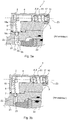
figure 3a est une vue en coupe longitudinale d'un capteur de l'art antérieur présentant un volume interne dans lequel coulisse une pièce mobile, ce volume interne au boitier est ouvert et n'est pas étanche ce qui autorise la migration d'eau de l'extérieur du capteur vers le volume interne ; - la
figure 3b est une vue en coupe du capteur de l'art antérieur illustré à lafigure 3a , on constate la rupture d'un levier d'actionnement de la pièce mobile, cette rupture résulte du fait que la pièce mobile est bloquée par du gel présent dans le boitier alors que le levier immobilisé par le gel contraint par le piston du vérin hydraulique ; - la
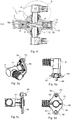
figure 4 est une vue en coupe, selon un plan C-C, du capteur selon l'invention présenté à lafigure 2 ; - la
figure 5a , est une vue en perspective des moyens de détection du capteur selon l'invention alors qu'ils sont assemblés sur une platine, ces moyens de détection et la platine sont identiques à ceux visibles sur lafigure 4 ; - la
figure 5b est une vue de côté des moyens de détection et de la platine illustrés à lafigure 5a ; - la
figure 5c est une vue de face des moyens de détection et de la platine illustrés auxfigures 5a et 5b ; - la
figure 5d est une vue de dessous des moyens de détection et de la platine illustrés auxfigures 5a, 5b et 5c ; - la
figure 6 est une vue en coupe partielle d'un capteur de l'art antérieur où l'on constate la présence d'une rainure formée sur les moyens de détection, cette rainure s'étendant le long d'un passage formé dans le boitier pour permettre l'orientation angulaire de ces moyens de détection par rapport au boitier, un inconvénient de ce capteur est qu'il permet le passage, via la rainure, de fluides vers le volume interne ; - la
figure 7 est une vue en coupe partielle d'un capteur selon l'invention présentant des moyens de détection identiques à ceux du capteur de l'art antérieur, ces moyens de détection comportant notamment une rainure, mais ici les moyens de détection sont assemblés au boitier de manière étanche pour interdire le passage de fluide entre le volume interne et l'extérieur du capteur.
- the
figure 1 is a perspective view of an aircraft undercarriage comprising a hydraulic cylinder extension and retraction of the undercarriage, this cylinder being equipped with a sensor according to the invention to be able to detect a position of displacement of a piston in a hydraulic chamber of the cylinder; - the
figure 2 is a longitudinal sectional view of a portion of the hydraulic cylinder and the sensor used in the undercarriage shown in FIG.figure 1 , this sensor for detecting at least one sliding position of the piston inside the jack; - the
figure 3a is a longitudinal sectional view of a sensor of the prior art having an internal volume in which slides a moving part, this internal volume of the housing is open and is not waterproof which allows the migration of water from the outside the sensor to the internal volume; - the
figure 3b is a sectional view of the sensor of the prior art illustrated in thefigure 3a , there is the rupture of an actuating lever of the moving part, this rupture results from the fact that the moving part is blocked by gel present in the housing while the lever immobilized by the gel constrained by the piston of the hydraulic cylinder ; - the
figure 4 is a sectional view, along a plane CC, of the sensor according to the invention presented in FIG.figure 2 ; - the
figure 5a , is a perspective view of the sensor detection means according to the invention while they are assembled on a plate, these detection means and the plate are identical to those visible on the plate.figure 4 ; - the
figure 5b is a side view of the detection means and the plate shown in FIG.figure 5a ; - the
figure 5c is a front view of the detection means and the plate shown in FIGS.Figures 5a and 5b ; - the
figure 5d is a bottom view of the detection means and the plate shown in FIGS.Figures 5a, 5b and 5c ; - the
figure 6 is a partial sectional view of a sensor of the prior art where it is found the presence of a groove formed on the detection means, this groove extending along a passage formed in the housing to allow the angular orientation of these detection means relative to the housing, a disadvantage of this sensor is that it allows the passage through the groove, fluids to the internal volume; - the
figure 7 is a partial sectional view of a sensor according to the invention having detection means identical to those of the sensor of the prior art, these detection means including a groove, but here the detection means are assembled to the housing in a sealed manner to prevent the passage of fluid between the internal volume and the outside of the sensor.
Comme indiqué précédemment, l'invention concerne un capteur 1 permettant de détecter une position de coulissement d'un piston 22 d'un vérin hydraulique 21.As indicated above, the invention relates to a
Plus particulièrement, l'invention concerne un système 24 tel qu'un atterrisseur d'aéronef équipé d'un vérin hydraulique 21 pour l'extension et/ou la rétraction de l'atterrisseur d'aéronef par rapport à la cellule de l'aéronef. Comme on le voit sur la coupe longitudinale de la
Le capteur 1 est assemblé de manière étanche contre le corps du vérin 21 afin de détecter au moins une position de coulissement du piston 22 à l'intérieur du corps du vérin 21.The
Ce capteur 1 selon l'invention comporte :
un boîtier 2 délimitantun volume interne 3 au boîtier et présentantun passage 31 s'étendant entrece volume interne 3 et une première zone externeZ1 au boitier 2 ;- une pièce mobile 4, formée par exemple par un noyau métallique, située à l'intérieur dudit
volume interne 3 du boîtier pour pouvoir y coulisser ; - des moyens de détection 5 d'un déplacement de ladite pièce mobile 4 par
rapport au boîtier 2, ces moyens de détection 5 comportent une portion de détection 51 qui s'étend dans lepassage 31, entre la première zone externe Z1 et levolume interne 3. Cette portion de détection 51 présente une rainure latérale 52 ouverte vers l'extérieur de la portion de détection 51 et s'étendant entre la première zone externe Z1 et levolume interne 3 au boitier.
- a
housing 2 delimiting aninternal volume 3 to the housing and having apassage 31 extending between thisinternal volume 3 and a first external zone Z1 to thehousing 2; - a moving
part 4, formed for example by a metal core, located inside saidinternal volume 3 of the housing to be able to slide therein; - means 5 for detecting a displacement of said moving
part 4 with respect to thehousing 2, these detection means 5 comprise adetection portion 51 which extends in thepassage 31, between the first external zone Z1 and theinternal volume 3. Thisdetection portion 51 has an openlateral groove 52 to the outside of thedetection portion 51 and extending between the first external zone Z1 and theinternal volume 3 to the housing.
Comme on le voit sur la
Les moyens de détection 5 comportent des composants électroniques placés dans un espace étanche 70 s'étendant à l'intérieur de la portion 51 des moyens de détection 5 qui est placée dans le passage 31 du boîtier. Cet espace étanche 70 permet de protéger les composants électroniques des effets liés à des variations de pression dans le volume interne 3 ou au niveau de la première zone externe Z1.The detection means 5 comprise electronic components placed in a sealed
Ces composants électroniques sont agencés pour générer un signal représentatif d'une position relative de coulissement de la pièce mobile 4 dans le volume interne 3.These electronic components are arranged to generate a signal representative of a relative position of sliding of the moving
Ces composants électroniques peuvent constituer un capteur magnétique ou capacitif détectant la proximité de la pièce 4 par rapport aux composants.These electronic components may constitute a magnetic or capacitive sensor detecting the proximity of the
La transmission de ce signal peut se faire via des moyens filaires 27 reliés aux composants électroniques et passant au travers d'une paroi étanche 71 délimitant l'espace étanche 70. Comme on le voit en particulier sur la
Le passage 31 formé au travers de la paroi du boitier 2 est de forme cylindrique et permet d'introduire la portion 51 des moyens de détection 5 qui est aussi cylindrique.The
Cette portion de détection 51 qui est de forme cylindrique droite s'étend autour et le long d'un axe de symétrie longitudinal X-X. Une rainure rectiligne 52 s'étend parallèlement à cet axe de symétrie longitudinal X-X et le long de la forme cylindrique de la portion de détection 51.This
Cette portion de détection 51 est assemblée de manière étanche à l'intérieur d'une bague annulaire 141, cette bague 141 est elle-même assemblée de manière étanche à l'intérieur du passage 31. Ainsi, lorsqu'ils sont assemblés ensemble, la portion de détection 51, la bague 141 et le boitier 2 forment un ensemble étanche s'opposant au passage de fluide entre le volume interne 3 et la première zone externe Z1.This
Pour cela, la bague annulaire 141 est de forme complémentaire du passage 31 et un joint torique est placé dans une gorge annulaire 142 formée dans le passage 31, à la périphérie du passage. Ce joint torique 142 s'étend autour de la bague 141 de manière à réaliser l'étanchéité tout autour de la bague, entre la bague et le boitier 2. Cette bague et le passage sont ajustés pour permettre d'insérer ou extraire la bague sans endommager, ni le passage 31, ni le joint 142. Ainsi, la bague 141 forme une chemise de guidage en translation de la portion de détection 51 à l'intérieur du passage 31 et par rapport au boitier 2.For this, the
Au moins une portion de longueur de la rainure 52 est remplie d'un matériau d'étanchéité 53 agencé pour s'opposer au passage de fluide entre le volume interne 3 et la première zone externe Z1 via la rainure 52.At least a length portion of the
Ce matériau d'étanchéité 53 peut être un polymère coulé dans la rainure tel que du silicone ou un polymère thermoplastique. On note que la bague et la portion 51 des moyens de détection peuvent être collées entre elles.This sealing
On peut aussi prévoir qu'un joint annulaire s'étende à l'intérieur de la bague pour enserrer la portion 51 et empêcher les fuites entre la bague et la portion 51.It can also be provided that an annular seal extends inside the ring to grip the
Des moyens de fixation 54 sont agencés à l'extérieur du boitier 2 pour assembler les moyens de détection 5 avec le boitier 2.Fastening means 54 are arranged outside the
Les moyens de fixation 54 comportent une platine 59 présentant une perforation filetée 60 dans laquelle est vissée une partie des moyens de détection 5 qui est à l'extérieur du boitier 2. Pour cela, cette perforation 60 présente un filetage femelle complémentaire d'un filetage mâle externe aux moyens de détection 5. Une partie de la rainure 52 qui est à l'extérieur du passage passe au travers de cette platine 59 et s'étend jusqu'à l'extérieur du capteur. La platine 59 est fixée contre une surface externe 61 du boitier 2 qui, dans le cas présent est une surface plane.The fixing means 54 comprise a
La perforation filetée 60 est de dimensions telles qu'elle s'oppose au passage de la bague 141 au travers de la perforation 60. Ainsi, la platine 59 forme une butée axiale s'opposant à la sortie de la bague hors du passage 31. Comme on le voit en particulier, sur les
Les moyens de fixation 54 des moyens de détection 5 présentent aussi une rondelle 55, coaxiale de l'axe X-X et dans laquelle passe une partie des moyens de détection 5 qui est à l'extérieur du boitier 2. Cette rondelle 55 présente des languettes centrale 56 et périphérique 57, la languette centrale 56 pénètre à l'intérieur de la rainure 52 de manière à interdire une rotation relative entre la rondelle 55 et les moyens de détection 5. La languette périphérique 57 pénètre dans un logement complémentaire 58 fixe par rapport au boitier 2 de manière à interdire la rotation relative entre la rondelle 55 et le boitier 2. Cette rondelle 55 est ainsi disposée pour indexer à rotation les moyens de détection 5 par rapport au boitier 2.The fixing means 54 of the detection means 5 also have a
Les moyens de fixation 54 comportent aussi un écrou de serrage 62 de la rondelle 55 contre la platine 59. Cet écrou 62 est vissé sur la partie des moyens de détection 5 qui est à l'extérieur du boitier 2 et dans laquelle s'étend une partie de la rainure 52.The fastening means 54 also comprise a clamping
Le logement 58 dans lequel pénètre la languette périphérique 57 de la rondelle 55 est formé au travers de la platine 59. Ce logement 58 est réalisé à distance de la perforation filetée 60 dans laquelle est vissée la partie des moyens de détection 5 qui est à l'extérieur du boitier 2. Comme la rondelle 55 est placée entre l'écrou 62 et la platine 59 qui sont filetés sur le filetage mâle des moyens de détection 5, on a un effet de positionnement axial des moyens de détection 5 par rapport au boîtier 2. Les languettes de la rondelle ont un effet d'immobilisation en rotation, autour de l'axe X-X, des moyens de détection 5 par rapport au boitier 2.The
Le boitier présente en outre des seconde et troisième ouvertures 7 et 10 s'étendant entre le volume 3 et l'extérieur du boitier.The housing further has second and
Des moyens d'actionnement 6 passent au travers de la seconde ouverture 7 du boîtier 2. Ces moyens d'actionnement 6 sont agencés pour commander le déplacement de ladite pièce mobile 4 depuis une seconde zone externe Z2 au boîtier 2.Actuating means 6 pass through the
Des seconds moyens d'étanchéité 9 sont agencés par rapport au boîtier 2 et aux moyens d'actionnement 6 pour s'opposer au passage de fluide provenant de la seconde zone externe Z2 au boîtier 2 vers ledit volume interne 3 et via la seconde ouverture 7.Second sealing means 9 are arranged relative to the
L'assemblage étanche entre le capteur 1 et le corps du vérin 21 est réalisé :
- de manière que la seconde zone externe Z2 et une portion des moyens d'actionnement 6 soient situés à l'intérieur de la chambre hydraulique 23 du vérin 21 ; et
- de manière qu'un déplacement du
piston 22 dans la chambre hydraulique puisse commander le déplacement des moyens d'actionnement 6 et entrainer le déplacement / coulissement de la pièce mobile 4 dansle volume interne 3 du boitier.
- so that the second outer zone Z2 and a portion of the actuating means 6 are located inside the
hydraulic chamber 23 of thecylinder 21; and - so that a displacement of the
piston 22 in the hydraulic chamber can control the displacement of the actuating means 6 and cause the displacement / sliding of themovable part 4 in theinternal volume 3 of the housing.
Pour cela, les moyens d'actionnement 6 qui passent au travers de la seconde ouverture 7 comportent un levier 18 présentant des première et seconde parties 18a, 18b situées de part et d'autre d'une portion sphérique 18c du levier.For this, the actuating means 6 which pass through the
La première partie de levier 18a se trouve à l'intérieur du volume interne 3 et vient en appui contre la pièce mobile 4. La seconde partie 18b du levier 18 s'étend dans la seconde zone externe Z2 et est agencée pour que le piston 22 puisse venir en contact contre cette seconde partie 18b au moins lorsque ce piston 22 arrive dans une de ses positions de fin de course à l'intérieur du vérin 21.The
Un presse étoupe enserre la portion sphérique 18c du levier afin de lui permettre de pivoter par rapport à ce presse étoupe selon au moins un axe de pivotement perpendiculaire à un axe principal 20 du levier 18. On note que le levier 18 est une pièce s'étendant longitudinalement le long de cet axe principal 20, ce levier étant préférentiellement une pièce de révolution. Ce presse étoupe appartient aux seconds moyens d'étanchéité 9 et réalise une étanchéité contre la portion sphérique 18c du levier 18, tout autour de cette portion sphérique 18c pour interdire le passage de fluide entre la seconde zone Z2 et le volume interne 3.A cable gland grips the
La troisième ouverture 10 est réalisée pour insérer la pièce mobile 4 qui est de forme cylindrique dans le volume interne 3.The
Des troisièmes moyens d'étanchéité 12 comprenant un bouchon fileté 15 sont agencés pour interdire le passage de fluide entre le volume interne 3 et une troisième zone externe Z3 au boitier. Ce bouchon 15 est assemblé par filetage dans la troisième ouverture 10 du volume interne 3.Third sealing means 12 comprising a threaded
Les premiers, deuxièmes et troisièmes moyens d'étanchéité 14, 9, 12 sont dimensionnés pour pouvoir résister à un différentiel de pression d'au moins 300 kPa, cette valeur correspondant à la différence entre une pression régnant à l'intérieur du volume interne et une pression régnant au niveau de la troisième zone externe Z3 au boitier 2.The first, second and third sealing means 14, 9, 12 are dimensioned so as to withstand a pressure differential of at least 300 kPa, this value corresponding to the difference between a pressure prevailing inside the internal volume and a pressure prevailing at the third external zone Z3 to the
On note que cette valeur de 300 kPa correspond approximativement au double du différentiel de pression existant entre une pression atmosphérique mesurée à 0 m d'altitude et une pression atmosphérique mesurée à 12 000 m d'altitude.It is noted that this value of 300 kPa corresponds approximately to twice the differential pressure existing between an atmospheric pressure measured at 0 m altitude and an atmospheric pressure measured at 12 000 m altitude.
Ainsi, les premiers, seconds et troisièmes moyens d'étanchéité résistent aux variations de pression ambiante auxquelles est soumis l'aéronef lors de ses vols.Thus, the first, second and third sealing means resist changes in ambient pressure to which the aircraft is subjected during its flights.
Comme illustré à la
Le système selon l'invention est placé pour détecter le moment où l'atterrisseur est complètement sorti / déployé et où la contrefiche 28 de l'atterrisseur doit être bloquée pour éviter un retour involontaire de l'atterrisseur vers sa position rétractée.The system according to the invention is placed to detect the moment when the undercarriage is completely extended / deployed and where the
Comme illustré à la
Claims (14)
- Sensor (1) comprising:- a casing (2) delimiting an internal volume (3) internal to the casing and having a passage (31) extending between this internal volume and a first external zone (Z1) external to the casing;- a moving part (4) able to move inside the said internal volume (3) of the casing;- detection means (5) for detecting a movement of the said moving part (4) with respect to the casing (2), these detection means (5) comprising a detection portion (51) extending in the passage (31), between the said first external zone (Z1) external to the casing and the said internal volume (3) internal to the casing, this detection portion (51) also having a groove (52) open to the outside of the detection portion (51) for orienting the portion (51) of the detection means (5) relative to the casing (2), this groove (52) extending between the said first external zone (Z1) external to the casing and the said internal volume (3) internal to the casing, characterized in that it comprises first sealing means (14) positioned around the detection portion (51) and placed inside the passage (31), these first sealing means (14) being arranged in such a way as to prevent fluid from passing between the internal volume (3) and the first external zone (Z1) external to the casing (2) via said groove (52).
- Sensor (1) according to claim 1, in which at least one portion of the length of the groove (52) is filled with a sealant (53) arranged to oppose the said passage of fluid between the internal volume (3) and the first external zone (Z1) external to the casing via the said groove (52).
- Sensor according to Claim 2, in which these first sealing means (14) comprise an annular ring (141) assembled in a sealed manner inside the passage (31) to form a guide sleeve guiding the translational movement of the detection portion (51) inside the passage (31) and with respect to the casing (2), the detection portion (51) being assembled in a sealed manner inside the ring (141), the ring (141) assembled inside the passage (31) and the detection portion (51) assembled inside the ring (141) forming a sealed assembly that opposes the passage of fluid between the internal volume (3) and the first external zone (Z1).
- Sensor (1) according to Claim 3, in which these first sealing means (14) comprise an annular seal (142) positioned around the ring in such a way as to oppose the passage of fluid, around the outside of the ring (141), between the internal volume (3) and the first external zone (Z1).
- Sensor according to any one of the preceding claims, in which the detection portion (51) is of right cylindrical shape and extends around and along a longitudinal axis of symmetry (X-X), the said groove (52) being rectilinear and extending parallel to this longitudinal axis of symmetry (X-X).
- Sensor (1) according to any one of the preceding claims, further comprising securing means (54) arranged on the outside of the casing (2) so as to assemble the detecting means (5) with the casing (2), these securing means (54) having a washer (55) through which washer there passes a part of the detection means (5) which is outside the casing (2) and along which part of the said groove (52) extends, this washer (55) having central (56) and peripheral (57) tabs, the central tab (56) entering the groove (52) so as to prevent relative rotation between the washer (55) and the detection means (5), the peripheral tab (57) entering a complementary housing (58) that is fixed with respect to the casing (2) so as to prevent relative rotation between the washer (55) and the casing (2), this washer (55) being positioned in such a way as to index in terms of rotation the detection means (5) with respect to the casing (2).
- Sensor (1) according to Claim 6, in which the securing means (54) comprise a mounting plate (59) having a threaded hole (60) into which is screwed that part of the detection means (5) that is outside the casing (2) and along which part of the said groove (52) extends, this mounting plate (59) also being secured against an external surface (61) of the casing (2).
- Sensor (1) according to Claims 6 and 7, in which the securing means (54) comprise a nut (62) for clamping the washer (55) against the mounting plate (59), this nut (62) being screwed onto that part of the detection means (5) that is outside the casing (2) and along which part of the groove (52) extends.
- Sensor according to any one of the preceding claims, further comprising:- actuating means (6) passing through a second opening (7) formed in the casing (2), these actuating means (6) being arranged in such a way as to control the movement of the said moving part (4) situated inside the said internal volume (3) from a second external zone (Z2) external to the casing (2);- second sealing means (9) arranged with respect to the casing (2) and with respect to the actuating means (6) in such a way as to oppose the passage of fluid from the second external zone (Z2) external to the casing (2) towards the said internal volume (3) of the casing, via the said second opening (7) of the casing,- a third opening (10) extending between the said internal volume (3) of the casing (2) and a third external zone (Z3) external to the casing and which is distant from the said first and second external zones (Z1, Z2) of the casing; and- third sealing means (12) arranged in such a way as to oppose the passage of fluid between the said internal volume (3) of the casing (2) and the third external zone (Z3) via the said third opening (10).
- Sensor according to at least one of claims 1 to 9, in which the detection means (5) comprise electronic components which are situated away from the said internal volume (3) and extend into the said passage (31) of the casing.
- Sensor according to claim 9, in which the third sealing means (12) comprise a plug (15) assembled in the third opening (10) of the internal volume (3), this plug (15) being assembled with the casing (2) via a screw thread.
- Sensor according to the preceding claim, in which the moving part (4) is able to slide inside the said internal volume (3) of the casing and a return spring (17) applies to this moving part (4) an elastic return force returning it towards a first position, this return spring (17) being compressed between the plug (15) and the moving part (4) against each of which it rests.
- System comprising a sensor according to any one of the preceding claims, combined with claim 9, this system further comprising a hydraulic actuating cylinder (21) comprising a piston (22) and a hydraulic chamber (23) in which this piston (22) slides, the said second external zone (Z2) external to the casing (2) and a portion of the actuating means (6) being situated inside the hydraulic chamber (23) of the actuating cylinder (21) so that a movement of the piston (22) in the hydraulic chamber (23) can control the movement of the actuating means (6) and cause the moving part (4) to move inside the internal volume (3) of the casing (2) of the sensor (1).
- System according to Claim 13, in which the hydraulic actuating cylinder (21) is a hydraulic actuating cylinder that deploys and retracts an aircraft landing gear.
Applications Claiming Priority (1)
| Application Number | Priority Date | Filing Date | Title |
|---|---|---|---|
| FR1458926A FR3026178B1 (en) | 2014-09-22 | 2014-09-22 | AIRCRAFT PROXIMITY SENSOR HAVING A SPECIAL SEALED ASSEMBLY |
Publications (2)
| Publication Number | Publication Date |
|---|---|
| EP2998709A1 EP2998709A1 (en) | 2016-03-23 |
| EP2998709B1 true EP2998709B1 (en) | 2017-11-01 |
Family
ID=51987340
Family Applications (1)
| Application Number | Title | Priority Date | Filing Date |
|---|---|---|---|
| EP15183769.7A Active EP2998709B1 (en) | 2014-09-22 | 2015-09-03 | Proximity sensor for aircraft, provided with a special sealed assembly |
Country Status (4)
| Country | Link |
|---|---|
| US (1) | US9784600B2 (en) |
| EP (1) | EP2998709B1 (en) |
| CA (1) | CA2905054C (en) |
| FR (1) | FR3026178B1 (en) |
Cited By (1)
| Publication number | Priority date | Publication date | Assignee | Title |
|---|---|---|---|---|
| DE202022100277U1 (en) | 2022-01-19 | 2023-04-21 | Liebherr-Aerospace Lindenberg Gmbh | lock detection device |
Families Citing this family (1)
| Publication number | Priority date | Publication date | Assignee | Title |
|---|---|---|---|---|
| CN113049019B (en) * | 2019-12-26 | 2022-09-20 | 中国航空工业集团公司西安飞机设计研究所 | Circumferential relative motion test bed for magnetic induction type proximity sensor |
Family Cites Families (4)
| Publication number | Priority date | Publication date | Assignee | Title |
|---|---|---|---|---|
| EP1904809A1 (en) * | 2005-07-20 | 2008-04-02 | The Timken Company | Sensor assembly |
| DE102005060676B4 (en) * | 2005-12-19 | 2021-01-21 | Asm Automation Sensorik Messtechnik Gmbh | Rod-type position sensor and replacement method |
| DE102006043291A1 (en) * | 2006-09-14 | 2008-03-27 | Zf Friedrichshafen Ag | Non-contact angle sensor |
| DE102007037759A1 (en) * | 2007-08-10 | 2009-02-12 | Schaeffler Kg | Device for determining a switching position of a mechanical system |
-
2014
- 2014-09-22 FR FR1458926A patent/FR3026178B1/en active Active
-
2015
- 2015-09-03 EP EP15183769.7A patent/EP2998709B1/en active Active
- 2015-09-10 US US14/849,893 patent/US9784600B2/en active Active
- 2015-09-18 CA CA2905054A patent/CA2905054C/en active Active
Non-Patent Citations (1)
| Title |
|---|
| None * |
Cited By (1)
| Publication number | Priority date | Publication date | Assignee | Title |
|---|---|---|---|---|
| DE202022100277U1 (en) | 2022-01-19 | 2023-04-21 | Liebherr-Aerospace Lindenberg Gmbh | lock detection device |
Also Published As
| Publication number | Publication date |
|---|---|
| EP2998709A1 (en) | 2016-03-23 |
| CA2905054A1 (en) | 2016-03-22 |
| US9784600B2 (en) | 2017-10-10 |
| US20160084681A1 (en) | 2016-03-24 |
| FR3026178A1 (en) | 2016-03-25 |
| CA2905054C (en) | 2018-01-02 |
| FR3026178B1 (en) | 2018-05-18 |
Similar Documents
| Publication | Publication Date | Title |
|---|---|---|
| EP2440806B1 (en) | Shock absorber and landing gear provided with such a shock absorber | |
| EP3074671B1 (en) | Isolation valve having a vacuum chamber | |
| EP2998709B1 (en) | Proximity sensor for aircraft, provided with a special sealed assembly | |
| EP3071858A2 (en) | Sliding caliper disc brake having evacuation of air between pins and bores | |
| US20180106312A1 (en) | Bleeding valve, a hydraulic fitting and a venting assembly for a bicycle hydraulic braking system | |
| EP3092368A1 (en) | Insulation device for a well | |
| EP3785803B1 (en) | Valve and system for applying a coating product comprising such a valve | |
| EP3051150B1 (en) | Proximity sensor for aircraft provided with a hydraulic fuse | |
| FR3094444A1 (en) | Rotary joint device configured to equip a fluid exploitation installation, in particular on an offshore platform | |
| FR3016007A1 (en) | EMERGENCY ACTUATING DEVICE, PARTICULARLY FOR USE BY AN AIRCRAFT OPENER | |
| EP2570326B1 (en) | Liquid discharge and air exchange device for the steering of a motor vehicle | |
| EP3017210B1 (en) | Braking device using a piston with total recoil function | |
| FR3100302A1 (en) | Valve, coating product application system comprising such a valve | |
| CA3154857C (en) | Anti-propagation exhaust device for aircraft lithium-ion batteries | |
| FR3064595A1 (en) | DEPLOYABLE ASSEMBLY, AIRCRAFT AND DEPLOYMENT METHOD THEREOF | |
| FR2970055A1 (en) | Sealing device e.g. bidirectional mechanical sealing device, for e.g. sampling valve in liquid pipe, has joints to control deformation of monoblock assembly formed by joints and seat when piston is supported on seat in unbalanced manner | |
| EP3027884B1 (en) | Integrated arrangement of a high-pressure valve and an injection ramp | |
| FR3003327A1 (en) | SHUT OFF DEVICE OF A HYDRAULIC SYSTEM HYDRAULIC SYSTEM AND AIRCRAFT | |
| EP3237723B1 (en) | Device for insulating a portion of a well or a pipeline, and control means implemented in such an insulation device | |
| FR3013320A1 (en) | SUBMARINE ENGINE EQUIPPED WITH AT LEAST ONE BUOY PROVIDED WITH A FUNCTIONAL ORGAN | |
| FR3082958A1 (en) | PRESSURE REGULATOR FOR COMMON RAMP AND COMMON RAMP EQUIPPED WITH SUCH A PRESSURE REGULATOR | |
| EP1069354A1 (en) | Back-flow preventer | |
| FR3115336A1 (en) | Pump for cryogenic fluid | |
| EP2166233A1 (en) | Gradual action jack | |
| WO2015044586A1 (en) | Hydraulic connection device and fluid transfer system using said device |
Legal Events
| Date | Code | Title | Description |
|---|---|---|---|
| PUAI | Public reference made under article 153(3) epc to a published international application that has entered the european phase |
Free format text: ORIGINAL CODE: 0009012 |
|
| AK | Designated contracting states |
Kind code of ref document: A1 Designated state(s): AL AT BE BG CH CY CZ DE DK EE ES FI FR GB GR HR HU IE IS IT LI LT LU LV MC MK MT NL NO PL PT RO RS SE SI SK SM TR |
|
| AX | Request for extension of the european patent |
Extension state: BA ME |
|
| 17P | Request for examination filed |
Effective date: 20160826 |
|
| RBV | Designated contracting states (corrected) |
Designated state(s): AL AT BE BG CH CY CZ DE DK EE ES FI FR GB GR HR HU IE IS IT LI LT LU LV MC MK MT NL NO PL PT RO RS SE SI SK SM TR |
|
| RAP1 | Party data changed (applicant data changed or rights of an application transferred) |
Owner name: SAFRAN LANDING SYSTEMS |
|
| RAP1 | Party data changed (applicant data changed or rights of an application transferred) |
Owner name: SAFRAN LANDING SYSTEMS |
|
| GRAP | Despatch of communication of intention to grant a patent |
Free format text: ORIGINAL CODE: EPIDOSNIGR1 |
|
| STAA | Information on the status of an ep patent application or granted ep patent |
Free format text: STATUS: GRANT OF PATENT IS INTENDED |
|
| INTG | Intention to grant announced |
Effective date: 20170509 |
|
| GRAS | Grant fee paid |
Free format text: ORIGINAL CODE: EPIDOSNIGR3 |
|
| GRAA | (expected) grant |
Free format text: ORIGINAL CODE: 0009210 |
|
| STAA | Information on the status of an ep patent application or granted ep patent |
Free format text: STATUS: THE PATENT HAS BEEN GRANTED |
|
| AK | Designated contracting states |
Kind code of ref document: B1 Designated state(s): AL AT BE BG CH CY CZ DE DK EE ES FI FR GB GR HR HU IE IS IT LI LT LU LV MC MK MT NL NO PL PT RO RS SE SI SK SM TR |
|
| REG | Reference to a national code |
Ref country code: GB Ref legal event code: FG4D Free format text: NOT ENGLISH |
|
| REG | Reference to a national code |
Ref country code: CH Ref legal event code: EP Ref country code: AT Ref legal event code: REF Ref document number: 942497 Country of ref document: AT Kind code of ref document: T Effective date: 20171115 |
|
| REG | Reference to a national code |
Ref country code: IE Ref legal event code: FG4D Free format text: LANGUAGE OF EP DOCUMENT: FRENCH |
|
| REG | Reference to a national code |
Ref country code: DE Ref legal event code: R096 Ref document number: 602015005700 Country of ref document: DE |
|
| REG | Reference to a national code |
Ref country code: NL Ref legal event code: MP Effective date: 20171101 |
|
| REG | Reference to a national code |
Ref country code: LT Ref legal event code: MG4D |
|
| REG | Reference to a national code |
Ref country code: AT Ref legal event code: MK05 Ref document number: 942497 Country of ref document: AT Kind code of ref document: T Effective date: 20171101 |
|
| PG25 | Lapsed in a contracting state [announced via postgrant information from national office to epo] |
Ref country code: SE Free format text: LAPSE BECAUSE OF FAILURE TO SUBMIT A TRANSLATION OF THE DESCRIPTION OR TO PAY THE FEE WITHIN THE PRESCRIBED TIME-LIMIT Effective date: 20171101 Ref country code: NL Free format text: LAPSE BECAUSE OF FAILURE TO SUBMIT A TRANSLATION OF THE DESCRIPTION OR TO PAY THE FEE WITHIN THE PRESCRIBED TIME-LIMIT Effective date: 20171101 Ref country code: FI Free format text: LAPSE BECAUSE OF FAILURE TO SUBMIT A TRANSLATION OF THE DESCRIPTION OR TO PAY THE FEE WITHIN THE PRESCRIBED TIME-LIMIT Effective date: 20171101 Ref country code: NO Free format text: LAPSE BECAUSE OF FAILURE TO SUBMIT A TRANSLATION OF THE DESCRIPTION OR TO PAY THE FEE WITHIN THE PRESCRIBED TIME-LIMIT Effective date: 20180201 Ref country code: ES Free format text: LAPSE BECAUSE OF FAILURE TO SUBMIT A TRANSLATION OF THE DESCRIPTION OR TO PAY THE FEE WITHIN THE PRESCRIBED TIME-LIMIT Effective date: 20171101 Ref country code: LT Free format text: LAPSE BECAUSE OF FAILURE TO SUBMIT A TRANSLATION OF THE DESCRIPTION OR TO PAY THE FEE WITHIN THE PRESCRIBED TIME-LIMIT Effective date: 20171101 |
|
| PG25 | Lapsed in a contracting state [announced via postgrant information from national office to epo] |
Ref country code: AT Free format text: LAPSE BECAUSE OF FAILURE TO SUBMIT A TRANSLATION OF THE DESCRIPTION OR TO PAY THE FEE WITHIN THE PRESCRIBED TIME-LIMIT Effective date: 20171101 Ref country code: GR Free format text: LAPSE BECAUSE OF FAILURE TO SUBMIT A TRANSLATION OF THE DESCRIPTION OR TO PAY THE FEE WITHIN THE PRESCRIBED TIME-LIMIT Effective date: 20180202 Ref country code: RS Free format text: LAPSE BECAUSE OF FAILURE TO SUBMIT A TRANSLATION OF THE DESCRIPTION OR TO PAY THE FEE WITHIN THE PRESCRIBED TIME-LIMIT Effective date: 20171101 Ref country code: BG Free format text: LAPSE BECAUSE OF FAILURE TO SUBMIT A TRANSLATION OF THE DESCRIPTION OR TO PAY THE FEE WITHIN THE PRESCRIBED TIME-LIMIT Effective date: 20180201 Ref country code: LV Free format text: LAPSE BECAUSE OF FAILURE TO SUBMIT A TRANSLATION OF THE DESCRIPTION OR TO PAY THE FEE WITHIN THE PRESCRIBED TIME-LIMIT Effective date: 20171101 Ref country code: HR Free format text: LAPSE BECAUSE OF FAILURE TO SUBMIT A TRANSLATION OF THE DESCRIPTION OR TO PAY THE FEE WITHIN THE PRESCRIBED TIME-LIMIT Effective date: 20171101 Ref country code: IS Free format text: LAPSE BECAUSE OF FAILURE TO SUBMIT A TRANSLATION OF THE DESCRIPTION OR TO PAY THE FEE WITHIN THE PRESCRIBED TIME-LIMIT Effective date: 20180301 |
|
| PG25 | Lapsed in a contracting state [announced via postgrant information from national office to epo] |
Ref country code: DK Free format text: LAPSE BECAUSE OF FAILURE TO SUBMIT A TRANSLATION OF THE DESCRIPTION OR TO PAY THE FEE WITHIN THE PRESCRIBED TIME-LIMIT Effective date: 20171101 Ref country code: SK Free format text: LAPSE BECAUSE OF FAILURE TO SUBMIT A TRANSLATION OF THE DESCRIPTION OR TO PAY THE FEE WITHIN THE PRESCRIBED TIME-LIMIT Effective date: 20171101 Ref country code: CZ Free format text: LAPSE BECAUSE OF FAILURE TO SUBMIT A TRANSLATION OF THE DESCRIPTION OR TO PAY THE FEE WITHIN THE PRESCRIBED TIME-LIMIT Effective date: 20171101 Ref country code: EE Free format text: LAPSE BECAUSE OF FAILURE TO SUBMIT A TRANSLATION OF THE DESCRIPTION OR TO PAY THE FEE WITHIN THE PRESCRIBED TIME-LIMIT Effective date: 20171101 Ref country code: CY Free format text: LAPSE BECAUSE OF FAILURE TO SUBMIT A TRANSLATION OF THE DESCRIPTION OR TO PAY THE FEE WITHIN THE PRESCRIBED TIME-LIMIT Effective date: 20171101 |
|
| REG | Reference to a national code |
Ref country code: DE Ref legal event code: R097 Ref document number: 602015005700 Country of ref document: DE |
|
| REG | Reference to a national code |
Ref country code: FR Ref legal event code: PLFP Year of fee payment: 4 |
|
| PG25 | Lapsed in a contracting state [announced via postgrant information from national office to epo] |
Ref country code: PL Free format text: LAPSE BECAUSE OF FAILURE TO SUBMIT A TRANSLATION OF THE DESCRIPTION OR TO PAY THE FEE WITHIN THE PRESCRIBED TIME-LIMIT Effective date: 20171101 Ref country code: RO Free format text: LAPSE BECAUSE OF FAILURE TO SUBMIT A TRANSLATION OF THE DESCRIPTION OR TO PAY THE FEE WITHIN THE PRESCRIBED TIME-LIMIT Effective date: 20171101 Ref country code: IT Free format text: LAPSE BECAUSE OF FAILURE TO SUBMIT A TRANSLATION OF THE DESCRIPTION OR TO PAY THE FEE WITHIN THE PRESCRIBED TIME-LIMIT Effective date: 20171101 Ref country code: SM Free format text: LAPSE BECAUSE OF FAILURE TO SUBMIT A TRANSLATION OF THE DESCRIPTION OR TO PAY THE FEE WITHIN THE PRESCRIBED TIME-LIMIT Effective date: 20171101 |
|
| PLBE | No opposition filed within time limit |
Free format text: ORIGINAL CODE: 0009261 |
|
| STAA | Information on the status of an ep patent application or granted ep patent |
Free format text: STATUS: NO OPPOSITION FILED WITHIN TIME LIMIT |
|
| PG25 | Lapsed in a contracting state [announced via postgrant information from national office to epo] |
Ref country code: MT Free format text: LAPSE BECAUSE OF FAILURE TO SUBMIT A TRANSLATION OF THE DESCRIPTION OR TO PAY THE FEE WITHIN THE PRESCRIBED TIME-LIMIT Effective date: 20171101 |
|
| 26N | No opposition filed |
Effective date: 20180802 |
|
| PG25 | Lapsed in a contracting state [announced via postgrant information from national office to epo] |
Ref country code: SI Free format text: LAPSE BECAUSE OF FAILURE TO SUBMIT A TRANSLATION OF THE DESCRIPTION OR TO PAY THE FEE WITHIN THE PRESCRIBED TIME-LIMIT Effective date: 20171101 |
|
| PG25 | Lapsed in a contracting state [announced via postgrant information from national office to epo] |
Ref country code: MC Free format text: LAPSE BECAUSE OF FAILURE TO SUBMIT A TRANSLATION OF THE DESCRIPTION OR TO PAY THE FEE WITHIN THE PRESCRIBED TIME-LIMIT Effective date: 20171101 |
|
| REG | Reference to a national code |
Ref country code: CH Ref legal event code: PL |
|
| REG | Reference to a national code |
Ref country code: BE Ref legal event code: MM Effective date: 20180930 |
|
| REG | Reference to a national code |
Ref country code: IE Ref legal event code: MM4A |
|
| PG25 | Lapsed in a contracting state [announced via postgrant information from national office to epo] |
Ref country code: LU Free format text: LAPSE BECAUSE OF NON-PAYMENT OF DUE FEES Effective date: 20180903 |
|
| PG25 | Lapsed in a contracting state [announced via postgrant information from national office to epo] |
Ref country code: IE Free format text: LAPSE BECAUSE OF NON-PAYMENT OF DUE FEES Effective date: 20180903 |
|
| PG25 | Lapsed in a contracting state [announced via postgrant information from national office to epo] |
Ref country code: LI Free format text: LAPSE BECAUSE OF NON-PAYMENT OF DUE FEES Effective date: 20180930 Ref country code: CH Free format text: LAPSE BECAUSE OF NON-PAYMENT OF DUE FEES Effective date: 20180930 Ref country code: BE Free format text: LAPSE BECAUSE OF NON-PAYMENT OF DUE FEES Effective date: 20180930 |
|
| PG25 | Lapsed in a contracting state [announced via postgrant information from national office to epo] |
Ref country code: TR Free format text: LAPSE BECAUSE OF FAILURE TO SUBMIT A TRANSLATION OF THE DESCRIPTION OR TO PAY THE FEE WITHIN THE PRESCRIBED TIME-LIMIT Effective date: 20171101 |
|
| PG25 | Lapsed in a contracting state [announced via postgrant information from national office to epo] |
Ref country code: PT Free format text: LAPSE BECAUSE OF FAILURE TO SUBMIT A TRANSLATION OF THE DESCRIPTION OR TO PAY THE FEE WITHIN THE PRESCRIBED TIME-LIMIT Effective date: 20171101 |
|
| PG25 | Lapsed in a contracting state [announced via postgrant information from national office to epo] |
Ref country code: MK Free format text: LAPSE BECAUSE OF NON-PAYMENT OF DUE FEES Effective date: 20171101 Ref country code: HU Free format text: LAPSE BECAUSE OF FAILURE TO SUBMIT A TRANSLATION OF THE DESCRIPTION OR TO PAY THE FEE WITHIN THE PRESCRIBED TIME-LIMIT; INVALID AB INITIO Effective date: 20150903 |
|
| PG25 | Lapsed in a contracting state [announced via postgrant information from national office to epo] |
Ref country code: AL Free format text: LAPSE BECAUSE OF FAILURE TO SUBMIT A TRANSLATION OF THE DESCRIPTION OR TO PAY THE FEE WITHIN THE PRESCRIBED TIME-LIMIT Effective date: 20171101 |
|
| PGFP | Annual fee paid to national office [announced via postgrant information from national office to epo] |
Ref country code: GB Payment date: 20230823 Year of fee payment: 9 |
|
| PGFP | Annual fee paid to national office [announced via postgrant information from national office to epo] |
Ref country code: FR Payment date: 20230822 Year of fee payment: 9 Ref country code: DE Payment date: 20230822 Year of fee payment: 9 |