EP2998709B1 - Näherungssensor für luftfahrzeug, das mit einer besonderen wasserdichten anordnung ausgestattet ist - Google Patents
Näherungssensor für luftfahrzeug, das mit einer besonderen wasserdichten anordnung ausgestattet ist Download PDFInfo
- Publication number
- EP2998709B1 EP2998709B1 EP15183769.7A EP15183769A EP2998709B1 EP 2998709 B1 EP2998709 B1 EP 2998709B1 EP 15183769 A EP15183769 A EP 15183769A EP 2998709 B1 EP2998709 B1 EP 2998709B1
- Authority
- EP
- European Patent Office
- Prior art keywords
- casing
- internal volume
- passage
- external
- sensor
- Prior art date
- Legal status (The legal status is an assumption and is not a legal conclusion. Google has not performed a legal analysis and makes no representation as to the accuracy of the status listed.)
- Active
Links
- 238000001514 detection method Methods 0.000 claims description 83
- 238000007789 sealing Methods 0.000 claims description 23
- 239000012530 fluid Substances 0.000 claims description 22
- 230000033001 locomotion Effects 0.000 claims description 7
- 230000000295 complement effect Effects 0.000 claims description 6
- 230000002093 peripheral effect Effects 0.000 claims description 5
- 239000000565 sealant Substances 0.000 claims 1
- 238000006073 displacement reaction Methods 0.000 description 13
- XLYOFNOQVPJJNP-UHFFFAOYSA-N water Chemical compound O XLYOFNOQVPJJNP-UHFFFAOYSA-N 0.000 description 8
- BASFCYQUMIYNBI-UHFFFAOYSA-N platinum Chemical compound [Pt] BASFCYQUMIYNBI-UHFFFAOYSA-N 0.000 description 5
- 239000003566 sealing material Substances 0.000 description 5
- 210000002105 tongue Anatomy 0.000 description 4
- 230000000903 blocking effect Effects 0.000 description 2
- 230000000694 effects Effects 0.000 description 2
- 210000004907 gland Anatomy 0.000 description 2
- 230000007257 malfunction Effects 0.000 description 2
- 238000013508 migration Methods 0.000 description 2
- 230000005012 migration Effects 0.000 description 2
- 238000013519 translation Methods 0.000 description 2
- 240000008042 Zea mays Species 0.000 description 1
- 230000005540 biological transmission Effects 0.000 description 1
- 230000015572 biosynthetic process Effects 0.000 description 1
- 238000004891 communication Methods 0.000 description 1
- 230000010006 flight Effects 0.000 description 1
- 230000003100 immobilizing effect Effects 0.000 description 1
- 238000012423 maintenance Methods 0.000 description 1
- 239000002184 metal Substances 0.000 description 1
- 238000000034 method Methods 0.000 description 1
- 230000000149 penetrating effect Effects 0.000 description 1
- 229920000642 polymer Polymers 0.000 description 1
- 229920001296 polysiloxane Polymers 0.000 description 1
- 230000002035 prolonged effect Effects 0.000 description 1
- 229920001169 thermoplastic Polymers 0.000 description 1
Images


Classifications
-
- G—PHYSICS
- G01—MEASURING; TESTING
- G01D—MEASURING NOT SPECIALLY ADAPTED FOR A SPECIFIC VARIABLE; ARRANGEMENTS FOR MEASURING TWO OR MORE VARIABLES NOT COVERED IN A SINGLE OTHER SUBCLASS; TARIFF METERING APPARATUS; MEASURING OR TESTING NOT OTHERWISE PROVIDED FOR
- G01D11/00—Component parts of measuring arrangements not specially adapted for a specific variable
- G01D11/24—Housings ; Casings for instruments
-
- B—PERFORMING OPERATIONS; TRANSPORTING
- B64—AIRCRAFT; AVIATION; COSMONAUTICS
- B64C—AEROPLANES; HELICOPTERS
- B64C25/00—Alighting gear
- B64C25/001—Devices not provided for in the groups B64C25/02 - B64C25/68
-
- G—PHYSICS
- G01—MEASURING; TESTING
- G01D—MEASURING NOT SPECIALLY ADAPTED FOR A SPECIFIC VARIABLE; ARRANGEMENTS FOR MEASURING TWO OR MORE VARIABLES NOT COVERED IN A SINGLE OTHER SUBCLASS; TARIFF METERING APPARATUS; MEASURING OR TESTING NOT OTHERWISE PROVIDED FOR
- G01D11/00—Component parts of measuring arrangements not specially adapted for a specific variable
- G01D11/24—Housings ; Casings for instruments
- G01D11/245—Housings for sensors
-
- G—PHYSICS
- G01—MEASURING; TESTING
- G01D—MEASURING NOT SPECIALLY ADAPTED FOR A SPECIFIC VARIABLE; ARRANGEMENTS FOR MEASURING TWO OR MORE VARIABLES NOT COVERED IN A SINGLE OTHER SUBCLASS; TARIFF METERING APPARATUS; MEASURING OR TESTING NOT OTHERWISE PROVIDED FOR
- G01D11/00—Component parts of measuring arrangements not specially adapted for a specific variable
- G01D11/30—Supports specially adapted for an instrument; Supports specially adapted for a set of instruments
-
- G—PHYSICS
- G01—MEASURING; TESTING
- G01D—MEASURING NOT SPECIALLY ADAPTED FOR A SPECIFIC VARIABLE; ARRANGEMENTS FOR MEASURING TWO OR MORE VARIABLES NOT COVERED IN A SINGLE OTHER SUBCLASS; TARIFF METERING APPARATUS; MEASURING OR TESTING NOT OTHERWISE PROVIDED FOR
- G01D5/00—Mechanical means for transferring the output of a sensing member; Means for converting the output of a sensing member to another variable where the form or nature of the sensing member does not constrain the means for converting; Transducers not specially adapted for a specific variable
- G01D5/12—Mechanical means for transferring the output of a sensing member; Means for converting the output of a sensing member to another variable where the form or nature of the sensing member does not constrain the means for converting; Transducers not specially adapted for a specific variable using electric or magnetic means
Definitions
- the invention relates to a sensor and in particular to a system comprising a jack and a sensor for detecting a position of a piston of the jack.
- the portion of the detection detection means that is disposed in the housing passage has an open groove outwardly. This groove formed on the detection means allows an angular positioning of the detection portion vis-à-vis the housing.
- Such a sensor may have malfunctions in cold conditions because the cold / ice can oppose the sliding of the moving part in the internal volume.
- the documents DE102005060676 and WO2007 / 012072 disclose known sensors having a sealed passage.
- the object of the invention is to obtain a sensor capable of limiting the risk of malfunctioning when it is subjected to low temperatures.
- a sensor of the predefined type and essentially characterized in that it comprises first sealing means arranged around the detection portion and placed inside the passage these first sealing means being arranged to prohibit the passage of fluid between the internal volume and the first zone external to the housing via said groove.
- the sealing means prohibit the passage of fluid via the groove, it limits the risk of having a moisture inlet to the internal volume and therefore, it limits the risk of blocking, by ice, the room mobile in this internal volume.
- the invention is particularly useful in fields such as aeronautics where sensors must be standardized and certified before they can be used. Thanks to the invention, while providing an additional sealing function between detection means and housing, can be used detection means already standardized and having an orientation groove to guide the detection means relative to the housing. This avoids the need to develop new detection means without groove which would involve engaging in a heavy standardization process.
- the sensor according to the invention is particularly adapted to be integrated on an aircraft undercarriage for detecting a position of a piston of a jack of the undercarriage. Indeed, during its displacement, the aircraft is subjected to important variations of pressure, temperature and humidity which tends to favor the formation of gel in spaces containing water or water vapor. By limiting the fluid passage, via the groove, to the internal volume of the sensor, it limits the risk of malfunction at low temperatures by blocking the moving part.
- the first sealing means are adapted to guarantee a leaktight passage of fluids as long as the differential pressure between the internal volume and the first external zone does not exceed 300 kPa.
- the value of 300 kPa is twice the value of 150 kPa, which is the maximum pressure differential between an atmospheric pressure measured at 0 m altitude and an atmospheric pressure measured at 12 000 m altitude.
- At least a length portion of the groove is filled with a sealing material arranged to oppose said fluid passage between the internal volume and the first external zone to the housing via said groove.
- the first sealing means comprise an annular ring sealingly assembled inside the passageway to form a guiding jacket in translation of the detection portion inside. of the passage and in relation to the case.
- the detection portion is sealingly assembled inside the ring and the ring assembled inside the passage, the detection portion assembled inside the ring form a sealed assembly opposing the passage of fluid between the internal volume and the first external zone.
- This embodiment makes it possible to have a interface between the detection portion penetrating the passage of the housing and the inner surface of the housing. This interface is useful for example to prevent the sealing material present in the groove comes into contact against a surface of the housing during assembly or disassembly of the detection means.
- the first sealing means comprise an annular seal, such as an O-ring, arranged around the ring and arranged to oppose the passage of fluid, by the outside of the ring, between the internal volume and the first external zone.
- annular seal facilitates maintenance operations of the sensor by allowing the assembly and disassembly of the ring vis-à-vis the passage.
- the annular seal is an O-ring placed in an annular groove formed around the passage and opening into this passage of the housing.
- the detection means comprise electronic components such as a transistor and / or an amplifier and / or an inductor that can be damaged in the event of prolonged contact with ice. or water. To protect them, these electronic components are placed in a sealed space located inside the portion of the detection means which is placed in the passage of the housing.
- the invention also relates to a system comprising a sensor according to the preceding embodiment of the invention, this system further comprising a hydraulic cylinder comprising a piston and a hydraulic chamber in which this piston slides, said second zone external to the housing and a portion of the actuating means being located inside the hydraulic chamber of the jack so that a displacement of the piston in the hydraulic chamber can control the displacement of the actuating means and cause the displacement of the moving part in the internal volume of the sensor housing.
- the displacement detection means of the moving part are in communication with the internal volume of the sensor housing to detect the displacement of this moving part.
- the internal volume of the housing and the hydraulic chamber are hydraulically isolated from each other by the second sealing means which prevent the detection means from being subjected to the high hydraulic pressures exerted in the cylinder chamber.
- the actuating means which extend in part in the chamber of the hydraulic cylinder can control the movement of the moving part in the housing according to the position of the piston in the hydraulic cylinder.
- the senor according to the invention can be used to determine the positioning of a piston in a hydraulic cylinder chamber without exposing the detection means to the high pressures of the hydraulic chamber.
- the invention relates to a sensor 1 for detecting a sliding position of a piston 22 of a hydraulic cylinder 21.
- the invention relates to a system 24 such as an aircraft undercarriage equipped with a hydraulic cylinder 21 for extending and / or retracting the aircraft undercarriage relative to the aircraft cell.
- a system 24 such as an aircraft undercarriage equipped with a hydraulic cylinder 21 for extending and / or retracting the aircraft undercarriage relative to the aircraft cell.
- this jack 21 has a piston 22 and a hydraulic chamber 23 in which this piston 22 slides.
- the sensor 1 is assembled in a sealed manner against the body of the jack 21 in order to detect at least one sliding position of the piston 22 inside the body of the jack 21.
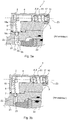
- the senor 1 comprises first sealing means 14 disposed around the detection portion 51 and placed inside the passage 31. These first sealing means 14 are arranged to prohibit the passage of fluid between the internal volume 3 and the first external zone Z1 via said groove 52.
- the detection means 5 comprise electronic components placed in a sealed space 70 extending inside the portion 51 of the detection means 5 which is placed in the passage 31 of the housing.
- This sealed space 70 makes it possible to protect the electronic components from the effects related to pressure variations in the internal volume 3 or at the level of the first external zone Z1.
- These electronic components are arranged to generate a signal representative of a relative position of sliding of the moving part 4 in the internal volume 3.
- These electronic components may constitute a magnetic or capacitive sensor detecting the proximity of the part 4 with respect to the components.
- the transmission of this signal can be done via wire means 27 connected to the electronic components and passing through a sealed wall 71 defining the sealed space 70.
- these wire means 27 comprise a connector forming a plug accessible from outside the sensor 1 to be connected to a complementary socket. This promotes the interchangeability of the sensor.
- the passage 31 formed through the wall of the housing 2 is of cylindrical shape and allows to introduce the portion 51 of the detection means 5 which is also cylindrical.
- This detection portion 51 which is of straight cylindrical shape extends around and along a longitudinal axis of symmetry X-X.
- a rectilinear groove 52 extends parallel to this longitudinal axis of symmetry X-X and along the cylindrical shape of the detection portion 51.
- This detection portion 51 is sealingly assembled inside an annular ring 141, this ring 141 is itself assembled in a sealed manner inside the passage 31. Thus, when they are assembled together, the detection portion 51, the ring 141 and the housing 2 form a sealed assembly opposing the passage of fluid between the internal volume 3 and the first external zone Z1.
- the annular ring 141 is of complementary shape of the passage 31 and an O-ring is placed in an annular groove 142 formed in the passage 31, at the periphery of the passage.
- This O-ring 142 extends around the ring 141 so as to seal around the ring, between the ring and the housing 2.
- This ring and the passage are adjusted to allow the ring to be inserted or extracted without damage, neither the passage 31, nor the seal 142.
- the ring 141 forms a guide sleeve in translation of the detection portion 51 inside the passage 31 and relative to the housing 2.
- At least a length portion of the groove 52 is filled with a sealing material 53 arranged to oppose the passage of fluid between the internal volume 3 and the first external zone Z1 via the groove 52.
- This sealing material 53 may be a polymer cast in the groove such as silicone or a thermoplastic polymer. Note that the ring and the portion 51 of the detection means can be glued together.
- annular seal extends inside the ring to grip the portion 51 and prevent leakage between the ring and the portion 51.
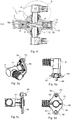
- Fastening means 54 are arranged outside the housing 2 to assemble the detection means 5 with the housing 2.
- the fixing means 54 comprise a plate 59 having a threaded perforation 60 in which is screwed a portion of the detection means 5 which is outside the housing 2.
- this perforation 60 has a female thread complementary to a thread external male to the detection means 5.
- a portion of the groove 52 which is outside the passage passes through this plate 59 and extends to the outside of the sensor.
- the plate 59 is fixed against an outer surface 61 of the housing 2 which, in this case is a flat surface.
- the threaded perforation 60 is of such dimensions that it opposes the passage of the ring 141 through the perforation 60.
- the plate 59 forms an axial abutment opposing the exit of the ring from the passage 31.
- the plate 59 has lateral perforations 63 arranged around the threaded perforation 60 so as to allow the passage of clamping bolts 64.
- These clamping bolts 64 are threaded in complementary perforations made in the housing 2. These clamping bolts 64 allow to tighten the plate 59 against the housing 2.
- the fixing means 54 of the detection means 5 also have a washer 55 coaxial with the axis XX and in which passes a portion of the detection means 5 which is outside the housing 2.
- This washer 55 has central tabs 56 and peripheral 57, the central tongue 56 penetrates inside the groove 52 so as to prohibit a relative rotation between the washer 55 and the detection means 5.
- the peripheral tongue 57 enters a complementary housing 58 fixed relative to the housing 2 so as to prohibit the relative rotation between the washer 55 and the housing 2. This washer 55 is thus arranged to index rotationally the detection means 5 with respect to the housing 2.
- the fastening means 54 also comprise a clamping nut 62 of the washer 55 against the plate 59. This nut 62 is screwed onto the part of the detection means 5 which is outside the housing 2 and in which extends a part of the groove 52.
- the housing 58 in which penetrates the peripheral tongue 57 of the washer 55 is formed through the plate 59.
- This housing 58 is made away from the threaded perforation 60 in which is screwed the part of the detection means 5 which is at As the washer 55 is placed between the nut 62 and the plate 59 which are threaded on the male thread of the detection means 5, there is an axial positioning effect of the detection means 5 with respect to the housing. 2.
- the tongues of the washer have an immobilizing effect in rotation, about the axis XX, detection means 5 with respect to the housing 2.
- the housing further has second and third openings 7 and 10 extending between the volume 3 and the outside of the housing.
- Actuating means 6 pass through the second opening 7 of the housing 2. These actuating means 6 are arranged to control the moving said movable part 4 from a second external zone Z2 to the housing 2.
- Second sealing means 9 are arranged relative to the housing 2 and the actuating means 6 to oppose the passage of fluid from the second external zone Z2 to the housing 2 to said internal volume 3 and via the second opening 7 .
- the actuating means 6 which pass through the second opening 7 comprise a lever 18 having first and second portions 18a, 18b located on either side of a spherical portion 18c of the lever.
- the first lever part 18a is located inside the internal volume 3 and bears against the moving part 4.
- the second part 18b of the lever 18 extends into the second external zone Z2 and is arranged so that the piston 22 can come into contact with this second part 18b at least when this piston 22 arrives in one of its end-of-travel positions inside the jack 21.
- a cable gland grips the spherical portion 18c of the lever to enable it to pivot relative to the gland in at least one pivot axis perpendicular to a main axis 20 of the lever 18.
- the lever 18 is a piece s' extending longitudinally along this main axis 20, this lever being preferably a part of revolution.
- This stuffing box belongs to the second sealing means 9 and seals against the spherical portion 18c of the lever 18, all around this spherical portion 18c to prevent the passage of fluid between the second zone Z2 and the internal volume 3.
- the third opening 10 is made to insert the movable part 4 which is cylindrical in the internal volume 3.
- Third sealing means 12 comprising a threaded plug 15 are arranged to prevent the passage of fluid between the internal volume 3 and a third external zone Z3 to the housing. This plug 15 is threaded into the third opening 10 of the internal volume 3.
- the first, second and third sealing means 14, 9, 12 are dimensioned so as to withstand a pressure differential of at least 300 kPa, this value corresponding to the difference between a pressure prevailing inside the internal volume and a pressure prevailing at the third external zone Z3 to the housing 2.
- this value of 300 kPa corresponds approximately to twice the differential pressure existing between an atmospheric pressure measured at 0 m altitude and an atmospheric pressure measured at 12 000 m altitude.
- first, second and third sealing means resist changes in ambient pressure to which the aircraft is subjected during its flights.
- a return spring 17 exerts on the moving part 4, an elastic return force to a first position of sliding in the internal volume 3.
- This first position here corresponds to the position occupied by this part 4 when the piston 22 is in a position remote from its limit switches.
- This return spring 17 is compressed between the plug 15 and the moving part 4 against which it is supported.
- the spring 17 allows an elastic return of the lever 18 to a position in which it is located when it is not in contact with the piston 22.
- the system according to the invention is placed to detect the moment when the undercarriage is completely extended / deployed and where the strut 28 of the undercarriage must be blocked to prevent an involuntary return of the undercarriage to its retracted position.
- the senor according to the invention comprises two detection means 51 placed on either side of the housing to detect the position of the moving part 4 in the internal volume 3.
- Each of these detecting means passes through a passage 31 which is clean.
- These passages 31 are vis-à-vis each other.
- the detecting means 51 thus positioned are redundant in order to be able to secure the detection of the displacement position of the part 4. It should be noted that these detection means can also be arranged to interact with each other as a function of the position of the part 4 with respect to to these detection means 5.
Landscapes
- Physics & Mathematics (AREA)
- General Physics & Mathematics (AREA)
- Engineering & Computer Science (AREA)
- Mechanical Engineering (AREA)
- Aviation & Aerospace Engineering (AREA)
- Measuring Fluid Pressure (AREA)
- Actuator (AREA)
Claims (14)
- Sensor (1), umfassend:- ein Gehäuse (2), das ein im Inneren des Gehäuses befindliches Innenvolumen (3) begrenzt und einen Durchgang (31) aufweist, der sich zwischen diesem Innenvolumen und einer außerhalb des Gehäuses befindlichen ersten äußeren Zone (Z1) erstreckt;- ein bewegliches Teil (4) im Inneren des Innenvolumens (3) des Gehäuses;- Detektionsmittel (5) zum Erfassen einer Verschiebung des genannten beweglichen Teils (4) in Bezug auf das Gehäuse (2), wobei diese Detektionsmittel (5) einen Detektionsabschnitt (51) umfassen, der sich in dem Durchgang (31) zwischen der außerhalb des Gehäuses befindlichen ersten äußeren Zone (Z1) und dem im Inneren des Gehäuses befindlichen Innenvolumen (3) erstreckt, wobei dieser Detektionsabschnitt (51) ebenfalls eine Nut (52) aufweist, die zur Außenseite des Detektionsabschnitts (51) hin zwecks Ausrichtung des Abschnittes der Detektionsmittel (5) in Bezug auf das Gehäuse (2) offen ist, wobei sich diese Nut (52) zwischen der außerhalb des Gehäuses befindlichen ersten äußeren Zone (Z1) und dem im Inneren des Gehäuses befindlichen Innenvolumen (3) erstreckt, dadurch gekennzeichnet, dass er erste Dichtungsmittel (14) umfasst, die um den Detelctionsabschnitt (51) herum angeordnet und im inneren des Durchgangs (31) platziert sind, wobei diese ersten Dichtungsmittel (14) so ausgebildet sind, dass sie den Durchtritt von Fluid zwischen dem Innenvolumen (3) und der außerhalb des Gehäuses (2) befindlichen ersten äußeren Zone (Z1) über die genannte Nut (52) unterbinden.
- Sensor (1) nach Anspruch 1, bei dem mindestens ein Abschnitt der Länge der Nut (52) mit einem Dichtungsmaterial (53) gefüllt ist, das so ausgebildet ist, dass es sich dem Durchtritt des Fluids zwischen dem Innenvolumen (3) und der außerhalb des Gehäuses befindlichen ersten äußeren Zone (Z1) über die Nut (52) widersetzt.
- Sensor nach Anspruch 2, bei dem diese ersten Dichtungsmittel (14) einen ringförmigen Ring (141) umfassen, der auf dichte Weise im Inneren des Durchgangs (31) montiert ist, um eine Buchse zur Translationsführung des Detektionsabschnittes (51) im Inneren des Durchgangs (31) und in Bezug auf das Gehäuse (2) zu bilden, wobei der Detektionsabschnitt (51) auf dichte Weise im Inneren des Ringes (141) montiert ist, wobei der im Inneren des Durchgangs (31) montierte Ring (141) und der im Inneren des Ringes (141) montierte Detektionsabschnitt (51) eine dichte Einheit bilden, die sich dem Durchtritt von Fluid zwischen dem Innenvolumen (3) und der ersten äußeren Zone (Z1) widersetzt.
- Sensor (1) nach Anspruch 3, bei dem diese ersten Dichtungsmittel (14) eine ringförmige Dichtung (142) umfassen, die um den Ring herum angeordnet und so ausgebildet ist, dass sie sich dem Durchtritt von Fluid zwischen dem Innenvolumen (3) und der ersten äußeren Zone (Z1) über das Äußere des Ringes (141) widersetzt.
- Sensor nach einem der vorhergehenden Ansprüche, bei dem der Detektionsabschnitt (51) eine gerade zylindrische Form hat und sich um und entlang einer Längssymmetrieachse (X-X) erstreckt, wobei die Nut (52) geradlinig ist und sich parallel zu dieser Längssymmetrieachse (X-X) erstreckt.
- Sensor (1) nach einem der vorhergehenden Ansprüche, ferner umfassend Befestigungsmittel (54), die außerhalb des Gehäuses (2) ausgebildet sind, um die Detektionsmittel (5) mit dem Gehäuse (2) zu verbinden, wobei diese Befestigungsmittel (54) eine Unterlegscheibe (55) aufweisen, in der ein Teil der Detektionsmittel (5) verläuft, der sich außerhalb des Gehäuses (2) befindet und in dem sich ein Teil der Nut (52) erstreckt, wobei diese Unterlegscheibe (55) zentrale Zungen (56) und Umfangszungen (57) aufweist, wobei die zentrale Zunge (56) derart in das Innere der Nut (52) eindringt, dass sie eine relative Drehung zwischen der Unterlegscheibe (55) und den Detektionsmitteln (5) unterbindet, wobei die Umfangszunge (57) derart in eine in Bezug auf das Gehäuse (2) ortsfeste komplementäre Aufnahme (58) eindringt, dass sie eine relative Drehung zwischen der Unterlegscheibe (55) und dem Gehäuse (2) unterbindet, wobei diese Unterlegscheibe (55) angeordnet ist, um die Detektionsmittel (5) in Bezug auf das Gehäuse (2) in Drehung zu indexieren.
- Sensor (1) nach Anspruch 6, bei dem die Befestigungsmittel (54) eine Platine (59) umfassen, die eine mit einem Gewinde versehene Lochung (60) aufweist, in die der Teil der Detektionsmittel (5) geschraubt ist, der sich außerhalb des Gehäuses (2) befindet und in dem sich ein Teil der Nut (52) erstreckt, wobei diese Platine (59) ferner an einer Außenfläche (61) des Gehäuses (2) befestigt ist.
- Sensor (1) nach den Ansprüchen 6 und 7, bei dem die Befestigungsmittel (54) eine Klemmutter (62) zum Festklemmen der Unterlegscheibe (55) an der Platine (59) umfassen, wobei diese Mutter (62) auf den Teil der Detektionsmittel (59) geschraubt ist, der sich außerhalb des Gehäuses (2) befindet und in dem sich ein Teil der Nut (52) erstreckt.
- Sensor nach einem der vorhergehenden Ansprüche, ferner umfassend:- Betätigungsmittel (6), die durch eine zweite Öffnung (7) gehen, die in dem Gehäuse (2) ausgebildet ist, wobei diese Betätigungsmittel (6) so ausgebildet sind, dass sie die Verschiebung des im Inneren des Innenvolumens (3) befindlichen beweglichen Teils (4) von einer außerhalb des Gehäuses (2) befindlichen zweiten äußeren Zone (Z2) steuern;- zweite Dichtungsmittel (9), die in Bezug auf das Gehäuse (2) und die Betätigungsmittel (6) so ausgebildet sind, dass sie sich dem Durchtritt von Fluid, das aus der außerhalb des Gehäuses (2) befindlichen zweiten äußeren Zone (Z2) stammt, in Richtung des Innenvolumens (3) des Gehäuses über die zweite Öffnung (7) des Gehäuses widersetzen,- eine dritte Öffnung (10), die sich zwischen dem Innenvolumen (3) des Gehäuses (2) und einer außerhalb des Gehäuses (2) befindlichen dritten äußeren Zone (Z3) erstreckt, die von der ersten und der zweiten äußeren Zone (Z1, Z2) des Gehäuses entfernt ist; und- dritte Dichtungsmittel (12), die so ausgebildet sind, dass sie sich dem Durchtritt von Fluid zwischen dem Innenvolumen (3) des Gehäuses (2) und der dritten äußeren Zone (Z3) über die dritte Öffnung (10) widersetzen.
- Sensor nach mindestens einem der Ansprüche 1 bis 9, bei dem die Detektionsmittel (5) elektronische Komponenten umfassen, die zum Innenvolumen (3) beabstandet sind und sich in dem Durchgang (31) des Gehäuses erstrecken.
- Sensor nach Anspruch 9, bei dem die dritten Dichtungsmittel (12) einen Stopfen (15) umfassen, der in der dritten Öffnung (10) des Innenvolumens (3) montiert ist, wobei dieser Stopfen (15) mittels eines Gewindes am Gehäuse (2) montiert ist.
- Sensor nach dem vorhergehenden Anspruch, bei dem das bewegliche Teil (4) im Inneren des Innenvolumens (3) des Gehäuses verschiebbar ist und eine Rückstellfeder (17) auf dieses bewegliche Teil (4) eine elastische Rückstellkraft zur Rückstellung in eine erste Position ausübt, wobei diese Rückstellfeder (17) zwischen dem Stopfen (15) und dem beweglichen Teil (4), an denen sie anliegt, zusammengedrückt ist.
- System, umfassend einen Sensor nach einem der vorhergehenden Ansprüche, kombiniert mit Anspruch 9, wobei dieses System ferner einen Hydraulikzylinder (21) umfasst, der einen Kolben (22) und eine Hydraulikkammer (23) enthält, in der dieser Kolben (22) gleitet, wobei sich die außerhalb des Gehäuses (2) befindliche zweite äußere Zone (Z2) und ein Abschnitt der Betätigungsmittel (6) im Inneren der Hydraulikkammer (23) des Zylinders (21) befinden, derart, dass eine Verschiebung des Kolbens (22) in der Hydraulikkammer (23) die Verschiebung der Betätigungsmittel (6) steuern und die Verschiebung des beweglichen Teils (4) in dem Innenvolumen (3) des Gehäuses (2) des Sensors (1) bewirken kann.
- System nach Anspruch 13, bei dem der Hydraulikzylinder (21) ein Hydraulikzylinder zum Ausfahren und Einfahren eines Luftfahrzeugfahrwerks ist.
Applications Claiming Priority (1)
| Application Number | Priority Date | Filing Date | Title |
|---|---|---|---|
| FR1458926A FR3026178B1 (fr) | 2014-09-22 | 2014-09-22 | Capteur de proximite pour aeronef dote d'un assemblage etanche particulier |
Publications (2)
| Publication Number | Publication Date |
|---|---|
| EP2998709A1 EP2998709A1 (de) | 2016-03-23 |
| EP2998709B1 true EP2998709B1 (de) | 2017-11-01 |
Family
ID=51987340
Family Applications (1)
| Application Number | Title | Priority Date | Filing Date |
|---|---|---|---|
| EP15183769.7A Active EP2998709B1 (de) | 2014-09-22 | 2015-09-03 | Näherungssensor für luftfahrzeug, das mit einer besonderen wasserdichten anordnung ausgestattet ist |
Country Status (4)
| Country | Link |
|---|---|
| US (1) | US9784600B2 (de) |
| EP (1) | EP2998709B1 (de) |
| CA (1) | CA2905054C (de) |
| FR (1) | FR3026178B1 (de) |
Cited By (1)
| Publication number | Priority date | Publication date | Assignee | Title |
|---|---|---|---|---|
| DE202022100277U1 (de) | 2022-01-19 | 2023-04-21 | Liebherr-Aerospace Lindenberg Gmbh | Verriegelungserfassungseinrichtung |
Families Citing this family (1)
| Publication number | Priority date | Publication date | Assignee | Title |
|---|---|---|---|---|
| CN113049019B (zh) * | 2019-12-26 | 2022-09-20 | 中国航空工业集团公司西安飞机设计研究所 | 一种磁感式接近传感器圆周相对运动试验台 |
Family Cites Families (4)
| Publication number | Priority date | Publication date | Assignee | Title |
|---|---|---|---|---|
| JP2009503454A (ja) * | 2005-07-20 | 2009-01-29 | ザ ティムケン カンパニー | センサアセンブリ |
| DE102005060676B4 (de) | 2005-12-19 | 2021-01-21 | Asm Automation Sensorik Messtechnik Gmbh | Positionssensor in Stabbauweise sowie Verfahren zum Austausch |
| DE102006043291A1 (de) * | 2006-09-14 | 2008-03-27 | Zf Friedrichshafen Ag | Berührungsloser Drehwinkelsensor |
| DE102007037759A1 (de) * | 2007-08-10 | 2009-02-12 | Schaeffler Kg | Vorrichtung zum Bestimmen einer Schaltstellung eines mechanischen Systems |
-
2014
- 2014-09-22 FR FR1458926A patent/FR3026178B1/fr active Active
-
2015
- 2015-09-03 EP EP15183769.7A patent/EP2998709B1/de active Active
- 2015-09-10 US US14/849,893 patent/US9784600B2/en active Active
- 2015-09-18 CA CA2905054A patent/CA2905054C/fr active Active
Non-Patent Citations (1)
| Title |
|---|
| None * |
Cited By (1)
| Publication number | Priority date | Publication date | Assignee | Title |
|---|---|---|---|---|
| DE202022100277U1 (de) | 2022-01-19 | 2023-04-21 | Liebherr-Aerospace Lindenberg Gmbh | Verriegelungserfassungseinrichtung |
Also Published As
| Publication number | Publication date |
|---|---|
| US9784600B2 (en) | 2017-10-10 |
| CA2905054C (fr) | 2018-01-02 |
| CA2905054A1 (fr) | 2016-03-22 |
| FR3026178A1 (de) | 2016-03-25 |
| US20160084681A1 (en) | 2016-03-24 |
| EP2998709A1 (de) | 2016-03-23 |
| FR3026178B1 (fr) | 2018-05-18 |
Similar Documents
| Publication | Publication Date | Title |
|---|---|---|
| EP2440806B1 (de) | Stossdämpfer und mit solch einem stossdämpfer versehenes fahrwerk | |
| EP3074671B1 (de) | Absperrventil mit einer vakuumkammer | |
| EP2998709B1 (de) | Näherungssensor für luftfahrzeug, das mit einer besonderen wasserdichten anordnung ausgestattet ist | |
| EP3071858A2 (de) | Gleitende sattelscheibenbremse mit entlüftung zwischen stiften und bohrungen | |
| EP3092368B1 (de) | Isoliervorrichtung für ein bohrloch | |
| US20180106312A1 (en) | Bleeding valve, a hydraulic fitting and a venting assembly for a bicycle hydraulic braking system | |
| EP3785803B1 (de) | Ventil und system zur auftragung eines beschichtungsprodukts, das ein solches ventil umfasst | |
| EP3051150B1 (de) | Näherungssensor für luftfahrzeug, der mit einer hydraulischen sicherung ausgestattet ist | |
| FR3094444A1 (fr) | Dispositif joint tournant configuré pour équiper une installation d’exploitation de fluides, notamment sur une plateforme offshore | |
| FR3016007A1 (fr) | Dispositif d'actionnement d'urgence notamment destine a un ouvrant d'aeronef | |
| EP2570326B1 (de) | Vorrichtung für den Flüssigkeitsabfluss und den Luftaustausch für die Lenkung eines Kraftfahrzeugs | |
| EP3017210B1 (de) | Bremsvorrichtung mit einem kolben mit vollständiger rückstossfunktion | |
| CA3154857C (fr) | Dispositif d'echappement anti propagation de batteries lithium-ion d'aeronef | |
| EP2166233B1 (de) | Zylinder mit progressiver Wirkung | |
| FR3064595A1 (fr) | Ensemble deployable, aeronef et procede de deploiement associes | |
| FR2970055A1 (fr) | Dispositif d'etancheite par siege-annulaire | |
| EP3027884B1 (de) | Integrierte anordnung eines hochdruckventils und einer injektionsrampe | |
| FR3003327A1 (fr) | Dispositif d obturation d un systeme hydraulique systeme hydraulique et aeronef | |
| EP3237723B1 (de) | Vorrichtung zum isolieren eines teils eines bohrlochs oder einer rohrleitung sowie in solch einer isolierungsvorrichtung implementierte steuerungseinrichtungen | |
| FR3013320A1 (fr) | Engin sous-marin equipe d'au moins une bouee munie d'un organe fonctionnel | |
| EP1069354A1 (de) | Rückflussverhinder | |
| WO2015044586A1 (fr) | Dispositif de raccord hydraulique et système de transfert de fluide utilisant ce dispositif | |
| FR2511469A3 (fr) | Dispositif de fermeture-vanne de securite pour le controle du passage d | |
| FR2917140A1 (fr) | Verin a action progressive |
Legal Events
| Date | Code | Title | Description |
|---|---|---|---|
| PUAI | Public reference made under article 153(3) epc to a published international application that has entered the european phase |
Free format text: ORIGINAL CODE: 0009012 |
|
| AK | Designated contracting states |
Kind code of ref document: A1 Designated state(s): AL AT BE BG CH CY CZ DE DK EE ES FI FR GB GR HR HU IE IS IT LI LT LU LV MC MK MT NL NO PL PT RO RS SE SI SK SM TR |
|
| AX | Request for extension of the european patent |
Extension state: BA ME |
|
| 17P | Request for examination filed |
Effective date: 20160826 |
|
| RBV | Designated contracting states (corrected) |
Designated state(s): AL AT BE BG CH CY CZ DE DK EE ES FI FR GB GR HR HU IE IS IT LI LT LU LV MC MK MT NL NO PL PT RO RS SE SI SK SM TR |
|
| RAP1 | Party data changed (applicant data changed or rights of an application transferred) |
Owner name: SAFRAN LANDING SYSTEMS |
|
| RAP1 | Party data changed (applicant data changed or rights of an application transferred) |
Owner name: SAFRAN LANDING SYSTEMS |
|
| GRAP | Despatch of communication of intention to grant a patent |
Free format text: ORIGINAL CODE: EPIDOSNIGR1 |
|
| STAA | Information on the status of an ep patent application or granted ep patent |
Free format text: STATUS: GRANT OF PATENT IS INTENDED |
|
| INTG | Intention to grant announced |
Effective date: 20170509 |
|
| GRAS | Grant fee paid |
Free format text: ORIGINAL CODE: EPIDOSNIGR3 |
|
| GRAA | (expected) grant |
Free format text: ORIGINAL CODE: 0009210 |
|
| STAA | Information on the status of an ep patent application or granted ep patent |
Free format text: STATUS: THE PATENT HAS BEEN GRANTED |
|
| AK | Designated contracting states |
Kind code of ref document: B1 Designated state(s): AL AT BE BG CH CY CZ DE DK EE ES FI FR GB GR HR HU IE IS IT LI LT LU LV MC MK MT NL NO PL PT RO RS SE SI SK SM TR |
|
| REG | Reference to a national code |
Ref country code: GB Ref legal event code: FG4D Free format text: NOT ENGLISH |
|
| REG | Reference to a national code |
Ref country code: CH Ref legal event code: EP Ref country code: AT Ref legal event code: REF Ref document number: 942497 Country of ref document: AT Kind code of ref document: T Effective date: 20171115 |
|
| REG | Reference to a national code |
Ref country code: IE Ref legal event code: FG4D Free format text: LANGUAGE OF EP DOCUMENT: FRENCH |
|
| REG | Reference to a national code |
Ref country code: DE Ref legal event code: R096 Ref document number: 602015005700 Country of ref document: DE |
|
| REG | Reference to a national code |
Ref country code: NL Ref legal event code: MP Effective date: 20171101 |
|
| REG | Reference to a national code |
Ref country code: LT Ref legal event code: MG4D |
|
| REG | Reference to a national code |
Ref country code: AT Ref legal event code: MK05 Ref document number: 942497 Country of ref document: AT Kind code of ref document: T Effective date: 20171101 |
|
| PG25 | Lapsed in a contracting state [announced via postgrant information from national office to epo] |
Ref country code: SE Free format text: LAPSE BECAUSE OF FAILURE TO SUBMIT A TRANSLATION OF THE DESCRIPTION OR TO PAY THE FEE WITHIN THE PRESCRIBED TIME-LIMIT Effective date: 20171101 Ref country code: NL Free format text: LAPSE BECAUSE OF FAILURE TO SUBMIT A TRANSLATION OF THE DESCRIPTION OR TO PAY THE FEE WITHIN THE PRESCRIBED TIME-LIMIT Effective date: 20171101 Ref country code: FI Free format text: LAPSE BECAUSE OF FAILURE TO SUBMIT A TRANSLATION OF THE DESCRIPTION OR TO PAY THE FEE WITHIN THE PRESCRIBED TIME-LIMIT Effective date: 20171101 Ref country code: NO Free format text: LAPSE BECAUSE OF FAILURE TO SUBMIT A TRANSLATION OF THE DESCRIPTION OR TO PAY THE FEE WITHIN THE PRESCRIBED TIME-LIMIT Effective date: 20180201 Ref country code: ES Free format text: LAPSE BECAUSE OF FAILURE TO SUBMIT A TRANSLATION OF THE DESCRIPTION OR TO PAY THE FEE WITHIN THE PRESCRIBED TIME-LIMIT Effective date: 20171101 Ref country code: LT Free format text: LAPSE BECAUSE OF FAILURE TO SUBMIT A TRANSLATION OF THE DESCRIPTION OR TO PAY THE FEE WITHIN THE PRESCRIBED TIME-LIMIT Effective date: 20171101 |
|
| PG25 | Lapsed in a contracting state [announced via postgrant information from national office to epo] |
Ref country code: AT Free format text: LAPSE BECAUSE OF FAILURE TO SUBMIT A TRANSLATION OF THE DESCRIPTION OR TO PAY THE FEE WITHIN THE PRESCRIBED TIME-LIMIT Effective date: 20171101 Ref country code: GR Free format text: LAPSE BECAUSE OF FAILURE TO SUBMIT A TRANSLATION OF THE DESCRIPTION OR TO PAY THE FEE WITHIN THE PRESCRIBED TIME-LIMIT Effective date: 20180202 Ref country code: RS Free format text: LAPSE BECAUSE OF FAILURE TO SUBMIT A TRANSLATION OF THE DESCRIPTION OR TO PAY THE FEE WITHIN THE PRESCRIBED TIME-LIMIT Effective date: 20171101 Ref country code: BG Free format text: LAPSE BECAUSE OF FAILURE TO SUBMIT A TRANSLATION OF THE DESCRIPTION OR TO PAY THE FEE WITHIN THE PRESCRIBED TIME-LIMIT Effective date: 20180201 Ref country code: LV Free format text: LAPSE BECAUSE OF FAILURE TO SUBMIT A TRANSLATION OF THE DESCRIPTION OR TO PAY THE FEE WITHIN THE PRESCRIBED TIME-LIMIT Effective date: 20171101 Ref country code: HR Free format text: LAPSE BECAUSE OF FAILURE TO SUBMIT A TRANSLATION OF THE DESCRIPTION OR TO PAY THE FEE WITHIN THE PRESCRIBED TIME-LIMIT Effective date: 20171101 Ref country code: IS Free format text: LAPSE BECAUSE OF FAILURE TO SUBMIT A TRANSLATION OF THE DESCRIPTION OR TO PAY THE FEE WITHIN THE PRESCRIBED TIME-LIMIT Effective date: 20180301 |
|
| PG25 | Lapsed in a contracting state [announced via postgrant information from national office to epo] |
Ref country code: DK Free format text: LAPSE BECAUSE OF FAILURE TO SUBMIT A TRANSLATION OF THE DESCRIPTION OR TO PAY THE FEE WITHIN THE PRESCRIBED TIME-LIMIT Effective date: 20171101 Ref country code: SK Free format text: LAPSE BECAUSE OF FAILURE TO SUBMIT A TRANSLATION OF THE DESCRIPTION OR TO PAY THE FEE WITHIN THE PRESCRIBED TIME-LIMIT Effective date: 20171101 Ref country code: CZ Free format text: LAPSE BECAUSE OF FAILURE TO SUBMIT A TRANSLATION OF THE DESCRIPTION OR TO PAY THE FEE WITHIN THE PRESCRIBED TIME-LIMIT Effective date: 20171101 Ref country code: EE Free format text: LAPSE BECAUSE OF FAILURE TO SUBMIT A TRANSLATION OF THE DESCRIPTION OR TO PAY THE FEE WITHIN THE PRESCRIBED TIME-LIMIT Effective date: 20171101 Ref country code: CY Free format text: LAPSE BECAUSE OF FAILURE TO SUBMIT A TRANSLATION OF THE DESCRIPTION OR TO PAY THE FEE WITHIN THE PRESCRIBED TIME-LIMIT Effective date: 20171101 |
|
| REG | Reference to a national code |
Ref country code: DE Ref legal event code: R097 Ref document number: 602015005700 Country of ref document: DE |
|
| REG | Reference to a national code |
Ref country code: FR Ref legal event code: PLFP Year of fee payment: 4 |
|
| PG25 | Lapsed in a contracting state [announced via postgrant information from national office to epo] |
Ref country code: PL Free format text: LAPSE BECAUSE OF FAILURE TO SUBMIT A TRANSLATION OF THE DESCRIPTION OR TO PAY THE FEE WITHIN THE PRESCRIBED TIME-LIMIT Effective date: 20171101 Ref country code: RO Free format text: LAPSE BECAUSE OF FAILURE TO SUBMIT A TRANSLATION OF THE DESCRIPTION OR TO PAY THE FEE WITHIN THE PRESCRIBED TIME-LIMIT Effective date: 20171101 Ref country code: IT Free format text: LAPSE BECAUSE OF FAILURE TO SUBMIT A TRANSLATION OF THE DESCRIPTION OR TO PAY THE FEE WITHIN THE PRESCRIBED TIME-LIMIT Effective date: 20171101 Ref country code: SM Free format text: LAPSE BECAUSE OF FAILURE TO SUBMIT A TRANSLATION OF THE DESCRIPTION OR TO PAY THE FEE WITHIN THE PRESCRIBED TIME-LIMIT Effective date: 20171101 |
|
| PLBE | No opposition filed within time limit |
Free format text: ORIGINAL CODE: 0009261 |
|
| STAA | Information on the status of an ep patent application or granted ep patent |
Free format text: STATUS: NO OPPOSITION FILED WITHIN TIME LIMIT |
|
| PG25 | Lapsed in a contracting state [announced via postgrant information from national office to epo] |
Ref country code: MT Free format text: LAPSE BECAUSE OF FAILURE TO SUBMIT A TRANSLATION OF THE DESCRIPTION OR TO PAY THE FEE WITHIN THE PRESCRIBED TIME-LIMIT Effective date: 20171101 |
|
| 26N | No opposition filed |
Effective date: 20180802 |
|
| PG25 | Lapsed in a contracting state [announced via postgrant information from national office to epo] |
Ref country code: SI Free format text: LAPSE BECAUSE OF FAILURE TO SUBMIT A TRANSLATION OF THE DESCRIPTION OR TO PAY THE FEE WITHIN THE PRESCRIBED TIME-LIMIT Effective date: 20171101 |
|
| PG25 | Lapsed in a contracting state [announced via postgrant information from national office to epo] |
Ref country code: MC Free format text: LAPSE BECAUSE OF FAILURE TO SUBMIT A TRANSLATION OF THE DESCRIPTION OR TO PAY THE FEE WITHIN THE PRESCRIBED TIME-LIMIT Effective date: 20171101 |
|
| REG | Reference to a national code |
Ref country code: CH Ref legal event code: PL |
|
| REG | Reference to a national code |
Ref country code: BE Ref legal event code: MM Effective date: 20180930 |
|
| REG | Reference to a national code |
Ref country code: IE Ref legal event code: MM4A |
|
| PG25 | Lapsed in a contracting state [announced via postgrant information from national office to epo] |
Ref country code: LU Free format text: LAPSE BECAUSE OF NON-PAYMENT OF DUE FEES Effective date: 20180903 |
|
| PG25 | Lapsed in a contracting state [announced via postgrant information from national office to epo] |
Ref country code: IE Free format text: LAPSE BECAUSE OF NON-PAYMENT OF DUE FEES Effective date: 20180903 |
|
| PG25 | Lapsed in a contracting state [announced via postgrant information from national office to epo] |
Ref country code: LI Free format text: LAPSE BECAUSE OF NON-PAYMENT OF DUE FEES Effective date: 20180930 Ref country code: CH Free format text: LAPSE BECAUSE OF NON-PAYMENT OF DUE FEES Effective date: 20180930 Ref country code: BE Free format text: LAPSE BECAUSE OF NON-PAYMENT OF DUE FEES Effective date: 20180930 |
|
| PG25 | Lapsed in a contracting state [announced via postgrant information from national office to epo] |
Ref country code: TR Free format text: LAPSE BECAUSE OF FAILURE TO SUBMIT A TRANSLATION OF THE DESCRIPTION OR TO PAY THE FEE WITHIN THE PRESCRIBED TIME-LIMIT Effective date: 20171101 |
|
| PG25 | Lapsed in a contracting state [announced via postgrant information from national office to epo] |
Ref country code: PT Free format text: LAPSE BECAUSE OF FAILURE TO SUBMIT A TRANSLATION OF THE DESCRIPTION OR TO PAY THE FEE WITHIN THE PRESCRIBED TIME-LIMIT Effective date: 20171101 |
|
| PG25 | Lapsed in a contracting state [announced via postgrant information from national office to epo] |
Ref country code: MK Free format text: LAPSE BECAUSE OF NON-PAYMENT OF DUE FEES Effective date: 20171101 Ref country code: HU Free format text: LAPSE BECAUSE OF FAILURE TO SUBMIT A TRANSLATION OF THE DESCRIPTION OR TO PAY THE FEE WITHIN THE PRESCRIBED TIME-LIMIT; INVALID AB INITIO Effective date: 20150903 |
|
| PG25 | Lapsed in a contracting state [announced via postgrant information from national office to epo] |
Ref country code: AL Free format text: LAPSE BECAUSE OF FAILURE TO SUBMIT A TRANSLATION OF THE DESCRIPTION OR TO PAY THE FEE WITHIN THE PRESCRIBED TIME-LIMIT Effective date: 20171101 |
|
| PGFP | Annual fee paid to national office [announced via postgrant information from national office to epo] |
Ref country code: GB Payment date: 20230823 Year of fee payment: 9 |
|
| PGFP | Annual fee paid to national office [announced via postgrant information from national office to epo] |
Ref country code: FR Payment date: 20230822 Year of fee payment: 9 Ref country code: DE Payment date: 20230822 Year of fee payment: 9 |