EP2998700B1 - Dispositif de mesure de distance électro-optique et procédé de mesure de distance - Google Patents
Dispositif de mesure de distance électro-optique et procédé de mesure de distance Download PDFInfo
- Publication number
- EP2998700B1 EP2998700B1 EP14185404.2A EP14185404A EP2998700B1 EP 2998700 B1 EP2998700 B1 EP 2998700B1 EP 14185404 A EP14185404 A EP 14185404A EP 2998700 B1 EP2998700 B1 EP 2998700B1
- Authority
- EP
- European Patent Office
- Prior art keywords
- reception
- distance
- segments
- signal
- apd
- Prior art date
- Legal status (The legal status is an assumption and is not a legal conclusion. Google has not performed a legal analysis and makes no representation as to the accuracy of the status listed.)
- Active
Links
- 238000000034 method Methods 0.000 title claims description 14
- 230000003287 optical effect Effects 0.000 claims description 34
- 238000005259 measurement Methods 0.000 claims description 30
- 230000005540 biological transmission Effects 0.000 claims description 21
- 238000012545 processing Methods 0.000 claims description 17
- 238000011156 evaluation Methods 0.000 claims description 10
- 239000002245 particle Substances 0.000 claims description 8
- 238000000149 argon plasma sintering Methods 0.000 claims description 3
- 230000002093 peripheral effect Effects 0.000 claims description 2
- 238000009795 derivation Methods 0.000 claims 2
- 230000003068 static effect Effects 0.000 claims 1
- 238000011144 upstream manufacturing Methods 0.000 claims 1
- 230000000875 corresponding effect Effects 0.000 description 12
- 238000001514 detection method Methods 0.000 description 12
- 230000003321 amplification Effects 0.000 description 9
- 238000003199 nucleic acid amplification method Methods 0.000 description 9
- 230000005855 radiation Effects 0.000 description 7
- 230000003247 decreasing effect Effects 0.000 description 6
- 238000006073 displacement reaction Methods 0.000 description 6
- 230000007423 decrease Effects 0.000 description 5
- 210000003128 head Anatomy 0.000 description 5
- 230000011218 segmentation Effects 0.000 description 5
- 238000003491 array Methods 0.000 description 4
- 238000000098 azimuthal photoelectron diffraction Methods 0.000 description 4
- 238000005286 illumination Methods 0.000 description 4
- 230000001629 suppression Effects 0.000 description 4
- 239000000443 aerosol Substances 0.000 description 3
- 238000013461 design Methods 0.000 description 3
- 238000010586 diagram Methods 0.000 description 3
- 239000000428 dust Substances 0.000 description 3
- 238000005516 engineering process Methods 0.000 description 3
- 238000013459 approach Methods 0.000 description 2
- 230000008901 benefit Effects 0.000 description 2
- 238000011157 data evaluation Methods 0.000 description 2
- 230000001419 dependent effect Effects 0.000 description 2
- 238000005065 mining Methods 0.000 description 2
- 239000013307 optical fiber Substances 0.000 description 2
- 230000009467 reduction Effects 0.000 description 2
- 239000007787 solid Substances 0.000 description 2
- 239000000654 additive Substances 0.000 description 1
- 230000000996 additive effect Effects 0.000 description 1
- 230000009286 beneficial effect Effects 0.000 description 1
- 238000004364 calculation method Methods 0.000 description 1
- 230000008859 change Effects 0.000 description 1
- 239000008264 cloud Substances 0.000 description 1
- 230000001276 controlling effect Effects 0.000 description 1
- 230000002596 correlated effect Effects 0.000 description 1
- 239000013078 crystal Substances 0.000 description 1
- 230000004069 differentiation Effects 0.000 description 1
- 239000000835 fiber Substances 0.000 description 1
- 238000010304 firing Methods 0.000 description 1
- 239000003897 fog Substances 0.000 description 1
- 230000005484 gravity Effects 0.000 description 1
- 238000009499 grossing Methods 0.000 description 1
- 238000003384 imaging method Methods 0.000 description 1
- 238000001208 nuclear magnetic resonance pulse sequence Methods 0.000 description 1
- 238000005457 optimization Methods 0.000 description 1
- 230000010363 phase shift Effects 0.000 description 1
- 230000010287 polarization Effects 0.000 description 1
- 210000001747 pupil Anatomy 0.000 description 1
- 230000000630 rising effect Effects 0.000 description 1
- 238000005070 sampling Methods 0.000 description 1
- 230000001360 synchronised effect Effects 0.000 description 1
- 230000002123 temporal effect Effects 0.000 description 1
- 238000012360 testing method Methods 0.000 description 1
- 230000009466 transformation Effects 0.000 description 1
- 238000013519 translation Methods 0.000 description 1
Images


Classifications
-
- G—PHYSICS
- G01—MEASURING; TESTING
- G01C—MEASURING DISTANCES, LEVELS OR BEARINGS; SURVEYING; NAVIGATION; GYROSCOPIC INSTRUMENTS; PHOTOGRAMMETRY OR VIDEOGRAMMETRY
- G01C15/00—Surveying instruments or accessories not provided for in groups G01C1/00 - G01C13/00
- G01C15/002—Active optical surveying means
-
- G—PHYSICS
- G01—MEASURING; TESTING
- G01C—MEASURING DISTANCES, LEVELS OR BEARINGS; SURVEYING; NAVIGATION; GYROSCOPIC INSTRUMENTS; PHOTOGRAMMETRY OR VIDEOGRAMMETRY
- G01C3/00—Measuring distances in line of sight; Optical rangefinders
- G01C3/02—Details
- G01C3/06—Use of electric means to obtain final indication
- G01C3/08—Use of electric radiation detectors
-
- G—PHYSICS
- G01—MEASURING; TESTING
- G01S—RADIO DIRECTION-FINDING; RADIO NAVIGATION; DETERMINING DISTANCE OR VELOCITY BY USE OF RADIO WAVES; LOCATING OR PRESENCE-DETECTING BY USE OF THE REFLECTION OR RERADIATION OF RADIO WAVES; ANALOGOUS ARRANGEMENTS USING OTHER WAVES
- G01S17/00—Systems using the reflection or reradiation of electromagnetic waves other than radio waves, e.g. lidar systems
- G01S17/02—Systems using the reflection of electromagnetic waves other than radio waves
- G01S17/06—Systems determining position data of a target
- G01S17/08—Systems determining position data of a target for measuring distance only
- G01S17/10—Systems determining position data of a target for measuring distance only using transmission of interrupted, pulse-modulated waves
-
- G—PHYSICS
- G01—MEASURING; TESTING
- G01S—RADIO DIRECTION-FINDING; RADIO NAVIGATION; DETERMINING DISTANCE OR VELOCITY BY USE OF RADIO WAVES; LOCATING OR PRESENCE-DETECTING BY USE OF THE REFLECTION OR RERADIATION OF RADIO WAVES; ANALOGOUS ARRANGEMENTS USING OTHER WAVES
- G01S17/00—Systems using the reflection or reradiation of electromagnetic waves other than radio waves, e.g. lidar systems
- G01S17/02—Systems using the reflection of electromagnetic waves other than radio waves
- G01S17/06—Systems determining position data of a target
- G01S17/42—Simultaneous measurement of distance and other co-ordinates
-
- G—PHYSICS
- G01—MEASURING; TESTING
- G01S—RADIO DIRECTION-FINDING; RADIO NAVIGATION; DETERMINING DISTANCE OR VELOCITY BY USE OF RADIO WAVES; LOCATING OR PRESENCE-DETECTING BY USE OF THE REFLECTION OR RERADIATION OF RADIO WAVES; ANALOGOUS ARRANGEMENTS USING OTHER WAVES
- G01S7/00—Details of systems according to groups G01S13/00, G01S15/00, G01S17/00
- G01S7/48—Details of systems according to groups G01S13/00, G01S15/00, G01S17/00 of systems according to group G01S17/00
- G01S7/481—Constructional features, e.g. arrangements of optical elements
- G01S7/4816—Constructional features, e.g. arrangements of optical elements of receivers alone
-
- G—PHYSICS
- G01—MEASURING; TESTING
- G01S—RADIO DIRECTION-FINDING; RADIO NAVIGATION; DETERMINING DISTANCE OR VELOCITY BY USE OF RADIO WAVES; LOCATING OR PRESENCE-DETECTING BY USE OF THE REFLECTION OR RERADIATION OF RADIO WAVES; ANALOGOUS ARRANGEMENTS USING OTHER WAVES
- G01S7/00—Details of systems according to groups G01S13/00, G01S15/00, G01S17/00
- G01S7/48—Details of systems according to groups G01S13/00, G01S15/00, G01S17/00 of systems according to group G01S17/00
- G01S7/481—Constructional features, e.g. arrangements of optical elements
- G01S7/4817—Constructional features, e.g. arrangements of optical elements relating to scanning
-
- G—PHYSICS
- G01—MEASURING; TESTING
- G01S—RADIO DIRECTION-FINDING; RADIO NAVIGATION; DETERMINING DISTANCE OR VELOCITY BY USE OF RADIO WAVES; LOCATING OR PRESENCE-DETECTING BY USE OF THE REFLECTION OR RERADIATION OF RADIO WAVES; ANALOGOUS ARRANGEMENTS USING OTHER WAVES
- G01S7/00—Details of systems according to groups G01S13/00, G01S15/00, G01S17/00
- G01S7/48—Details of systems according to groups G01S13/00, G01S15/00, G01S17/00 of systems according to group G01S17/00
- G01S7/483—Details of pulse systems
- G01S7/486—Receivers
- G01S7/4861—Circuits for detection, sampling, integration or read-out
-
- H—ELECTRICITY
- H01—ELECTRIC ELEMENTS
- H01L—SEMICONDUCTOR DEVICES NOT COVERED BY CLASS H10
- H01L31/00—Semiconductor devices sensitive to infrared radiation, light, electromagnetic radiation of shorter wavelength or corpuscular radiation and specially adapted either for the conversion of the energy of such radiation into electrical energy or for the control of electrical energy by such radiation; Processes or apparatus specially adapted for the manufacture or treatment thereof or of parts thereof; Details thereof
- H01L31/02—Details
- H01L31/02016—Circuit arrangements of general character for the devices
- H01L31/02019—Circuit arrangements of general character for the devices for devices characterised by at least one potential jump barrier or surface barrier
- H01L31/02024—Position sensitive and lateral effect photodetectors; Quadrant photodiodes
-
- H—ELECTRICITY
- H01—ELECTRIC ELEMENTS
- H01L—SEMICONDUCTOR DEVICES NOT COVERED BY CLASS H10
- H01L31/00—Semiconductor devices sensitive to infrared radiation, light, electromagnetic radiation of shorter wavelength or corpuscular radiation and specially adapted either for the conversion of the energy of such radiation into electrical energy or for the control of electrical energy by such radiation; Processes or apparatus specially adapted for the manufacture or treatment thereof or of parts thereof; Details thereof
- H01L31/08—Semiconductor devices sensitive to infrared radiation, light, electromagnetic radiation of shorter wavelength or corpuscular radiation and specially adapted either for the conversion of the energy of such radiation into electrical energy or for the control of electrical energy by such radiation; Processes or apparatus specially adapted for the manufacture or treatment thereof or of parts thereof; Details thereof in which radiation controls flow of current through the device, e.g. photoresistors
- H01L31/10—Semiconductor devices sensitive to infrared radiation, light, electromagnetic radiation of shorter wavelength or corpuscular radiation and specially adapted either for the conversion of the energy of such radiation into electrical energy or for the control of electrical energy by such radiation; Processes or apparatus specially adapted for the manufacture or treatment thereof or of parts thereof; Details thereof in which radiation controls flow of current through the device, e.g. photoresistors characterised by potential barriers, e.g. phototransistors
- H01L31/101—Devices sensitive to infrared, visible or ultraviolet radiation
- H01L31/102—Devices sensitive to infrared, visible or ultraviolet radiation characterised by only one potential barrier
- H01L31/107—Devices sensitive to infrared, visible or ultraviolet radiation characterised by only one potential barrier the potential barrier working in avalanche mode, e.g. avalanche photodiodes
-
- H—ELECTRICITY
- H01—ELECTRIC ELEMENTS
- H01L—SEMICONDUCTOR DEVICES NOT COVERED BY CLASS H10
- H01L31/00—Semiconductor devices sensitive to infrared radiation, light, electromagnetic radiation of shorter wavelength or corpuscular radiation and specially adapted either for the conversion of the energy of such radiation into electrical energy or for the control of electrical energy by such radiation; Processes or apparatus specially adapted for the manufacture or treatment thereof or of parts thereof; Details thereof
- H01L31/12—Semiconductor devices sensitive to infrared radiation, light, electromagnetic radiation of shorter wavelength or corpuscular radiation and specially adapted either for the conversion of the energy of such radiation into electrical energy or for the control of electrical energy by such radiation; Processes or apparatus specially adapted for the manufacture or treatment thereof or of parts thereof; Details thereof structurally associated with, e.g. formed in or on a common substrate with, one or more electric light sources, e.g. electroluminescent light sources, and electrically or optically coupled thereto
- H01L31/16—Semiconductor devices sensitive to infrared radiation, light, electromagnetic radiation of shorter wavelength or corpuscular radiation and specially adapted either for the conversion of the energy of such radiation into electrical energy or for the control of electrical energy by such radiation; Processes or apparatus specially adapted for the manufacture or treatment thereof or of parts thereof; Details thereof structurally associated with, e.g. formed in or on a common substrate with, one or more electric light sources, e.g. electroluminescent light sources, and electrically or optically coupled thereto the semiconductor device sensitive to radiation being controlled by the light source or sources
- H01L31/165—Semiconductor devices sensitive to infrared radiation, light, electromagnetic radiation of shorter wavelength or corpuscular radiation and specially adapted either for the conversion of the energy of such radiation into electrical energy or for the control of electrical energy by such radiation; Processes or apparatus specially adapted for the manufacture or treatment thereof or of parts thereof; Details thereof structurally associated with, e.g. formed in or on a common substrate with, one or more electric light sources, e.g. electroluminescent light sources, and electrically or optically coupled thereto the semiconductor device sensitive to radiation being controlled by the light source or sources the semiconductor sensitive to radiation being characterised by at least one potential-jump or surface barrier
-
- G—PHYSICS
- G01—MEASURING; TESTING
- G01S—RADIO DIRECTION-FINDING; RADIO NAVIGATION; DETERMINING DISTANCE OR VELOCITY BY USE OF RADIO WAVES; LOCATING OR PRESENCE-DETECTING BY USE OF THE REFLECTION OR RERADIATION OF RADIO WAVES; ANALOGOUS ARRANGEMENTS USING OTHER WAVES
- G01S7/00—Details of systems according to groups G01S13/00, G01S15/00, G01S17/00
- G01S7/48—Details of systems according to groups G01S13/00, G01S15/00, G01S17/00 of systems according to group G01S17/00
- G01S7/483—Details of pulse systems
- G01S7/486—Receivers
- G01S7/4868—Controlling received signal intensity or exposure of sensor
Definitions
- the invention relates to an electro-optical distance measuring device and distance measuring method.
- the distance and angle from a measuring device to a target point to be measured are recorded as spatial standard data and, in particular, the location of the measuring device together with any existing reference points are recorded.
- Such surveying equipment is used for detecting three-dimensional objects or surfaces. These devices typically scan a three-dimensional structure, such as the structure of a building, with laser pulses successively and then calculate from the retrieved reflection pulses a corresponding three-dimensional Model describing the surface of the object.
- a well-known example of such surveying or geodetic equipment is a theodolite, a tachymeter or a total station, which is also referred to as an electronic tachymeter or computer tachymeter.
- a geodetic measuring device of the prior art is for example in the publication EP 1 686 350 described.
- Such devices have electrosensitive angular and distance measuring functions which allow direction and distance determination to a selected target.
- the angle or distance variables are determined in the inner reference system of the device and may need to be linked to an external reference system for an absolute position determination.
- Devices designed as laser scanners for optically scanning an environment usually comprise a measuring head mounted on a base, which is rotatable relative to this base about a base rotational axis.
- laser light source and light sensor for the reception of reflected laser pulses are housed on one side and a transmitting and receiving optics and an outlet opening, the exit or entry of the radiation from or into the housing allowed.
- the exit opening vis-à-vis the measuring head has a rotation mirror for deflecting transmitted light beam and received light beam, which is rotatable about an axis of rotation perpendicular to the base axis.
- the intersection of the two axes of rotation usually corresponds to the point of impact of the transmitted light beam on the rotation mirror, the rotation mirror in general is arranged at an angle of 45 ° inclined to the axes of rotation.
- the entire optical transmitting and receiving module is rotated instead of a rotating mirror.
- An example of such an arrangement is scanning theodolites.
- Today's distance meters which are used in products such as the theodolites, scanners, light detection and ranging systems, profilers, laser trackers or also in automobiles, have the problem of handling high signal dynamics.
- the senor beam is pivoted at high speed by means of a deflection unit, in particular a scanner.
- a deflection unit in particular a scanner.
- FOV field of view
- receivers with a large field of view have the disadvantage of shot noise in daylight or ambient light, which reduces range in distance meters and generates distance noise.
- APD avalanche photodiode
- APD arrays have a matrix-like arrangement of sensor elements, which are used, for example, for highly sensitive measurements for imaging object representation.
- the insensitive distance between the sensor elements is generally quite large.
- Such arrays typically have the disadvantage of a small fill factor ( ⁇ 50%), and the number of pixels and corresponding signals increases quadratically with the area, making signal processing rather cumbersome and expensive.
- care is taken to ensure that crosstalk between the elements is as low as possible (typically ⁇ 5%). This requirement is not relevant to the solution of the underlying problem in the present invention.
- the transmission source for example formed as a laser, LED, etc.
- Downstream optical fiber amplifiers are particularly suitable for transmitting power over a large Set area.
- Such light amplifiers are not adjustable at microsecond intervals.
- Today's scanners measure with a dot rate of at least one million dots per second.
- VOA variable optical attenuators
- a device for optical distance measurement according to the prior art is further in the DE102006013290 described.
- a first object of the invention is to provide a rangefinder with improved signal dynamics, signal to noise ratio and / or Nach Schlsempfang harshness detector, in particular avalanche photodiode, for receiving optical radiation and generating a resulting electrical signal.
- Particular objects of the invention are to enable a reduction in the required signal dynamics to be provided, thereby reducing the complexity and cost of the device, as well as enabling precise distance determinations, as well as short range and long range targets coupled with low device complexity.
- Another specific object of the invention is to increase the signal strength at very short distances, in which only weak or even insufficient measuring light could be received by shadows of the receiving beam.
- a first subject of the invention is a detector, in particular a PIN diode or an avalanche photodiode, of a distance measuring device, in particular in a laser scanner, laser tracker, profiler, LIDAR, theodolite or a total station, with a photosensitive receiving component for receiving optical radiation and generating a resulting electrical signal which permits a time interval determination, in particular in the pico or subpiko seconds range.
- the detector or the receiving component has at least two mutually independent receiving segments (APD segments or PIN diode segments) on, the predefined or predefinable, in particular different, to be measured distance ranges are assigned.
- the two mutually independent receiving segments are provided for independent generation of each resulting electrical signal and designed and arranged in a receiving plane that they are assigned to predefined or predefinable, in particular different, to be measured distance ranges.
- At least two independent amplifiers are provided as part of the receiving circuit for the at least two receiving segments.
- the required range of detectable signal dynamics which in the case of unsegmented state-of-the-art detectors can be satisfied by the only available receive segment, can advantageously be reduced to smaller necessary signal dynamic ranges to be covered by the multiple independent receive segments according to the invention. This reduces both the resulting demands on signal processing electronics and the cost of the device.
- the mutually independent receiving segments do not overlap and are spaced from each other.
- the independent receiving segments are radially distributed, in particular concentric-circular, arranged.
- Such a design of the geometry of a detector according to the invention corresponds to the size and / or space distribution of the point of impact or spot of incidence (received light bundle) of the received light beams returning from the object to be measured.
- first segments are arranged centrally and further segments are arranged peripherally and axially symmetrically with respect to one another.
- Such a symmetrical, geometric placement of the segments is advantageous in structures where the transmitting and receiving channels are constructed coaxially.
- an offset between optical axes of the transmitting and receiving light beam bundles when hitting the detector is to be expected.
- both radially symmetric and asymmetrical segment arrangements of the receiving component are a solution.
- distances between adjacent receiving segments are the same or different from each other, advantageous in particular for determining different distance ranges by different receiving segments.
- dedicated, in particular peripheral, receiving segments are adapted in their dimensioning for the reception of large areas Receive light spots for a short distance determination to a target object.
- SNR signal-to-noise ratio
- a further aspect of the invention relates to the fact that each receiving segment is assigned a dedicated, in particular for different receiving segments, each separate, signal processing path.
- signal paths that are different from each other can be electronically controlled and / or read out separately, in particular, wherein signals from different receiving segments from assigned different signal paths are distinguishably readable from one another.
- the control of the signal paths can be done either by directly switching the high voltage to the APD segments or by switching using external devices such as transistors.
- the amplification of the signals from different receiving segments in the associated signal paths is selected differently, in particular separately adjustable from each other. This makes it possible, for example, for a first receive segment, which is assigned to an upper distance range of comparatively distant distances, to have an amplifier with a comparatively high amplification factor, and for a second receive segment, which is assigned to a lower distance range of comparatively close distances, an amplifier with comparatively low amplification factor (so that oversteer can be avoided even with short-distance, high-amplitude received signals).
- the last two embodiments advantageously make it possible, on the one hand, to adapt the signals to be processed in the signal path to the signal amplitudes supplied by the associated receiving segment.
- an individual adjustability of the signal amplification also facilitates an optimization of the signal-to-noise ratio.
- the separate readability of signals of different receiving segments via assigned mutually different signal paths facilitates the assignment of the potential associated distance ranges to the target object, which is helpful in solving a potentially occurring ambiguity problem in the distance determination (eg the known "two-pulse-in-the-air "-Problem).
- the dimensioning of receive segments and the gain in the associated signal paths is coordinated, in particular for minimizing a resulting variation between strong and weak signals as signal dynamics and / or further increasing a signal-to-noise ratio for the individual signal paths.
- APD segmented PIN diode
- a suitable APD segmentation would consist, for example, of a round inner sensor element (as the second segment) and an outer, annular sensor element (as the first segment).
- the outer annular first element / segment receives only reflected signals from objects in the first uniqueness range ⁇ 30m and the inner sensor element / segment receives only reflected signals from objects in the range> 3m.
- the transmission source is controlled by means of known modulation techniques, such as frequency modulation, amplitude modulation (AFK), phase or time interval modulation (PSK, FSK), etc., in order to enable an unambiguous assignment of transmit and receive signal pulses in the signal evaluation, which according to the invention may now can be omitted.
- the receiving segments can therefore-as exemplarily illustrated by the example above-be designed and arranged according to the invention such that light signals scattered back from the different distance ranges illuminate different defined receive-segment combinations (ie either only a specific receive segment for a defined distance range) several specific receive segments in a unique combination for a defined distance range).
- segment receives a light signal or which segments each receive light signals in a corresponding combination can therefore already be used as a coarse distance estimator. If the signal strengths (or the signal strength distribution in the case of segment combinations) are then used in each case, a coarse distance can be estimated somewhat more accurately.
- the inventive distance measuring device in particular for a laser scanner, laser tracker, profiler, lidar, theodolite or a total station, is equipped in detail with at least one light source for emitting at least one light signal as transmitted light beam, in particular laser light, to a target object, a receiving circuit with a photosensitive A detector as a receiver for detecting a backscattered from the target object light signal as a receiving light beam, and a control and Ausncekomponente for determining a distance to the target object.
- the receiver is designed as a segmented high-level detector / receiver electrical carrier frequencies (eg between 100 MHz and 1 GHz), and the receiving circuit comprises an inventive electro-optical assembly, each according to one of the aforementioned embodiments.
- the present invention is particularly relevant for such rangefinders in which the transmitted light beam is substantially collimated, ie at most a divergence of 0.5 °, in particular of 0.01 °, and the detector is preceded by a focusing optics with fixed focus, in particular wherein the detector in the focal plane of the bundling optics is positioned (that is focused on infinity).
- the transmitted light beam and the received light beam are arranged coaxially with one another.
- the transmitted light beam and the received light beam are arranged biaxially to each other.
- each receiving segment a dedicated, in particular for different receiving segments each separate, signal processing path can be assigned, also an electronic crosstalk of signals from different receiving segments can at least reduced, in the best case even completely prevented.
- a distance estimate may be derived to achieve unique pulse allocation if multiple light pulses are simultaneously traveling between transmitter and receiver. This saves the usual pulse coding or signal modulation as they are known from the telecom applications.
- Several light pulses between sender and receiver are to be handled at medium transmission distances with fast transmission pulse rates. At a measuring rate of 5MHz, 2 light pulses are already in the air at object distances of more than 30m.
- Another object of the invention is an electro-optical distance measuring method with at least one emitting a light signal as a transmitted light beam, in particular laser light from a light source to a target object, detecting a returning from the target object portion of the emitted light signal as a received light beam with a detector as a receiver and a downstream of the detector Signal processing electronics, and determining a distance to the target object with a control and evaluation component.
- the receiver is designed as a segmented detector, and the receiving circuit comprises an electro-optical assembly according to the invention, in each case according to one of the aforementioned embodiments.
- signals from different receiving segments of the segmented detector according to the invention are read out from assigned different signal paths, and a distance to the target object is unambiguously determined from the comparison of signals of these different receiving segments, in particular taking into account a determined variable and / or or shape of a receiving light spot.
- signals from different receiving segments of the segmented detector are read out from assigned different signal paths and a distance determination becomes false targets, in particular by light scattering on air particles (caused, for example, by aerosols , Dust, clouds, fog, snowfall), by excluding predefined or predefined minimum distances.
- signals from different receiving segments of the segmented detector are read out differently from associated different signal paths, and in a first step of the data evaluation Grobistanzbeées and performed in a second step, an enemy distance determination.
- Fig. 1 shows, as an example of the prior art, designed as a total station 1 geodetic surveying device 1 for measuring horizontal angles, vertical angles (which pivot positions of a support 17 and a target unit or sighting device 15 corresponds) and distances to a distant and targeted target.
- the total station 1 can - as in Fig. 1 shown - be arranged on a tripod 2, wherein a base 3 of the total station 1 is directly and firmly connected to the stand 2.
- the main body of the total station 1, which is also referred to as upper part 16, is rotatable relative to the base 3 about a vertical standing axis 4.
- the upper part 16 has a -. formed by two columns - support 17, a rotatably mounted between the columns about a horizontal axis of rotation 11 sighting device 15 and an electronic data processing and display module 18, which is formed by a control and evaluation unit and a display on.
- the electronic data processing and display module 18 can be designed in known manner for controlling the surveying device 1 and for processing, display and storage of measured data.
- the aiming unit or sighting device 15 is rotatably mounted on the support 17 about the horizontal axis of rotation 11 and thus can be used to align with a target object be pivoted and tilted horizontally and vertically relative to the base 3.
- the sighting device 15 is designed as a common sighting device unit, wherein at least one lens, a focusing optics, a coaxial camera sensor, an optical aiming-reticule plate and the eyepiece O are arranged in or on a common sighting device housing.
- a target object By means of the sighting device 15, a target object can be targeted and the distance from the total station 1 to the target object detected by electrosensory.
- means are provided for the electrosensitive detection of the angular orientation of the upper part 16 relative to the base 3 and the sighting device 15 relative to the support 17. These measured electrosensory measured data are fed to the control and evaluation and processed by this, so that the position of the target point relative to the total station by data processing and display module 18 can be determined, graphically displayed and stored.
- both the transmission beam and the reception beam are pivoted in a grid-like manner over a target object without mirror movement.
- Fig. 2 shows, also in accordance with the prior art, a schematic representation of a laser scanner 1 'designed as surveying device 1' for optically scanning the surroundings of the surveying device 1 '.
- the surveying device 1 ' has a measuring head with a housing 5 which is rotatable about a standing axis or base axis on a base 3 4 is stored.
- the base 3 in turn is mounted on a stand, which is designed here as a tripod 2.
- This laser scanner 1 has a cylindrical rotary unit 10 with a rotary mirror 22 which is driven for rotation about its horizontal axis of rotation or cylinder axis 11 by a motor arranged in a motor housing 14, as in FIG Fig. 2 indicated by dashed lines.
- a light source 6 for generating a transmitted light beam 13 is arranged in a rotation unit 10 opposite to the light source 6 is formed in particular as a laser light source 6 and emit a modulated, in particular pulsed and / or coded in the pulse sequence, laser beam can.
- a photosensitive detector 8 with eg picosecond time resolution for receiving and detecting received light beams 12, which are reflected from the optically scanned environment, and optical components 7 for the deflection and transformation of the transmitted light beams 13 and receive light beams 12 are provided.
- the received signal is then evaluated, for example, by a distance and / or amplitude measuring unit.
- a control unit 9 is provided for the laser scanner 1 'in the housing 5, also indicated by dashed lines, which coordinates the rotation of the rotation unit 10 about the cylinder axis 11 and the rotation of the housing 5 about the base axis 4 during a scanning operation.
- transmitted light beam 13 is collimated by the optical components 7 and directed to the rotary mirror 22, deflected there and in the environment sent out.
- Receiving light beams 12 reflected or otherwise scattered by an object in the environment are recaptured by the rotation mirror 22, deflected and collimated by the optical components and then relayed to the photosensitive detector 8.
- the direction of the transmitted light beam 13 in the environment and the angle of incidence for received light beams 12 on the rotary mirror resulting from the angular positions of the rotary unit 10 with respect to the cylinder axis 11 and the base axis 4, which depend on the positions of their respective rotary actuators. These positions can - as is known per se - be detected by associated angle encoders (not shown here for the sake of simplicity).
- the angular positions of the direction of the transmitted light beam 13 at the time of transmission are relevant.
- the angular positions of the objects associated with receiving light beams 12 were previously known only after the distance calculation.
- information about the coarse distances, even of multiple targets, can already be derived from the parallelization of the signals and the temporal signal distribution among the at least 2 channels.
- the environment is optically scanned along a circular line in a vertical plane.
- the entire space is scanned successively with the circular lines.
- the totality of the measurement points of such a measurement results in a full scan of the space surrounding the device.
- a 3D point cloud or simultaneous detection of the received light intensities can result in a photograph-like representation of the scanned environment from the scan.
- Fig. 3a illustrates the illumination of an APD with a diameter D (8) as a detector 8 with a coaxial arrangement of transmitter and receiver, ie of transmitted light beams 13 and received light beams 12.
- the transmitted light 13 of a light source, in particular laser light, via a (usually rotating) mirror 19 in Direction of a target 20 is deflected.
- the diameter of the received light beam increases with decreasing distance d (20) between object 20 and collecting optics L, which has a diameter D (L).
- D diameter
- This central shadowing also increases in diameter as the object distance d (20) becomes shorter.
- a first (receiver-side) radiometric limit distance is defined by the distance at which the diameter of the radiation beam is the same size as the near field diaphragm.
- the near field stop is usually defined by either the detector surface, a diaphragm mask or the core of a receiving optical fiber. From the distance d1, the associated signal of the APD detector 8, which is arranged at an image distance f (L ') from the collection optics L, and on the in the image plane F ', in which the detector 8 is positioned, a received light spot SP (12) falls, with further decreasing distance no longer.
- a second (receiver-side) radiometric limiting distance is given by the distance at which the central shading of the transmitter completely covers the near-field diaphragm. From this and shorter distances only very little or no signal is receivable.
- a resulting problem is the quadratic signal decrease from the limiting distance d1, so that the signals are very small at long distances.
- both strong and weakly reflective objects are appropriate, which additionally increases the signal variation.
- the receiving electronics must therefore handle very large signal differences, which can usually vary by a factor of 5000 or more, which is hardly achievable with previous receiving electronics.
- fast measurement sequences such as scanners with 1 million measuring points per second, various known solutions are insufficient or very complex and thus expensive.
- Fig. 3b shows the illumination of an APD in biaxial arrangement of transmitter and receiver, so of transmitted light beams 13 and received light beams 12, in which case there is a biaxial offset ⁇ B.
- the diameter of the receiver beam increases with decreasing distance d (20).
- the center of the light spot / receiving light spot SP (12) shifts away from the optical axis OA to produce an offset ⁇ y.
- This offset ⁇ y resulting from the biaxial arrangement has the disadvantage that no light is incident on the receiving diode 8 at short distances.
- FIG. 4a Figure 12 shows the signal variation as a function of distance with a simple, non-segmented APD according to the prior art for two different positions of the APD in the received beam path, namely, according to the dashed curve, in the focal plane with associated curve 30 and, corresponding to the solid curve, between the collection optics (objective) and the focal plane of the lens with associated curve 30 '.
- the signal dynamics are characterized by two characteristic distances.
- the signal increases quadratically with decreasing distance, namely until to a radiometric limit distance d1.
- the signal initially remains approximately constant, at even shorter distances the signal decreases because of shading problems again (corresponding to the curve sections 31 and 31 ').
- d1m the signal is often too low to provide reliable or low noise measurements.
- Another problem is the required high signal dynamics for the distance range to be covered, resulting in high demands on the quality of the APD and the signal processing electronics.
- the very large area 40 of the signal dynamics for the curve 30, with positioning of the APD in the focal plane, is only slightly reduced to a signal area 40 'by displacement of the APD into a position between the focal plane and the collection optics.
- Fig. 4b illustrates the signal variation as a function of the distance for a segmented APD 8S according to the invention, in comparison to the signal course 30 of the unsegmented APD according to FIG Fig. 4a ,
- an inventive APD 8S with at least two independent segments S1i and S2a
- the individual segments S1i and S2a are assigned Signals are drawn and with the signal of a one-piece APD according to the representation of Fig. 4a compared.
- this is a segmented APD 8S with two concentrically arranged and spaced apart segments S1i and S2a, namely an inner, circular segment S1i for a determination of relatively large distances and an outer, annular segment S2a for a determination of relative small distances.
- the individual waveforms, 50i for the inner APD segment and 50a for the outer APD segment are qualitatively similar to the curves 30 and 30 'for the unsegmented APD, respectively.
- the signal first increases quadratically with decreasing distance, namely up to a first maximum value corresponding to a signal dynamics 50i for the inner segment S1i at a limiting distance d1i and up to a second maximum value a signal dynamics 50a for the outer segment S2a at a limiting distance d2a, where d2a ⁇ d1i.
- the distance range .DELTA.Sj is distinguished by the constancy of the signal of the inner APD segment (since at smaller distances from the distance d1i this inner segment is completely covered by the returning light beam and the energy per surface of the returning light beam does not continue even at shorter distances increases, but the diameter).
- the inner segment thus does not oversaturated in the distance range ⁇ Sj or even shorter distances, since the received signal does not increase any further.
- the outer segment receives here in the area ⁇ Sj still no signal (so here is not covered by the returning light beam, but only at even shorter distances). This area ⁇ Sj is significantly determined by the distance between the two segments S1i and S2a.
- the size of the distance interval ⁇ Sj can be dimensioned. Care should be taken to ensure that the signal of the outer APD segment has reached a high signal-to-noise ratio at even shorter distances before the signal of the inner APD segment has become unusably small due to shadowing at short distances.
- the figure illustrates that even with a two-segment APD 8S with different signal amplification of the assigned channels, the reduction of the signal dynamics as a function of the distance is considerable, namely from a signal dynamics 40 for the unsegmented APD to 50a and 50i for the two segments of the invention segmented APD 8S.
- the signal dip (from the outer APD segment S2a) is smaller for short distances. This is achieved, for example, when the two-segmented APD has an inner element of 100 ⁇ m and an outer element of 300 ⁇ m diameter compared to a single-segment 200 ⁇ m APD. With three segments, the signal smoothing over the distance would be even finer dimensioned.
- the invention therefore not only solves the problem of signal dynamics, but can also be used as a measure for signal enhancement in the near range at shortest distances.
- at least one receiving segment so be dimensioned and arranged so that one of a near-range, in particular ⁇ 5m, located target backscattered light signal - viewed in a receiving plane - a beam cross-section with cf. large diameter and cf. large central shading is receivable, in particular wherein the receiving segment is annular or annular segment-shaped and has an outer circle diameter of at least 200 microns or 300 microns, in particular of at least 500 microns.
- Ambient light or background light is mainly annoying with weak signals, especially at long distances.
- the photocurrent generated by ambient light generates shot noise, which degrades the measurement result.
- dividing the APD into several independent segments divides the contribution of the background light.
- the disturbing influence of shot noise is reduced with the square root of the distance.
- the APD segment assigned to the longest distance, here S1i can be designed correspondingly smaller. This additionally reduces the influence of shot noise over long distances.
- Fig. 5 shows an exemplary waveform of a two-segment APD according to the invention as a function of the distance D j to a target object. Shown here are the optical reception powers ⁇ eAPDi (D j ) for an inner Segment and ⁇ eAPDa (D j ) for an outer segment and the sum ⁇ sum (D j ) of the received powers of the two APD segments.
- the outer APD segment records a signal, albeit initially small, starting at a limiting distance of about 3 m, the signal then increasing sharply with distance up to a distance of about 8 m, up to an upper limit value of about 1 ⁇ 10 -4 W, then remains at a distance of about 25 m at this upper limit, until it then decreases again with increasing distance then more and more, so obviously when the receiving light spot is too small to the outside To reach APD segment yet.
- increases the signal of the inner APD segment of virtually zero only from a limit distance of about 12 m with increasing distance and reaches a limit of about 40 m (about 6 ⁇ 10 -5 W), from which it then with increasing distance decreases much slower.
- the new APD is divided into several independent segments, as follows Fig. 6a for a coaxial arrangement of transmitter and receiver, and Fig. 6b , for a biaxial arrangement of transmitter and receiver, exemplified.
- the detector according to the invention is split up or the APD 8S according to the invention is segmented so that at large distances up to a first limiting distance to be defined, the entire light spot SP (12) falls on an innermost segment S1i.
- the light spot SP (12) is larger than the first receiving area S1i, and one with As the distance of the light spot SP (12), which is decreasing as the distance progresses, is no longer received with this first segment S1i. This means that the received signal no longer increases the signal of the innermost segment S1i at distances greater than this first limit distance.
- the signal dynamics is thus limited.
- Each independent APD sensor element is assigned its own receive circuit, as described later in Fig. 10 illustrated.
- the received signal and thus the signal dynamics are thereby divided. So that the signal dynamics are not only additive, but multiplicatively reduced, the individual signal paths are formed with different signal amplification. For example, the gain of a second segment for medium to short distances is provided with a ten times smaller gain.
- the outer APD segment may also be formed in two parts consisting of two semi-circular ring segments, so that the area of the two outer segments corresponds to that of the inner segment.
- Fig. 6a illustrates a first embodiment of a segmented avalanche photodiode APD 8S, as an example of a detector according to the invention, and their use in a coaxial arrangement of transmitter and receiver at different distances from the target to the APD 8S.
- Fig. 6b illustrates a second embodiment of a segmented avalanche photodiode APD 8S, as an example of a detector according to the invention, and its use in a biaxial arrangement of transmitter and receiver at different distances d from the target to the APD 8S.
- an asymmetrical arrangement of the independent APD segments here S1, S2 and S3, is advantageous.
- APD segments of equal area are mapped, so that the maximum photocurrents are of similar amplitude, in this case it does not necessarily require different amplification levels of the electronic amplifiers associated with the segments.
- APD segments with the same area also have the advantage that the segments have the same charge capacities. As a result, the rise times of the electric currents are equal, which simplifies the signal processing.
- an inventive APD receiver 8S or detector with independent segments and signal paths is also for a uniqueness solution advantageous in a distance determination.
- the term "uniqueness solution” is understood to mean the following: The number of pulses which are simultaneously in the air must be determined. Otherwise, the distance can not be calculated unambiguously. If the laser firing rate is greater than the inverse of the light propagation time over the distance to be measured, there is more than one light pulse between transmitter and receiver.
- Previous methods are based on known for decades signal modulations. In many cases, phase or interval modulation (PSK), frequency modulation (FSK), amplitude modulation (ASK), polarization modulation or wavelength encodings are used.
- a coarse distance estimation can advantageously be carried out. If a pulse or received light spot SP (12) appears only on the innermost segment S1, the object distance d must be equal to or greater than the distance assigned to the segment S1. If, on the other hand, a pulse SP (12) appears simultaneously on the innermost segment S1 and the adjacent segment S2, then the object distance must be in an interval between 0 m and a possible intermediate distance range to the distance assigned to the segment S1.
- the subdivision of the distance intervals can be continued and / or refined.
- distances a1, a2,... Between consecutive segments S1, S2, S3 etc. may be uniform or even different.
- non-scale example covers a received light SP (12) at an object distance of about 5 m, the outer segment S3 completely and the middle segment S2 partially, about halfway from.
- a corresponding received light spot SP (12) covers the middle segment S2 completely and the outer segment S3 still to a small extent.
- a corresponding received light spot SP (12) covers the mutually opposite edge regions of the segments S1 and S2, and at an object distance of about 400 m, a corresponding received light spot SP (12) fills only a small part of the innermost one Segment S3.
- this figure is to be understood as illustrative only for illustrative purposes.
- Fig. 7a shows an illustration of the light distribution in the receiving plane when scanning, ie using a rotating mirror, for a coaxial arrangement of transmitter and receiver.
- the light spot in the focal plane of a receiving optical system can move laterally to the optical axis. This complicates the arrangement of the independent APD segments.
- a table in Fig. 7a shows, in an example, the order of magnitude of these deviations from the optical axis and how a movement s (SP) of the light spot in the detection plane of a coaxial transmitter / receiver system looks at different object distances d.
- SP movement s
- de stands for the pupil diameter of the optical receiving system.
- the light spot diameter is considerably larger than the radial movement deflection synchronous to the rotating mirror.
- the light spot moving synchronously with the rotating mirror describes a clearly visible path. This represents a closed path that corresponds to the respective scan profile.
- the path of the light spot is already visible if the dynamic radial displacement ⁇ y of the light spot corresponds to at least half of its diameter SP (12).
- FIG. 12 shows an illustration of how the reflected received light beam 12 is deflected away from the optical axis OA in the case of a rotating scanner mirror 22, thereby producing a radial displacement ⁇ y of the position of the receiving light spot SP (12) on the detector.
- the position of the rotating mirror 22 is indicated at two different times during the mirror rotation s (22) by solid and dashed lines.
- the solid lines refer to the time at which the transmitted light beam 13 hits the rotating mirror 22 and is deflected by this to the target object 22.
- the receiving beam 12 deflected by the rotating mirror 22 is no longer at the point of impact in accordance with light signals from the optical axis, but radially shifted by ⁇ y impinges on the detector.
- Fig. 7c shows by way of example in one Fig. 7a an illustration of the light distribution, in particular the light spot sizes SP (12) and radial displacements .DELTA.y, in the received light plane during scanning, ie using a rotating mirror 22, for a biaxial arrangement of transmitter and receiver, at different distances to the target object 20th ,
- the optimal design of the arrangement and shape of the APD segments can be optimized according to the objective. If a small signal dynamic is of the highest priority, then an APD with as many small-area segments as possible is advantageous. This is also beneficial for reducing the influence of sunlight in particular or ambient light in general. If, on the other hand, unambiguity is to be determined, then the various segments of the APD according to the invention are to be adapted to the mirror velocities (for example 25 Hz, 50 Hz, 100 Hz) which can only be set by the scanners in a few discrete steps.
- the mirror velocities for example 25 Hz, 50 Hz, 100 Hz
- Fig. 8 shows a further embodiment of a segmented APD 8S according to the invention for use in connection with a rapidly rotating scanner mirror.
- the left part of the figure illustrates these segmented APD 8S consisting of three individual segments S1i, S2al and S2ar, with an inner segment S1i, a left-sided outer segment S2al (in this illustration) and a further (in this illustration) right-sided outer segment S2ar.
- the two right-hand part illustrations illustrate the use of these segmented APD 8S in two different application situations.
- Z is the zenith direction and N is the nadir direction.
- the upper part figure illustrates a case at a short distance to a target object, wherein a relatively large received light spot SP (12) is reflected back to the APD 8S.
- central shading of the receiving light is produced. Therefore, no light is incident on the inner segment S1i, while the received light spot SP (12) covers portions of both outer segments S2al and S2ar.
- the lower part illustration illustrates a situation of a relatively large distance to the target object, in which a relatively small received light spot SP (12) is generated, which falls only on the left outer segment S2al.
- a situation is to be regarded in particular as representative and advantageous for a biaxial arrangement of transmitter and receiver.
- the illustrated measurement situation facilitates a distinction between short and long distances to the target object, which is at least advantageous for a solution of the known ambiguity problem, if at the same time, ie within a measuring clock, two light pulses are traveling between target object and receiver.
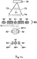
- Fig. 9 shows an illustration of a solution according to the invention, in particular for scanning with a rotating scanner mirror.
- FIG. 9 illustrates an approach according to the invention, how a suitable APD segmentation can be derived, in particular if the uniqueness problem is to be solved.
- the segments S1, S2, S3, S4 and S5 are arranged such that the uniqueness of a received signal for a distance measurement with a measurement frequency at three different rotational speeds of the scanner mirror (corresponding to 25 Hz, 50 Hz and 100 Hz) the fast scan axis can be determined.
- the five segments are formed as circular ring surfaces. If the surfaces of the outer segments are too large with respect to an influence of ambient light, according to the invention, these circular segments can be subdivided further, for example into quadrants.
- the signal dynamics is primarily a problem for the range of short distances.
- the inner segments of the inventive APD are assigned to these distances. This also applies to very fast scanning mirror movements, since they do not produce a significant resulting offset of the point of incidence of the received signal on the detector because of the relatively short light transit time between the target object and the detector.
- a fine subdivision, as shown by Fig. 9 in the middle of the APD circular structure is therefore sufficient to divide the signal at close range to more than one APD segment.
- the light spot is larger at medium distances than the innermost APD segment.
- the radiometric limit distance is shifted to greater distances and the signal dynamics are thereby reduced.
- Fig. 10 shows a block diagram for the signal processing in the signal path of a segmented detector according to the invention or a segmented APD according to the invention, wherein the signal paths for processing the signals of two APD segments S j by means of solid lines and the signal path of a third APD segment S j by means of broken Lines is indicated.
- an additional multiplexer 67 controlled by a "Field Programmable Gate Array” FPGA 64 is also indicated.
- a “Master Clock” 66 clocks the analog-to-digital converter 63, which is designed as, for example a "Multi-Core ADC” or “ADC-Bank", and the FGPA 64.
- the measurement data is finally transferred from the FGPA 64 to a data backup 65.
- the individual reception channels assigned to the APD segments S j can be combined by means of a multiplexer circuit.
- the signal strength can be used as a switching criterion, which received signal, in each case after amplification by a transimpedance amplifier 61 and passage through a filter 62, to an analog-to-digital converter (ADC) 63 is transmitted.
- ADC analog-to-digital converter
- the signal path can also be created or connected as soon as a signal exceeds a predetermined threshold and at the same time this signal is assigned to the shortest distance range.
- the signal path can be connected as soon as a signal exceeds a predetermined threshold and at the same time this signal is assigned to the longest distance range.
- Another possibility of the signal routing is a permanent interconnection of the individual APD segments S j associated receiving channels, each of the channels before the summation point has a different time delay. As a result, a single received pulse is divided into several and time sequentially supplied to an analog-to-digital converter (ADC) 63.
- ADC analog-to-digital converter
- the targets that form the best signal-to-noise ratio (SNR) and therefore provide the most accurate distance results or measurement points are detected and evaluated.
- the first target becomes "first target detection”
- the third case those targets which are farthest from the detector or Receiving segment S j removed but still well measurable, appropriate (“last target detection”).
- the incoming signals are processed in real time, for example with a frequency of 2 MHz. It looks for pulses and determines the amplitudes and times of the signals from the APD segments S j to sub-sampling accuracy. In addition, various statistical quantities such as signal noise and signal-to-noise ratios SNR are calculated.
- the uniqueness can also be determined on the basis of the signal patterns on the different channels. For example, the spot size is correlated with the distance to a target object. The lateral offset of the received light spot on the detector, when the scanning mirror is pivoted at the appropriate speed, is a measure of the distance. Spot size and / or lateral offset of the light spot can be determined by means of a suitable arrangement and shape of the APD segments become.
- the plurality of received signals can also be used to increase the robustness of the data evaluation, namely by means of comparison, correlation or plausibility testing of distances, signal strengths or pulse shapes of the signals assigned to the channels.
- Fig. 11a shows an illustration of an application of a segmented APD 8S according to the invention in LIDAR for a suppression of detection of false signals, in particular due to interference by airborne particles 71, in a coaxial arrangement of transmitter and receiver.
- a segmented APD 8S according to the invention enables a solution to this problem.
- impulses to be assigned to the aerosols meet in each case predominantly the innermost APD segment S1 and less further peripherally arranged APD segments S2, S2 ', S3 and S3'. This makes it possible to identify and hide pulses from short distances, for example from an apparent distance of up to 500 m.
- the circle with the reference symbol SP ⁇ shows a light spot generated by a near target object.
- a coarse distance can be derived by a size estimation of the light spot by means of a signal comparison of the inner three APD segments S1, S2, and S2 '.
- Spots of large distances SP>, SP> 'and SP> are smaller and mainly irradiate only a single APD segment and can therefore be identified.
- Fig. 11b shows one too Fig. 11a
- the optical axis of the receiver is located at the APD segment S3.
- a first APD segment S1 is provided, which is designed so that the correspondingly large received light spots SP ⁇ but also intentional air targets such as backscatter on clouds from a distance of less than 500m distance (81) are measured .
- the other three APD segments S2, S3 and S4 are intended for object targets at medium to greater distances than 500m, while the light spot oscillates synchronously to the mirror movement of the scanner across the three APD segments.
- s (SP) is the track of the received light spot on the receiving segments S2, S3 and S4 characterized as a result of the movement of the scanner mirror, these segments are provided for medium distances (for example, the segments S2 and S3) and for greater distances (for example, the segments S3 and S4).
- the track of the received light spot is above all in the range 82 and at long distances in the range 83.
- the segments which are associated with longer distances are preferably of smaller area than those which receive signals from short distances.
Landscapes
- Physics & Mathematics (AREA)
- Engineering & Computer Science (AREA)
- General Physics & Mathematics (AREA)
- Electromagnetism (AREA)
- Radar, Positioning & Navigation (AREA)
- Remote Sensing (AREA)
- Computer Networks & Wireless Communication (AREA)
- Condensed Matter Physics & Semiconductors (AREA)
- Computer Hardware Design (AREA)
- Microelectronics & Electronic Packaging (AREA)
- Power Engineering (AREA)
- Optical Radar Systems And Details Thereof (AREA)
Claims (15)
- Dispositif de mesure de distance électro-optique, notamment destiné à un dispositif de balayage à laser (1'), à un dispositif de poursuite à laser, à un profileur, à un théodolite, ou à une station totale (1), comportant au moins- une source lumineuse (6) destinée à émettre au moins un signal lumineux en tant que faisceau lumineux d'émission (13), notamment de lumière laser, vers un objet cible (20),- un circuit de réception comportant un détecteur, notamment une diode PIN ou une photodiode à avalanche APD (8S), ayant un composant de réception photosensible destiné à recevoir le signal lumineux rétrodiffusé par l'objet cible en tant que faisceau lumineux de réception (12), et- un composant de commande et d'analyse destiné à déduire une distance par rapport à l'objet cible (20), dans lequel- le composant de réception comporte au moins deux segments de réception (S1, S2, S3, S4, S5, S1i, S2a, S2al, S2ar, Sj) indépendants l'un de l'autre, pour générer indépendamment l'un de l'autre un signal électrique résultant respectif, dans lequel les segments de réception (S1, S2, S3, S4, S5, S1i, S2a, S2al, S2ar, Sj) sont associés à des plages de distances à mesurer prédéfinies ou pouvant être prédéfinies, notamment différentes, caractérisé en ce que- il est prévu au moins deux amplificateurs indépendants, présentant notamment des facteurs d'amplification différents, au sein du circuit de réception destiné aux au moins deux segments de réception (S1, S2, S3, S4, S5, S1i, S2a, S2al, S2ar, Sj).
- Dispositif de mesure de distance selon la revendication 1,
caractérisé en ce que- le faisceau lumineux d'émission (13) est sensiblement collimaté, et présente par conséquent une divergence maximale de 0.5° et plus particulièrement, de 0.01°, et- une optique de collimation à foyer fixe est disposée en amont du détecteur, le détecteur étant notamment positionné dans le plan focal de l'optique de collimation. - Dispositif de mesure de distance selon la revendication 1 ou 2,
caractérisé en ce que les segments de réception sont conçus et agencés de manière à ce que des signaux lumineux rétrodiffusés depuis des plages de distances différentes éclairent des combinaisons définies différentes de segments de réception. - Dispositif de mesure de distance selon l'une quelconque des revendications précédentes,
caractérisé en ce que- il est prévu un amplificateur ayant un facteur d'amplification relativement élevé pour un segment de réception des au moins deux segments de réception qui est associé à une plage de distances supérieure de distances relativement supérieure, et- il est prévu un amplificateur ayant un facteur d'amplification relativement faible pour un segment de réception des au moins deux segments de réception, qui est associé à une plage de distances inférieure de distances relativement proches. - Dispositif de mesure de distance selon l'une quelconque des revendications précédentes,
caractérisé en ce que les segments de réception (S1, S2, S3, S4, S5, S1i, S2a, S2al, S2ar, Sj) indépendants les uns des autres ne se chevauchent pas et sont respectivement espacés les uns des autres, et plus particulièrement, dans lequel les segments de réception (S1, S2, S3, S4, S5, S1i, S2a, S2al, S2ar, Sj) indépendants les uns des autres sont disposés de manière répartie radialement, notamment sous la forme de cercles concentriques. - Dispositif de mesure de distance selon l'une quelconque des revendications précédentes,
caractérisé en ce qu'à chaque segment de réception (S1, S2, S3, S4, S5, S1i, S2a, S2al, S2ar, Sj) est associé, au sein du circuit de réception, un trajet de traitement du signal respectif séparé souhaité, notamment pour des segments de réception différents, et plus particulièrement, dans lequel les signaux électroniques sont respectivement délivrés à un convertisseur analogique-numérique propre. - Dispositif de mesure de distance selon l'une quelconque des revendications précédentes,
caractérisé en ce que des trajets de traitement de signal différents les uns des autres peuvent être attaqués et/ou lus électroniquement de manière séparée, et plus particulièrement, dans lequel des signaux de segments de réception (S1, S2, S3, S4, S5, S1i, S2a, S2al, S2ar, Sj) différents peuvent être lus de manière différentielle les uns des autres à partir de trajets de signaux associés différents. - Dispositif de mesure de distance selon l'une quelconque des revendications précédentes,
caractérisé en ce que le dimensionnement des segments de réception (S1, S2, S3, S4, S5, S1i, S2a, S2al, S2ar, Sj) sont accordés les uns aux autres sur les trajets de signaux associés et sur les signaux lumineux de retour respectifs attendus en provenance de plages de distances différentes, et plus particulièrement, pour une minimisation d'une variation produite entre des signaux forts et faibles en tant que dynamique du signal (50i, 50a) et/ou pour une augmentation d'un rapport signal à bruit pour les trajets de signaux individuels. - Dispositif de mesure de distance selon l'une quelconque des revendications précédentes,
caractérisé en ce qu'au moins un segment de réception est dimensionné et agencé de manière à ce qu'un signal lumineux rétrodiffusé par un objet cible se trouvant dans un domaine proche, notamment < 5 m, puisse être reçu avec une section transversale de faisceau-observée dans un plan de réception - ayant un diamètre relativement élevé et un obscurcissement central relativement élevé, et plus particulièrement, dans lequel le segment de réception est réalisé sous forme circulaire ou sous forme d'arc de cercle et présente un diamètre de cercle extérieur d'au moins 200 µm, et plus particulièrement, d'au moins 500 µm. - Dispositif de mesure de distance selon l'une quelconque des revendications précédentes, dans lequel le dispositif de mesure de distance est prévu pour une mesure de distance devant être considérée comme statique - cela concernant un déplacement de composants d'émission et/ou de réception du dispositif de mesure de distance - et le faisceau lumineux d'émission (13) et le faisceau lumineux de réception (12) s'étendent coaxialement l'un par rapport à l'autre,
caractérisé en ce que- les segments de réception (S1, S2, S3, S4, S5, S1i, S2a, S2al, S2ar, Sj) indépendants les uns des autres sont disposés de manière répartie radialement, et plus particulièrement sous la forme de cercles concentriques, et/ou- des segments de réception (S1, S2, S3, S4, S5, S1i, S2a, S2al, S2ar, Sj) souhaités, notamment périphériques, sont adaptés du point de vue de leur dimensionnement pour la réception de points lumineux de réception de superficie élevée SP(12) afin de déterminer de faibles distances par rapport à un objet cible. - Dispositif de mesure de distance selon l'une quelconque des revendications 1 à 10, dans lequel le dispositif de mesure de distance est prévu pour une mesure de distance devant être considérée comme étant dynamique - cela concernant un déplacement de composants d'émission et/ou de réception du dispositif de mesure de distance - et plus particulièrement, dans lequel le faisceau lumineux d'émission est soumis, lors du fonctionnement, à une rotation rapide autour d'un axe de rotation, et le faisceau lumineux d'émission (13) et le faisceau lumineux de réception (12) s'étendent coaxialement l'un par rapport à l'autre, caractérisé en ce que les segments de réception (S1, S2, S3, S4, S5, S1i, S2a, S2al, S2ar, Sj) indépendants les uns des autres sont disposés de manière répartie axisymétriquement radialement, et plus particulièrement sous la forme de cercles concentriques ou d'arcs de cercle concentriques, dans lequel les segments de réception - en ce qui concerne leur rayon annulaire respectif et à leurs dimensions - sont positionnés et réalisés dépendamment d'un déplacement prévu défini de composants d'émission et/ou de réception du dispositif de mesure de distance.
- Dispositif de mesure de distance selon l'une quelconque des revendications 1 à 10,
caractérisé en ce que le faisceau lumineux d'émission (13) et le faisceau lumineux de réception (12) s'étendent de manière biaxiale l'un par rapport à l'autre avec un décalage (ΔB) et au moins l'un des au moins deux segments de réception (S1, S2, S3, S4, S5, S1i, S2a, S2al, S2ar, Sj) est disposé de manière axialement asymétrique. - Dispositif de mesure de distance selon l'une quelconque des revendications précédentes,
caractérisé en ce que le composant de commande et d'analyse est conçu pour déduire une information de distance grossière sur la base d'une détermination au moyen de laquelle un signal électrique respectif est généré par les segments de réception présents, et d'une lecture de la plage de distances associée à la combinaison déterminée de segments de réception éclairés, et plus particulièrement, dans lequel une distribution d'intensité des signaux est également déterminée pour les segments de réception éclairés et est prise en compte pour la déduction de l'information de distance grossière, et plus particulièrement, dans lequel le composant de commande et d'analyse utilise l'information de distance grossière respective déduite dans le cadre d'une mesure de distance utilisant le temps de propagation des impulsions pour lever une ambiguïté apparaissant lors de l'association d'impulsions d'émission et de réception, et plus particulièrement pour résoudre un problème d'impulsions multiples se propageant. - Procédé de mesure de distance électro-optique consistant au moins à :- émettre un signal lumineux sous la forme d'un faisceau lumineux d'émission (13), notamment de lumière laser, vers un objet cible (20),- recevoir et détecter une partie (42) du signal lumineux émis renvoyée par l'objet cible (20) en tant que faisceau lumineux de réception (12), et- déterminer une distance par rapport à l'objet cible (20), notamment dans le domaine millimétrique ou submillimétrique,dans lequel- la réception et la détection s'effectuent à l'intérieur d'au moins deux segments de réception (S1, S2, S3, S4, S5, S1i, S2a, S2al, S2ar, Sj) indépendants l'un de l'autre, pour générer indépendamment l'un de l'autre un signal électrique résultant respectif, dans lequel les segments de réception (S1, S2, S3, S4, S5, S1i, S2a, S2al, S2ar, Sj) sont associés à des plages de distances à mesurer prédéfinies ou pouvant être prédéfinies, notamment différentes, caractérisé en ce que- les signaux électriques générés indépendamment les uns des autres sont amplifiés indépendamment les uns des autres, notamment avec des facteurs d'amplification différents.
- Procédé de mesure de distance électro-optique selon la revendication 14,
caractérisé en ce que les signaux électrique générés indépendamment les uns des autres par les différents segments de réception (S1, S2, S3, S4, S5, S1i, S2a, S2al, S2ar, Sj) sont également lus de manière différentiable les uns par rapport aux autres à partir de trajets de signaux différents associés respectifs, et plus particulièrement, dans lequel une information de distance grossière est déterminée à partir de la comparaison des signaux générés, notamment en tenant compte d'une taille déterminée d'un point lumineux de réception SP(12),
et plus particulièrement, dans lequel - notamment lors de l'utilisation d'un système LIDAR - l'information de distance grossière déterminée est utilisée pour empêcher une détermination de distance par rapport à des cibles erronées, notamment du fait de la diffusion lumineuse sur des particules d'air, en excluant des distances minimales prédéfinies ou pouvant être prédéfinies et/ou - lors de l'utilisation d'un principe de mesure de temps de propagation d'impulsions-l'information de distance grossière déterminée est utilisée pour lever une ambiguïté pouvant se produire dans l'association d'impulsions d'émission et de réception.
Priority Applications (3)
| Application Number | Priority Date | Filing Date | Title |
|---|---|---|---|
| EP14185404.2A EP2998700B2 (fr) | 2014-09-18 | 2014-09-18 | Dispositif de mesure de distance électro-optique et procédé de mesure de distance |
| US14/857,577 US10006766B2 (en) | 2014-09-18 | 2015-09-17 | Electrooptical distance measuring device and distance measuring method |
| CN201510599659.8A CN105445748B (zh) | 2014-09-18 | 2015-09-18 | 光电测距装置和测距方法 |
Applications Claiming Priority (1)
| Application Number | Priority Date | Filing Date | Title |
|---|---|---|---|
| EP14185404.2A EP2998700B2 (fr) | 2014-09-18 | 2014-09-18 | Dispositif de mesure de distance électro-optique et procédé de mesure de distance |
Publications (3)
| Publication Number | Publication Date |
|---|---|
| EP2998700A1 EP2998700A1 (fr) | 2016-03-23 |
| EP2998700B1 true EP2998700B1 (fr) | 2016-12-07 |
| EP2998700B2 EP2998700B2 (fr) | 2022-12-21 |
Family
ID=51564558
Family Applications (1)
| Application Number | Title | Priority Date | Filing Date |
|---|---|---|---|
| EP14185404.2A Active EP2998700B2 (fr) | 2014-09-18 | 2014-09-18 | Dispositif de mesure de distance électro-optique et procédé de mesure de distance |
Country Status (3)
| Country | Link |
|---|---|
| US (1) | US10006766B2 (fr) |
| EP (1) | EP2998700B2 (fr) |
| CN (1) | CN105445748B (fr) |
Cited By (4)
| Publication number | Priority date | Publication date | Assignee | Title |
|---|---|---|---|---|
| DE102017107666A1 (de) | 2017-04-10 | 2018-10-11 | Sick Ag | Optoelektronischer Sensor und Verfahren zur Erfassung eines Objekts |
| US10175343B2 (en) | 2014-12-04 | 2019-01-08 | Hexagon Technology Center Gmbh | Rangefinder with a laser-like light source |
| WO2020182255A1 (fr) | 2019-03-13 | 2020-09-17 | Jenoptik Optical Systems Gmbh | Dispositif de balayage laser et procédé de mesure tridimensionnelle d'une scène à une distance élevée |
| WO2022028864A1 (fr) | 2020-08-05 | 2022-02-10 | Robert Bosch Gmbh | Procédé de détermination de diaphonie optique d'un capteur lidar, et capteur lidar |
Families Citing this family (24)
| Publication number | Priority date | Publication date | Assignee | Title |
|---|---|---|---|---|
| US9720412B1 (en) | 2012-09-27 | 2017-08-01 | Waymo Llc | Modifying the behavior of an autonomous vehicle using context based parameter switching |
| US10488518B2 (en) * | 2015-06-03 | 2019-11-26 | Ams Sensors Singapore Pte. Ltd. | Optoelectronic module operable for distance measurements |
| WO2017063033A1 (fr) * | 2015-10-12 | 2017-04-20 | Groundprobe Pty Ltd | Lidar à stabilité de pente |
| JP6640541B2 (ja) * | 2015-12-02 | 2020-02-05 | 株式会社トプコン | レーザスキャナ |
| CN116699630A (zh) | 2016-11-10 | 2023-09-05 | 莱卡地球系统公开股份有限公司 | 激光扫描仪 |
| US10942272B2 (en) * | 2016-12-13 | 2021-03-09 | Waymo Llc | Power modulation for a rotary light detection and ranging (LIDAR) device |
| CN106524925A (zh) * | 2016-12-15 | 2017-03-22 | 南京工程学院 | 一种非接触式大型圆形容器截面周长测量装置及方法 |
| CN107241685B (zh) * | 2017-06-07 | 2022-09-16 | 上海禾赛科技有限公司 | 相对运动的设备间的通信装置及方法 |
| EP3425333B1 (fr) * | 2017-07-04 | 2020-10-14 | Hexagon Technology Center GmbH | Instrument d'arpentage pour balayer un objet et acquisition d'images de l'objet |
| DE102017118160A1 (de) * | 2017-08-09 | 2019-02-14 | Valeo Schalter Und Sensoren Gmbh | Ermitteln der maximalen Reichweite eines LIDAR-Sensors |
| EP3450915B1 (fr) * | 2017-08-30 | 2020-11-25 | Hexagon Technology Center GmbH | Tachéomètre électronique ou théodolite pourvus de fonction de balayage et de zones de réception réglables du récepteur |
| DE102017215307A1 (de) * | 2017-09-01 | 2019-03-07 | Robert Bosch Gmbh | Lidar-Anordnung sowie Fahrzeug und Roboter mit einer solchen Lidar-Anordnung |
| JP7117092B2 (ja) * | 2017-09-25 | 2022-08-12 | 株式会社トプコン | レーザ測定方法及びレーザ測定装置 |
| JP7013925B2 (ja) * | 2018-02-23 | 2022-02-01 | 株式会社デンソー | 光学的測距装置およびその方法 |
| US11333765B2 (en) * | 2018-05-17 | 2022-05-17 | Samsung Electronics Co., Ltd. | Distance measuring device and method |
| US10401480B1 (en) * | 2018-12-05 | 2019-09-03 | Luminar Technologies, Inc. | Lidar receiver with multiple detectors for range-ambiguity mitigation |
| WO2020139381A1 (fr) * | 2018-12-26 | 2020-07-02 | Didi Research America, Llc | Système et procédés destinés à des opérations de télémétrie à l'aide de multiples signaux |
| CN109741631A (zh) * | 2019-02-01 | 2019-05-10 | 南京沃旭通讯科技有限公司 | 一种相对位置检测设备及其工作方法 |
| US11402476B2 (en) * | 2019-03-20 | 2022-08-02 | Microvision, Inc. | Method and apparatus for LIDAR channel encoding |
| DE102019107681B4 (de) | 2019-03-26 | 2022-12-01 | Sick Ag | Verfahren zum Betreiben eines abstandsmessenden Überwachungssensors und abstandsmessender Überwachungssensor |
| US11740333B2 (en) | 2019-12-04 | 2023-08-29 | Waymo Llc | Pulse energy plan for light detection and ranging (lidar) devices based on areas of interest and thermal budgets |
| CN113495280B (zh) * | 2020-04-07 | 2024-05-14 | 武汉万集光电技术有限公司 | 激光雷达测距信息的获取方法、装置、电子设备及存储介质 |
| CN112611368B (zh) * | 2020-12-01 | 2022-08-05 | 西南交通大学 | 一种大地精密检测仪自动对齐信标装置 |
| CN112666566A (zh) * | 2021-01-14 | 2021-04-16 | 深圳市杉川机器人有限公司 | 激光雷达测距方法、装置、电子设备及存储介质 |
Citations (10)
| Publication number | Priority date | Publication date | Assignee | Title |
|---|---|---|---|---|
| EP0071667A1 (fr) | 1981-08-11 | 1983-02-16 | Karl-Erik Morander | Dispositif pour déterminer la distance réelle ou virtuelle entre une source lumineuse et un plan à mesurer |
| US5311353A (en) | 1993-03-05 | 1994-05-10 | Analog Modules | Wide dynamic range optical receivers |
| DE10051302A1 (de) | 2000-10-13 | 2002-04-25 | Jenoptik Jena Gmbh | Laserentfernungsmessgerät für große Messbereiche mit speziellem Empfänger |
| EP1329739A2 (fr) | 2002-01-16 | 2003-07-23 | Riegl Lasermeasurement Systems GmbH | Dispositif de prise de vues d'un espace objet |
| DE102006013290A1 (de) | 2006-03-23 | 2007-09-27 | Robert Bosch Gmbh | Vorrichtung zur optischen Distanzmessung sowie Verfahren zum Betrieb einer solchen Vorrichtung |
| EP1879044A1 (fr) | 2006-07-10 | 2008-01-16 | Omron Corporation | Dispositif de radar |
| US20090059183A1 (en) | 2007-09-05 | 2009-03-05 | Casio Computer Co., Ltd. | Distance measuring device and projector including same distance measuring device |
| DE102007053852A1 (de) | 2007-11-12 | 2009-05-14 | Robert Bosch Gmbh | Vorrichtung zur optischen Distanzmessung |
| EP2182377A1 (fr) | 2008-10-30 | 2010-05-05 | Sick Ag | Scanner laser mesurant l'éloignement |
| WO2011029651A1 (fr) | 2009-09-11 | 2011-03-17 | Robert Bosch Gmbh | Télémètre optique |
Family Cites Families (7)
| Publication number | Priority date | Publication date | Assignee | Title |
|---|---|---|---|---|
| US6587072B1 (en) | 2002-03-22 | 2003-07-01 | M/A-Com, Inc. | Pulse radar detection system |
| KR20050014051A (ko) | 2003-07-29 | 2005-02-07 | 안희태 | 초음파 신호에서 주파수 분리를 이용한 거리측정 방법 및장치 |
| US7236235B2 (en) | 2004-07-06 | 2007-06-26 | Dimsdale Engineering, Llc | System and method for determining range in 3D imaging systems |
| EP1686350A1 (fr) | 2005-01-26 | 2006-08-02 | Leica Geosystems AG | Station totale géodésique extensible de façon modulaire |
| CN101398476B (zh) | 2007-09-29 | 2011-07-27 | 广达电脑股份有限公司 | 定位系统 |
| DE102009029372A1 (de) | 2009-09-11 | 2011-03-24 | Robert Bosch Gmbh | Messvorrichtung zur Messung einer Entfernung zwischen der Messvorrichtung und einem Zielobjekt mit Hilfe optischer Messstrahlung |
| US9851202B2 (en) * | 2013-11-27 | 2017-12-26 | Bae Systems Information And Electronic Systems Integration Inc. | Determining a return laser signal associated with a target in laser range finders |
-
2014
- 2014-09-18 EP EP14185404.2A patent/EP2998700B2/fr active Active
-
2015
- 2015-09-17 US US14/857,577 patent/US10006766B2/en active Active
- 2015-09-18 CN CN201510599659.8A patent/CN105445748B/zh active Active
Patent Citations (10)
| Publication number | Priority date | Publication date | Assignee | Title |
|---|---|---|---|---|
| EP0071667A1 (fr) | 1981-08-11 | 1983-02-16 | Karl-Erik Morander | Dispositif pour déterminer la distance réelle ou virtuelle entre une source lumineuse et un plan à mesurer |
| US5311353A (en) | 1993-03-05 | 1994-05-10 | Analog Modules | Wide dynamic range optical receivers |
| DE10051302A1 (de) | 2000-10-13 | 2002-04-25 | Jenoptik Jena Gmbh | Laserentfernungsmessgerät für große Messbereiche mit speziellem Empfänger |
| EP1329739A2 (fr) | 2002-01-16 | 2003-07-23 | Riegl Lasermeasurement Systems GmbH | Dispositif de prise de vues d'un espace objet |
| DE102006013290A1 (de) | 2006-03-23 | 2007-09-27 | Robert Bosch Gmbh | Vorrichtung zur optischen Distanzmessung sowie Verfahren zum Betrieb einer solchen Vorrichtung |
| EP1879044A1 (fr) | 2006-07-10 | 2008-01-16 | Omron Corporation | Dispositif de radar |
| US20090059183A1 (en) | 2007-09-05 | 2009-03-05 | Casio Computer Co., Ltd. | Distance measuring device and projector including same distance measuring device |
| DE102007053852A1 (de) | 2007-11-12 | 2009-05-14 | Robert Bosch Gmbh | Vorrichtung zur optischen Distanzmessung |
| EP2182377A1 (fr) | 2008-10-30 | 2010-05-05 | Sick Ag | Scanner laser mesurant l'éloignement |
| WO2011029651A1 (fr) | 2009-09-11 | 2011-03-17 | Robert Bosch Gmbh | Télémètre optique |
Cited By (6)
| Publication number | Priority date | Publication date | Assignee | Title |
|---|---|---|---|---|
| US10175343B2 (en) | 2014-12-04 | 2019-01-08 | Hexagon Technology Center Gmbh | Rangefinder with a laser-like light source |
| DE102017107666A1 (de) | 2017-04-10 | 2018-10-11 | Sick Ag | Optoelektronischer Sensor und Verfahren zur Erfassung eines Objekts |
| US10948574B2 (en) | 2017-04-10 | 2021-03-16 | Sick Ag | Optoelectronic sensor and method for detecting an object |
| WO2020182255A1 (fr) | 2019-03-13 | 2020-09-17 | Jenoptik Optical Systems Gmbh | Dispositif de balayage laser et procédé de mesure tridimensionnelle d'une scène à une distance élevée |
| WO2022028864A1 (fr) | 2020-08-05 | 2022-02-10 | Robert Bosch Gmbh | Procédé de détermination de diaphonie optique d'un capteur lidar, et capteur lidar |
| DE102020209849A1 (de) | 2020-08-05 | 2022-02-10 | Robert Bosch Gesellschaft mit beschränkter Haftung | Verfahren zum Ermitteln eines optischen Übersprechens eines Lidar-Sensors und Lidar-Sensor |
Also Published As
| Publication number | Publication date |
|---|---|
| US10006766B2 (en) | 2018-06-26 |
| CN105445748B (zh) | 2018-09-07 |
| EP2998700A1 (fr) | 2016-03-23 |
| US20160084651A1 (en) | 2016-03-24 |
| EP2998700B2 (fr) | 2022-12-21 |
| CN105445748A (zh) | 2016-03-30 |
Similar Documents
| Publication | Publication Date | Title |
|---|---|---|
| EP2998700B1 (fr) | Dispositif de mesure de distance électro-optique et procédé de mesure de distance | |
| EP2475957B2 (fr) | Télémètre optique | |
| DE3915627C2 (fr) | ||
| EP3450915B1 (fr) | Tachéomètre électronique ou théodolite pourvus de fonction de balayage et de zones de réception réglables du récepteur | |
| EP2824478B1 (fr) | Capteur optoélectronique et procédé destiné à la détection d'objets et à la détermination de distance dans une zone de surveillance | |
| AT412032B (de) | Verfahren zur aufnahme eines objektraumes | |
| EP3451021A1 (fr) | Appareil de mesure pourvu de fonction de balayage et de zones de réception réglables du récepteur | |
| EP3557284A2 (fr) | Capteur optoélectronique et procédé de détermination de la distance | |
| DE102006013292A1 (de) | Vorrichtung zur optischen Distanzmessung | |
| EP3336576B1 (fr) | Procédé de détection d'une scène tridimensionnelle au moyen d'un système lidar et système lidar correspondant | |
| DE102006013290A1 (de) | Vorrichtung zur optischen Distanzmessung sowie Verfahren zum Betrieb einer solchen Vorrichtung | |
| WO2000026612A1 (fr) | Systeme de mesure de profil et procede approprie | |
| EP2124069A1 (fr) | Système LIDAR omnidirectionnel | |
| EP3330741B1 (fr) | Capteur optoélectronique et procédé de détection d'objets dans une zone de détection | |
| DE4005919C2 (de) | Verfahren und Anordnung zum Ermitteln der Sichtweite für Autofahrer beim Auftreten von Nebel | |
| WO2016116302A1 (fr) | Dispositif et procédé de détection d'objets pour un véhicule automobile | |
| DE2850743C3 (de) | Verfahren und Vorrichtung zur Messung der Abweichung des Sendestrahls von der optischen Achse des Empfangsteleskops bei einem Lidargerät | |
| DE202011052106U1 (de) | Entfernungsmessender optoelektronischer Sensor | |
| WO2015003833A1 (fr) | Détermination d'une distance et d'un angle par rapport à un plan au moyen de plusieurs mesures d'éloignement | |
| EP3736602B1 (fr) | Recherche automatique de marques cibles | |
| DE102018123940B4 (de) | Verfahren und Vorrichtung zur Entfernungsbestimmung | |
| EP0690317A1 (fr) | Méthode et dispositif pour la détermination optique des positions spatiales d'objets réfléchissants | |
| DE3044831A1 (de) | Anordnung zur automatischen beruehrungslosen messung der raeumlichen lage von gegenstaenden | |
| WO2007025398A1 (fr) | Dispositif et procede de demodulation de phase dans un detecteur de distance optique | |
| DE102019106411B4 (de) | Laserscaneinrichtung und Verfahren zur dreidimensionalen Vermessung einer Szenerie in großer Entfernung |
Legal Events
| Date | Code | Title | Description |
|---|---|---|---|
| PUAI | Public reference made under article 153(3) epc to a published international application that has entered the european phase |
Free format text: ORIGINAL CODE: 0009012 |
|
| AK | Designated contracting states |
Kind code of ref document: A1 Designated state(s): AL AT BE BG CH CY CZ DE DK EE ES FI FR GB GR HR HU IE IS IT LI LT LU LV MC MK MT NL NO PL PT RO RS SE SI SK SM TR |
|
| AX | Request for extension of the european patent |
Extension state: BA ME |
|
| 17P | Request for examination filed |
Effective date: 20160330 |
|
| RBV | Designated contracting states (corrected) |
Designated state(s): AL AT BE BG CH CY CZ DE DK EE ES FI FR GB GR HR HU IE IS IT LI LT LU LV MC MK MT NL NO PL PT RO RS SE SI SK SM TR |
|
| RIC1 | Information provided on ipc code assigned before grant |
Ipc: G01C 15/00 20060101AFI20160721BHEP Ipc: G01S 17/08 20060101ALI20160721BHEP Ipc: G01S 7/486 20060101ALI20160721BHEP Ipc: G01S 17/10 20060101ALI20160721BHEP Ipc: H01L 31/10 20060101ALI20160721BHEP Ipc: G01S 17/89 20060101ALI20160721BHEP Ipc: H01L 31/107 20060101ALI20160721BHEP Ipc: G01S 7/481 20060101ALI20160721BHEP Ipc: G01S 7/491 20060101ALI20160721BHEP Ipc: G01C 3/08 20060101ALI20160721BHEP |
|
| GRAP | Despatch of communication of intention to grant a patent |
Free format text: ORIGINAL CODE: EPIDOSNIGR1 |
|
| INTG | Intention to grant announced |
Effective date: 20160830 |
|
| GRAS | Grant fee paid |
Free format text: ORIGINAL CODE: EPIDOSNIGR3 |
|
| GRAA | (expected) grant |
Free format text: ORIGINAL CODE: 0009210 |
|
| STAA | Information on the status of an ep patent application or granted ep patent |
Free format text: STATUS: THE PATENT HAS BEEN GRANTED |
|
| AK | Designated contracting states |
Kind code of ref document: B1 Designated state(s): AL AT BE BG CH CY CZ DE DK EE ES FI FR GB GR HR HU IE IS IT LI LT LU LV MC MK MT NL NO PL PT RO RS SE SI SK SM TR |
|
| REG | Reference to a national code |
Ref country code: GB Ref legal event code: FG4D Free format text: NOT ENGLISH |
|
| REG | Reference to a national code |
Ref country code: CH Ref legal event code: EP Ref country code: AT Ref legal event code: REF Ref document number: 852136 Country of ref document: AT Kind code of ref document: T Effective date: 20161215 |
|
| REG | Reference to a national code |
Ref country code: IE Ref legal event code: FG4D Free format text: LANGUAGE OF EP DOCUMENT: GERMAN |
|
| REG | Reference to a national code |
Ref country code: DE Ref legal event code: R096 Ref document number: 502014002131 Country of ref document: DE |
|
| PG25 | Lapsed in a contracting state [announced via postgrant information from national office to epo] |
Ref country code: LV Free format text: LAPSE BECAUSE OF FAILURE TO SUBMIT A TRANSLATION OF THE DESCRIPTION OR TO PAY THE FEE WITHIN THE PRESCRIBED TIME-LIMIT Effective date: 20161207 |
|
| REG | Reference to a national code |
Ref country code: NL Ref legal event code: FP |
|
| REG | Reference to a national code |
Ref country code: SE Ref legal event code: TRGR |
|
| REG | Reference to a national code |
Ref country code: LT Ref legal event code: MG4D |
|
| PG25 | Lapsed in a contracting state [announced via postgrant information from national office to epo] |
Ref country code: NO Free format text: LAPSE BECAUSE OF FAILURE TO SUBMIT A TRANSLATION OF THE DESCRIPTION OR TO PAY THE FEE WITHIN THE PRESCRIBED TIME-LIMIT Effective date: 20170307 Ref country code: LT Free format text: LAPSE BECAUSE OF FAILURE TO SUBMIT A TRANSLATION OF THE DESCRIPTION OR TO PAY THE FEE WITHIN THE PRESCRIBED TIME-LIMIT Effective date: 20161207 Ref country code: GR Free format text: LAPSE BECAUSE OF FAILURE TO SUBMIT A TRANSLATION OF THE DESCRIPTION OR TO PAY THE FEE WITHIN THE PRESCRIBED TIME-LIMIT Effective date: 20170308 |
|
| PG25 | Lapsed in a contracting state [announced via postgrant information from national office to epo] |
Ref country code: ES Free format text: LAPSE BECAUSE OF FAILURE TO SUBMIT A TRANSLATION OF THE DESCRIPTION OR TO PAY THE FEE WITHIN THE PRESCRIBED TIME-LIMIT Effective date: 20161207 Ref country code: FI Free format text: LAPSE BECAUSE OF FAILURE TO SUBMIT A TRANSLATION OF THE DESCRIPTION OR TO PAY THE FEE WITHIN THE PRESCRIBED TIME-LIMIT Effective date: 20161207 Ref country code: RS Free format text: LAPSE BECAUSE OF FAILURE TO SUBMIT A TRANSLATION OF THE DESCRIPTION OR TO PAY THE FEE WITHIN THE PRESCRIBED TIME-LIMIT Effective date: 20161207 Ref country code: HR Free format text: LAPSE BECAUSE OF FAILURE TO SUBMIT A TRANSLATION OF THE DESCRIPTION OR TO PAY THE FEE WITHIN THE PRESCRIBED TIME-LIMIT Effective date: 20161207 |
|
| REG | Reference to a national code |
Ref country code: DE Ref legal event code: R026 Ref document number: 502014002131 Country of ref document: DE |
|
| PLBI | Opposition filed |
Free format text: ORIGINAL CODE: 0009260 |
|
| PG25 | Lapsed in a contracting state [announced via postgrant information from national office to epo] |
Ref country code: CZ Free format text: LAPSE BECAUSE OF FAILURE TO SUBMIT A TRANSLATION OF THE DESCRIPTION OR TO PAY THE FEE WITHIN THE PRESCRIBED TIME-LIMIT Effective date: 20161207 Ref country code: SK Free format text: LAPSE BECAUSE OF FAILURE TO SUBMIT A TRANSLATION OF THE DESCRIPTION OR TO PAY THE FEE WITHIN THE PRESCRIBED TIME-LIMIT Effective date: 20161207 Ref country code: RO Free format text: LAPSE BECAUSE OF FAILURE TO SUBMIT A TRANSLATION OF THE DESCRIPTION OR TO PAY THE FEE WITHIN THE PRESCRIBED TIME-LIMIT Effective date: 20161207 Ref country code: EE Free format text: LAPSE BECAUSE OF FAILURE TO SUBMIT A TRANSLATION OF THE DESCRIPTION OR TO PAY THE FEE WITHIN THE PRESCRIBED TIME-LIMIT Effective date: 20161207 Ref country code: IS Free format text: LAPSE BECAUSE OF FAILURE TO SUBMIT A TRANSLATION OF THE DESCRIPTION OR TO PAY THE FEE WITHIN THE PRESCRIBED TIME-LIMIT Effective date: 20170407 |
|
| 26 | Opposition filed |
Opponent name: SICK AG Effective date: 20170724 |
|
| PG25 | Lapsed in a contracting state [announced via postgrant information from national office to epo] |
Ref country code: BG Free format text: LAPSE BECAUSE OF FAILURE TO SUBMIT A TRANSLATION OF THE DESCRIPTION OR TO PAY THE FEE WITHIN THE PRESCRIBED TIME-LIMIT Effective date: 20170307 Ref country code: PL Free format text: LAPSE BECAUSE OF FAILURE TO SUBMIT A TRANSLATION OF THE DESCRIPTION OR TO PAY THE FEE WITHIN THE PRESCRIBED TIME-LIMIT Effective date: 20161207 Ref country code: PT Free format text: LAPSE BECAUSE OF FAILURE TO SUBMIT A TRANSLATION OF THE DESCRIPTION OR TO PAY THE FEE WITHIN THE PRESCRIBED TIME-LIMIT Effective date: 20170407 Ref country code: IT Free format text: LAPSE BECAUSE OF FAILURE TO SUBMIT A TRANSLATION OF THE DESCRIPTION OR TO PAY THE FEE WITHIN THE PRESCRIBED TIME-LIMIT Effective date: 20161207 Ref country code: SM Free format text: LAPSE BECAUSE OF FAILURE TO SUBMIT A TRANSLATION OF THE DESCRIPTION OR TO PAY THE FEE WITHIN THE PRESCRIBED TIME-LIMIT Effective date: 20161207 |
|
| REG | Reference to a national code |
Ref country code: FR Ref legal event code: PLFP Year of fee payment: 4 |
|
| PLAX | Notice of opposition and request to file observation + time limit sent |
Free format text: ORIGINAL CODE: EPIDOSNOBS2 |
|
| PG25 | Lapsed in a contracting state [announced via postgrant information from national office to epo] |
Ref country code: DK Free format text: LAPSE BECAUSE OF FAILURE TO SUBMIT A TRANSLATION OF THE DESCRIPTION OR TO PAY THE FEE WITHIN THE PRESCRIBED TIME-LIMIT Effective date: 20161207 Ref country code: SI Free format text: LAPSE BECAUSE OF FAILURE TO SUBMIT A TRANSLATION OF THE DESCRIPTION OR TO PAY THE FEE WITHIN THE PRESCRIBED TIME-LIMIT Effective date: 20161207 |
|
| PLBB | Reply of patent proprietor to notice(s) of opposition received |
Free format text: ORIGINAL CODE: EPIDOSNOBS3 |
|
| PG25 | Lapsed in a contracting state [announced via postgrant information from national office to epo] |
Ref country code: MC Free format text: LAPSE BECAUSE OF FAILURE TO SUBMIT A TRANSLATION OF THE DESCRIPTION OR TO PAY THE FEE WITHIN THE PRESCRIBED TIME-LIMIT Effective date: 20161207 |
|
| REG | Reference to a national code |
Ref country code: IE Ref legal event code: MM4A |
|
| REG | Reference to a national code |
Ref country code: BE Ref legal event code: MM Effective date: 20170930 |
|
| PG25 | Lapsed in a contracting state [announced via postgrant information from national office to epo] |
Ref country code: LU Free format text: LAPSE BECAUSE OF NON-PAYMENT OF DUE FEES Effective date: 20170918 |
|
| PG25 | Lapsed in a contracting state [announced via postgrant information from national office to epo] |
Ref country code: IE Free format text: LAPSE BECAUSE OF NON-PAYMENT OF DUE FEES Effective date: 20170918 |
|
| PG25 | Lapsed in a contracting state [announced via postgrant information from national office to epo] |
Ref country code: BE Free format text: LAPSE BECAUSE OF NON-PAYMENT OF DUE FEES Effective date: 20170930 |
|
| REG | Reference to a national code |
Ref country code: FR Ref legal event code: PLFP Year of fee payment: 5 |
|
| PG25 | Lapsed in a contracting state [announced via postgrant information from national office to epo] |
Ref country code: MT Free format text: LAPSE BECAUSE OF FAILURE TO SUBMIT A TRANSLATION OF THE DESCRIPTION OR TO PAY THE FEE WITHIN THE PRESCRIBED TIME-LIMIT Effective date: 20161207 |
|
| PG25 | Lapsed in a contracting state [announced via postgrant information from national office to epo] |
Ref country code: HU Free format text: LAPSE BECAUSE OF FAILURE TO SUBMIT A TRANSLATION OF THE DESCRIPTION OR TO PAY THE FEE WITHIN THE PRESCRIBED TIME-LIMIT; INVALID AB INITIO Effective date: 20140918 |
|
| APBM | Appeal reference recorded |
Free format text: ORIGINAL CODE: EPIDOSNREFNO |
|
| APBP | Date of receipt of notice of appeal recorded |
Free format text: ORIGINAL CODE: EPIDOSNNOA2O |
|
| APAH | Appeal reference modified |
Free format text: ORIGINAL CODE: EPIDOSCREFNO |
|
| APBQ | Date of receipt of statement of grounds of appeal recorded |
Free format text: ORIGINAL CODE: EPIDOSNNOA3O |
|
| PG25 | Lapsed in a contracting state [announced via postgrant information from national office to epo] |
Ref country code: CY Free format text: LAPSE BECAUSE OF FAILURE TO SUBMIT A TRANSLATION OF THE DESCRIPTION OR TO PAY THE FEE WITHIN THE PRESCRIBED TIME-LIMIT Effective date: 20161207 |
|
| PGFP | Annual fee paid to national office [announced via postgrant information from national office to epo] |
Ref country code: NL Payment date: 20190918 Year of fee payment: 6 Ref country code: SE Payment date: 20190918 Year of fee payment: 6 Ref country code: FR Payment date: 20190927 Year of fee payment: 6 |
|
| PG25 | Lapsed in a contracting state [announced via postgrant information from national office to epo] |
Ref country code: MK Free format text: LAPSE BECAUSE OF FAILURE TO SUBMIT A TRANSLATION OF THE DESCRIPTION OR TO PAY THE FEE WITHIN THE PRESCRIBED TIME-LIMIT Effective date: 20161207 |
|
| PGFP | Annual fee paid to national office [announced via postgrant information from national office to epo] |
Ref country code: CH Payment date: 20190919 Year of fee payment: 6 |
|
| PG25 | Lapsed in a contracting state [announced via postgrant information from national office to epo] |
Ref country code: TR Free format text: LAPSE BECAUSE OF FAILURE TO SUBMIT A TRANSLATION OF THE DESCRIPTION OR TO PAY THE FEE WITHIN THE PRESCRIBED TIME-LIMIT Effective date: 20161207 |
|
| PG25 | Lapsed in a contracting state [announced via postgrant information from national office to epo] |
Ref country code: AL Free format text: LAPSE BECAUSE OF FAILURE TO SUBMIT A TRANSLATION OF THE DESCRIPTION OR TO PAY THE FEE WITHIN THE PRESCRIBED TIME-LIMIT Effective date: 20161207 |
|
| REG | Reference to a national code |
Ref country code: AT Ref legal event code: MM01 Ref document number: 852136 Country of ref document: AT Kind code of ref document: T Effective date: 20190918 |
|
| PG25 | Lapsed in a contracting state [announced via postgrant information from national office to epo] |
Ref country code: AT Free format text: LAPSE BECAUSE OF NON-PAYMENT OF DUE FEES Effective date: 20190918 |
|
| REG | Reference to a national code |
Ref country code: CH Ref legal event code: PL |
|
| REG | Reference to a national code |
Ref country code: NL Ref legal event code: MM Effective date: 20201001 |
|
| PG25 | Lapsed in a contracting state [announced via postgrant information from national office to epo] |
Ref country code: NL Free format text: LAPSE BECAUSE OF NON-PAYMENT OF DUE FEES Effective date: 20201001 |
|
| PG25 | Lapsed in a contracting state [announced via postgrant information from national office to epo] |
Ref country code: FR Free format text: LAPSE BECAUSE OF NON-PAYMENT OF DUE FEES Effective date: 20200930 |
|
| PG25 | Lapsed in a contracting state [announced via postgrant information from national office to epo] |
Ref country code: SE Free format text: LAPSE BECAUSE OF NON-PAYMENT OF DUE FEES Effective date: 20200919 Ref country code: LI Free format text: LAPSE BECAUSE OF NON-PAYMENT OF DUE FEES Effective date: 20200930 Ref country code: CH Free format text: LAPSE BECAUSE OF NON-PAYMENT OF DUE FEES Effective date: 20200930 |
|
| REG | Reference to a national code |
Ref country code: SE Ref legal event code: EUG |
|
| APBU | Appeal procedure closed |
Free format text: ORIGINAL CODE: EPIDOSNNOA9O |
|
| PUAH | Patent maintained in amended form |
Free format text: ORIGINAL CODE: 0009272 |
|
| STAA | Information on the status of an ep patent application or granted ep patent |
Free format text: STATUS: PATENT MAINTAINED AS AMENDED |
|
| 27A | Patent maintained in amended form |
Effective date: 20221221 |
|
| AK | Designated contracting states |
Kind code of ref document: B2 Designated state(s): AL AT BE BG CH CY CZ DE DK EE ES FI FR GB GR HR HU IE IS IT LI LT LU LV MC MK MT NL NO PL PT RO RS SE SI SK SM TR |
|
| REG | Reference to a national code |
Ref country code: DE Ref legal event code: R102 Ref document number: 502014002131 Country of ref document: DE |
|
| PGFP | Annual fee paid to national office [announced via postgrant information from national office to epo] |
Ref country code: GB Payment date: 20230920 Year of fee payment: 10 |
|
| PGFP | Annual fee paid to national office [announced via postgrant information from national office to epo] |
Ref country code: DE Payment date: 20230920 Year of fee payment: 10 |